Trihal cast resin dry type transformers (ENG) - Trinet
Trihal cast resin dry type transformers (ENG) - Trinet
Trihal cast resin dry type transformers (ENG) - Trinet
- No tags were found...

Create successful ePaper yourself
Turn your PDF publications into a flip-book with our unique Google optimized e-Paper software.
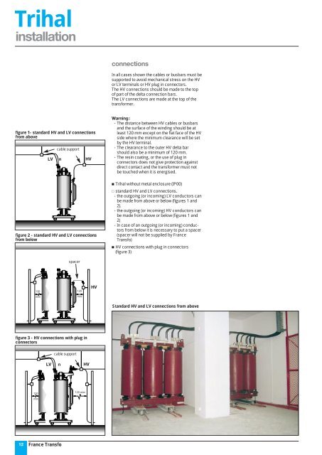
<strong>Trihal</strong>installationconnectionsIn all cases shown the cables or busbars must besupported to avoid mechanical stress on the HVor LV terminals or HV plug in connectors.The HV connections should be made to the topof part of the delta connection bars.The LV connections are made at the top of thetransformer.figure 1- standard HV and LV connectionsfrom abovecable supportLV n HVWarning:- The distance between HV cables or busbarsand the surface of the winding should be atleast 120 mm except on the flat face of the HVside where the minimum clearance will be setby the HV terminal.- The clearance to the outer HV delta barshould also be a minimum of 120 mm.- The <strong>resin</strong> coating, or the use of plug inconnectors does not give protection againstdirect contact and the transformer must notbe touched when it is energised.figure 2 - standard HV and LV connectionsfrom below <strong>Trihal</strong> without metal enclosure (IP00) standard HV and LV connections.- the outgoing (or incoming) LV conductors canbe made from above or below (figures 1 and2).- the outgoing (or incoming) HV conductors canbe made from above or below (figures 1 and2)- In case of an outgoing (or incoming) conductorsfrom below it is necessary to put a spacer(spacer will not be supplied by FranceTransfo) HV connections with plug in connectors(figure 3)spacer120mini120miniHVStandard HV and LV connections from abovefigure 3 - HV connections with plug inconnectorscable supportLV n HV120120 minimini12France Transfo