You also want an ePaper? Increase the reach of your titles
YUMPU automatically turns print PDFs into web optimized ePapers that Google loves.
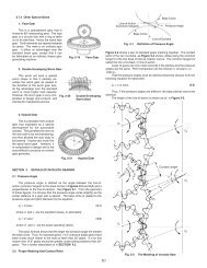
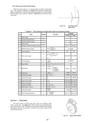
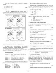
4. Use A <strong>Worm</strong> With A Larger Pressure Angle Than The<strong>Worm</strong> Gear.This is a very complex method, both theoretically andpractically. Usually, the crowning is done to the worm gear, butin this method the modification is on the worm. That is, tochange the pressure angle and pitch of the worm withoutchanging the pitch line parallel to the axis, in accordance withthe relationships shown in Equations 9-4:p x cosα x = p x 'cosα x ' (9-4)In order to raise the pressureangle from before change, α x 'to after change, α x , it isnecessary to increase the axialpitch, P x ' to a new value, P x perEquation (9-4). The amount ofcrowning is represented as thespace between the worm andworm gear at the meshing pointA in Figure 9-9. This amountmay be approximated by thefollowing equation:Amount of Crowning= k Px-Px' d 1 (9-5)Px' 2where:d 1 = Pitch diameter of wormk = Factor from Table 9-5 andFigure 9-10P x = <strong>Axial</strong> pitch after changep x '= <strong>Axial</strong> pitch before changeAn example of calculating worm crowning is shown in Table9-6.Because the theory and equations of these methods are socomplicated, they are beyond the scope of this treatment.Usually, all stock worm gears are produced with crowning.9.4 Self-Locking Of <strong>Worm</strong> MeshSelf-locking is a unique characteristic of worm meshes thatcan be put to advantage. It is the feature that a worm cannot bedriven by the worm gear. It is very useful in the design of someequipment, such as lifting, in that the drive can stop at anyposition without concern that it can slip in reverse. However, insome situations it can be detrimental if the system requiresreverse sensitivity, such as a servo-mechanism.Self-locking does not occur in all worm meshes, since itrequires special conditions as outlined here. In this analysis,only the driving force acting upon the tooth surfaces isconsidered without any regard to losses due to bearing friction,lubricant agitation, etc. The governing conditions are as follows:Let F u1 = tangential driving force of wormThen, F u1 = F n (cosα n sinγ - µ cos γ ) (9-6)where:α n = normal pressure angleγ = lead angle of wormµ = coefficient of frictionF n = normal driving force of wormIf F u1 > 0 then there is no self-locking effect at all. Therefore,F u1 ≤ 0 is the critical limit of self-locking.Let α n in Equation (9-6) be 20º, then the condition:F u1 ≤ 0 will become:(cos20º sinγ - µcosγ ) ≤ 0Figure 9-11 shows the critical limit of self-locking for lead angleγ and coefficient of friction µ. Practically, it is very hard to assessthe exact value of coefficient of friction µ. Further, the bearingloss, lubricant agitation loss, etc. can add many side effects.Therefore, it is not easy to establish precise self-lockingconditions. However, it is true that the smaller the lead angle γ,the more likely the self-locking condition will occur.365