ISOLATED POWER CENTERS - Bender
ISOLATED POWER CENTERS - Bender
ISOLATED POWER CENTERS - Bender
Create successful ePaper yourself
Turn your PDF publications into a flip-book with our unique Google optimized e-Paper software.
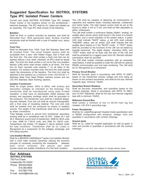
Suggested Specification for ISOTROL SYSTEMSType IPC Isolated Power CentersFurnish and install ISOTROL SYSTEMS Type IPC IsolatedPower Center in the locations shown on the architectural /electrical drawings. The IPC shall be UL Listed and labeled asan assembly. The Type IPC shall consist of the following:BackboxShall be flush or surface mounted as required, and shall befabricated from 14GA galvanized steel. Surface mountedenclosures shall be finished with a coat of hospital ivory, epoxyenamel.Front TrimShall be fabricated from 14GA Type 304 Stainless Steel with#4 brushed finish. The circuit breaker section shall beaccessible from a door, with hidden hinges, that is flush withthe front trim. The door shall contain a flush lock that can beopened without a key when unlocked; all IPCs shall be keyedalike. The front trim shall contain a cut out for the Line IsolationMonitor (LIM) which shall remain visible at all times. The fronttrim for flush mounted units extends 1" on all sides of thebackbox. For surface mounted units, the front trim shall exactlymatch the dimensions of the backbox. The front trim shall beattached to the backbox by a minimum of ten (10) #10-32 x 1"Stainless Steel Oval Head Phillips machine screws and ten(10) #10 Stainless Steel finishing washers.Isolation TransformerShall be single phase, 50Hz or 60Hz, with primary andsecondary voltages as indicated on the drawings. Thetransformer shall be manufactured using class H-ratedinsulation. It shall have an electrostatic shield between theprimary and secondary windings which shall be grounded tothe enclosure. The transformer core shall be a stacked design,securely clamped. Core and coil shall be vacuum impregnated,with a final wrap of insulating material. The core and coilsshall be isolated from the enclosure by means of isolationmounts. The weight of the transformer shall not be supportedby shear connections.Total leakage current to ground from transformer secondarywinding shall be in compliance with UL1047, Tables 30.1 and30.2. Maximum sound level of transformer: 25dB for 5kVA unitsor less, 30dB for 7.5kVA units, and 35db for 10kVA units.Temperature rise limited 115 degees C above ambient underfull load conditions. Transformer shall be UL Listed orRecognized as a component, for the voltages, amperage, andkVA rating required.The LIM shall be capable of detecting all combinations ofcapacitive and resistive faults, including balanced, unbalancedand hybrid faults. The total hazard current shall be set at thefactory to either 2 mA or 5 mA, and shall be field adjustable toeither milliampere.The LIM shall contain a continuous display (digital / analog), anaudible alarm device which shall sound in the event of a hazardcondition, and a visual indication of the system status. A greenLED shall indicate "SAFE" status, a red LED shall indicate"HAZARD" status, and an amber LED shall indicate that theaudible alarm feature is in the "MUTE" mode. A "TEST" buttonshall be provided so the functions of the LIM can be tested byhospital personnel. The digital display, indicating LEDs, and"TEST" button shall all be flush with the face of the LIM andshall be protected by a rugged Lexan front foil. Remote indicatorconnections shall be provided.The LIM shall contain overload protection with an automaticreset feature. It shall be possible to order the LIM with an optionalRS485 communication port and load monitoring. The LIM shallbe UL Recognized as a component.Primary Circuit BreakerShall be two-pole sized in accordance with NFPA 70 (NEC)based on the transformer primary voltage and kVA rating asshown on the contract documents, and shall be full size, thermalmagnetic type, minimum 10kAIC.Secondary Branch BreakersShall be two-pole, ampacities, and quantities based on thecontract drawings. Sized in accordance with NFPA 70 (NEC)and UL1047 Standards. Shall be full size and thermal magnetictype with a minimum 10kAIC.Reference Ground BusShall contain a minimum of one (1) #4-2/0 main lug andnineteen (19) #14-4 grounding lugs.Power ReceptaclesShall be UL Listed/Recognized Hospital Grade specification and/or NEMA configuration with ampacity, voltage, color andquantities in accordance with contract drawings.Ground JacksShall be UL Listed for hospital application as well as green incolor and provide in quantities in accordance with the contractdrawings.Line Isolation MonitorShall be a BENDER LIM2000plus TM series Line Isolation Monitorwith a solid state modular assembly utilizing the dynamicprinciple of constantly monitoring the impedance betweeneach circuit conductor and ground and shallprovide visual and audible indications of a first fault condition.Specifications and other data subject to change without notice.Our AddressISOTROL SYSTEMS700 Fox ChaseCoatesville, PA 19320Phone: 800-833-6834610-383-9655Fax: 610-383-7100E-mail: isotrol@bender.org IPC - 6Medical Division of <strong>Bender</strong> Inc.Rev 3 - 2004' LST


