

ISOLATED POWER CENTERS - Bender
ISOLATED POWER CENTERS - Bender
ISOLATED POWER CENTERS - Bender

Create successful ePaper yourself
Turn your PDF publications into a flip-book with our unique Google optimized e-Paper software.
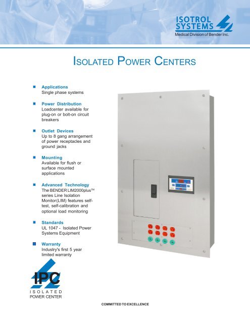
Medical Division of <strong>Bender</strong> Inc.<strong>ISOLATED</strong> <strong>POWER</strong> <strong>CENTERS</strong>ApplicationsSingle phase systemsPower DistributionLoadcenter available forplug-on or bolt-on circuitbreakersOutlet DevicesUp to 8 gang arrangementof power receptacles andground jacksMountingAvailable for flush orsurface mountedapplicationsAdvanced TechnologyThe BENDER LIM2000plus TMseries Line IsolationMonitor(LIM) features selftest,self-calibration andoptional load monitoringStandardsUL 1047 - Isolated PowerSystems EquipmentWarrantyIndustry's first 5 yearlimited warrantyIPC<strong>ISOLATED</strong><strong>POWER</strong> CENTERCOMMITTED TO EXCELLENCE
IntroductionISOTROL SYSTEMS Type IPC Isolated Power Centers havebeen designed to provide isolated power to electrical circuitsinstalled within operating rooms and other electricallysusceptible patient care areas. Designed in strict compliancewith Underwriters Laboratories Standards UL1047, UL1022and UL50, the IPC offers the most current technology for allisolated power distribution requirements.GeneralThe Type IPC typically includes a single phase transformer, aBENDER Line Isolation Monitor (LIM), a reference ground bus,a primary circuit breaker, branch circuit breakers, HospitalGrade power receptacles and Hospital Grade ground jacks.The maximum number of branch circuit breakers is limited tosixteen (16) plug-on or twelve (12) bolt-on.BackboxAll backboxes are fabricated from 14GA galvanized steel.Surface mounted enclosures are finished with a coat ofhospital ivory, epoxy enamel. Outline drawings shown on thefollowing pages of this brochure provide additional dimensionaland construction details.Front TrimManufactured from 14GA Type 304 Stainless Steel with a #4brushed finish, the front trim contains a door with hiddenhinges and a flush mounted key lock that covers the loadcenter. The front trim for flush mounted units extends 1" on allsides of the backbox. For surface mounted units, the front trimshall exactly match the dimensions of the backbox.Isolation TransformerIsolation transformers are available with various primary andsecondary single phase voltages. The transformer ratings aregiven on the isolation transformer data sheet found in ISOTROL'sfull catalog or by request.Line Isolation Monitor (LIM)The BENDER LIM2000plus TM series Line Isolation Monitorprovides a digital / analog display. The LIM is available in singleor three phase models with readout and response values of2 or 5mA. The LIM2000plus TM has a patented measuringprinciple and is capable of detecting all combinations ofcapacitive and resistive faults, including balanced, unbalancedand hybrid faults. A self-test and calibration function is alsofeatured. The LIM2000plus TM series LIM contributes less than35µA to the Total Hazard Current (THC). Available optionsinclude load monitoring and RS485 communication. Forfurther information see the LIM2000plus TM series data sheet.Line Isolation MonitorLIM2000plus TMLoadcenterThe loadcenter is an integral part of the IPC. Included is aprimary circuit breaker which provides protection for theisolation transformer. All Isolated Power Centers canaccommodate either plug-on or bolt-on circuit breakers.Power Receptacles & Ground JacksThe Type IPC provides an eight gang section for HospitalGrade power receptacles and Hospital Grade ground jacks.The Hospital Grade power receptacles are available in eitherstraight-blade (single or duplex) or twist-to-lock style. Eachgang can accommodate one duplex or single power receptacleand one ground jack or two ground jacks.Reference Ground BusThe Type IPC Isolated Power Center is provided with a twenty(20) point reference ground bus to satisfy equipotentialgrounding requirements and for connection to master groundmodules and ground jacks in patient ground modules andreceptacle ground modules. Other ground bus configurationsavailable.Support and ServicesOn-site installation inspection and certification servicesSystem design assistance provided upon requestTechnical support hotline: (800) 833-6834IPC - 2
BENDERTOTALHAZARDCURRENTSAFETESTTRANSFORMERLOADHAZARDmAmA> 80%MUTELIM2000plusOutline Drawing for IPCSingle Phase 3 to10kVAwd1.000"PLANWAd1.000"1411H915563h12%mA167481017201318FRONTA1912VIEW A - ABACKBOXDESIGNATIONTRANSFORMERkVA SIZEhwDIMENSIONdHWB 3, 5, 7.5, 10 41" 24" 8" 43" 26"*CALL FACTORY FOR OTHER CONFIGURATIONS1 Stainless Steel Front Trim 11 Main Circuit Breaker, 2P2 Backbox, Galvanized Steel 12 Branch Circuit Breaker, 2P3 Backplate, Galvanized Steel 13 Loadcenter4 Backplate Mounting Bracket 14 Isolation Transformer, 1Ph5 Transformer Shelf 15 Line Isolation Monitor, 1Ph6 Transformer Shelf Mounting Bracket 16 LIM Connector Plate7 Circuit Breaker Deadfront 17 Ground Bus8 Stainless Steel Door w/Lock 18 Hospital Grade Power Receptacles9 LIM Fuses 19 Hospital Grade Ground Jacks10 LIM Circuit Breaker, 2P (Optional) 20 Receptacle Hat SectionIPC - 3
TOTALHAZARDCURRENTSAFETESTTRANSFORMERLOADmAmA>80%HAZARDMUTEWiring Diagram for IPCSingle Phase 3 to 10kVAT14H2X1INCOMING<strong>POWER</strong>7H1PANELGROUNDX2mA83BENDER%LIM2000plus51357911L1L262468101212OR9L1L212V DC ComMM + * TO REMOTEINDICATORRI1K1/NCK1/COMK1/NOSAFEHAZARDRI2GND2LIM GNDTEST/L3SERIESMK2000(If Required)*METEREDREMOTE ONLYPANELGROUNDTO SYSTEMGROUNDPANELGROUND1011121 LIM Fuses2 LIM Fuses Disconnect3 Loadcenter4 Main Circuit Breaker, 2P5 Branch Circuit Breaker, 2P6 LIM Circuit Breaker, 2P (Optional)7 Isolation Transformer, 1Ph8 Line Isolation Monitor (LIM), 1Ph9 LIM Connector Plate10 Ground Bus11 Hospital Grade Power Receptacles12 Hospital Grade Ground JacksIPC - 4
Selection Guide for Isolated Power Centers (Type IPC)When selecting the Isolated Power Center for your application, use the Product Code below. If you have anyquestions or need further assistance, please call us using our toll-free number: (800) 833-6834.Code A - Basic DesignationIPC: Isolated Power CenterCode B - Transformer Power Rating3: 3kVA 5: 5kVA 7: 7.5kVA 10: 10kVA X: Special kVACode C - Transformer Primary VoltageA: 120V B: 208V C: 240V D: 277VE: 480V G: 220V H: 110V X: Special VoltageCode D - Transformer Secondary VoltageA: 120V B: 208V C: 240V G: 220V H: 110V X: Special VoltageCode E - Phase1: 1 PhaseCode F - Loadcenter Manufacturer and SizeC1: Cutler Hammer 10 Positions Bolt-On only CX: Cutler Hammer12 Positions Plug-On only Lug-to-Lug Circuit Breakers (No Loadcenter)G1: General Electric 14 Positions Plug-On only GX: General ElectricG2: General Electric 16 Positions Plug-On only Lug-to-Lug Circuit Breakers (No Loadcenter)S1: SquareD 12 Positions Plug-On & Bolt-On SX: Square DCode G - Quantity of Branch Circuit BreakersLug-to-Lug Circuit Breakers (No Loadcenter)Code H - Circuit Breaker TypeP: Plug-on B: Bolt-on L: Lug-to-lugCode I - Number of Circuit Breaker Openings in Deadfront (Must be less than or equal to Loadcenter positons)Code J - Quantity of Ground JacksMaximum of 8 Ground JacksCode K - Quantity of Power ReceptaclesMaximum of 8 Power receptaclesCode L - Type of Power ReceptacleThe designation S1, S2, SM, D1, D2, DM, T1, T2 or TMSINGLEDUPLEXTWIST-TO-LOCKTypeS1SMD1DMT1TMVoltage125V125V125VHubbellStyle#ColorHBL8310RRedOTHERHBL8300HRRedOTHERHBL23000HGBlackOTHERNEMA#5-20R5-20Rn/aNote: - Above receptacles are 2P/3W, 20A, single phase- If the IPC contains several types of receptacles, the product code will be expanded by adding multiple blocks ofCodes K and L.- Other receptacles are availableCode M - Backbox Sizes (Height x Width x Depth)B: 41" x 24" x 8" X: SpecialCode N - Type of MountingF: Flush S: SurfaceCall the factory for additional equipment or custom requirementsExample for ISOTROL type IPC Product CodeIPC - 7 B A 1 - C 1 /12 P 12 - 4 - 6 D1- B FCode A Code B Code C Code D Code E Code F Code G Code H Code I Code J Code K Code L Code M Code NIPC - 5
Suggested Specification for ISOTROL SYSTEMSType IPC Isolated Power CentersFurnish and install ISOTROL SYSTEMS Type IPC IsolatedPower Center in the locations shown on the architectural /electrical drawings. The IPC shall be UL Listed and labeled asan assembly. The Type IPC shall consist of the following:BackboxShall be flush or surface mounted as required, and shall befabricated from 14GA galvanized steel. Surface mountedenclosures shall be finished with a coat of hospital ivory, epoxyenamel.Front TrimShall be fabricated from 14GA Type 304 Stainless Steel with#4 brushed finish. The circuit breaker section shall beaccessible from a door, with hidden hinges, that is flush withthe front trim. The door shall contain a flush lock that can beopened without a key when unlocked; all IPCs shall be keyedalike. The front trim shall contain a cut out for the Line IsolationMonitor (LIM) which shall remain visible at all times. The fronttrim for flush mounted units extends 1" on all sides of thebackbox. For surface mounted units, the front trim shall exactlymatch the dimensions of the backbox. The front trim shall beattached to the backbox by a minimum of ten (10) #10-32 x 1"Stainless Steel Oval Head Phillips machine screws and ten(10) #10 Stainless Steel finishing washers.Isolation TransformerShall be single phase, 50Hz or 60Hz, with primary andsecondary voltages as indicated on the drawings. Thetransformer shall be manufactured using class H-ratedinsulation. It shall have an electrostatic shield between theprimary and secondary windings which shall be grounded tothe enclosure. The transformer core shall be a stacked design,securely clamped. Core and coil shall be vacuum impregnated,with a final wrap of insulating material. The core and coilsshall be isolated from the enclosure by means of isolationmounts. The weight of the transformer shall not be supportedby shear connections.Total leakage current to ground from transformer secondarywinding shall be in compliance with UL1047, Tables 30.1 and30.2. Maximum sound level of transformer: 25dB for 5kVA unitsor less, 30dB for 7.5kVA units, and 35db for 10kVA units.Temperature rise limited 115 degees C above ambient underfull load conditions. Transformer shall be UL Listed orRecognized as a component, for the voltages, amperage, andkVA rating required.The LIM shall be capable of detecting all combinations ofcapacitive and resistive faults, including balanced, unbalancedand hybrid faults. The total hazard current shall be set at thefactory to either 2 mA or 5 mA, and shall be field adjustable toeither milliampere.The LIM shall contain a continuous display (digital / analog), anaudible alarm device which shall sound in the event of a hazardcondition, and a visual indication of the system status. A greenLED shall indicate "SAFE" status, a red LED shall indicate"HAZARD" status, and an amber LED shall indicate that theaudible alarm feature is in the "MUTE" mode. A "TEST" buttonshall be provided so the functions of the LIM can be tested byhospital personnel. The digital display, indicating LEDs, and"TEST" button shall all be flush with the face of the LIM andshall be protected by a rugged Lexan front foil. Remote indicatorconnections shall be provided.The LIM shall contain overload protection with an automaticreset feature. It shall be possible to order the LIM with an optionalRS485 communication port and load monitoring. The LIM shallbe UL Recognized as a component.Primary Circuit BreakerShall be two-pole sized in accordance with NFPA 70 (NEC)based on the transformer primary voltage and kVA rating asshown on the contract documents, and shall be full size, thermalmagnetic type, minimum 10kAIC.Secondary Branch BreakersShall be two-pole, ampacities, and quantities based on thecontract drawings. Sized in accordance with NFPA 70 (NEC)and UL1047 Standards. Shall be full size and thermal magnetictype with a minimum 10kAIC.Reference Ground BusShall contain a minimum of one (1) #4-2/0 main lug andnineteen (19) #14-4 grounding lugs.Power ReceptaclesShall be UL Listed/Recognized Hospital Grade specification and/or NEMA configuration with ampacity, voltage, color andquantities in accordance with contract drawings.Ground JacksShall be UL Listed for hospital application as well as green incolor and provide in quantities in accordance with the contractdrawings.Line Isolation MonitorShall be a BENDER LIM2000plus TM series Line Isolation Monitorwith a solid state modular assembly utilizing the dynamicprinciple of constantly monitoring the impedance betweeneach circuit conductor and ground and shallprovide visual and audible indications of a first fault condition.Specifications and other data subject to change without notice.Our AddressISOTROL SYSTEMS700 Fox ChaseCoatesville, PA 19320Phone: 800-833-6834610-383-9655Fax: 610-383-7100E-mail: isotrol@bender.org IPC - 6Medical Division of <strong>Bender</strong> Inc.Rev 3 - 2004' LST


