XR30CX - Dixell
XR30CX - Dixell
XR30CX - Dixell
- No tags were found...

Create successful ePaper yourself
Turn your PDF publications into a flip-book with our unique Google optimized e-Paper software.
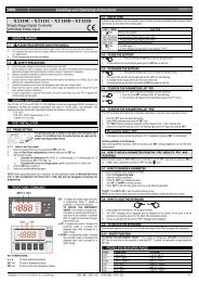
dIXEL Installing and Operating Instructions 159202003015. TECHNICAL DATAHousing: self extinguishing ABS.Case: <strong>XR30CX</strong> frontal 32x74 mm; depth 60mm;Mounting: <strong>XR30CX</strong> panel mounting in a 71x29mm panel cut-outProtection: IP20; Frontal protection: <strong>XR30CX</strong> IP65Connections: Screw terminal block ≤ 2,5 mm 2 wiring.Power supply: according to the model: 12Vac/dc, ±10%; 24Vac/dc, ±10%; 230Vac ±10%,50/60Hz, 110Vac ±10%, 50/60HzPower absorption: 3VA maxDisplay: 3 digits, red LED, 14,2 mm high; Inputs: Up to 4 NTC or PTC probes.Digital input: free voltage contactRelay outputs: compressor SPST 8(3) A, 250Vac; or 20(8)A 250VacAUX: SPDT 8(3) A, 250VacData storing: on the non-volatile memory (EEPROM).Kind of action: 1B; Pollution grade: 2;Software class: A.;Rated impulsive voltage: 2500V; Overvoltage Category: IIOperating temperature: 0÷60 °C;Storage temperature: -30÷85 °C.Relative humidity: 20÷85% (no condensing)Measuring and regulation range: NTC probe: -40÷110°C (-40÷230°F);PTC probe: -50÷150°C (-58÷302°F)Resolution: 0,1 °C or 1°C or 1 °F (selectable); Accuracy (ambient temp. 25°C): ±0,7 °C±1 digit16. CONNECTIONSThe X-REP output excludes the TTL output.. It’s present in the following codes:<strong>XR30CX</strong>- xx2xx, <strong>XR30CX</strong> –xx3xx;16.1 <strong>XR30CX</strong> – 8A COMPRESSORLine8(3)A250V1 2 3 4 5 6 7Light/N.C.Alarm8(3)A250VComp12Vac/dc supply: connect to the terminals 7 and 8.24Vac/dc supply: connect to the terminals 7 and 8.120Vac supply: connect to the terminals 7 and 8.16.2 <strong>XR30CX</strong> – 20A COMPRESSORLine8(3)A250V1 2 3 4 5 6 7Light/N.C.Alarm20(8)A250VComp12Vac/dc supply: connect to the terminals 7 and 8.24Vac/dc supply: connect to the terminals 7 and 8.120Vac supply: connect to the terminals 7 and 8.889 10 11 12RoomHot Key/IV probeTTL or X-REP output9 10 11 12RoomHot Key/IV probeTTL or X-REP outputrES Resolution in=integer; dE= dec.point dE Pr1dLy Display temperature delay 0 ÷ 20.0 min (10 sec.) 0 Pr2IdF Interval between defrost cycles 1 ÷ 120 ore 8 Pr1MdF (Maximum) length for defrost 0 ÷ 255 min 20 Pr1dFd Displaying during defrost rt, it, SEt, DEF it Pr2dAd MAX display delay after defrost 0 ÷ 255 min 30 Pr2ALc Temperat. alarms configurationrE= related to set;Ab = absoluteAb Pr2ALU MAXIMUM temperature alarm Set÷110.0°C; Set÷230°F 110 Pr1ALL Minimum temperature alarm -50.0°C÷Set/ -58°F÷Set -50.0 Pr1AFH Differential for temperat. alarm (0,1°C÷25,5°C) (1°F÷45°F)recovery1 Pr2ALd Temperature alarm delay 0 ÷ 255 min 15 Pr2dAo Delay of temperature alarm at start up 0 ÷ 23h e 50’ 1.3 Pr2AP2 Probe for temperat. alarm ofnP; P1; P2; P3; P4condenserP4 Pr2AL2 Condenser for low temperat. alarm (-55 ÷ 150°C) (-67÷ 302°F) -40 Pr2AU2 Condenser for high temperat. alarm (-55 ÷ 150°C) (-67÷ 302°F) 110 Pr2Differ. for condenser temp. alar. [0,1°C ÷ 25,5°C] [1°F ÷AH2 recovery45°F]5 Pr2Ad2 Condenser temperature alarm delay 0 ÷ 254 (min.) , 255=nU 15 Pr2Delay of cond. temper. alarm at startdA2 up 0.0 ÷ 23h 50’1,3 Pr2Compr. off for condenser lowbLL temperature alarmn(0) - Y(1)n Pr2Compr. off for condenser highAC2 temperature alarmn(0) - Y(1)n Pr2tbA Alarm relay disabling n=no; y=yes y Pr2oA1 2 nd relay configurationALr = alarm; dEF = do notselect it; Lig =Light; AUS=AUX; onF=always on; Fan= Lig Pr2do not select it; db = do notselect it; dF2 = do not select itAoP Alarm relay polarity (oA1=ALr) oP; cL cL Pr2i1P Digital input polarity oP=opening;CL=closing cL Pr1i1F Digital input configurationEAL, bAL, PAL, dor; dEF; Htr,AUSdor Pr1did Digital input alarm delay 0÷255min 15 Pr1nPS Number of activation of pressure0 ÷15switch15 Pr2odc Compress status when open door no; Fan; CPr; F_C no Pr2rrd Regulation restart with door openn – Yalarmy Pr2HES Differential for Energy Saving (-30°C÷30°C) (-54°F÷54°F) 0 Pr2Adr Serial address 0÷247 1 Pr2PbC Kind of probe Ptc; ntc ntc Pr1onF on/off key enabling nu, oFF; ES nu Pr2dP1 Room probe display -- -- Pr2dP3 Third probe display -- -- Pr1dP4 Fourth probe display -- -- Pr1rSE Real set point value actual set -- Pr2rEL Software release -- -- Pr2Ptb Map code -- -- Pr217. DEFAULT SETTING VALUESLabe Name Range °C/°FSet Set point LS÷US 3.0 - - -Hy Differential 0,1÷25.5°C/ 1÷ 255°F 2.0 Pr1LS Minimum set point -50°C÷SET/-58°F÷SET -50.0 Pr2US Maximum set point SET÷110°C/ SET ÷ 230°F 110 Pr2Ot Thermostat probe calibration -12÷12°C /-120÷120°F 0.0 Pr1P3P Third probe presence n=not present; Y=pres. n Pr2O3 Third probe calibration -12÷12°C /-120÷120°F 0 Pr2P4P Fourth probe presence n=not present; Y=pres. n Pr2O4 Fourth probe calibration -12÷12°C /-120÷120°F 0 Pr2OdS Outputs delay at start up 0÷255 min 0 Pr2AC Anti-short cycle delay 0 ÷ 50 min 1 Pr1CCt Continuos cycle duration 0.0÷24.0h 0.0 Pr2CC Set point for continuous cycle (-55.0÷150,0°C) (-67÷302°F)S3 Pr2CO Compressor ON time with faulty probe 0 ÷ 255 minn15 Pr2CO Compressor OFF time with faulty 0 ÷ 255 minF probe30 Pr2CH Kind of action CL=cooling; Ht= heating cL Pr1CF Temperature measurement unit °C ÷ °F °C Pr2<strong>Dixell</strong> S.p.A. Z.I. Via dell’Industria, 2732010 Pieve d’Alpago (BL) ITALYtel. +39 - 0437 - 98 33 - fax +39 - 0437 - 98 93 13E-mail: dixell@dixell.com - http://www.dixell.com1592020030 <strong>XR30CX</strong> GB m&M r1.1 05.03.2007.doc <strong>XR30CX</strong> 4/4