Ag-Tuf Installation Guide - Palram Americas
Ag-Tuf Installation Guide - Palram Americas
Ag-Tuf Installation Guide - Palram Americas
- No tags were found...

Create successful ePaper yourself
Turn your PDF publications into a flip-book with our unique Google optimized e-Paper software.
5. When installing <strong>Ag</strong>-<strong>Tuf</strong> panels vertically on walls or horizontally sloped on ceilings, start installation at the bottom and workup toward the wall eave or ceiling top. Be sure to maintain the correct fastening sequence (Figure: 6a, 6b, 6c, 6d). Commence atbottom edge, at right or left side & proceed to the left (or right) and up. It is possible to start in the middle and work both waystoward the ends. Never fasten both edges first and then work towards the middle; this will result in undue slackand wavy appearance.6. Recommended method and installation steps of <strong>Ag</strong>-<strong>Tuf</strong> on ceilings:a. An installation crew of 5 or 6, two teams (A & B) on mobile scaffoldings, 2 workers on each, with a ground team C toprepare and hand out the lining panel for installation. The panel will be lifted by ropes either at with clamps holdingthe edge, or rolled into a tube.b. A plumb line P will be put up, tomark the precise starting positionPand direction.c. B1 of team B will hold one end of thepanel against the 1ST bottom purlin,while B2 along with team A aligns theA2panel along the plumb-line and holdsit taut, in place.A1d. With the panel aligned and taut, B2will fasten the panel’s edge to thepurlin. Next, with team A stationary,B2 B1holding the liner edge against thelast purlin, the ground crew will pushAteam B’s tower under the subsequentpurlin, the fastening process repeatedand so on.CBe. The liner should always be keptflush and taut during positioningand fastening. A slack panel duringinstallation will result in deformation and wavy appearance.f. It is also possible to begin installation in the middle of a paneland proceed to both sides. Never commence installationfrom both ends towards the middle. It may result in impreciseexecution and undue slack.g. When more than one-length panel is required for ridge toeave, or eave to floor cladding, follow instructions in paragraphD Overlap part 1 and Figures 4a to 4e.h. Horizontal installation on walls should work out virtually thesame (with necessary adjustments).i. Vertical wall cladding can be done with team A1-A2 on a towerand ground crew C1-C2. <strong>Installation</strong> can be begin from the bottomup or vice versa. Working from the top down is more logical andeasier. However, when more than one panel is required, alwaysbegin with the bottom array and proceed upward.7. Use only approved scaffoldings, lifting devices and equipment, for safeand efficient work.8. For safety’s sake, do not leave partly installed panels unattended untilall the required fasteners have been placed and properly tightened.C2Ceiling installationFigure 2A2Wall installationFigure 3A1C12
DOverlap:1. End-Lap: (at panel’s short edges): Minimal recommended overlap - 4" (100 mm). Minimum distance of 2" from each panel edge to thecenterline of the support (line of fasteners). Maximum overlap 8" (200 mm). Always install the lower panels array first, and lap with theupper panels, so the drip down the slope or wall does not penetrate into the ceiling or wall cavity and wet the insulation. (See Fig.4a-4e and paragraph C. 6.i.)2. Side-Lap: One corrugation.3. Panel’s Edge Overhang: The panel’s edge should not extend more than 4” (100 mm) from the centerline of edge support on bothsides. Minimal extension - 2" (50 mm).4. Overlap Seals: In wash areas or extremely wet conditions, <strong>Palram</strong> America recommends installation of butyl-rubber sealing stripalong the whole length of side lap or end lap corrugations.Length OverlapGreca style shown forillustration purposes.Slope DirectionWidth OverlapCeiling installation & fasteners positionsFigure 4a3A25Ceiling array installationsequence 3-4-5Figure 4c4B321BWall array installationsequence 1-2-3Figure 4bDetail AFigure 4dDetail BFigure 4e3
EArching Radius:When lining a curved ceiling, it is possible to set the panels againsta curved (concave) structure so they will arch within their rangeof elasticity, without inducing undue stress. The minimal radiusrecommended for such an arch is 13 ft. (4.00 m)FWall and Ceiling Fastener Location:1. A fastener should be installed every third corrugation valley,screwed into the centerline of each support (Fig 4a, b, c,d). If thepanel is going to be used in conjunction with insulation (blanketsor blown in), in ceilings or walls, a fastener should be used in every2nd corrugation valley.2. A pre-drilled hole, 1/16" larger in diameter than the intendedfastener, is recommended at every fastener location. A specialself-drilling / wood screw, equipped with additional protrusions attop of screw stem, preparing a larger entry hole during insertion,can also be used (Fig 11; Available from others; Not available from<strong>Palram</strong>; Use for <strong>Ag</strong>-<strong>Tuf</strong> PVC panels only; Not recommended for usewith polycarbonate)3. The fasteners should be tightened by an electric screwdriverequipped with adjustable clutch, taking care not to overtighten.4. At the side-lap, two valley fasteners should be installed at bothsides of the overlapping corrugations (Fig 7b).Minimum radius 13 ft.(4.00m)Figure 5Positions of ceiling/wall fasteners in regular installation without insulation.Figure 6a - 38"Figure 6b - 37.8"Positions of ceiling/wall fasteners with insulation mats.Figure 6c - 38"Figure 6d - 37.8"GFasteners, Washers and Gaskets:1. For optimal long-term maintenance-free service, <strong>Palram</strong> <strong>Americas</strong>recommends the use of corrosion resistant #12-14 x 1" fasteningscrew, with <strong>Palram</strong> <strong>Americas</strong> 3/4" (19 mm) special washer withprofiled EPDM rubber gasket, to fasten the panel to the supports.In wash areas, extremely wet areas, or in highly corrosiveenvironments like hog or cattle confinement, stainless steelfasteners are recommended.2. The screw can be hex-head or pan-head Phillips, self-drilling, selftappingor wood screw, according to the type of the supports andthe method of fastener installation. Each fastener will be fittedwith <strong>Palram</strong> <strong>Americas</strong> 3/4" special washer / gasket.3. The screws should be tightened moderately, without deformingthe washer, squashing the gasket and distorting the panel. Carefulattention should be given to assure perpendicular insertion ofthe fasteners.4. Excess tightening and oblique insertion will possibly distort thepanel, induce undue internal stresses, leading to fracture andcracks, eventually ending in failure.5. Never use an impact wrench/driver for fastening <strong>Ag</strong>-<strong>Tuf</strong>.Tighten by hand or by an adjustable torque power screwdriver.Self-tapping screwFigure 7aSelf-drilling screwFigure 7bWood screwFigure 7cINCORRECTExcess overtighteningFigure 8aCORRECTFigure 8bINCORRECTNon-perpendicular.Figure 8cFigure 9aFigure 9b19mm Washer/Gasket helpsprevent over-tightening;provides best seal.Figure 104
HHandling and Storage:1. <strong>Ag</strong>-<strong>Tuf</strong> panels should be transported and stored horizontally on a flat, sturdy pallet whose dimensions are equal to or larger than thepanels themselves. The panels should be secured and fastened to the pallet. It is possible to store panels of smaller dimensions ontop of larger panels of the same type. (Never store long panels on top of smaller ones!)2. In case it is necessary to store the pallet outdoors, cover it with a white opaque polyethylene sheet, cardboard, or other suitablematerials that do not absorb or conduct heat. The total area of the pallet should be covered.3. To minimize the possibility of warp and deformation, <strong>Palram</strong> America recommends installing the panels after they have beenacclimated. The panels should be stored inside the interior space in which they have to be installed until their temperature isequalized to the ambient temperature inside the structure. This way there will be no warp through drastic changes of thermalexpansion/contraction.ICutting:Storage of sheets.Figure 121. It is possible to cut <strong>Ag</strong>-<strong>Tuf</strong> panels with a circular saw, using a blade intended for hardwood or a special one for plastics, rotating at ahigh speed. Advance the saw at a slow feed rate. <strong>Palram</strong> America recommends cutting a few panels stacked together, for cleanercuts and smaller risks of breaks and rough edges.2. It is possible to use an electric jig saw, a handsaw or sheet-metal shears for local or limited cropping, especially for curved lines orcomplex cuts.3. In any case, it is important to support the panels in the vicinity of the cut and clean away the dust and debris generated by cutting.JDrilling:Cutting the sheet.Figure 131. Drilling should be carried out with a drill bit intended for metal. The pre-drilled hole diameter should be 1/16" (2 mm) greater thanthe diameter of the fastening screw. Support the panel in the vicinity of the drilling. Clear away the dust generated by the drillingbefore the insertion of the screws.2. Attention should be paid to drill the required holes perpendicular to the face of the panel.90 oKChemical Resistance:Drilling the sheet.Figure 14(Compatibility to environmental chemicals, sealants and adhesives)1. <strong>Ag</strong>-<strong>Tuf</strong> panels are resistant to a wide variety of chemicals and display limited resistance to others. A third group of chemicals mayattack and damage the panel. The degree of damage will depend on he severity of attack and the duration of exposure.2. In case of doubt consult the list of chemical resistance of PVC to various chemicals, depicted in <strong>Palram</strong> <strong>Americas</strong> publications, to findout if there is any risk to the liner.3. Materials not on the list, which have not received the Manufacturer’s explicit approval, may harm the panel and void all warrantiesand responsibility of the manufacturer for the performance of <strong>Ag</strong>-<strong>Tuf</strong> panels!4. Your local distributor can provide additional information and forward materials for evaluation of their compatibility with <strong>Ag</strong>-<strong>Tuf</strong> panels.5
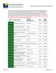
LSealing and Bonding:1. Silicone sealants: <strong>Palram</strong> strongly recommends the useof tested and approved sealing, bonding and adhesivesmaterials that may be required. For a list of sealants thathave been tested and approved, visit:http://www.<strong>Palram</strong><strong>Americas</strong>.com/Sealants/2. Other silicone sealants and sealing, bonding or adhesivesmaterials should be referred to <strong>Palram</strong> America or itsdistributor for evaluation and approval before use.3. Obscure sealing or bonding materials should be referredto <strong>Palram</strong> <strong>Americas</strong> or its distributor for evaluation andapproval before use. Unapproved materials may chemicallyattack the <strong>Ag</strong>-<strong>Tuf</strong>, resulting in failure and voiding any and allwarranties.4. Corrugated closure strips are used to stop entry of water,wind, insects or small animals through the openings aboveor below the edges of the installed sheets. The closurebetween the sheet and edge purlins or top trim is done byan <strong>Ag</strong>-<strong>Tuf</strong> profile contoured closure strips. The strips are heldin place by the sheet fastening screws. They are made ofcross- linked expanded polyethylene (XPE).Shaped foam polyethylene(PE) sealing strip.Figure 15aApproved SealantSilicone sealant.Figure 15b5. In wash areas or extremely wet conditions butyl-rubbersealing strips should be used along the side & end-laps of<strong>Ag</strong>-<strong>Tuf</strong> sheets, to prevent moisture penetrating the wall orceiling cavities.Butyl rubber sealling strip.Figure 15cSlope directionWARNINGDo not use sealing or bonding materials that are not approved specifically by <strong>Palram</strong> America. Expanded polyurethane is notrecommended for use in <strong>Ag</strong>-<strong>Tuf</strong> <strong>Installation</strong>. Extensive use of this material will render the sheets fragile at the area of contact throughmechanical bond effect.When in doubt, consult your <strong>Palram</strong> <strong>Americas</strong> Distributor.6
Inasmuch as <strong>Palram</strong> <strong>Americas</strong> has no control over the use to which others may put the product, it does not guarantee that the same results as thosedescribed herein will be obtained. Each user of the product should make his own tests to determine the product’s suitability for his own particular useincluding the suitability of environmental conditions for the product. Statements concerning possible or suggested uses of the products describedherein are not to be construed as constituting a license under any <strong>Palram</strong> <strong>Americas</strong> patent covering such use or as recommendations for use of suchproducts in the infringement of any patent. <strong>Palram</strong> <strong>Americas</strong> or its distributors cannot be held responsible for any losses incurred through incorrectinstallation of the product. In accordance with our company policy of continual product development you are advised to check with your local<strong>Palram</strong> <strong>Americas</strong> supplier to ensure that you have obtained the most up to date information.<strong>Palram</strong> <strong>Americas</strong> reserves the right to change product specifications and/orinformation contained in this brochure without notice.ISO 9001:2008CCMCEVALUATION13581-RPALRAM AMERICAS9735 Commerce Circle, Kutztown, PA 19530Phone: 610-285-9918 (Toll Free: 800-999-9459)Fax: 610-285-9928E-mail: <strong>Palram</strong><strong>Americas</strong>@palram.comWeb Site: www.<strong>Palram</strong><strong>Americas</strong>.comForm 605 Rev. 11.09.2012 PBW