4" Dredge Instructions - Keene Engineering
4" Dredge Instructions - Keene Engineering
4" Dredge Instructions - Keene Engineering
- No tags were found...

Create successful ePaper yourself
Turn your PDF publications into a flip-book with our unique Google optimized e-Paper software.
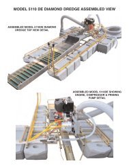
Stage #2Secondary recoveryof coarse goldPrimary classifier screenSecondary classifier screenJet Flareline up carpet with the first riffleAdjustable flow control separatorsheet and carpet should be pulledout as far as possible to start.Stage #3Allows fine material to enter lower section &protects it from high velocity water, providingsuper fine recovery of gold and black sandStage #1Recovers 90% of allvisible gold in theprimary recovery rifflesThree Stage Sluice <strong>Instructions</strong>The 3 stage sluice box requires more water than a normal sluice box to operate correctly. We recommend that theengine be ran at least 2/3rds. throttle or higher. If the engine operates too slow the riffles may become overloaded and aloss of fine gold will occur. The Adjustable flow control separator plate should be pulled out as far as possible toallow maximum flow into the 3rd. stage riffle area. If the Third Stage Riffle appears to be running too clean you canmove the separator plate inward decreasing the water flow allowing more material to accumulate into the riffle section.Side view of 3 stage sluice box2nd stage RiffleSecondary classifierPunch plate1st stage rifflePrimary recovery classifierwoven wireJet flareAluminum separator plate3rd stage riffleStandard Ribbed CarpetWire meshStandard Ribbed CarpetMiners MossBlack Rubber ribbed mattingSluice Box Tilt A d j u s t m e n tMove the sluice Box forward to increase or backward to decrease the angle. The proper sluice box angle adjustment can aff e c tthe recovery of values. If the sluice does not have enough angle the sluice box will "load up" causing the riffle openings to fill withunwanted excess material. Too much angle will cause the material to flow too fast, resulting in loss of values, evidenced by ther i ffles running too clean. If the sluice box is working properly, approximately one third of the riffle should be visible after pumpingclean water for a minute or so. Aloss of values can also occur if the ratio of solid content to water is too heavy. The solid contentshould not exceed 1 part material to two parts water. Anormal sluice box tilt is approximately 3/4” inch to the running foot.Example: Afour foot sluice box should have approximately 3 inches of tilt.First Stage:Cleaning the 3 Stage Sluice BoxA . Position the suction tip away from any material so it is sucking only water. Operate the engine at approximatly 2/3rds. throttlespeed for a several minutes to wash out any excess gravel that has accumulated in the riffle section.B . Turn the engine off or lower the engine speed to a slow idle. Remove primary and secondary classifier screens and riff l e .Remove the carpets and aluminum plate and wash the concentrates into a bucket or tub. Note: the primary riffle or 1st stage canbe cleaned separately without cleaning the entire sluice box. We recommend that the primary riffle be cleaned only once or twicea day. The balance of the sluice should be cleaned every few days, depending on the type of conditions encountered.2nd Stage:A . Unlatch the top 2nd. stage riffle and pivot back towards the jet flare. Roll the carpet up and wash out in a bucket or tub.3rd. Stage.A. Lift the adjustable flow control separator sheet up on it side and rinse the concentrates in to the lower third stage sluice.B. Remove the 3rd stage lower riffle and screen. Splash water on the riffle and screen to rinse any concentrates onto the carpet.Roll up the carpet and wash out the concentrates.Note: many of the above clean up procedures can also be done with the engine idling, however it will require a second person tohold a tub at the end of the sluice.