IJIES-2008 VOLUME 1 ISSUE 1 - inass
IJIES-2008 VOLUME 1 ISSUE 1 - inass
IJIES-2008 VOLUME 1 ISSUE 1 - inass

Create successful ePaper yourself
Turn your PDF publications into a flip-book with our unique Google optimized e-Paper software.
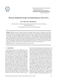
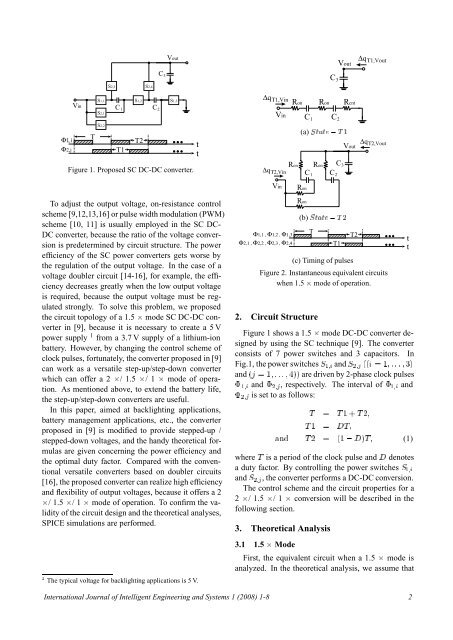
VoutVoutΔq Τ1,VoutS2,3 S2,4C 3C 3Φ1,iΦ2,jVinTS1,1S2,1S2,2S1,2C 1 C 2T1T2S1,3Figure 1. Proposed SC DC-DC converter.ttΔq Τ1,VinRon Ron RcntVinRonΔq Τ2,VinC 1 C 2(a) ËØØ Ì ½VoutRon C 3C 1 C 2Δq Τ2,VoutVinRonTo adjust the output voltage, on-resistance controlscheme [9,12,13,16] or pulse width modulation (PWM)scheme [10, 11] is usually employed in the SC DC-DC converter, because the ratio of the voltage conversionis predetermined by circuit structure. The powerefficiency of the SC power converters gets worse bythe regulation of the output voltage. In the case of avoltage doubler circuit [14-16], for example, the efficiencydecreases greatly when the low output voltageis required, because the output voltage must be regulatedstrongly. To solve this problem, we proposedthe circuit topology of a 1.5 ¢ mode SC DC-DC converterin [9], because it is necessary to create a 5 Vpower supply 1 from a 3.7 V supply of a lithium-ionbattery. However, by changing the control scheme ofclock pulses, fortunately, the converter proposed in [9]can work as a versatile step-up/step-down converterwhich can offer a 2 ¢/ 1.5 ¢/ 1¢ mode of operation.As mentioned above, to extend the battery life,the step-up/step-down converters are useful.In this paper, aimed at backlighting applications,battery management applications, etc., the converterproposed in [9] is modified to provide stepped-up /stepped-down voltages, and the handy theoretical formulasare given concerning the power efficiency andthe optimal duty factor. Compared with the conventionalversatile converters based on doubler circuits[16], the proposed converter can realize high efficiencyand flexibility of output voltages, because it offers a 2¢/ 1.5 ¢/ 1¢ mode of operation. To confirm the validityof the circuit design and the theoretical analyses,SPICE simulations are performed.½ The typical voltage for backlighting applications is 5 V.Φ1,1 , Φ1,2 , Φ1,3Φ2,1 , Φ2,2 , Φ2,3 , Φ2,4Ron(b) ËØØ Ì ¾TT1T2(c) Timing of pulsesFigure 2. Instantaneous equivalent circuitswhen 1.5 ¢ mode of operation.2. Circuit StructureFigure 1 shows a 1.5 ¢ mode DC-DC converter designedby using the SC technique [9]. The converterconsists of 7 power switches and 3 capacitors. InFig.1, the power switches Ë ½ and Ë ¾ ´´ ½¿µand ´ ½µµ are driven by 2-phase clock pulses¨½ and ¨¾ , respectively. The interval of ¨½ and¨¾ is set to as follows:Ì Ì ½·Ì ¾Ì ½ ÌÒ Ì ¾ ´½ µÌ (1)where Ì is a period of the clock pulse and denotesa duty factor. By controlling the power switches Ë ½and Ë ¾ , the converter performs a DC-DC conversion.The control scheme and the circuit properties for a2 ¢/ 1.5 ¢/ 1¢ conversion will be described in thefollowing section.3. Theoretical Analysis3.1 1.5 ¢ ModeFirst, the equivalent circuit when a 1.5 ¢ mode isanalyzed. In the theoretical analysis, we assume thatttInternational Journal of Intelligent Engineering and Systems 1 (<strong>2008</strong>) 1-8 2