IJIES-2008 VOLUME 1 ISSUE 1 - inass
IJIES-2008 VOLUME 1 ISSUE 1 - inass
IJIES-2008 VOLUME 1 ISSUE 1 - inass

You also want an ePaper? Increase the reach of your titles
YUMPU automatically turns print PDFs into web optimized ePapers that Google loves.
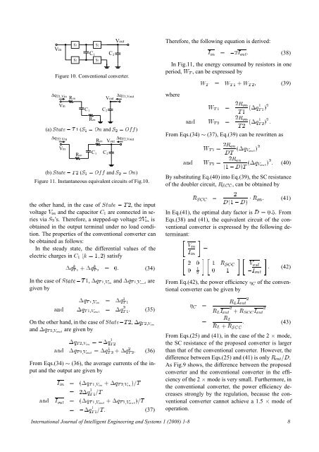
In Eq.(41), the optimal duty factor is ¼. FromEqs.(38) and (41), the equivalent circuit of the conventionalconverter is expressed by the following de-Therefore, the following equation is derived:¡ÕÌ ½ ½ ÌVinS1VoutS2C 1 C 2 (37) S2 S1Figure 10. Conventional converter.Δq Τ1,VinRonVoutΔq Τ1,VoutwhereVinC 1 C 2Ï Ì ½ ¾Ê ÓÒÌ ½ ´¡Õ½ Ì ½ µ¾RonΔq Τ2,VinRonΔq Τ2,VoutVoutVinRonC 1 C 2Ï ¾Ê ÓÒÌ ½ Ì ´¡Õ Î ÓÙص ¾Ê Ë Ì ¾, the inputterminant: ÎÒÁ Ò¡ÕÌ ½ ·¡Õ Ì ¾ ¾ ¼ ½ Ê Ë ¼ (34)½¼ ¼ ½¾ÎÓÙØÁ ÓÙØ¡Õ Ì ½ÎÒ ¡ÕÌ ½ ¾½Ê Ä Á ÓÙØÒ ¡Õ Ì ½ÎÓÙØ ¡ÕÌ ¾ ½ (35) ¾ ¾Ê Ä Á ÓÙØ · ÊË Á ÓÙØ¡Õ Ì ¾ÎÒ ¡ÕÌ ½ ¾Ò ¡Õ Ì ¾ÎÓÙØ ¡ÕÌ ½ ¾ ·¡Õ¾ Ì ¾ (36)Á Ò ´¡Õ Ì ½ÎÒ ·¡Õ Ì ¾ÎÒ µÌ ¾¡ÕÌ ½ ½Ì(a) ËØØ Ì ½ (Ë ½ ÇÒ and Ë ¾ Ç)(b) ËØØ Ì ¾ (Ë ½ Ç and Ë ¾ ÇÒ)Figure 11. Instantaneous equivalent circuits of Fig.10.the other hand, in the case of ËØØvoltage Î Ò and the capacitor ½ are connected in seriesvia Ë ¾ ’s. Therefore, a stepped-up voltage ¾Î Ò isobtained in the output terminal under no load condition.The properties of the conventional converter canbe obtained as follows:In the steady state, the differential values of theelectric charges in ½ ´ ½ ¾µ satisfyIn the case of ËØØ Ì ½, ¡Õ Ì ½ÎÒ and ¡Õ Ì ½ÎÓÙØ aregiven byOn the other hand, in the case of ËØØ Ì ¾, ¡Õ Ì ¾ÎÒand ¡Õ Ì ¾ÎÓÙØ are given byFrom Eqs.(34) (36), the average currents of the inputand the output are given byÒ Á ÓÙØ ´¡Õ Ì ½ÎÓÙØ ·¡Õ Ì ¾ÎÓÙØ µÌÁ Ò ¾Á ÓÙØ (38)In Fig.11, the energy consumed by resistors in oneperiod, Ï Ì , can be expressed byÏ Ì Ï Ì ½ · Ï Ì ¾ (39)Ò Ï ¾Ê ÓÒÌ ¾ Ì ¾ ´¡Õ½ Ì ¾ µ¾ From Eqs.(34) (37), Eq.(39) can be rewritten asÒ Ï Ì ¾ ¾Ê ÓÒ´½ µÌ ´¡Õ Î ÓÙص ¾ (40)By substituting Eq.(40) into Eq.(39), the SC resistanceof the doubler circuit, Ê Ë , can be obtained by¾´½ µ ¡ Ê ÓÒ (41) (42)From Eq.(42), the power efficiency of the conventionalconverter can be given byÊ ÄÊ Ä · Ê Ë (43)From Eqs.(25) and (41), in the case of the 2 ¢ mode,the SC resistance of the proposed converter is largerthan that of the conventional converter. However, thedifference between Eqs.(25) and (41) is only Ê ÒØ .As Fig.9 shows, the difference between the proposedconverter and the conventional converter in the efficiencyof the 2 ¢ mode is very small. Furthermore, inthe conventional converter, the power efficiency decreasesstrongly by the regulation, because the conventionalconverter cannot achieve a 1.5 ¢ mode ofoperation.International Journal of Intelligent Engineering and Systems 1 (<strong>2008</strong>) 1-8 8