IJIES-2008 VOLUME 1 ISSUE 1 - inass
IJIES-2008 VOLUME 1 ISSUE 1 - inass
IJIES-2008 VOLUME 1 ISSUE 1 - inass

You also want an ePaper? Increase the reach of your titles
YUMPU automatically turns print PDFs into web optimized ePapers that Google loves.
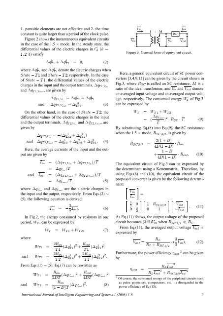
1. parasitic elements are not effective and 2. the timeconstant is quite larger than a period of the clock pulse.Figure 2 shows the instantaneous equivalent circuitsin the case of the 1.5 ¢ mode. In the steady state, thedifferential values of the electric charges in ´ ½ ¾ ¿µ satisfyI inVin1 : MI outRSCVo VoutFigure 3. General form of equivalent circuit.¡Õ Ì ½ ·¡Õ Ì ¾ ¼ (2)where ¡ÕÌ ½ and ¡Õ Ì ¾denote the electric charges whenËØØ Ì ½ and ËØØ Ì ¾, respectively. In the caseof ËØØ Ì ½, the differential values of the electriccharges in the input and the output terminals, ¡Õ Ì ½ÎÒand ¡Õ Ì ½ÎÓÙØ , are given by¡Õ Ì ½ÎÒ ¡ÕÌ ½ ½ ¡Õ¾ Ì ½Ò ¡Õ Ì ½ÎÓÙØ ¡Õ Ì ¿ ½ (3)Here, a general equivalent circuit of SC power converters[3,4,9,12] can be given by the circuit shown inFig.3, where Ê Ë is called an SC resistance, Å is aratio of the ideal transformer, and Î Ò and Î ÓÙØ denotean averaged input voltage and an averaged output voltage,respectively. The consumed energy Ï Ì of Fig.3can be expressed byOn the other hand, in the case of ËØØ Ì ¾, thedifferential values of the electric charges in the inputand the output terminals, ¡Õ Ì ¾ÎÒ and ¡Õ Ì ¾ÎÓÙØ , aregiven by¡Õ Ì ¾ÎÒ ´¡ÕÌ ½ ¾ ·¡Õ¾ Ì ¾ µÒ ¡Õ Ì ¾ÎÓÙØ ¡ÕÌ ½ ¾ ·¡Õ¾ Ì ¾ ·¡Õ¿ Ì ¾ (4)Here, the average currents of the input and the outputare given byÁ Ò ´¡Õ Ì ½ÎÒ ·¡Õ Ì ¾ÎÒ µÌ ¡Õ ÎÒ ÌÒ Á ÓÙØ ´¡Õ Ì ½ÎÓÙØ ·¡Õ Ì ¾ÎÓÙØ µÌ ¡Õ ÎÓÙØ Ì (5)where ¡Õ ÎÒ and ¡Õ ÎÓÙØ are the electric charges inthe input and the output, respectively. From Eqs.(2) (5), the following equation is derived:¿Á Ò Á ÓÙØ (6)¾In Fig.2, the energy consumed by resistors in oneperiod, Ï Ì , can be expressed bywhereÏ Ì Ï Ì ½ · Ï Ì ¾ (7)Ï Ì ½ ¾Ê ÓÒÌ ½ ´¡Õ½ Ì ½ µ¾ · ÊÒØÌ ½ ´¡Õ½ Ì ½ µ¾Ò Ï ¾Ê ÓÒ¾ÊÌ ¾ Ì ¾ ´¡Õ½ Ì ¾ µ¾ ÓÒ ·Ì ¾ ´¡Õ¾ Ì ¾ µ¾ From Eqs.(1) (5), Eq.(7) can be rewritten asÏ Ê ÓÒÌ ½ ¾Ì ´¡Õ Î ÓÙص ¾ · ÊÒØÌ ´¡Õ Î ÓÙص ¾Ê ÓÒÒ Ï Ì ¾ ´½ µÌ ´¡Õ Î ÓÙص ¾ (8)Ï Ì Ï Ì ½ · Ï Ì ¾¡Õ Î ÓÙØ ´ µ ¾ ¡ Ê Ë ¡ Ì (9)ÌBy substituting Eq.(8) into Eq.(9), the SC resistancewhen the 1.5 ¢ mode, Ê Ë¿¾ ,isgivenbyÊ Ë¿¾ ¾´½ · µ´½ µ ¡ Ê ÓÒ· ½ ´½ µ ¡ Ê ÒØ (10)The equivalent circuit of Fig.3 can be expressed bythe determinant using a Kettenmatrix. Therefore, byusing Eqs.(6) and (10), the equivalent circuit of theproposed converter is given by the following determinant: ÎÒ¾¿Á Ò¼¼¿¾½¼Ê Ë¿¾½ÎÓÙØÁ ÓÙØ (11)As Eq.(11) shows, the output voltage of the proposedcircuit becomes ´¿¾µÎ Ò when Ê Ë¿¾ Ê Ä .From Eq.(11), the averaged output voltage Î ÓÙØ isexpressed byÊ ÄÎ ÓÙØ ¡ ´ ¿Ê Ä · Ê Î Òµ (12)Ë¿¾ ¾Furthermore, the power efficiency ¿¾ 2 can be givenby¾Ê Ä Á ÓÙØ ¿¾ ¾ ¾Ê Ä Á ÓÙØ · ÊË¿¾ Á ÓÙØ ¾ Of course, the consumed energy of the peripheral circuits suchas pulse generators, comparators, etc. is disregarded in thepower efficiency of Eq.(13).International Journal of Intelligent Engineering and Systems 1 (<strong>2008</strong>) 1-8 3