Servo solenoid valves with on-board electronics ... - Bosch Rexroth
Servo solenoid valves with on-board electronics ... - Bosch Rexroth
Servo solenoid valves with on-board electronics ... - Bosch Rexroth

Create successful ePaper yourself
Turn your PDF publications into a flip-book with our unique Google optimized e-Paper software.
Electric Drives<br />
and C<strong>on</strong>trols Hydraulics<br />
Linear Moti<strong>on</strong> and<br />
Assembly Technologies Pneumatics Service<br />
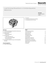
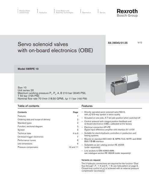
<str<strong>on</strong>g>Servo</str<strong>on</strong>g> <str<strong>on</strong>g>solenoid</str<strong>on</strong>g> <str<strong>on</strong>g>valves</str<strong>on</strong>g><br />
<str<strong>on</strong>g>with</str<strong>on</strong>g> <strong>on</strong>-<strong>board</strong> electr<strong>on</strong>ics (OBE)<br />
Model 5WRPE 10<br />
Size 10<br />
Unit series 2X<br />
Maximum working pressure P 1 , P 2 , A, B 210 bar (3045 PSI),<br />
T 50 bar (725 PSI)<br />
Nominal flow rate 70 l/min (18.50 GPM), Δp 11 bar (160 PSI)<br />
Table of c<strong>on</strong>tents<br />
C<strong>on</strong>tents Page<br />
Features 1<br />
Ordering data and scope of delivery 2<br />
Standard types 2<br />
Functi<strong>on</strong>, secti<strong>on</strong>al diagram 3<br />
Symbol 3<br />
Technical data 4 to 6<br />
On-<strong>board</strong> trigger electr<strong>on</strong>ics 7<br />
Performance curves 8<br />
Unit dimensi<strong>on</strong>s 9<br />
Pressure compensator 10 and 11<br />
Features<br />
RA 29045/01.05<br />
1/12<br />
– Directly operated servo <str<strong>on</strong>g>solenoid</str<strong>on</strong>g> valve NG10,<br />
<str<strong>on</strong>g>with</str<strong>on</strong>g> pQ 5/3-way symbol in servo quality<br />
– Actuated <strong>on</strong> <strong>on</strong>e side, A-T fail-safe positi<strong>on</strong> when switched off<br />
– C<strong>on</strong>trol <str<strong>on</strong>g>solenoid</str<strong>on</strong>g> <str<strong>on</strong>g>with</str<strong>on</strong>g> integral positi<strong>on</strong> feedback and<br />
<strong>on</strong>-<strong>board</strong> electr<strong>on</strong>ics (OBE), calibrated at the factory<br />
– Electrical c<strong>on</strong>necti<strong>on</strong> 6P+PE<br />
Signal input difference amplifier <str<strong>on</strong>g>with</str<strong>on</strong>g> interface A1 ±10V<br />
– Suitable for electrohydraulic c<strong>on</strong>trollers in producti<strong>on</strong> and<br />
testing systems<br />
– Mounts <strong>on</strong> standard ISO 4401-5, NFPA T3.5.1M R1 and ANSI<br />
B93.7 D 05 interface<br />
– Subplates as per catalog secti<strong>on</strong> RE 45055<br />
(order separately)<br />
– Line sockets to DIN 43563-AM6,<br />
see catalogue secti<strong>on</strong> RE 08008 (order separately)<br />
Variants <strong>on</strong> request<br />
The 5 hydraulic c<strong>on</strong>necti<strong>on</strong>s are required for the functi<strong>on</strong> “Dual<br />
flow-through”, P g A and P g B, see hole pattern <strong>on</strong> page 8.<br />
1 2<br />
Closed-loop c<strong>on</strong>trol of pQ is achieved <str<strong>on</strong>g>with</str<strong>on</strong>g> an external pressure<br />
compensator (accessory).
2/12 <strong>Bosch</strong> <strong>Rexroth</strong> Corp. | Industrial Hydraulics 5WRPE10 | RA 29045/01.05<br />
Ordering data and scope of delivery<br />
With <strong>on</strong>-<strong>board</strong><br />
trigger electr<strong>on</strong>ics = E<br />
Without sleeve no designati<strong>on</strong><br />
Size 10 = 10<br />
Symbols<br />
5/3 way versi<strong>on</strong><br />
A B<br />
A B<br />
P1P2 T<br />
Side of inductive positi<strong>on</strong> transducer<br />
A B<br />
a 0 b<br />
P1 P2 T<br />
Standard types<br />
5WRP E 10 F B 70 L – 2X / G24 K0/A1 M *<br />
a 0 b<br />
P1 P2 T<br />
= F<br />
(Standard) = B<br />
Type 5WRPE 10 F Material No.<br />
5WRPE 10 FB70L –2X/G24K0 / A1M 0 811 402 107<br />
Accessory, pressure compensator<br />
Further informati<strong>on</strong><br />
in plain text<br />
M = NBR seals,<br />
suitable for mineral oils<br />
(HL, HLP) to DIN 51524<br />
Interface for<br />
trigger electr<strong>on</strong>ics<br />
A1 = Setpoint input ±10 V<br />
Electrical c<strong>on</strong>necti<strong>on</strong><br />
K0 = <str<strong>on</strong>g>with</str<strong>on</strong>g>out line socket <str<strong>on</strong>g>with</str<strong>on</strong>g> plug<br />
to DIN 43563-AM6<br />
Order line socket separately<br />
Voltage supply of trigger electr<strong>on</strong>ics<br />
G24 = +24 V DC<br />
2X = Unit series 20 to 29<br />
(installati<strong>on</strong> and c<strong>on</strong>necti<strong>on</strong> dimensi<strong>on</strong>s unchanged)<br />
Flow characteristic<br />
L = Linear<br />
Nominal flow rate at 11 bar valve pressure difference<br />
(11 bar/metering notch)<br />
Size 10<br />
70 = 70 l/min (18.49 GPM)<br />
See pressure compensator <strong>on</strong> pages 11 and 12 kg (lbs) Material No.<br />
6 (13.2) 0 811 401 219
5WRPE10 | RA 29045/01.05 Industrial Hydraulics | <strong>Bosch</strong> <strong>Rexroth</strong> Corp. 3/12<br />
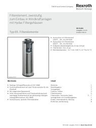
Functi<strong>on</strong>, secti<strong>on</strong>al diagram<br />
<str<strong>on</strong>g>Servo</str<strong>on</strong>g> <str<strong>on</strong>g>solenoid</str<strong>on</strong>g> valve 5WRPE 10<br />
Symbol<br />
A B<br />
P1P2 T<br />
EN 61000-6-2<br />
EN 61000-6-3<br />
Valve body C<strong>on</strong>trol <str<strong>on</strong>g>solenoid</str<strong>on</strong>g> <str<strong>on</strong>g>with</str<strong>on</strong>g> positi<strong>on</strong> transducer<br />
Accessories, not included in scope of delivery<br />
(4 x) M6 x 40 DIN 912–10.9 Fastening screws 2 910 151 209<br />
* Line sockets 6P+PE, KS 1 834 482 022<br />
see also RE 08008<br />
KS 1 834 482 026<br />
MS 1 834 482 023<br />
MS 1 834 482 024<br />
KS 90° 1 834 484 252<br />
Testing and service equipment<br />
– Test box type VT-PE-TB3, see RE 30065<br />
– Test adapter 6P+PE type VT-PA-2, see RE 30068
4/12 <strong>Bosch</strong> <strong>Rexroth</strong> Corp. | Industrial Hydraulics 5WRPE10 | RA 29045/01.05<br />
Technical data<br />
General<br />
C<strong>on</strong>structi<strong>on</strong> Spool type valve, operated directly<br />
Actuati<strong>on</strong> Proporti<strong>on</strong>al <str<strong>on</strong>g>solenoid</str<strong>on</strong>g> <str<strong>on</strong>g>with</str<strong>on</strong>g> positi<strong>on</strong> c<strong>on</strong>trol, OBE<br />
Type of mounting Subplate, mounting hole c<strong>on</strong>figurati<strong>on</strong> NG10 (ISO 4401-05-04-0-94)<br />
Installati<strong>on</strong> positi<strong>on</strong> Opti<strong>on</strong>al<br />
Ambient temperature range °C (°F) –20…+50 (–4...122)<br />
Weight kg (lbs) 7.1 (15.65)<br />
Vibrati<strong>on</strong> resistance, test c<strong>on</strong>diti<strong>on</strong> Max. 25 g, shaken in 3 dimensi<strong>on</strong>s (24 h)<br />
Hydraulic [measured <str<strong>on</strong>g>with</str<strong>on</strong>g> HLP 46, � oil = 40°C ± 5°C (104°F ± 41°F )]<br />
Pressure fluid Hydraulic oil to DIN 51524…535, other fluids after prior c<strong>on</strong>sultati<strong>on</strong><br />
Viscosity range recommended mm2 /s (SUS) 20…100 (93...464)<br />
max. permitted mm2 /s (SUS) 10…800 (46...3708)<br />
Pressure fluid temperature range °C (°F) –20…+70 (–4...+154)<br />
Maximum permissible degree of Class 18/16/13 1)<br />
c<strong>on</strong>taminati<strong>on</strong> of pressure fluid<br />
Purity class to ISO 4406 (c)<br />
Flow directi<strong>on</strong> See symbol<br />
Nominal flow at l/min (GPM) P g A 1 70 (18.49)<br />
Δp = 11 bar per notch 2) P g A + P g B 1 2 70 + 70 (18.49 + 18.49)<br />
A g T 65 (17.17)<br />
Max. working pressure bar (PSI) Port P , P , A, B: 210 (3045)<br />
1 2<br />
Max. pressure bar (PSI) Port T: 50 (725)<br />
Operating limits at Δp bar (PSI) See diagram<br />
Leakage at 100 bar cm3 /min
5WRPE10 | RA 29045/01.05 Industrial Hydraulics | <strong>Bosch</strong> <strong>Rexroth</strong> Corp. 5/12<br />
Technical data<br />
Electrical, trigger electr<strong>on</strong>ics integrated in the valve<br />
Cyclic durati<strong>on</strong> factor % 100<br />
Degree of protecti<strong>on</strong> IP 65 to DIN 40050 and IEC 14434/5<br />
C<strong>on</strong>necti<strong>on</strong> Line socket 6P+PE, DIN 43563<br />
Power supply<br />
Terminal A:<br />
24 V DCnom min. 21 V DC/max. 40 V DC<br />
Terminal B: 0 V Ripple max. 2 V DC<br />
Power c<strong>on</strong>sumpti<strong>on</strong> Solenoid 60 mm = 60 VA max.<br />
External fuse 2.5 AF Input, “Standard” versi<strong>on</strong><br />
Terminal D: UE Terminal E:<br />
Difference amplifier, R = 100 kΩ<br />
i<br />
0 ... ±10 V<br />
0 V<br />
Max. differential input voltage<br />
at 0 V<br />
D g B<br />
E g B } max. 18 V DC<br />
Test signal, “Standard” versi<strong>on</strong> LVDT<br />
Terminal F: UTest 0...±10 V<br />
Terminal C: Reference 0 V<br />
Protective c<strong>on</strong>ductor and screen See pin assignment (installati<strong>on</strong> c<strong>on</strong>forms to CE)<br />
Recommended cable See pin assignment<br />
up to 20 m (62.62 ft) 7 x 0.75 mm2 (0.27 x 0.03 in2 )<br />
up to 40 m (131.23 ft) 7 x 1 mm2 (0.27 x 0.04 in2 )<br />
Calibrati<strong>on</strong> Calibrated at the factory, see valve performance curve<br />
Supply 24V =<br />
Signal: 0…+/–10V<br />
LVDT Signal: 0…+/–10V<br />
A–T<br />
P 1–A<br />
P 1–A+P 2–B<br />
P 2–B<br />
–10V … 0 … +10V<br />
LVDT Signal:<br />
+/–10V<br />
stroke<br />
II sign.
6/12 <strong>Bosch</strong> <strong>Rexroth</strong> Corp. | Industrial Hydraulics 5WRPE10 | RA 29045/01.05<br />
C<strong>on</strong>necti<strong>on</strong><br />
For electrical data, see page 5 and<br />
Operating Instructi<strong>on</strong>s 1 819 929 083<br />
C<strong>on</strong>trol<br />
Customer<br />
Technical notes <strong>on</strong> the cable<br />
Versi<strong>on</strong>: – Multi-wire cable<br />
– Extra-finely stranded wire to VDE 0295, Class 6<br />
– Protective c<strong>on</strong>ductor, green/yellow<br />
– Cu braided screen<br />
Types: – e.g. Ölflex-FD 855 CP<br />
(from Lappkabel company)<br />
No. of wires: – Determined by type of valve,<br />
plug types and signal assignment<br />
Cable Ø: – 0.75 mm 2 (0.03 in 3 )up to 20 m (65.61 ft)length<br />
– 1.0 mm 2 (0.04 in 3 ) up to 40 m (131.23 ft) length<br />
Outside Ø: – 9.4...11.8 mm (0.3...0.46 in)– Pg11<br />
– 12.7...13.5 mm (0.50...0.53 in) – Pg16<br />
Note<br />
C<strong>on</strong>nector<br />
Amplifier<br />
Voltage supply 24 V DC nom,<br />
if voltage drops below 18 V DC, rapid shutdown resembling<br />
“Enable OFF” takes place internally.<br />
Electrical signals emitted via the trigger electr<strong>on</strong>ics (e.g. actual<br />
values) must not be used to shut down safety-relevant machine<br />
functi<strong>on</strong>s! (See European Standard, “Technical Safety<br />
Requirements for Fluid-Powered Systems and Comp<strong>on</strong>ents –<br />
Hydraulics”, EN 982.)
5WRPE10 | RA 29045/01.05 Industrial Hydraulics | <strong>Bosch</strong> <strong>Rexroth</strong> Corp. 7/12<br />
On-<strong>board</strong> trigger electr<strong>on</strong>ics<br />
Block diagram/pin assignment<br />
Versi<strong>on</strong> A1: U D–E ±10 V<br />
Pin assignment 6P+PE<br />
Versi<strong>on</strong> A1: U D–E ±10 V<br />
(R i = 100 kΩ)<br />
Power supply<br />
Supply zero<br />
Ref. zero *<br />
Setpoint 0...±10 V<br />
Actual positi<strong>on</strong><br />
0...±10 V<br />
Protective<br />
c<strong>on</strong>ductor<br />
Screen<br />
* Do not c<strong>on</strong>nect to supply zero!<br />
Valve
8/12 <strong>Bosch</strong> <strong>Rexroth</strong> Corp. | Industrial Hydraulics 5WRPE10 | RA 29045/01.05<br />
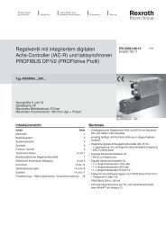
Performance curves – measured <str<strong>on</strong>g>with</str<strong>on</strong>g> HLP 46, ϑ oil = 40 °C ±5 °C (104 °F ±41 °F)<br />
Flow rate/Signal functi<strong>on</strong> Operating limits<br />
Q l/min (GPM)<br />
140 (37.0)<br />
120 (31.7)<br />
100 (26.4)<br />
80 (20.1)<br />
60 (15.8)<br />
40 (10.6)<br />
20 (5.3)<br />
0<br />
Pressure gain<br />
Bode diagram<br />
* calibrated ±1 %<br />
** calibrated ±5 %<br />
140 (37.0)<br />
120 (31.7)<br />
100 (26.4)<br />
80 (20.1)<br />
60 (15.8)<br />
40 (10.6)<br />
20 (5.3)<br />
0<br />
Q l/min (GPM)<br />
Δp bar (PSI)<br />
220 (3190)<br />
200 (2900)<br />
150 (2175)<br />
100 (1450)<br />
50 (725)<br />
40<br />
(10.6)<br />
80<br />
(20.1)<br />
120<br />
(31.7)<br />
Q l/min (GPM)<br />
160<br />
(42.3)<br />
200<br />
(52.8)
5WRPE10 | RA 29045/01.05 Industrial Hydraulics | <strong>Bosch</strong> <strong>Rexroth</strong> Corp. 9/12<br />
Unit dimensi<strong>on</strong>s – nominal dimensi<strong>on</strong>s in mm (inches)<br />
81 (3.19)<br />
39 (1.54)<br />
Pg 11<br />
30 (1.18)<br />
15 not included in scope of delivery<br />
(0.60)<br />
11<br />
Ø 6.6<br />
(0.259)<br />
24<br />
114 (4.49)<br />
(0.43) (0.94)<br />
102 (4.02) 129 (5.08)<br />
Mounting hole c<strong>on</strong>figurati<strong>on</strong>: NG10 (ISO 4401-05-04-0-94)<br />
For subplates, see catalogue secti<strong>on</strong> RE 45055<br />
Required surface quality<br />
of mating comp<strong>on</strong>ent<br />
1) Deviates from standard<br />
2) Thread depth:<br />
Ferrous metal 1.5 x Ø*<br />
N<strong>on</strong>-ferrous 2 x Ø ** 5/3 – NG10<br />
* (NG10 min. 10.5 mm) ** R = P 2<br />
X<br />
Y<br />
(1/4-20 UNC x 1-1/2”)<br />
P A T B F1 F2 F3 F4 R<br />
27 (1.06) 16.7 (0.66) 3.2 (0.13) 37.3 (1.47) 0 54 (2.13) 54 (2.13) 0 50.8 (2.0)<br />
6.3 (0.25) 21.4 (0.84) 32.5 (1.28) 21.4 (0.84) 0 0 46 (1.81) 46 (1.81) 32.5 (1.28)<br />
� 10.5 1) 10.5 1) 10.5 1) 10.5 1) M6 2) M6 2) M6 2) M6 2) 10.5 1)<br />
129 (5.08)
10/12 <strong>Bosch</strong> <strong>Rexroth</strong> Corp. | Industrial Hydraulics 5WRPE10 | RA 29045/01.05<br />
Pressure compensator<br />
Size 10<br />
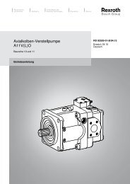
Applicati<strong>on</strong><br />
A combinati<strong>on</strong> of flow rate c<strong>on</strong>trol and pressure compensati<strong>on</strong>.<br />
The flow rate Q is determined by the throttle cross-secti<strong>on</strong>s<br />
P 1 , R, A and P 2 , R, B. Either a single or a double flow may be<br />
selected. In many applicati<strong>on</strong>s, the valve is combined <str<strong>on</strong>g>with</str<strong>on</strong>g> a<br />
variable-displacement pump. The pressure/flow compensator<br />
keeps the pressure drops through the valve at a c<strong>on</strong>stant level<br />
(see Fig. 1 <strong>on</strong> page 11).<br />
The same functi<strong>on</strong> is achieved in c<strong>on</strong>stant-displacement<br />
pumps, too, by means of a pressure compensator. Here, Q max. is<br />
determined by the c<strong>on</strong>trol springs of the pressure compensator<br />
(see Fig. 2 <strong>on</strong> page 11).<br />
Symbol p max. Δp Q nom<br />
The pressure p is measured by an external pressure sensor and<br />
transmitted to an electr<strong>on</strong>ic pressure compensator as an actual<br />
value. Just as the build-up of pressure in the c<strong>on</strong>sumer takes<br />
place and approaches the setpoint value, the valve functi<strong>on</strong> is<br />
determined by the pressure compensator. Even in situati<strong>on</strong>s<br />
where the pressure is decreasing, the valve can regulate the oil<br />
as necessary via the A-T metering notch.<br />
Pressure compensati<strong>on</strong> can be achieved both by means of<br />
electr<strong>on</strong>ics provided by the customer and using a <strong>Rexroth</strong><br />
pressure compensator.<br />
Note<br />
You will find more detailed informati<strong>on</strong> in the RE data sheets:<br />
– Pressure sensors RE 30271<br />
– p/Q regulator RE 30134.<br />
bar (PSI) bar (PSI) l/min (GPM) kg (lbs)<br />
p/Q-NG10 210 8 120 6.0 0 811 401 219<br />
(3045) (116) (31.7) (13.2)<br />
M6 x 115 DIN 912–10.9 –<br />
M6 x 120 DIN 912–10.9 2 910 151 227
5WRPE10 | RA 29045/01.05 Industrial Hydraulics | <strong>Bosch</strong> <strong>Rexroth</strong> Corp. 11/12<br />
Applicati<strong>on</strong><br />
Figure 1: <str<strong>on</strong>g>with</str<strong>on</strong>g> variable-displacement pump Figure 2: <str<strong>on</strong>g>with</str<strong>on</strong>g> pressure compensator 0 811 401 219<br />
Unit dimensi<strong>on</strong>s – nominal dimensi<strong>on</strong>s in mm (inches)<br />
75<br />
(2.95)<br />
41<br />
(1.61)<br />
70<br />
(2.75)<br />
40<br />
(1.57)<br />
46 (1.81)<br />
39.7 (1.56)<br />
24.5 (0.96)<br />
12 (0.47)<br />
13.5<br />
(0.53)<br />
Ø 6.6<br />
(0.26)<br />
50.8 (2.00)<br />
37.3 (1.47)<br />
27 (1.06)<br />
16.7 (0.66)<br />
3.2<br />
(0.13)<br />
54<br />
(2.12)<br />
116<br />
(4.56)<br />
38<br />
(1.49)<br />
176<br />
(6.92)<br />
47<br />
(1.85)<br />
Required surface quality<br />
of mating comp<strong>on</strong>ent<br />
69<br />
(2.71)<br />
74<br />
(2.91)
12/12 <strong>Bosch</strong> <strong>Rexroth</strong> Corp. | Industrial Hydraulics 5WRPE10 | RA 29045/01.05<br />
Notes<br />
<strong>Bosch</strong> <strong>Rexroth</strong> Corp.<br />
Industrial Hydraulics<br />
2315 City Line Road<br />
Bethlehem, PA 18017-2131<br />
USA<br />
Teleph<strong>on</strong>e (610) 694-8300<br />
Facsimile (610) 694-8467<br />
www.boschrexroth-us.com<br />
© This document, as well as the data, specifi cati<strong>on</strong>s and other<br />
informati<strong>on</strong> set forth in it, are the exclusive property of <strong>Bosch</strong> <strong>Rexroth</strong><br />
Corporati<strong>on</strong>. Without their c<strong>on</strong>sent it may not be reproduced or given to<br />
third parties.<br />
The data specifi ed above <strong>on</strong>ly serve to describe the product. No<br />
statements c<strong>on</strong>cerning a certain c<strong>on</strong>diti<strong>on</strong> or suitability for a certain<br />
applicati<strong>on</strong> can be derived from our informati<strong>on</strong>. The informati<strong>on</strong> given<br />
does not release the user from the obligati<strong>on</strong> of own judgment and<br />
verifi cati<strong>on</strong>. It must be remembered that our products are subject to a<br />
natural process of wear and aging.