INSTALLATION INSTRUCTIONS Fan Coils FEM4P ... - PROFLO
INSTALLATION INSTRUCTIONS Fan Coils FEM4P ... - PROFLO
INSTALLATION INSTRUCTIONS Fan Coils FEM4P ... - PROFLO

You also want an ePaper? Increase the reach of your titles
YUMPU automatically turns print PDFs into web optimized ePapers that Google loves.
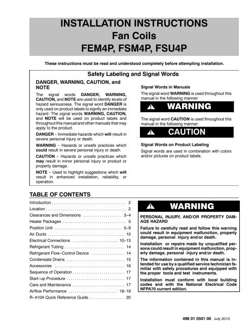
<strong>INSTALLATION</strong> <strong>INSTRUCTIONS</strong><strong>Fan</strong> <strong>Coils</strong><strong>FEM4P</strong>, FSM4P, FSU4PThese instructions must be read and understood completely before attempting installation.DANGER, WARNING, CAUTION, andNOTEThe signal words DANGER, WARNING,CAUTION, and NOTE are used to identify levels ofhazard seriousness. The signal word DANGER isonly used on product labels to signify an immediatehazard. The signal words WARNING, CAUTION,and NOTE will be used on product labels andthroughout this manual and other manuals that mayapply to the product.DANGER -- Immediate hazards which will result insevere personal injury or death.WARNING -- Hazards or unsafe practices whichcould result in severe personal injury or death.CAUTION -- Hazards or unsafe practices whichmay result in minor personal injury or product orproperty damage.NOTE -- Used to highlight suggestions which willresult in enhanced installation, reliability, oroperation.Safety Labeling and Signal WordsSignal Words in ManualsThe signal word WARNING is used throughout thismanual in the following manner:WARNING!WARNINGThe signal word CAUTION is used throughout thismanual in the following manner:!CAUTIONSignal Words on Product LabelingSignal words are used in combination with colorsand/or pictures on product labels.TABLE OF CONTENTSIntroduction .................................... 2Location ....................................... 2Clearances and Dimensions ................... 3--4Heater Packages ............................... 5Position Unit ................................. 5--9Air Ducts ..................................... 10Electrical Connections ...................... 10--13Refrigerant Tubing ............................. 14Refrigerant Flow--Control Device ................ 14Condensate Drains ............................ 15Accessories .................................. 16Sequence of Operation ......................... 17Start--up Procedure ............................ 17Care and Maintenance ......................... 17Airflow Performance ........................ 18--19R--410A Quick Reference Guide ................. 20! WARNINGPERSONAL INJURY, AND/OR PROPERTY DAM-AGE HAZARDFailure to carefully read and follow this warningcould result in equipment malfunction, propertydamage, personal injury and/or death.Installation or repairs made by unqualified personscould result in equipment malfunction, propertydamage, personal injury and/or death.The information contained in this manual is intendedfor use by a qualified service technician familiarwith safety procedures and equipped withthe proper tools and test instruments.Installation must conform with local buildingcodes and with the National Electrical CodeNFPA70 current edition.496 01 5501 00 July 2010
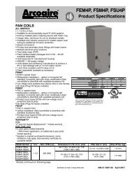
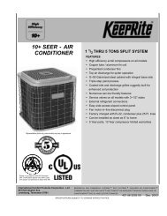
<strong>INSTALLATION</strong> <strong>INSTRUCTIONS</strong><strong>Fan</strong> <strong>Coils</strong>: <strong>FEM4P</strong>, FSM4P, FSU4PINTRODUCTIONModels <strong>FEM4P</strong>, FSM4P, and FSU4P are for R--410Arefrigerant.Models <strong>FEM4P</strong> and FSM4P are designed for maximumflexibility and can be used for upflow, horizontal left orright, and downflow applications (accessory kit requiredfor downflow).Model FSU4P is designed for upflow installation, and canbe field modified for downflow applications (accessory kitrequired).LOCATIONSelect the best position which suits the installation siteconditions. The location should provide adequatestructural support, space in the front of the unit for serviceaccess, clearance for return air and supply ductconnections, space for refrigerant piping connections andcondensate drain line connections. If heaters are beinginstalled make sure adequate clearance is maintainedfrom supply duct work. See Clearances in Figure 1 andFigure 2.If the unit is located in an area of high humidity, nuisancesweating of casing may occur. On these installations a wrapof 2” (51mm) fiberglass insulation with a vapor barrier isrecommended.<strong>FEM4P</strong> models are available for system sizes 1--1/2 -- 4tons (18,000 -- 48,000 BTUH) nominal cooling capacity.<strong>FEM4P</strong> uses a refrigerant piston metering device with anECM integral electronically commutated motor forefficiency.FSM4P and FSU4P models are available for systemsizes 1--1/2 -- 4 tons (18,000 -- 48,000 BTUH) nominalcooling capacity. FSM4P and FSU4P use a refrigerantpiston metering device with 2--speed PSC (permanentsplit capacitor) motors.All models require a field supplied air filter. Factoryapproved electric heater packages are available in sizes5kW through 30kW. See Product Specification literaturefor available accessory kitsNOTE: Internal filter can be accessed from separate filterdoor. If the filter can NOT be easily accessed, a remotefilter is recommended. Refer to ACCA Manual D forremote filter sizing.! WARNINGFIRE HAZARDFailure to maintain proper clearances could result inpersonal injury, death, and/or property damage.When heaters are installed, maintain clearances fromcombustible materials as specified on unit ratingplate. Do not use plastic lined or combustible flexibleducting within 36 inches of the supply end of the fancoil.2 496 01 5501 00
<strong>INSTALLATION</strong> <strong>INSTRUCTIONS</strong><strong>Fan</strong> <strong>Coils</strong>: <strong>FEM4P</strong>, FSM4P, FSU4PFigure 2Clearances and Unit Dimensions - FSM4P, FSU4P( OPENING)BCFEAGHD(SERVICE ACCESS)( OPENING)38 - 11 - 82NoHeatersWithHeatersREQUIRED CLEARANCES -- ALL MODELS inches (mm)All Sides 0From Supply Duct 0All Sides 0From First 3 feet of Supply Duct to Combustibles 1 (25)From Supply Duct to Combustibles after 3 feet 0FSM4P, FSU4P inches (English)Unit Size A B C D E F G H1800 47--5/8 17--5/8 15--3/4 15--5/8 22--1/16 11 21 19--13/162400 49--5/8 17--5/8 15--3/4 15--5/8 22--1/16 11 21 19--13/163000 53--7/16 21--1/8 19--1/4 19--1/8 22--1/16 11 21 19--13/163600 53--7/16 21--1/8 19--1/4 19--1/8 22--1/16 11 21 19--13/164200 49--5/8 21--1/8 19--1/4 19--1/8 22--1/16 11 21 19--13/164800 53--7/16 24--11/16 22--3/4 22--11/16 22--1/16 11 24 19--13/16FSM4P, FSU4P mm (SI Metric)Unit Size A B C D E F G H1800 1210 448 400 397 560 279 533 5032400 1261 448 400 397 560 279 533 5033000 1357 537 489 486 560 279 533 5033600 1357 537 489 486 560 279 533 5034200 1261 537 489 486 560 279 533 5034800 1357 627 578 576 560 279 610 5034 496 01 5501 00
<strong>INSTALLATION</strong> <strong>INSTRUCTIONS</strong>HEATER PACKAGESFactory approved, field installed, UL listed heaterpackages are available from the equipment supplier. Seeunit rating plate for a list of factory approved heaters.POSITION UNITUnit can stand or lie on floor, or hang from ceiling or wall.Allow space for wiring, piping, and servicing unit.! CAUTIONPROPERTY DAMAGE HAZARDFailure to follow this caution may result in propertydamageA field fabricated auxiliary drain pan, with a separatedrain is REQUIRED for all installations over afinished living space or in any area that may bedamaged by overflow from a restricted main drainpan. In some localities, local codes require an auxiliarydrain pan for ANY horizontal installation.<strong>Fan</strong> <strong>Coils</strong>: <strong>FEM4P</strong>, FSM4P, FSU4PHeaters that are not factory approved could causedamage which would not be covered under theequipment warranty.A. UPFLOW <strong>INSTALLATION</strong>If return air is to be ducted through a floor, set unit on floorover opening and use 1/8 to 1/4 inch thick (3 to 6 mmthick) fireproof resilient gasket between duct, unit, andfloor.Side return is a field option on slope coil models. Cutopening per dimensions shown in Figure 3. Afield--supplied bottom closure is required.Figure 3Upflow InstallationPOWER ENTRYOPTIONSFRONT SERVICE CLEARANCE18 - 48 models = 21” (533 mm)60 model = 24” (610 mm)A-COILUNITSUPFLOW/DOWNFLOWSECONDARY DRAIN1½”FIELD SUPPLIEDSUPPLY DUCTLOW VOLTENTRYOPTIONSSLOPE COIL UNITSMODEL SIZEA18 12" (305mm)2417" (432mm)30 19" (483mm)UPFLOW/DOWNFLOWPRIMARY DRAIN19” (483mm)2½”(64mm)AFIELD MODIFIEDSIDE RETURNLOCATION FORSLOPE COILUNITS ONLYUPFLOW/DOWNFLOWSECONDARY DRAINUPFLOW/DOWNFLOWPRIMARY DRAINFIELD SUPPLIEDRETURN PLENUM496 01 5501 00 5
<strong>INSTALLATION</strong> <strong>INSTRUCTIONS</strong>B. DOWNFLOW <strong>INSTALLATION</strong>! CAUTIONPRODUCT OR PROPERTY DAMAGE HAZARDFailure to follow this caution may result in productor property damageThe conversion of the fan coil to downflow requiresspecial procedures for the condensatedrains on both A -coil and Slope -coil units. Thevertical drains have an overflow hole between theprimary and secondary drain holes. This hole isplugged for all applications except downflow, andmust be used for downflow.Failure to follow instructions could result in personalinjury or product and property damage.In this application, field conversion of the evaporator coilis required using accessory Downflow Kit along with anaccessory Base Kit. Set unit on floor over opening anduse 1/8” to 1/4” thick fireproof resilient gasket betweenduct, unit, and floor. Refer to installation instructionspackaged with accessory kit. See Product Specificationliterature for kit part numbers.During the conversion process, removed the plastic capcovering the vertical drains only and discard.<strong>Fan</strong> <strong>Coils</strong>: <strong>FEM4P</strong>, FSM4P, FSU4PRemove the plug from the overflow hole and discard.At completion of the downflow installation, caulk aroundthe vertical pan fitting to door joint to retain low air leakperformance of the unit.NOTE: Gasket kit number (EBAC01GSK) is alsorequired for all downflow applications to maintain low airleak/low sweat performance.C. HORIZONTAL <strong>INSTALLATION</strong>Unit must NOT be installed with access panels facing upor down. Access panels must only face to the side.<strong>FEM4P</strong> and FSM4P models are factory built forhorizontal left installation (refer to Figure 4 and Figure 5).They can be field converted to horizontal right (accessoryGasket Kit required, see Product Specification literaturefor part number). Refer to Figure 6 and Figure 7.NOTE: When suspending unit from ceiling, dimples incasing indicate suitable location of screws for mountingmetal support straps (refer to Figure 4).NOTE: For optimum condensate drainage performancein horizontal installations, unit should be leveled along itslength and width.Figure 4Slope Coil In Horizontal Left Application (<strong>FEM4P</strong> & FSM4P factory configuration)A-COILHORIZONTAL LEFTFIELDSUPPLIEDHANGINGSTRAPSSECONDARYDRAINPRIMARYDRAINSECONDARYDRAINFRONT SERVICE CLEARANCE(FULL FACE OF UNIT)18 - 48 models = 21” (533mm)60 model = 24” (610mm)LOW VOLTENTRYOPTIONS1¾” (45mm)FILTER ACCESSCLEARANCEPOWERENTRYOPTIONSPRIMARYDRAIN6 496 01 5501 00
<strong>INSTALLATION</strong> <strong>INSTRUCTIONS</strong><strong>Fan</strong> <strong>Coils</strong>: <strong>FEM4P</strong>, FSM4P, FSU4PFigure 5A -Coil in Horizontal Left Application (<strong>FEM4P</strong> & FSM4P factory configuration)AFACTORY SHIPPEDHORIZONTAL LEFTAPPLICATIONBCCOILBRACKETCOILSUPPORTRAILDRAIN PANSUPPORTBRACKETCOILBRACKETHORIZONTALDRAIN PANAIR SEALASSEMBLYREFRIGERANTCONNECTIONSPRIMARY DRAINHORIZONTAL LEFTSECONDARY DRAINHORIZONTAL LEFTHorizontal Right Conversion of Units With Slope<strong>Coils</strong>1. Remove blower and coil access panel and fittingpanel (refer to Figure 6).2. Remove coil mounting screw securing coilassembly to right side casing flange.3. Remove coil assembly.4. Lay fan coil unit on its right side and reinstall coilassembly with condensate pan down (refer to Figure 6).5. Attach coil to casing flange using coil mountingscrew previously removed.6. Align holes with tubing connections andcondensate pan connections, and reinstall accesspanels and fitting panel. After brazing, make sureliquid and suction tube grommets are in place toprevent air leaks and cabinet sweating.Figure 6Conversion for Horizontal Right Applications - Slope CoilCOIL MOUNTINGSCREWBLOWERASSEMBLYCOIL SUPPORT RAILSLOPE COILDRAINPANREFRIGERANTCONNECTIONSPRIMARY DRAINSECONDARY DRAIN496 01 5501 00 7
<strong>INSTALLATION</strong> <strong>INSTRUCTIONS</strong>Horizontal Right Conversion of Units With A -<strong>Coils</strong>1. Remove blower and coil access panel and fittingpanel (refer to Figure 7).2. Remove coil mounting screw securing coilassembly to right side casing flange.3. Remove coil assembly.4. Lay fan coil unit on its right side and reinstall coilassembly with condensate pan down (refer toFigure 7).5. Remove horizontal drain pan support bracket fromcoil support rail on left side of unit and reinstall oncoil support rail on right side of unit.6. Convert air--seal assembly for horizontal right(refer to Figure 7).a. Remove air--seal assembly from coil by removing4 screws.b. Remove coil drip flanges from A--coil and reinstallon right side of coil (same side as horizontal drainpan).c. Remove filler plate (A) and install air splitter (B)in place of filler plate.<strong>Fan</strong> <strong>Coils</strong>: <strong>FEM4P</strong>, FSM4P, FSU4Pd. Install filler plate (A) as shown in horizontal rightapplication.e. Remove condensate troughs (C) and install onopposite tube sheets.f. Install hose onto plastic spout.7. Install horizontal pan on right side of coil assembly.8. Slide coil assembly into casing. Be sure coilbracket on each corner of vertical pan engages coilsupport rails.9. Reinstall 2 snap--in clips to correctly position andsecure coil assembly in unit. Be sure clip with largeoffsets is used on right side of unit to securehorizontal pan.10. Remove 2 oval coil access panel plugs andreinstall into holes on left side of coil access paneland fitting panel.11. Remove insulation knockouts on right side of coilaccess panel12. Reinstall access fitting panels, aligning holes withtubing connections and condensate panconnections. Be sure to reinstall metal clipbetween fitting panel and vertical condensate pan.13. After brazing, make sure liquid and suction tubegrommets are in place to prevent air leaks andcabinet sweating.Figure 7Conversion for Horizontal Right Applications - A -CoilCOILSUPPORTRAILREFRIGERANTCONNECTIONSAIR SEALASSEMBLYAHORIZONTALRIGHTAPPLICATIONCOILBRACKETBCDRAIN PANSUPPORTBRACKETCOILSUPPORTRAILCOILBRACKETHORIZONTALDRAIN PANPRIAMRY DRAINHORIZONTAL RIGHTSECONDARY DRAINHORIZONTAL RIGHT8 496 01 5501 00
<strong>INSTALLATION</strong> <strong>INSTRUCTIONS</strong><strong>Fan</strong> <strong>Coils</strong>: <strong>FEM4P</strong>, FSM4P, FSU4PD. MANUFACTURED HOUSING AND MOBILE HOMEAPPLICATIONS1. <strong>Fan</strong> coil unit must be secured to the structureusing field--supplied hardware.2. Allow a minimum of 24 inches (610mm) clearancefrom access panels.3. Recommended method of securing for typicalapplications:a. If fan coil is away from wall, attach pipe strap totop of fan coil using No. 10 self tapping screws.Angle strap down and away from back of fan coil,remove all slack, and fasten to wall stud ofstructure using 5/16” lag screws. Typical bothsides of fan coil.b. If fan coil is against wall, secure fan coil to wallstud using 1/8” (3mm) wide right--angle brackets.Attach brackets to fan coil using No. 10 selftapping screws and to wall stud using 5/16” lagscrews (refer to Figure 8).Figure 8Mobile Home or ManufacturedHousing Applications4” (102mm) MAXSECURE FAN COIL TO STRUCTUREUNIT AWAY FROM WALLPIPE STRAP(TYPICAL BOTH SIDES)ORUNIT AGAINST WALL1/8” (3mm) INCH THICK ANGLEMOUNTING BRACKET(TYPICAL BOTH SIDES)DOWN FLOWBASE KITSECURE UNIT TO FLOORANGLE BRACKET OR PIPE STRAP4” (102mm) MAXNOTE: Modular units can be disassembled andcomponents moved separately to installationarea for reassembly. This processaccommodates small scuttle holes and limitingentrances to installation sites (refer to Figure 9).Figure 9Removal of Brackets onModular UnitsBLOWER BOX2 SCREWS2 SCREWSREAR CORNERBRACKETCOIL BOX2 SCREWS496 01 5501 00 9
<strong>INSTALLATION</strong> <strong>INSTRUCTIONS</strong>AIR DUCTSConnect supply--air duct over the outside of ¾” flangesprovided on supply--air opening. Secure duct to flangeusing proper fasteners for type of duct used, and sealduct--to--unit joint.Use flexible connectors between duct work and unit toprevent transmission of vibration. When electric heater isinstalled, use heat--resistant material for flexibleconnector between duct work and unit at dischargeconnection. Duct work passing through unconditionedspace must be insulated and covered with vapor barrier.ELECTRICAL CONNECTIONSFSM4P and FSU4P <strong>Fan</strong> Coil models utilize a printedcircuit board (PCB) which has a low voltage circuitprotective fuse (5 amp), fan motor speed tap terminal(SPT), and time--delay relay (TDR). To disable the TDRfeature, snip the jumper wire JW1 (refer to Figure 10).<strong>FEM4P</strong> <strong>Fan</strong> Coil models do not have a printed circuit board(PCB), they have a low voltage circuit protective fuse (3amp) inline on the wire harness. Speed selections are madeat the fan motor with the Blue wire. The motor ispreprogrammed with the time--delay circuit on some of thespeed taps. (See Section D)Before proceeding with electrical connections, make certainthat supply voltage, frequency, phase, and circuit ampacityare as specified on the unit rating plate. See unit wiring labelfor proper field high and low voltage wiring.! WARNINGELECTRICAL SHOCK or UNIT DAMAGE HAZARDFailure to follow this warning could result in personalinjury, death, and/or unit damage.If a disconnect switch is to be mounted on unit, selecta location where drill and fasteners will notcontact electrical or refrigeration components.<strong>Fan</strong> <strong>Coils</strong>: <strong>FEM4P</strong>, FSM4P, FSU4PDuct work Acoustical TreatmentMetal duct systems that do not have a 90 degree elbowand 10 feet of main duct before first branch takeoff mayrequire internal acoustical insulation lining. As analternative, fibrous duct work may be used if constructedand installed in accordance with the latest edition ofSMACNA construction standard on fibrous glass ducts.Both acoustical lining and fibrous duct work shall complywith National Fire Protection Association as tested by ULStandard 181 for Class 1 air ducts.Make all electrical connections in accordance with theNEC and any local codes or ordinances that may apply.Use copper wire only. The unit must have a separatebranch electric circuit with a field--supplied disconnectswitch located within sight from and readily accessiblefrom the unit.NOTE: When a pull--out type disconnect is removed fromthe unit, only the Load side of the circuit is de--energized.The Line side remains live until the main (remote)disconnect is turned off.! WARNINGELECTRICAL SHOCK HAZARDFailure to follow this warning could result in personalinjury or death.Turn off the main (remote) disconnect device beforeworking on incoming (field) wiring .Incoming (field) wires on the line side of the disconnectfound in the fan coil unit remain live, evenwhen the pull -out is removed. Service and maintenanceto incoming (field) wiring cannot be performeduntil the main disconnect switch (remoteto the unit) is turned off.Figure 10<strong>Fan</strong> Coil Printed Circuit BoardFSM4P, FSU4P5JW110 496 01 5501 00
<strong>INSTALLATION</strong> <strong>INSTRUCTIONS</strong>A. LINE VOLTAGE CONNECTIONS<strong>Fan</strong> <strong>Coils</strong> installed without electric heat require the use ofa factory--authorized Power Plug Kit (accessory partnumber EBAC01PLG). This kit provides the electricalconnections necessary to supply the unit with 208/230Vpower when electric heat is not present. For units withoutelectric heat:1. Connect 208/230V power leads from fielddisconnect to yellow and black stripped leads onPower Plug (accessory part numberEBAC01PLG).2. Connect ground wire to unit ground lug.3. When installing an electric heater, remove anddiscard power plug (if equipped) from fan coil andconnect male plug from heater to female plug fromunit wiring harness. (See Electric HeaterInstallation Instructions.)<strong>Fan</strong> <strong>Coils</strong>: <strong>FEM4P</strong>, FSM4P, FSU4PB. 24V CONTROL SYSTEMConnection to UnitWire low voltage in accordance with wiring label on theblower (also refer to Figure 11 through Figure 16). Use 18AWG color--coded, insulated (35 ° C minimum) wire tomake the low--voltage connections between thethermostat, the unit, and the outdoor equipment. If thethermostat is located more than 100 feet from the unit (asmeasured along the low voltage wire), use 16 AWGcolor--coded, insulated (35 ° C minimum) wire. All wiringmust be NEC Class 1 and must be separated fromincoming power leads. Refer to outdoor unit wiringinstructions for additional wiring recommendations.Heater StagingThe controls are factory circuited for single--stageoperation (refer to Figure 12). When 2 stages aredesired, cut W3 at the W2 wire nut, strip, and reconnectaccording to the thermostat kit instruction (refer toFigure 14 -- outdoor thermostat optional). When 3 stagesare desired, cut the W2 wire nut off and discard. Strip W2,W3, and E, and reconnect according to the thermostat kitinstructions (refer to Figure 15 outdoor thermostatsoptional).! CAUTIONUNIT OPERATION HAZARDFailure to follow this caution may result inimproper product operation.If W2, W3, and E on any 3 stage heater (18, 20, 24,or 30kW) are individually connected - as withoutdoor thermostats or any other situation -emergency heat relay must be used. If relay is notused, blower may not operate when heaters areenergized.Manufactured HousingIn manufactured housing applications, the Code ofFederal Regulations, Title 24, Chapter XX, Part 3280.714requires that supplemental electric heat be locked out atoutdoor temperatures above 40_F (4_C), except for aheat pump defrost cycle. Refer to Figure 16 for typical lowvoltage wiring with outdoor thermostat.496 01 5501 00 11
<strong>INSTALLATION</strong> <strong>INSTRUCTIONS</strong><strong>Fan</strong> <strong>Coils</strong>: <strong>FEM4P</strong>, FSM4P, FSU4PFigure 11YWiring Layout - Air ConditioningUnit (Cooling Only)FAN COILTHERMOSTAT(CONTROL)RGREDGRYRGWWHTWWHT2BLUW 3VIOEBRNCAIR COND.CYFigure 14THERMOSTATRGWiring Layout - Heat Pump Unit(Cooling and 2 -Stage Heat withOne Outdoor Thermostat)REDGRYFAN COIL(CONTROL)BRNCCCWWHT2 W 2VIOEEW 2BLUW ODTS3LRGHEAT PUMP(CONTROL)ROOFigure 12Wiring Layout - Air ConditioningUnit (Cooling and 1 -Stage Heat)YYTHERMOSTATRGWWHTFAN COIL(CONTROL)REDRGRYGWHTW 2BLUW 3VIOEBRNCAIR COND.CFigure 15THERMOSTATRGCWiring Layout - Heat Pump Unit(Cooling and 2 -Stage Heat withTwo Outdoor Thermostats)FAN COIL(CONTROL)REDRRGRYGBRNCCWHTW 2W 2HEAT PUMP(CONTROL)W 2W 3YYLEBLU ODTS1VIOE ODTS2Figure 13Wiring Layout - Heat Pump Unit(Cooling and 2 -Stage Heat withNo Outdoor Thermostat)OYOYTHERMOSTATRREDRRGGRYGCW 2BRNCCWHTW 2BLUW 3EVIOELW 2OYFAN COIL(CONTROL)HEAT PUMP(CONTROL)OYFigure 16THERMOSTATC 1 4 7 C 9 6 3EMERGENCY HEAT RELAYWiring Layout - Heat Pump Unit(Cooling and 2 -Stage Heat forManufactured Housing)FAN COIL(CONTROL)HEAT PUMP(CONTROL)RGCRGCRCW2EW2W3EW2LODTSOYOY12 496 01 5501 00
<strong>INSTALLATION</strong> <strong>INSTRUCTIONS</strong>Transformer InformationTransformer is factory wired for 230V operation. For 208Vapplications, disconnect the black wire from the 230Vterminal on transformer and connect it to the 208V terminal(refer to Figure 17).Figure 17CSECONDARY208230Transformer ConnectionsBROWNREDYELLOWBLACK<strong>Fan</strong> <strong>Coils</strong>: <strong>FEM4P</strong>, FSM4P, FSU4P<strong>FEM4P</strong> models: fan speed is selected at the motor. Unitswith or without electric heaters require a minimum CFM.Refer to the unit wiring label to ensure that the fan speedselected is not lower than the minimum fan speedindicated. To change motor speeds disconnect the BLUEfan lead from terminal #2 (factory default position) andmove to desired speed--tap; 1, 2, 3, or 5. Speed--taps 1, 2,and 3 have a 90 second blower time delaypre--programmed into the motor. Speed tap 4 is used forelectric heat only (with 0 second blower time delay) andthe WHITE wire must remain on tap 4. Speed--tap 5 isused for high static applications, but has a 0 secondblower time delay pre--programmed into the motor. SeeTable 1 -- <strong>FEM4P</strong> Airflow Performance (CFM), for eachtap setting. Also, see Figure 18 for motor speed selectionlocation.NOTE: In low static applications, lower motor speed tapshould be used to reduce possibility of water being blown offcoil.Figure 18<strong>FEM4P</strong> Motor Speed SelectionPRIMARYC. GROUND CONNECTIONS! WARNINGELECTRICAL SHOCK HAZARDFailure to establish uninterrupted or unbrokenground could result in personal injury and/ordeath.According to NEC, ANSI/NFPA 70, and localcodes, the cabinet must have an uninterrupted orunbroken ground in order to minimize potentialfor personal injury or death if an electrical faultshould occur. The ground may consist of electricalwire or metal conduit when installed in accordancewith existing electrical codes. If conduitconnection uses reducing washers, a separateground wire must be used.NOTE: Use UL listed conduit and conduit connectors forconnecting supply wire(s) to unit to obtain proper grounding.Grounding may also be accomplished by using groundinglugs provided in control box.D. MINIMUM CFM AND MOTOR SPEED SELECTIONUnits with or without electric heaters require a minimumCFM. Refer to the unit wiring label to ensure that the fanspeed selected is not lower than the minimum fan speedindicated.FSM4P and FSU4P models: fan speed selection is doneat the fan relay printed circuit board. To change motorspeeds, disconnect fan lead used on relay terminal (SPT)and replace with motor speed lead desired (refer toFigure 19). Save insulating cap and place on motor leadremoved from relay.NOTE: In low static applications, lower motor speed tapshould be used to reduce possibility of water being blown offcoil.Units have 2 motor speed taps. Low speed (red) and highspeed (black). See Table 2 -- FSM4P, FSU4P AirflowPerformance (CFM) for each setting.Figure 191 2 3 4 5INSULATING CAP (2)MOTOR SPEEDTAP LEADSFAN RELAYSINGLE SPADECOMMON YELLOWFSM4P & FSU4P <strong>Fan</strong> Coil Relayand Speed Tap TerminalPCBSPEED TAPTERMINALWRAPPERFAN DECK496 01 5501 00 13
<strong>INSTALLATION</strong> <strong>INSTRUCTIONS</strong>REFRIGERANT TUBINGRefrigerant Tubing Connection and EvacuationUse accessory tubing package or field--supplied tubing ofrefrigerant grade. Suction tube must be insulated. Do notuse damaged, dirty, or contaminated tubing because itmay plug refrigerant flow--control device. ALWAYSevacuate the coil and field--supplied tubing to 500microns before opening outdoor unit servicevalves.!CAUTIONPRODUCT DAMAGE HAZARDFailure to follow this caution may result in product orproperty damage.A brazing shield MUST be used when tubing sets arebeing brazed to the unit connections to prevent damageto the unit surface and condensate pan fitting caps.<strong>Fan</strong> <strong>Coils</strong>: <strong>FEM4P</strong>, FSM4P, FSU4PUnits have sweat suction and liquid tube connections.Make suction tube connection first.1. Cut tubing to correct length.2. Insert tube into sweat connection on unit until itbottoms.3. Braze connection using silver bearing or non--silverbearing brazing materials. Do not use solder(materials which melt below 800_F / 427_C).Consult local code requirements.4. Evacuate coil and tubing system to 500 micronsusing deep vacuum method.!CAUTIONPRODUCT DAMAGE HAZARDFailure to follow this caution may result in product orproperty damage.Wrap a wet cloth around rear of fitting to preventdamage to piston assembly or TXV and factory--madejoints.REFRIGERANT FLOW -CONTROL DEVICE<strong>FEM4P</strong>, FSM4P, and FSU4P Models:These units come equipped with a factory installed Pistonmetering device with Teflon ring. If a piston replacement ifrequired, check piston size shown on indoor unit ratingplate to see if it matches required piston shown onoutdoor unit rating plate. If it does not match, replaceindoor piston with piston shipped with outdoor unit. Thepiston shipped with outdoor unit is correct for anyapproved indoor coil combination (See Figure 20).When changing piston, use a back--up wrench. Handtighten hex nut, then tighten with wrench 1/2 turn. Do notexceed 30 ft--lbs.The indoor piston contains a Teflon ring(or seal) which is used to seat against the inside ofdistributor body, and must be installed properly to ensureproper seating in the direction for cooling operation.Figure 20BRASSHEX NUTRefrigerant Flow -Control DeviceTEFLON SEALPISTONRETAINERTEFLON RINGPISTONFLOW INCOOLINGDISTRIBUTORBRASSHEX BODY! CAUTIONSTRAINERPRODUCT OPERATION HAZARDFailure to follow this caution may result in improper productoperation.If using a TXV in conjunction with a single--phase reciprocatingcompressor, a compressor start capacitor and relay arerequired. Consult outdoor unit pre--sale literature for start assistkit part number.14 496 01 5501 00
<strong>INSTALLATION</strong> <strong>INSTRUCTIONS</strong>CONDENSATE DRAINSUnit is provided with primary and secondary 3/4” (19mm)NPT drain connections. Refer to Figure 3, Figure 4,Figure 5, Figure 6, and Figure 7 to identify the primaryand secondary locations. To prevent property damageand achieve optimum drainage performance, BOTHprimary and secondary drain lines should be installed andinclude properly sized condensate traps (refer toFigure 21). Factory approved condensate traps areavailable (accessory part number EBAC01CTK).To connect drainlines, the drain connection knock--outsmust be removed. Use a knife to start the opening nearthe tab and using pliers, pull the tab to remove theknock--out. Clean the edge of the opening if necessary.After drain fittings are installed, caulk the seam betweenthe fitting and the cover to retain the low leak rating of theunit.It is recommended the PVC fittings be used on the plasticcondensate pan. Do not over--tighten. Finger--tightenplus 1--1/2 turns. Use pipe dope, to ensure proper seal.Install traps in the condensate lines as close to the coil aspossible (refer to Figure 23), but avoid blocking filteraccess panel.Install drain lines below the bottom of the drain pan andpitch the drain lines down from the coil at least 1/4 inch perfoot of run (6mm per 0.3m). Horizontal runs over 15 feet(5m) long must also have an anti--siphon air vents (standpipes), installed ahead of the horizontal runs. Extremelylong horizontal runs may require oversized drain lines toeliminate air trapping.Route primary drain line to the outside or to a floor drain.Check local codes before connecting to a waste (sewer)line.Route the secondary drain line to a place in compliancewith local installation codes where it will be noticed whenunit is operational. Condensate flowing from secondary(overflow) drain indicates a plugged primary drain -- unitrequires service or water damage will occur.Prime all traps, test for leaks, and insulate drain lineswhere sweating could cause water damage. Consult localcodes for additional requirements or precautions.If a gravity drain cannot be used, install a condensate pump.Install the pump as close to the indoor section as possible.! CAUTIONPRODUCT or PROPERTY DAMAGE HAZARDFailure to follow this caution may result in productor property damage.Use only full size P -traps in the condensate line(refer to Figure 21). Shallow, running traps are inadequateand DO NOT allow proper condensatedrainage (refer to Figure 22).Figure 21UNITFigure 22Figure 23<strong>Fan</strong> <strong>Coils</strong>: <strong>FEM4P</strong>, FSM4P, FSU4PRecommended Condensate Trap2” MIN (51mm)2” MIN (51mm)Insufficient Condensate TrapDO NOT USE SHALLOW RUNNING TRAPS!Condensate DrainFILTERACCESSPANELSECONDARY DRAIN WITHAPPROPRIATE TRAP REQUIRED(USE FACTORY KIT ORFIELD -SUPPLIED TRAP)PRIMARY TRAP REQUIRED (USE FACTORY KIT ORFIELD -SUPPLIED TRAP OF PROPER DEPTH.STANDARD P -TRAPS ARE NOT SUFFICIENT. SEEFIGURE OF RECOMMENDED CONDENSATE TRAP)496 01 5501 00 15
<strong>INSTALLATION</strong> <strong>INSTRUCTIONS</strong>ACCESSORIESA. ELECTRONIC AIR CLEANERThe Electronic Air Cleaner may be connected to fan coilsas shown in Figure 24. This method requires a fieldsupplied transformer. See Electronic Air Cleanerliterature for kit requirements.Figure 24WIRENUTWiring Layout of Electronic AirCleaner to <strong>Fan</strong> Coil (FSM & FSU)FAN RELAY230 VACNO NCCOMSPTNO NCCONTROL BOARDRG T C C CFigure 25THERMOSTATOY<strong>Fan</strong> <strong>Coils</strong>: <strong>FEM4P</strong>, FSM4P, FSU4PWiring Layout of Humidifier toHeat PumpFAN COIL(CONTROL)RREDRRGGRYGCW 2 WHTBRNCCWHTW 2BLUW 3EVIOELW 2HEAT PUMP(CONTROL)OYCONVERSION KITTRANSFORMERTOBLOWERMOTOR208/230V COMTO EAC24VACCOMCOMFROM MOLEXPLUG ANDTRANSFORMER(IN UNIT)208/230V115VFAN HUMIDIFIERMRELAYHUMIDISTATB. HUMIDIFIERConnect humidifier and humidistat to fan coil unit asshown in Figure 25 and Figure 26.Figure 26THERMOSTATWiring Layout of Humidifier to<strong>Fan</strong> Coil with Electric HeatFAN COIL(CONTROL)RREDRGGRYGWWHTWHTBLUW 2W 3VIOEBRNCAIR COND.CYHUMIDISTATY115VM16 496 01 5501 00
<strong>INSTALLATION</strong> <strong>INSTRUCTIONS</strong>SEQUENCE OF OPERATIONSA. CONTINUOUS FANThermostat closes R to G. G energizes fan relay on PCB(FSM4P, FSU4P) or sends signal direct to motor (<strong>FEM4P</strong>),which completes circuit to indoor blower motor. When G isde-energized, there is a 90 second delay before relay opens.B. COOLING MODEThermostat energizes R to G, R to Y, and R to O (heat pumponly). G energizes fan relay on PCB (FSM4P, FSU4P) orsends signal direct to motor (<strong>FEM4P</strong>), which completescircuit to indoor blower motor. When G is de--energized,there is a 90 second delay before fan relay opens.C. HEAT PUMP HEATING MODEThermostat energizes R to G and R to Y. G energizes fanrelay on PCB (FSM4P, FSU4P) or sends signal direct tomotor (<strong>FEM4P</strong>), which completes circuit to indoor blowermotor. When G is de--energized, there is a 90 second delaybefore fan relay opens.START -UP PROCEDURERefer to outdoor unit Installation Instructions for systemstart--up instructions and refrigerant charging methoddetails.CARE AND MAINTENANCEThe system should be regularly inspected by a qualifiedservice technician. Consult the servicing dealer forrecommended frequency.Between visits, the only consumer service recommendedor required is air filter maintenance and condensate drainoperation.Air FilterInspect air filters at least monthly and replace or clean asrequired. Disposable type filters should be replaced.Reusable type filters may be cleaned by soaking in milddetergent and rinsing with cold water. Install filters withthe arrows on the side pointing in the direction of air flow.Condensate DrainDuring the cooling season check at least monthly for freeflow of drainage and clean if necessary.<strong>Fan</strong> <strong>Coils</strong>: <strong>FEM4P</strong>, FSM4P, FSU4PD. HEAT PUMP HEATING WITH AUXILIARYELECTRIC HEATThermostat energizes R to G, R to Y, and R to W. Genergizes fan relay on PCB which completes circuit toindoor blower motor. W energizes electric heat relay(s)which completes circuit to heater element(s). When W isde--energized, electric heat relay(s) open, turning offheater elements. When G is de--energized there is a 90second delay before fan relay opens.E. ELECTRIC HEAT OR EMERGENCY HEAT MODEThermostat closes R to W. W energizes electric heatrelay(s) which completes circuit to heater element(s).Blower motor is energized through normally closedcontacts on fan relay. When W is de--energized, electricheat relay(s) opens.! CAUTIONPRODUCT DAMAGE HAZARDFailure to follow this caution may result in poorunit performance and/or product damage.Never operate unit without a filter. Factory authorizedfilter kits must be used when locating the filterinside the unit. For those applications whereaccess to an internal filter is impractical, a field -supplied filter must be installed in the return ductsystem.496 01 5501 00 17
<strong>INSTALLATION</strong> <strong>INSTRUCTIONS</strong><strong>Fan</strong> <strong>Coils</strong>: <strong>FEM4P</strong>, FSM4P, FSU4PAIRFLOW PERFORMANCE TABLESMODEL & SIZE<strong>FEM4P</strong>1800<strong>FEM4P</strong>2400<strong>FEM4P</strong>3000<strong>FEM4P</strong>3600<strong>FEM4P</strong>4200<strong>FEM4P</strong>4800MODEL &SIZEFSM4P1800FSU4P1800FSM4P2400FSU4P2400FSM4P3000FSU4P3000FSM4P3600FSU4P3600FSM4P4200FSU4P4200FSM4P4800FSU4P4800Table 1 - <strong>FEM4P</strong> Airflow Performance (CFM)BLOWER SPEEDTOTAL STATIC (inches water column)0.10 0.20 0.30 0.40 0.50 0.60Tap 5 767 739 702 669 620 565Tap 4 614 569 534 486 436 398Tap 3 701 660 616 581 537 499Tap 2 614 569 534 486 436 398Tap 1 614 569 534 486 436 398Tap 5 969 936 892 835 763 676Tap 4 826 795 766 743 706 660Tap 3 826 795 766 743 706 660Tap 2 701 660 616 581 537 499Tap 1 617 592 552 507 472 420Tap 5 1108 1090 1065 1034 1009 974Tap 4 1026 1000 969 938 899 865Tap 3 1026 1000 969 938 899 865Tap 2 909 873 842 799 762 724Tap 1 825 795 757 722 674 634Tap 5 1301 1276 1245 1218 1176 1121Tap 4 1227 1191 1169 1143 1105 1074Tap 3 1227 1191 1169 1143 1105 1074Tap 2 1087 1062 1030 1001 966 930Tap 1 1026 1000 969 938 899 865Tap 5 1560 1544 1507 1464 1424 1358Tap 4 1419 1397 1358 1320 1279 1239Tap 3 1419 1397 1358 1320 1279 1239Tap 2 1249 1220 1184 1142 1093 1052Tap 1 1242 1205 1158 1110 1069 1026Tap 5 1743 1712 1679 1642 1610 1574Tap 4 1669 1634 1599 1564 1531 1499Tap 3 1669 1634 1599 1564 1531 1499Tap 2 1452 1413 1377 1339 1308 1271Tap 1 1300 1256 1221 1182 1142 1101Table 2 - FSM4P and FSU4P Airflow Performance (CFM)BLOWERSPEEDTOTAL STATIC (inches water column)0.10 0.20 0.30 0.40 0.50 0.60208V 230V 208V 230V 208V 230V 208V 230V 208V 230V 208V 230VHigh 742 825 707 768 642 714 568 648 466 526 403 434Low 541 608 480 564 417 511 357 431 299 363 n/a 304High 1041 1112 969 1030 888 936 774 791 573 654 341 438Low 874 1014 838 953 781 868 684 740 506 573 341 418High 1256 1327 1186 1242 1071 1132 952 1005 704 791 459 482Low 965 1117 949 1074 916 1019 805 902 575 637 396 447High 1306 1490 1264 1418 1207 1338 1135 1241 1043 1127 842 937Low 1164 1335 1144 1290 1108 1226 1052 1148 970 1048 697 855High 1723 1768 1639 1681 1544 1576 1435 1465 1309 1340 1144 1182Low 1387 1543 1358 1488 1311 1410 1237 1315 1137 1200 997 1047High 1902 1941 1803 1867 1706 1767 1593 1648 1472 1512 1303 1371Low 1671 1777 1630 1711 1563 1630 1479 1528 1370 1412 1218 1266--- Airflow outside 450 cfm/ton.NOTES:1. Airflow based upon dry coil at 230v with factory--approved filter and electric heater (2 element heater sizes 1800 through 3600,3 element heater sizes 4200 through 4800). For <strong>FEM4P</strong> models, airflow at 208 volts is approximately the same as 230 voltsbecause the ECM motor is a constant torque motor. The torque doesn’t drop off at the speeds the motor operates.2. To avoid potential for condensate blowing out of drain pan prior to making drain trap:Return static pressure must be less than 0.40 in. wc.Horizontal applications of 4200 -- 4800 sizes must have supply static greater than 0.20 in. wc.3. Airflow above 400 cfm/ton on 4800 size could result in condensate blowing off coil or splashing out of drain pan.18 496 01 5501 00
<strong>INSTALLATION</strong> <strong>INSTRUCTIONS</strong><strong>Fan</strong> <strong>Coils</strong>: <strong>FEM4P</strong>, FSM4P, FSU4PTable 3 - <strong>FEM4P</strong> Air Delivery Performance Correction Component Pressure Drop (in. wc) at IndicatedAirflow (Dry to Wet Coil)UNIT SIZECFM500 600 700 800 900 1000 1100 1200 1300 1400 1500 1600 1700 1800 1900 200018 0.034 0.049 0.063 --- --- --- --- --- --- --- --- --- --- --- --- --- --- --- --- --- --- --- --- --- --- --- --- --- ---24 0.034 0.049 0.063 0.076 0.089 --- --- --- --- --- --- --- --- --- --- --- --- --- --- --- --- --- --- --- --- --- ---30 --- --- --- --- --- --- 0.049 0.059 0.070 0.080 --- --- --- --- --- --- --- --- --- --- --- --- --- --- --- --- --- ---36 --- --- --- --- --- --- --- --- --- --- 0.070 0.080 0.090 0.099 --- --- --- --- --- --- --- --- --- --- --- --- --- ---42 --- --- --- --- --- --- --- --- --- --- --- --- --- --- 0.049 0.056 0.063 0.070 --- --- --- --- --- --- --- --- --- ---48 --- --- --- --- --- --- --- --- --- --- --- --- --- --- --- --- --- --- 0.063 0.070 0.076 0.083 0.090 --- --- --- ---Table 4 - FSM4P and FSU4P Air Delivery Performance Correction Component Pressure Drop (in. wc) atIndicated Airflow (Dry to Wet Coil)UNIT SIZECFM500 600 700 800 900 1000 1100 1200 1300 1400 1500 1600 1700 1800 1900 200018 0.016 0.027 0.038 --- --- --- --- --- --- --- --- --- --- --- --- --- --- --- --- --- --- --- --- --- --- --- --- --- ---24 0.016 0.027 0.038 0.049 0.059 --- --- --- --- --- --- --- --- --- --- --- --- --- --- --- --- --- --- --- --- --- ---30 --- --- --- --- --- --- 0.036 0.046 0.055 0.064 --- --- --- --- --- --- --- --- --- --- --- --- --- --- --- --- --- ---36 --- --- --- --- --- --- --- --- --- --- 0.055 0.064 0.073 0.081 --- --- --- --- --- --- --- --- --- --- --- --- --- ---42 --- --- --- --- --- --- --- --- --- --- --- --- --- --- 0.049 0.056 0.063 0.070 --- --- --- --- --- --- --- --- --- ---48 --- --- --- --- --- --- --- --- --- --- --- --- --- --- --- --- --- --- 0.038 0.043 0.049 0.054 0.059 --- --- --- ---Table 5 - <strong>FEM4P</strong> Electric Heater Static Pressure Drop (in. wc)UNIT SIZECFM400 600 800 1000 1200 1400 1600 1800 200018, 24 0.020 0.044 0.075 --- --- --- --- --- --- --- --- --- --- --- ---30, 36 --- --- --- --- 0.048 0.072 0.100 --- --- --- --- --- --- --- ---42, 48 --- --- --- --- --- --- --- --- 0.070 0.092 0.120 0.152 --- ---Table 6 - FSM4P and FSU4P Electric Heater Static Pressure Drop (in. wc)UNIT SIZECFM400 600 800 1000 1200 1400 1600 1800 200018, 24 0.020 0.044 0.075 0.110 0.100 --- --- --- --- --- --- --- ---30, 36, 42 --- --- --- --- 0.048 0.072 0.100 0.130 0.120 --- --- --- ---48 --- --- --- --- --- --- --- --- --- --- 0.092 0.120 0.152 0.187Table 7 - Electric Heater Static Pressure Drop (in. wc)<strong>FEM4P</strong>, FSM4P, and FSU4P 1800 --- 3600<strong>FEM4P</strong>, FSM4P, and FSU4P4200 --- 6000EXTERNAL STATICEXTERNAL STATICHEATERHEATERkWPRESSUREkWPRESSUREELEMENTSELEMENTSCORRECTIONCORRECTION0 0 +.02 0 0 +.041 3, 5 +.01 2 8, 10 +.022 8, 10 0 3 9, 15 03 9, 15 –.02 4 20 –.024 20 –.04 6 18, 24, 30 –.10496 01 5501 00 19
<strong>INSTALLATION</strong> <strong>INSTRUCTIONS</strong><strong>Fan</strong> <strong>Coils</strong>: <strong>FEM4P</strong>, FSM4P, FSU4PR -410A QUICK REFERENCE GUIDE• R--410A refrigerant operates at 50% -- 70% higher pressures than R--22. Be sure that servicing equipment andreplacement components are designed to operate with R--410A.• R--410A refrigerant cylinders are rose colored.• Recovery cylinder service pressure rating must be 400 psig, DOT 4BA400 or DOT BW400.• R--410A systems should be charged with liquid refrigerant. Use a commercial type metering device in themanifold hose.• Manifold sets should be 750 psig high--side and 200 psig low--side with 520 psig low--side retard.• Use hoses with 750 psig service pressure rating.• Leak detectors should be designed to detect HFC refrigerant.• R--410A, as with other HFC refrigerants, is only compatible with POE oils.• POE oils absorb moisture rapidly. Do not expose oil to atmosphere.• POE oils may cause damage to certain plastics and roofing materials.• Vacuum pumps will not remove moisture from oil.• A liquid line filter--drier is required on every unit.• Do not use liquid line filter--driers with rated working pressures less than 600 psig.• Do not install a suction line filter--drier in liquid line.• Wrap all filter--driers and service valves with wet cloth when brazing.• Do not use capillary tube indoor coils.• Never open system to atmosphere while it is under a vacuum.• When system must be opened for service, break vacuum with dry nitrogen and replace all filter--driers.• Do not vent R--410A into the atmosphere.• Observe all WARNINGS, CAUTIONS, NOTES, and bold text.International Comfort Products, LLC20 Lewisburg, TN 37091 USA496 01 5501 00