INSTALLATION INSTRUCTIONS Fan Coils FEM4P ... - PROFLO
INSTALLATION INSTRUCTIONS Fan Coils FEM4P ... - PROFLO
INSTALLATION INSTRUCTIONS Fan Coils FEM4P ... - PROFLO

Create successful ePaper yourself
Turn your PDF publications into a flip-book with our unique Google optimized e-Paper software.
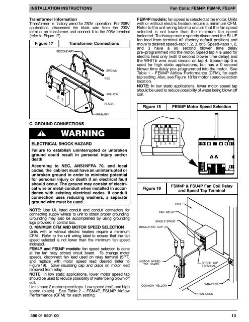
<strong>INSTALLATION</strong> <strong>INSTRUCTIONS</strong>Transformer InformationTransformer is factory wired for 230V operation. For 208Vapplications, disconnect the black wire from the 230Vterminal on transformer and connect it to the 208V terminal(refer to Figure 17).Figure 17CSECONDARY208230Transformer ConnectionsBROWNREDYELLOWBLACK<strong>Fan</strong> <strong>Coils</strong>: <strong>FEM4P</strong>, FSM4P, FSU4P<strong>FEM4P</strong> models: fan speed is selected at the motor. Unitswith or without electric heaters require a minimum CFM.Refer to the unit wiring label to ensure that the fan speedselected is not lower than the minimum fan speedindicated. To change motor speeds disconnect the BLUEfan lead from terminal #2 (factory default position) andmove to desired speed--tap; 1, 2, 3, or 5. Speed--taps 1, 2,and 3 have a 90 second blower time delaypre--programmed into the motor. Speed tap 4 is used forelectric heat only (with 0 second blower time delay) andthe WHITE wire must remain on tap 4. Speed--tap 5 isused for high static applications, but has a 0 secondblower time delay pre--programmed into the motor. SeeTable 1 -- <strong>FEM4P</strong> Airflow Performance (CFM), for eachtap setting. Also, see Figure 18 for motor speed selectionlocation.NOTE: In low static applications, lower motor speed tapshould be used to reduce possibility of water being blown offcoil.Figure 18<strong>FEM4P</strong> Motor Speed SelectionPRIMARYC. GROUND CONNECTIONS! WARNINGELECTRICAL SHOCK HAZARDFailure to establish uninterrupted or unbrokenground could result in personal injury and/ordeath.According to NEC, ANSI/NFPA 70, and localcodes, the cabinet must have an uninterrupted orunbroken ground in order to minimize potentialfor personal injury or death if an electrical faultshould occur. The ground may consist of electricalwire or metal conduit when installed in accordancewith existing electrical codes. If conduitconnection uses reducing washers, a separateground wire must be used.NOTE: Use UL listed conduit and conduit connectors forconnecting supply wire(s) to unit to obtain proper grounding.Grounding may also be accomplished by using groundinglugs provided in control box.D. MINIMUM CFM AND MOTOR SPEED SELECTIONUnits with or without electric heaters require a minimumCFM. Refer to the unit wiring label to ensure that the fanspeed selected is not lower than the minimum fan speedindicated.FSM4P and FSU4P models: fan speed selection is doneat the fan relay printed circuit board. To change motorspeeds, disconnect fan lead used on relay terminal (SPT)and replace with motor speed lead desired (refer toFigure 19). Save insulating cap and place on motor leadremoved from relay.NOTE: In low static applications, lower motor speed tapshould be used to reduce possibility of water being blown offcoil.Units have 2 motor speed taps. Low speed (red) and highspeed (black). See Table 2 -- FSM4P, FSU4P AirflowPerformance (CFM) for each setting.Figure 191 2 3 4 5INSULATING CAP (2)MOTOR SPEEDTAP LEADSFAN RELAYSINGLE SPADECOMMON YELLOWFSM4P & FSU4P <strong>Fan</strong> Coil Relayand Speed Tap TerminalPCBSPEED TAPTERMINALWRAPPERFAN DECK496 01 5501 00 13