INSTALLATION INSTRUCTIONS Fan Coils FEM4P ... - PROFLO
INSTALLATION INSTRUCTIONS Fan Coils FEM4P ... - PROFLO
INSTALLATION INSTRUCTIONS Fan Coils FEM4P ... - PROFLO

You also want an ePaper? Increase the reach of your titles
YUMPU automatically turns print PDFs into web optimized ePapers that Google loves.
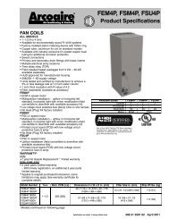
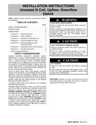
<strong>INSTALLATION</strong> <strong>INSTRUCTIONS</strong>AIR DUCTSConnect supply--air duct over the outside of ¾” flangesprovided on supply--air opening. Secure duct to flangeusing proper fasteners for type of duct used, and sealduct--to--unit joint.Use flexible connectors between duct work and unit toprevent transmission of vibration. When electric heater isinstalled, use heat--resistant material for flexibleconnector between duct work and unit at dischargeconnection. Duct work passing through unconditionedspace must be insulated and covered with vapor barrier.ELECTRICAL CONNECTIONSFSM4P and FSU4P <strong>Fan</strong> Coil models utilize a printedcircuit board (PCB) which has a low voltage circuitprotective fuse (5 amp), fan motor speed tap terminal(SPT), and time--delay relay (TDR). To disable the TDRfeature, snip the jumper wire JW1 (refer to Figure 10).<strong>FEM4P</strong> <strong>Fan</strong> Coil models do not have a printed circuit board(PCB), they have a low voltage circuit protective fuse (3amp) inline on the wire harness. Speed selections are madeat the fan motor with the Blue wire. The motor ispreprogrammed with the time--delay circuit on some of thespeed taps. (See Section D)Before proceeding with electrical connections, make certainthat supply voltage, frequency, phase, and circuit ampacityare as specified on the unit rating plate. See unit wiring labelfor proper field high and low voltage wiring.! WARNINGELECTRICAL SHOCK or UNIT DAMAGE HAZARDFailure to follow this warning could result in personalinjury, death, and/or unit damage.If a disconnect switch is to be mounted on unit, selecta location where drill and fasteners will notcontact electrical or refrigeration components.<strong>Fan</strong> <strong>Coils</strong>: <strong>FEM4P</strong>, FSM4P, FSU4PDuct work Acoustical TreatmentMetal duct systems that do not have a 90 degree elbowand 10 feet of main duct before first branch takeoff mayrequire internal acoustical insulation lining. As analternative, fibrous duct work may be used if constructedand installed in accordance with the latest edition ofSMACNA construction standard on fibrous glass ducts.Both acoustical lining and fibrous duct work shall complywith National Fire Protection Association as tested by ULStandard 181 for Class 1 air ducts.Make all electrical connections in accordance with theNEC and any local codes or ordinances that may apply.Use copper wire only. The unit must have a separatebranch electric circuit with a field--supplied disconnectswitch located within sight from and readily accessiblefrom the unit.NOTE: When a pull--out type disconnect is removed fromthe unit, only the Load side of the circuit is de--energized.The Line side remains live until the main (remote)disconnect is turned off.! WARNINGELECTRICAL SHOCK HAZARDFailure to follow this warning could result in personalinjury or death.Turn off the main (remote) disconnect device beforeworking on incoming (field) wiring .Incoming (field) wires on the line side of the disconnectfound in the fan coil unit remain live, evenwhen the pull -out is removed. Service and maintenanceto incoming (field) wiring cannot be performeduntil the main disconnect switch (remoteto the unit) is turned off.Figure 10<strong>Fan</strong> Coil Printed Circuit BoardFSM4P, FSU4P5JW110 496 01 5501 00