AES 124-paper - Menno van der Veen
AES 124-paper - Menno van der Veen
AES 124-paper - Menno van der Veen
- No tags were found...

You also want an ePaper? Increase the reach of your titles
YUMPU automatically turns print PDFs into web optimized ePapers that Google loves.
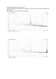
Van <strong>der</strong> <strong>Veen</strong> et. al.Non-Linear distortions in capacitors4. NUMERICAL SOLUTIONSWith the differential equation 3 and theelectrical circuit equations 4 to 6 a set of differentialequations is created which needs to be solved.However, the total system is non-linear, so astandard analytical solution is not applicable.Therefore we developed a numerical approach,which is discussed below.Because of space limitations, we will onlygive a course outline of the numerical solver. It is awell-established solving technique using timediscretisation and no voltage and currentdiscretisations. The pitfall is that the timediscretisation introduces delays between thedifferent <strong>der</strong>ivatives (first and second or<strong>der</strong>) andthus a deviation between the analytical andnumerical differential equations which are solved.The obvious solution is to use very small timesteps, but this can lead to a large volume ofcalculations and –far more sneaky- to round-offerrors in the changes of the signal to benumerically integrated. This will lead to erroneousresults. Finding the correct balance between thetwo conflicting requirements is part of the solverand this has been verified by applying the solver toa linear second or<strong>der</strong> differential equation (whichcan be solved analytically) and subsequentlycomparing the analytical and numerical solutions.The results of this verification are presented infigures 2 and 3 and it is clear that the results areindistinguishable. The results of the solver can betrusted such that it will provide the consequencesof the non-linear effects as the model introduces.5. RESULTS AND DISCUSSIONWhen a sine wave is sent through thehigh-pass filter as mentioned above, the value ofthe swinging capacitor will vary with the voltageacross the capacitor. As a consequence, thecurrent, flowing through the load resistor R L will notbe a pure sine wave, but will be –relativelyspeaking- larger when the voltage across thecapacitor is larger. An extreme case, in which theplate distance variation equals 3.5 %, was chosento illustrate the effect as the distortion in the currentis visible without further analysis. It also shows thatthe phase of the distortion products is influencedby the phase across the capacitor. Note that the“cut-off” frequency is no longer a constant as thecapacitance is not a constant!When an AC signal is applied to such afilter, the distortion products are –as a firstapproximation- proportional to the square of theinput voltage. This means that the effects increasestrongly with the signal strength. As it is likely thatthere will be a relation with the maximum voltage acapacitor can handle. the effects are likely to bestrong in passive cross-over loudspeaker filterswhere strong signals are used.6. INTERMODULATION IN CROSS-OVERFILTERSThe non-linear properties as outlinedabove become apparent in cross-over filters wheremostly large AC signals are applied in combinationwith large capacitors (both in capacitance and size)because of the large currents which flow through it,compared to e.g. the electronics in a controlamplifier. Such capacitors will –in general- showthe non-linear behaviour clearly and it is thereforenot really surprising that cross-over filters are oftenmentioned when the audible properties ofcapacitors are discussed. Therefore a typical casewas modelled: two pure sine waves were used asinput signal. The frequency of the high frequencywas roughly equal to the cut-off frequency of thehigh-pass filter, the frequency of the low frequencycomponent is 1/8 of the frequency of the highfrequency component and its amplitude is 4 timesthe amplitude of the high frequency component.The initial input frequencies can be identified atfrequencies “1” and “8” in figure 5. Note that theamplitude of the low-frequency signal has beenreduced as can be expected by the action of ahigh-pass filter. The results, presented in fig. 5, canbe called stunning. Although the calculation isbased on the model as presented above, the clearpresence of a large number of intermodulationproducts with a significant signal strength isworrying to say the least. It is obvious that sucheffects can clearly introduce audible differencesbetween different types of capacitors. But now thatwe have unveiled the un<strong>der</strong>lying cause of theproblem, an objective way to determine the audibleproperties of different types of capacitors can be<strong>AES</strong> <strong>124</strong>th Convention, Amsterdam, The Netherlands, 2008 May 17–20Page 3 of 7