Create successful ePaper yourself
Turn your PDF publications into a flip-book with our unique Google optimized e-Paper software.
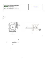
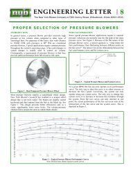
NON-STANDARD AIR KITSWhen the system plenum cannot be designedto accommodate pre-designed, st<strong>and</strong>ard <strong>Air</strong><strong>Kits</strong> [from Chart VII], <strong>Air</strong> <strong>Kits</strong> with nonst<strong>and</strong>ardshaft sizes <strong>and</strong> wheel bores may beselected using the shaft safe speed curves onpages 11 to 14.F1"BWA M 2A M ABFKF1"BAWMABFKThe curves show maximum shaft safe speedsat 70°F. for all possible bearing-center distances<strong>and</strong> <strong>Air</strong> Kit combinations. Final selectionsmust be corrected for operating temperature.Curves are based on proper spacing of fansbetween walls [A on each side <strong>and</strong> 2A betweenfans]. Curves cannot be extended to obtainselections not shown.Bearing centersJHShaft<strong>Double</strong> <strong>Air</strong> KitBearing centersJShaftH<strong>Single</strong> <strong>Air</strong> KitSee page 4 for A dimension criteria.See page 15 for F, K, <strong>and</strong> M dimension criteria.HOW TO SELECT A NON-STANDARD AIR KITPROCEDURES STEPS EXAMPLESummary.<strong>Air</strong> Kit size <strong>and</strong> model have been selected from the example on page 6.Plenum effect has been calculated <strong>and</strong> speed <strong>and</strong> BHP determined. Wheelsafe speed at 700°F had been checked.Calculate bearing-center distance.Select shaft size <strong>and</strong> check shaftsafe speed at operating temperature.Final selection.Inside wall-to-wall distance is 54”. Wall thickness is 4” for a total W of 62”.Use F dimension from Chart VII for <strong>Double</strong> <strong>Air</strong> Kit with closest W dimension.F = 3”. Bearing centers for using curves is 65”.Using the X15B-2 graph, draw a horizon line from 65” <strong>and</strong> a vertical line from1197 RPM. Correct selection is the curve that is above the intersection point...15B35-2 with a maximum safe speed of 1310 at 70°F. [continue the horizontalline], 1310 x .92 [Chart VI @700°F.] = 1205 RPM.An X15B35-2 <strong>Air</strong> Kit with cooler wheels.120X12B-1 SINGLE AIR KIT120X12B-2 DOUBLE AIR KIT110110Bearing centers [Inches]10090807060504012B47-112B43-112B39-112B35-112B31-112B27-112B23-1Bearing centers [Inches]1009080706012B23-212B27-212B31-212B35-212B47-212B43-212B39-2305020400 500 600 700 800 900 1000 1100 1200 1300 1400 1500 1600 1700 1800 1900 2000 2100 2200Shaft safe speed [RPM]40400 500 600 700 800 900 1000 1100 1200 1300 1400 1500 1600 1700 1800 1900 2000 2100 2200Shaft safe speed [RPM]PAGE 11