
You also want an ePaper? Increase the reach of your titles
YUMPU automatically turns print PDFs into web optimized ePapers that Google loves.
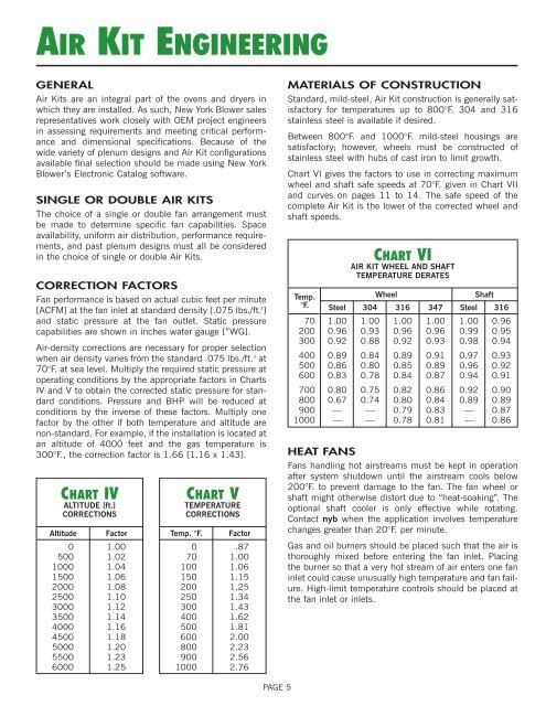
AIR KIT ENGINEERINGGENERAL<strong>Air</strong> <strong>Kits</strong> are an integral part of the ovens <strong>and</strong> dryers inwhich they are installed. As such, <strong>New</strong> <strong>York</strong> <strong>Blower</strong> salesrepresentatives work closely with OEM project engineersin assessing requirements <strong>and</strong> meeting critical performance<strong>and</strong> dimensional specifications. Because of thewide variety of plenum designs <strong>and</strong> <strong>Air</strong> Kit configurationsavailable final selection should be made using <strong>New</strong> <strong>York</strong><strong>Blower</strong>’s Electronic Catalog software.SINGLE OR DOUBLE AIR KITSThe choice of a single or double fan arrangement mustbe made to determine specific fan capabilities. Spaceavailability, uniform air distribution, performance requirements,<strong>and</strong> past plenum designs must all be consideredin the choice of single or double <strong>Air</strong> <strong>Kits</strong>.CORRECTION FACTORSFan performance is based on actual cubic feet per minute[ACFM] at the fan inlet at st<strong>and</strong>ard density [.075 lbs./ft. 3 ]<strong>and</strong> static pressure at the fan outlet. Static pressurecapabilities are shown in inches water gauge [”WG].<strong>Air</strong>-density corrections are necessary for proper selectionwhen air density varies from the st<strong>and</strong>ard .075 lbs./ft. 3 at70°F. at sea level. Multiply the required static pressure atoperating conditions by the appropriate factors in ChartsIV <strong>and</strong> V to obtain the corrected static pressure for st<strong>and</strong>ardconditions. Pressure <strong>and</strong> BHP will be reduced atconditions by the inverse of these factors. Multiply onefactor by the other if both temperature <strong>and</strong> altitude arenon-st<strong>and</strong>ard. For example, if the installation is located atan altitude of 4000 feet <strong>and</strong> the gas temperature is300°F., the correction factor is 1.66 [1.16 x 1.43].CHART IVALTITUDE [ft.]CORRECTIONSAltitude Factor0 1.00500 1.021000 1.041500 1.062000 1.082500 1.103000 1.123500 1.144000 1.164500 1.185000 1.205500 1.236000 1.25CHART VTEMPERATURECORRECTIONSTemp. °F. Factor0 .8770 1.00100 1.06150 1.15200 1.25250 1.34300 1.43400 1.62500 1.81600 2.00800 2.23900 2.561000 2.76MATERIALS OF CONSTRUCTIONSt<strong>and</strong>ard, mild-steel, <strong>Air</strong> Kit construction is generally satisfactoryfor temperatures up to 800°F. 304 <strong>and</strong> 316stainless steel is available if desired.Between 800°F. <strong>and</strong> 1000°F. mild-steel housings aresatisfactory; however, wheels must be constructed ofstainless steel with hubs of cast iron to limit growth.Chart VI gives the factors to use in correcting maximumwheel <strong>and</strong> shaft safe speeds at 70°F. given in Chart VII<strong>and</strong> curves on pages 11 to 14. The safe speed of thecomplete <strong>Air</strong> Kit is the lower of the corrected wheel <strong>and</strong>shaft speeds.Temp.°F.CHART VIAIR KIT WHEEL AND SHAFTTEMPERATURE DERATESWheelShaftSteel 304 316 347 Steel 31670 1.00 1.00 1.00 1.00 1.00 0.96200 0.96 0.93 0.96 0.96 0.99 0.95300 0.92 0.88 0.92 0.93 0.98 0.94400 0.89 0.84 0.89 0.91 0.97 0.93500 0.86 0.80 0.85 0.89 0.96 0.92600 0.83 0.78 0.84 0.87 0.94 0.91700 0.80 0.75 0.82 0.86 0.92 0.90800 0.67 0.74 0.80 0.84 0.89 0.89900 — — 0.79 0.83 — 0.871000 — — 0.78 0.81 — 0.86HEAT FANSFans h<strong>and</strong>ling hot airstreams must be kept in operationafter system shutdown until the airstream cools below200°F. to prevent damage to the fan. The fan wheel orshaft might otherwise distort due to “heat-soaking”. Theoptional shaft cooler is only effective while rotating.Contact nyb when the application involves temperaturechanges greater than 20°F. per minute.Gas <strong>and</strong> oil burners should be placed such that the air isthoroughly mixed before entering the fan inlet. Placingthe burner so that a very hot stream of air enters one faninlet could cause unusually high temperature <strong>and</strong> fan failure.High-limit temperature controls should be placed atthe fan inlet or inlets.PAGE 5