Ionized physical vapor deposition of integrated circuit interconnects*
Ionized physical vapor deposition of integrated circuit interconnects*
Ionized physical vapor deposition of integrated circuit interconnects*

Create successful ePaper yourself
Turn your PDF publications into a flip-book with our unique Google optimized e-Paper software.
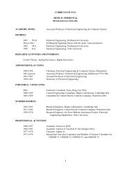
Phys. Plasmas, Vol. 5, No. 5, May 1998J. Hopwood1625FIG. 1. A partial cross section <strong>of</strong> a simplified <strong>integrated</strong> <strong>circuit</strong>. The expandedview shows a via that is lined with Ti and TiN and subsequentlyfilled with W or Al. Future materials are indicated in parentheses.to the thickness deposited on the top surface <strong>of</strong> the ILD.Next the via receives a barrier layer <strong>of</strong> TiN that protects theILD from corrosive effects <strong>of</strong> WF 6 during chemical <strong>vapor</strong><strong>deposition</strong> <strong>of</strong> the tungsten via plug. Alternately, if aluminumis used as the plug material, the TiN acts as a wetting layerthat allows the sputtered aluminum to be reflowed 3 into thevia at elevated temperatures. In both cases, the TiN acts as adiffusion barrier between the plug and the ILD. The diffusionbarrier must be conformal to the via and it should be asthin as possible so that very little cross sectional area is occupiedby the somewhat resistive barrier material. Finally thelow-resistivity via plug material is deposited. This material isprogressing from W to Al, and eventually Cu. The overburden<strong>of</strong> metal present on the ILD after <strong>deposition</strong> <strong>of</strong> the plugis removed by chemical-mechanical polishing. In the singledamascene process, these step are repeated for the <strong>deposition</strong><strong>of</strong> the metal lines above the vias. A future alternative is thedual damascene process 4 in which the via and metal levelsare etched simultaneously. Then both the via and the metalline are filled with conducting materials and planarized byCMP in the final step. The dual damascene process reducesthe number <strong>of</strong> processing steps needed to fabricate a metallevel, but the requirements on the <strong>deposition</strong> process are considerablymore stringent.Aluminum-0.5% Cu metallization is projected to be replacedby pure copper. 5 Copper has a lower bulk electricalresistivity than AlCu 1.7 vs 3.2 -cm so that the interconnectdelay time RC may be decreased. Equally importantis copper’s ability to conduct higher current densitiesthan AlCu without failure <strong>of</strong> the thin lines due to electromigration<strong>of</strong> the metal atoms. Since copper does not form aself-limiting oxide, copper interconnects will need to becompletely enveloped in a passivating diffusion barrier, mostlikely consisting <strong>of</strong> Ta and TaN layers.Although many technological challenges exist in the areas<strong>of</strong> lithography, low-permittivity dielectric materials andvia etching, this paper will focus on the directional <strong>deposition</strong><strong>of</strong> barrier and plug materials. There are three potentialmethods <strong>of</strong> interconnect <strong>deposition</strong>: Physical <strong>vapor</strong> <strong>deposition</strong>PVD, chemical <strong>vapor</strong> <strong>deposition</strong> CVD, and electroplating.The CVD methods use elevated temperatures orplasma 6 to dissociate precursor species. Filling or lining <strong>of</strong>high aspect ratio features is accomplished by fragmented precursorspecies with low sticking coefficients that are capable<strong>of</strong> reaching and depositing at the bottom <strong>of</strong> deep, narrowopenings. While highly conformal films can be depositedusing CVD, the cost and toxicity <strong>of</strong> the precursor materialsremains an issue. Plating is also an effective way <strong>of</strong> fillinghigh AR features. The plating baths, however, can be difficultto maintain, present a liquid waste hazard, and representa departure from the semiconductor industry’s preference fordry processing. PVD, and in particular sputtering, has longbeen the workhorse <strong>of</strong> the industry. The fundamental problemwith sputtering, however, is the sputtered species areejected from the solid target with a cos n () angulardistribution 7,8 which limits bottom coverage to approximately0.2 in structures with 2:1 ARs. Physical collimation 9<strong>of</strong> the sputtered flux by a honeycomb-shaped filter betweenthe target and wafer improves film conformality by trappingsputtered species with large angle trajectories. Bottomcoverage 10 <strong>of</strong> 2:1 features increases to 0.3–0.4, but the collimatorsignificantly reduces the <strong>deposition</strong> rate and may createparticles that reduce the yield <strong>of</strong> functional ICs.II. IONIZED PHYSICAL VAPOR DEPOSITION „I-PVD…I-PVD is a recent advance in PVD technology thatachieves directional <strong>deposition</strong> <strong>of</strong> metals by ionizing thesputtered or e<strong>vapor</strong>ated metal atoms and collimating theseions with the plasma sheath adjacent to the wafer as shownin Fig. 2. A high electron density (n e 10 11 cm 3 ), inert gasplasma between the target and the wafer is needed to ionizethe metal <strong>vapor</strong>. Strong ionization <strong>of</strong> the metal occurs sincethe electron temperature depends primarily on the ionizationpotential <strong>of</strong> the inert gas 15.7 eV for argon which is muchgreater than that <strong>of</strong> metals 6.0 and 7.7 eV for Al and Cu.The plasma source is commonly an electron cyclotron resonanceplasma 11–13 or inductively coupled plasma. 14–17The average distance that a sputtered neutral will travelbefore being ionized dictates the design <strong>of</strong> an I-PVD system.Simple analysis <strong>of</strong> a sputtered neutral traversing a high densityplasma gives the ionization mean free path 18,19 as iz s /K i n e where s is the velocity <strong>of</strong> the sputtered neutraland K i is the ionization rate constant see below. Atomssputtered from the target exhibit a Thomson distribution 20where the most probable energy is one half the surface bindingenergy (1.5 eV for Al. Therefore, iz 60 cm in anAr plasma where T e 3 eV and n e 510 11 cm 3 . Thisanalysis suggests two methods <strong>of</strong> generating a highly ionized,directional metal flux. First, if the inert gas pressure isquite low, the target-to-wafer distance must be quite long.