1 - Alaska Energy Data Inventory
1 - Alaska Energy Data Inventory
1 - Alaska Energy Data Inventory
- No tags were found...

Create successful ePaper yourself
Turn your PDF publications into a flip-book with our unique Google optimized e-Paper software.
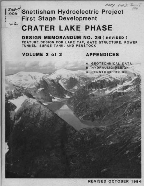
. c-o,.oy t:) ~3 J .-7I ~U~~T Snettisham Hydroelectric Project~ First Stage Developmentv.~ 'CRATER LAKE PHASEDESIGN M-EMORANDUM NO. 26 ( REVISED)FEATURE DESIGN FOR LAKE TAP, GATE STRUCTURE, POWERTUNNEL, SURGE TANK, AND PENSTOCKVOLUME 2 of 2APPENDICES. A. GEOTECHNICAL DATAB. HYDRAULIC DE NC. PENSTOCK DESIGNREVISED OCTOBER 1984
SNETTISHAM PROJECTALASKASECOND STAGE DEVELOPMENTCRATER LAKE PHASEREVISED DESIGN MEMORANDUM NO. 26VOLUME 2 of 2APPENDICES
SYNOPSISThe Long Lake - Crater Lake Division of the Snettisham HydroelectricProject was authorized for construction by Congress in 1961. Volume 1 OfDesign Memorandum No. 26, Main Report, summarizes the post-authorizationstudies conducted to date for the Crater Lake phase, and presents therecommended feature design developed as a result of those studies.The feature design level studies included agency and environmentalcoordination, geotechnical investigations, computer modelling of thepower conduit and its appurtenances, design analyses, a detailed quantitytakeoff and cost estimate, and preparation of feature level drawings.The next level of effort will be preparation of plans and specifications,during which the design of the features will be refined and detailed.The technlcal appendices contained herein present the geotechnical datafrom the pertinent explorations, as well as sample calculations fortunnel support; the design criteria, methodology, constraints, andcalculations for the hydraulic design of all features of this designmemorandum; and the theory for penstock design. This informationsupplements the general overview presented in the Main Report.
ABBREVIATIONSThe following is a list of definitions for abbreviations used in thisreport.acre-ftaveBtuCdcftft2ft3ft/minft/sft3/sft/s2ga 1gal/mingal/yrGWhhhpI, 10ini n/sin/yrKVAkWkWhlb1 b/ft21 b/ft3lb/hrlb/in2alb/in2gMmimi/hrmi2minmoMSLMWMWhpctr/minsVWWyyd 3yrofSource:acre-footaverageBritish thermal unitdegrees Celsiusdirect currentfootsquare footcubic footfoot per minutefoot per secondcubic foot per secondfoot per second squaredgallongallons per minutegallons per yeargigawatt hourhourhorsepowermodified Mercalli intensityinchinch per secondinch per yearkilovoltamperekilowattkilowatt hourpoundpound per square footpound per cubic footpounds per hourpounds per square inch absolutepounds per square inch gageRichter magnitudemilemiles per hoursquare mileminutemonthmean sea levelmegawattmegawatt hourpercentrevolutions per minutesecondvoltwattwater yearcubic yardyeardegree FahrenheitU.S. Government Printing Office Style Manual, January 1973
LOCATION:SNETTISHAM PROJECT, ALASKACRATER LAKE PHASEPERTINENT DATANear the mouth of Speel River, 28 mi southeast of Juneau, <strong>Alaska</strong>.AUTHORIZED:Flood Control Act of 1962, providing for design and construction by theCorps of Engineers and for operation and maintenance by the Department ofthe Interior.PLAN:Construct an underground power conduit from the existing undergroundpowerhouse to Crater Lake. Install an additional turbine and generator inthe powerhouse.PROJECT FEATURES:NOTE:Datum.All elevations cited in this report are in feet and refer to ProjectMSL is 2.9 ft below Project Datum.Elevations of Tide Planes at Speel River with respect to Mean Lower LowWater and Project Datum are as follows:Highest Tide (Estimate)Mean Higher High WaterMean High WaterHalf Tide Level (MSL)Mean Low WaterMean Lower Low WaterLowest Tide (Estimate)MLLW22:""5"15.914.88.21.60.0-5.7PROJECT DATUM11.44.83.7-2.9-9.5-11 .1-16.8Tidal Datum Planes are based on 7 mo (1/65 to 8/65) of automatic gageoperation by USGS.Drainage area, mi2Annual runoff, minimum, acre-ftAnnual runoff, average, acre-ftAnnual runoff, maximum, acre-ftHydrology11.4113,000145,500186,750
ReservoirMaximum observed surface elevation, ft1,019Elevation of natural lake outfall, (full-power pool), ft1,017Elevation of minimum operating pool, ft820Initial active storage capacity, acre-ft81,500Area of reservoir at full pool, acres330Area of reservoir at minimum pool, acres145Lake TapTypeOpen system/wet tunnelSize, ft12 (dia.) by 10Lake bottom elevation at tap, ft799Primary Rock TrapLocation1 ake tapBottom area, ft21,152Volume of tap material contained, yd386Invert elevation, ft753.5 to 761.5Secondary Rock TrapLocation400 ft downstream of lake tapTypeExpanded horseshoe section with excavated invertSi ze, ft20 wide by 11 high by 60 longInvert elevation, ft776Gate StructureLocation200 ft downstream of sec. rock trapTypeService room floor elevation, ftInvert elevation, ftMaximum operating head, ftWet-well in rock1,040789233
Maximum momentary head, ft(during lake tap blast)Service gate, quantityTypeSize, ft295Slide6.8 by 8.5Bulkhead, quantityTypeSize, ftPower Tunnel8.7 by 9.3Modified horseshoeTotal length, ftUnlined length, ftDiameter (modified horseshoe), ftShotcrete lined length, ftConcrete lined length, ftDiameter (circular), ft6,0204,975119201259Final Rock TrapLocationTypeSize, ftStorage capacity, yd 3Invert elevation, ft5,400 ft downstream of gate structureExpanded horseshoe section with excavated invert15 wide by 15 high by 100 long96126 to 109Surge TankLocationType5, 160 ft downstream of gate structurevented vertical shaftDiameter, ft 10Top elevation, ft 1,080Bottom elevation, ft 145.3Power tunnel invert elevation, ft 150.0
Drift tunnel length, ft 60TypeLength, ftSteel penstock inner diameter, ftNumber of additional unitsType of TurbinePenstockPowerhouseUnderground, unencased steel903Vertical FrancisTurbine rated capacity, hp 47,000(based on rated net head, full gate, and generator rated capacity)Generator nameplate rated capacity, KVAAnnual firm output, kWhAverage annual non-firm output, kWhTailwater elevation, ft(1) Maximum net head, ftDischarge at maximum net head, ft3/sPool elevation at maximum net head, ft(2) Design net head (rated net head), ftDischarge at design net head, ft3/sPool elevation at average net head, ft(3) Minimum (critical) net head, ftDischarge at minimum net head, ft3/sPool elevation at minimum net head, ft(4) Maximum discharge (hydraulic capacity), ft3/s(1) Based on generation of 31.05 MW at maximum pool and plantefficiency = 86 pet.634,500105,100,00016,100,00011 .0-12.5990.54301,019945.5300967788.0470820518(2) Based on generation of 20.70 MW at average pool and plantefficiency = 86 pct.-
(3) Based on generation of 27.3 MW (guaranteed output) at minimum pool andplant efficiency = 86 pct.(4) Maximum discharge is based on the Long Lake turbine model with aprototype throat diameter of 51.5 inches, 100 pct wicket gate opening, andgenerator blocked output of 34.5 KVA. This occurs at a net turbine head of912 ft.
A. GEOTECHNICAL DATALIST OF APPENDICESAl Geomechanical AnalysisA2 Drill Hole Summary LogsB. HYDRAULIC DESIGNC. PENSTOCK DESIGNBl Hydraulic Design of Recommended PlanB2 Sample Calculations for Recommended PlanB3 Hydraulic Design of Alternative Plans I and IIB4 Hydraulic Design of Alternative Plans IIIClC2Analysis of Confined Penstocks for External HeadStress Analysis of Steel Liners for Penstock Embeddedin Rock
APPENDIX AGEOTECHNICAL DATAAlA2GEOMECHANICAL ANALYSISDRILL HOLE SUMMARY LOGS
APPENDIX AlGEOMECHANICAL ANALYSIS
A. "AVERAGE" FAULT CONDITION.GEOMECHANICAL ANALYSISAnalysis of rock conditions using both the Bieniawski and NGI systemsshows support requirements to be minimal. For the "average" faultcondition, the Bieniawski Rock Mass Rating (RMR) is 71.5 (class II, goodrock) with a maximum unsupported span of 68 ft and a stand up time of 20 mo.The NGI "Q" system, using an average rock quality designation (RQD) of85, gives a Q of 34 and an equivalent dimension of 2.1 indicatinguntensioned roof dowels spotted as necessary. More conservatively, thissystem gives a maximum unsupported span of 49 ft and a stand up time ofapproximately 8 yr.B. "WORST" FAULT CONDITION.Another analysis was made using the worst possible situationencountered in explorations and assuming that this represents the conditionof the five major faults at tunnel elevation.The Bieniawski rock mass rating is 22 to 27, Class IV, poor rock. Thelower number represents the actual fault, the higher number is for rocksurrounding and affected by faulting. The NGI system gives a "Q" of 0.129to 0.0143, the lower number representing the fault.Indicated support requirements are tensioned bolts spaced 3.3 ft oncenter and 2 inches of mesh reinforced shotcrete for the surrounding rock.The fault will require 6 inches of mesh reinforced shotcrete. While noroof bolts are indicated, mine ties and bolts will be used as conditionswarrant.Since latest research indicates mesh reinforcement has problems, fiberreinforced shotcrete will be specified.C. SAMPLE CALCULATION.This analysis is for the "average" condition in the following faultedareas:CliffsideHi 1ltopT1 i ngitTsimshianPenstockSta. 10+80Sta. 11+60 to 11+95Sta. 52+80 to 56+30Sta. 74+80
1. Bieniawski SystemThe Bieniawski rock mass rating of 71.5, Class II is arrived by:(a) Rock unconfined compression strength of 13,000 to14,000 lb/in2 results in a RMR of 11.of 20.(b) RQD=85 results in a RMR of 18.(c)Joint spacing of generally 1 ft or greater results in a RMR(d) Joint condition: rough surfaces, little or no separation,and hard joint wall, results in a RMR of 21.(e) Groundwater: nearly dry results in a RMR of 9.The total of factors a-e. yields an unadjusted RMR of 79.Adjustments to RMR:Faults dip between 70 0 and 90 0 and strike sub-parrallel to tunnelaxis. This is a fair to unfavorable situation which results in RMR of-7.5.The net RMR is 71.5, Class II, good rock, which means that anunsupported span of 11 ft gives a standup time of approximately 6,000 h(250 d). Support requirements are occasional roof bolts with wire meshif needed and 2 inches of shotcrete as conditions warrant.where:2. NGI ugll S,z:stemThe NGI "Q" system is determined by using the formulaQ =Q = rock qualityC:D)(J~r~ fs~~)RQD = the rock quality designation of Deere et. al.I n = the joint set numberJr = the joint roughness numberJa = the joint alteration numberJw = the joint water reduction factorSRF = the stress reduction factor.
For the existing conditions the following values are applicable:ROD = 85 taken as an average of fault affected rocks.In = 3; one set (the fault) plus random joints.Jr = 3; rough and irregular.Ja = 1; generally unaltered walls with surface staining (iron) only.(Will occasionally increase to 2 where chlorite or seracite arenoted.)Jw = 1; dry to very minor inflows.SRF = 2.5; single weakness zones containing clay, etc., depth greaterthan 165 ft.o = 85 • 3 • 1 = 34-3- -1 2.5Excavation support ratio (ESR) is 1.6; water tunnel.Equivalent Dimension = Tunnel diameter (meters)ESRMaximum unsupport span = 2 (ESR) 00•4 = 43 ft.O. 1188a support group of 13 through 16.RQD J r 1 . Span 43 ft= 28.33j _ = = = 27 ft-J-J } ESRnn1.6The above indicates intensioned roof bolts at 5 to 6.5 ft centers.
APPENDIX A2DRILL HOLE SUMMARY LOGS
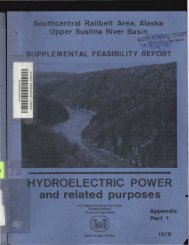
SUMMARY ."'OGHOLE Nv.N 93 61':' I SHEET 1 OF 3DH 98 E 86,377 I SURFACE El.EV. 102':'.7PROJECT Snettisham (Crater Lak pRILL DATES' START 30 Sept n. COMPo 8 Oct 72DEPTH OF' HOLE ~~o ft. D€PTH 01 OVERBURDEN 0.85 ft. DIAM. OF HOLE Nx CoreROCK DRILLED : •.. IS f c:. CORE RECOVERED LOO~;ANGLE FROM VERT. 1)0AZIMUTH FROM NORTHDISTANCES: VERTICAL. ~ HORIZONTAL,~EJ..iV. O£PTH LOGl-J;;·~. (). 0DESCRIPTION OF MATERIALSSurface~COA!% RECOVERY 100~~CO""UD BY,Cldvton RasmussenREMARKSDATE/Core lengths0.1 to ~.D ft.--992.733.) core showed minor high anglejointin~. Core below 33.9 ft.showed no natural joints20'-30'; pressure test -water flowing to DH-I02.-Lost circu~...lti,'n 32 to33 ft. ::'ack:'L,'", J3 [,)-35 ft.I Core lengths0.2 to J.J Ct.Cc)re leni1;ths1.0 to j.O tt.---------\~,)r,~ tengths..:. ,) ~() 5.0-:"~·'or", tcr ... r ..APR: 66 .'IIII MOL E NO. J!, eli;
SUMMARY LOG N 93614 1 ~rrT ? OF "HOLE NO~ nu QQ ~"," .. IA E 86377 I SURFACE ELEV 1024.7PROJECT DRILL OATES· START 30 SEPT 72 COMP. 8 OCT72DEPTH OF HOLE 220.0 FT. O€PTH OfF 0YER8URDENO. 85 FTDIAM. (:# HOLENX COREROCK DRILLE0 21 9. 15 FT. CORE RECOVERED 219.15 FT. % RECOVERY 100ANGLE FROM VERT. AZIMUTH FROM NORTH COMPIL.£D BY. DAT!DISTANCES: VERTlCAL. ~ HOflUZONTAL. CLAYTON RASMUSSO~~ELEV. [)[PTH LOG DESCRIPTION OF MATERIALS1110CORl ""Quartz Diorite- as aboveREMARKSCore lengths2.0 to 5.0 ft.Carr lengths0.3 to 3.5 ft.----Core lengths::J.5 to 5.0 ft.--Quartz Diorite-------Core lengthsJ . 5 to 2.:J ft.--~':_·;_~_'_~_~_M __1_rr_ ••QUclrtz 13i ori te-.... ' .... :,.-..'. .._;_)_'~_·_· ~P~R~O~J~E~C~T_~~s~n~e~t~ti~s~h~am~(~c~'~~a~t~~'r~L~a~ke~~. __·_; __-__ ·~t~:~~·~~·=L~E~~~O~)~~~~al~Q·_·--Jr
SUMMARY LOG N 93614 1 ~H~~T3 Of 3HOLE NO. nu aQ .~~+. E 86377 -rSURFAC£ ELEV.1024.7PROJECTSnettisham (Crater Lake DRILL DATES' START 3 0 SEPT 72 COMP.8 OCT 72DEPTH OF HOLE 2 2 0 • 0 FT. DEPTH ~ OVERBURDEN 0.85 FTDIAM. ~ HOLENX COREROCK DRILLED2 19 . 85 FT. CORE RECOVERED 219.15 FT. % RECOVERY 100ANGLE FROM VERT. AZIMUTH FROM NORTH COMAUD BY, OATEDISTANCE S: VERTICAL, ~ HORIZONTAL.C~AYTONRASMUSSONDESCRIPTION OFMATERIALSREMARKSQuartz Oiorite- as aboveCore 1 engthso .5 to 2.0 ft.804.7,Core lengths0.1 to 2.0 ft---I, ----r -1--Ii--1~-i...:-ji~"1J -4~~~.....;-j-j-- -.- ...I ~,Bottom of HoleDEPTH 220.0 FT.OVERBURDEN 0.85 FT.ROCK DRILLED 219.15 :~-I.CORE RECOVERED 219.1) FT.CORE RECOVERED 100ELEV. OF BOTTOM 804.7IPressure Test ResultsI From To K(XlO- S )20' 30' 333.9JO' 40 ' 1280.840' SO' 138.1jO' 210' 0.0-------- ------N PA Form 7(T tlAPR. 66 .1PROJECTSnettisnam (Crater Lake)I, HOLE NO. n~ 00
ltUMMARY L.OG N 95.473 SHEET 1 OF 401 E NO. nh QQ E Q1 t::.n7 I cu·_- El.EV.I063.:5PROJECT Snettisham (Crate Lake~ DRILL OATES I START 27 SEP 72 COMPo 9 OCT 72DEPTH 0' HOLE 350 . 0 FT DEPTH OF 0VER8URO£H 4 . 0 FT. Of A ... OF HOLEt..x COREROCK DRILLED 346.0 FT. CORE RECOVERED 346.0 % RECOVERY 100ANGLE FROM VERT. 0° AZIMUTH FROM NORTH COMPIUD BY. OAT!DISTANCES: vamc~ ~- HOftIZONTAL __ Clayton ~asmussenIIUI'MIC ...ELEV. D£PTH DESCRIPTION OF MATERIALSLOGREMARKS11063. 00 SurfaceCOR!~Q59 4.0Overburden, organic and-oouldersI~' -,Too of Rock -:,,\\; \-:I;"~ ,Core lengths10 "' "1 I_~" Quartz Diorite, black and0.1 to 1.0 ft.-1"1" \~,/:;, .jhite, hard and fresh wi th ---_ -..,/,1.....,_.....,-Sneissic banding and minor I,-i" i"intingL,I,-\- -';~\ -.......... 1-~,-; ~\20./, ..-,,1/--,\......,~I- -i.....\Core lengths -').1 to 5.0 ftI):-=./'.....- -.;~:.:..'; --:..':,'\.:\-~,30 -~'-I!,- I ~"\ -f'/ '"/1-~,/~J;025 "'-'1 38 to 40 ft. high angle023 - ~.711~ ,_ .... , joint -....., -,'; Core lengths4044 to 49 ft high ang 1 e0.1 to 1.0 ft- -,; jOint I-~ ""2,Qua rtz Di oriteI019 -t\,'-II Core 1 engths-, ::.' - 0.1 to 1.0 ft014 50 ... '--~} .. I I",I, _-,- I!.I" ....\">, " ;/ --k...'/I~/_-):-~~60 ~-'),~-..t", ...--I"~~ -~:-:";,Core lengths.... ',,~/, 0.3 to J 5 ft,,'- - 68 to 71 ft. hiah angle-~ ....",/\joi nt70 '",\1---~Core lengths..... -/-i' ,< 0.3 to 0.5 ft ...J /., ...... ~"..... r .../,Q5 \.~ -J'" I' ..992 - ,~/'//I80 ' '\' Quartz Diorite--t.:,\ '...... 1\" -t'-/:··..;, , ...., /,~...../ ....~,.~/,~ ~... ,......,. ....-I.,;./" -........~ ~-'ICore 1 engthsqo ~,~ " ) . 1 to .1,J- --:)"'/~ ~..;..~ -:~~ \/,"" I-'--,',/i ..... '\ ,- -l:# ",--:f_\'v"I' ,I ,~~63 .3, ,190 ~:.\~~::: .-., . j J.\"; .... . .APR. 66 • . PROJECT ~netti sham (Crater ~dic.e) HOLE NO. DH 99.- ,;ePA ,. ~:et; . . ' ... .- , . :..J-
SUMMARY LOG95473H 0 LEN DH 99 9 1607~ROJECTSnettisham (Crater Lak )DRILL DATESI START 27 SEP 72D€JI'T1of OF HOLE3 50.0 FT. DEPTH 01 OVERBURDEN 4.0 F TROCK DRILLED 346. OFT. CORE RECOVEREDANGLE FROM VERT.AZIMUTH FROM NORTH. HORIZONTALDESCRIPTION 0' MATERIALSQuartz Diorite - as above34('..0~COR!DIAM.OI HOLENx CORE% RECOVERY IonCO ..... UD BY.CL~YTONREMARKSCore lengths0.1 to 4.0 ft.DAT!RASMUSSON950944113 to 119 ft. 2 high anglejointsCore lengthsO.ltoO.5ft.927136 to 136.5 ft. ~igh angle jointCore lengths0.3 to 2.0 f t.Quartz l:lioriteCore 1 enqthso 05 to 1.2 ft.907906156 to 157 ft. high angle jointCore lenqnts0.2 to 2. Oft.29:::171 to 172 ft. hiqh angle jOintJuartz 8ioriteNPA Fo,,,, 7"' fl'APR. 66 " ••PROJECT Snettisham (CrHerHOL E NO.DH 99
N 95473 t SHEET 30f4ltU~!r N'cfG DH 99 E 91607 lSURfAC£ El.EV.1063. 3PROJE:C~nettisham (Crater Lak.el. DRILL DATES' START 27 SEP 72 COMPo 9 OCT 72DU'tM 0' HIOLl350. 0 FT D!P'M OP'~D€N 4.0 FT. OtAM. OP' HOL~x COREROCK DRILLED 346.0 FT. CORE: RECOVERED 3Lh.0 ... RECOVERY 100ANGLE FROM VERT. AZIMUTH FROM NORTH COWtUD BY. DATE=EL~. IO£PTHg 6) . _ 200"DISTANCES: VERTICAl. i HORIZ0"'TAL~ CLAYTON RASMUSSON...DESCRIPTION OF MATERIALSREMARKSCOA!.Quartz Diorite -as aboveCore lengths0.2 to 2.0 ft.---Core lenoths'J. ~ to 3. :: ft.-IICore lenqtns0.1 to'1
SUMMARY LOG N 95473 I SWFFT 4 OF 4HOLE NO~ llH 99 E 916071SURFA~ ~L~V. 1063.3PROJECT Snettisilam (Crater LakFI1DReLL DATES' START 27 SEPT 72 COMPo 9 OCT 72DEPTH 0' HOLE 350.0 IT 01:".,. ~ OV£RBURD!N 4.0 FT DeA ... ~ HOLENX COREROCK DRILLED 346.0 FT CORE RECOVERED J46 . .J % RECOVERY ionANGLE FROM VERT. AZiMUTH FROM NORTH COMPtUD BY. DATEDISTANCES' VEfffICAL. ~ HORIZONTAL.CLAYTON RASMUSSEN...DESCRIPTION OF MATERIALS REMARKSCOA!740Quartz Diorit~ - as above316 to 313 ft. ilign angle joint319 to 319.5 ft. high anglecrossed jOints323 to 324 ft. high angle joint325 to 326 crusned zoneCore lengths0.1 to 0.8 ft.~ost 30 clrculatlonCore 1 enqtlls -0.1 to 0.3 ft.--------I,]j!iDEPTH OF HOLE 350.0 FTJVERBURDEN JR[LLED 4.0 FT.~OCK CORED 346.0 FT.RECOVERED gg+',ELEV. ~T 30Ti0M 713.3Pressure Test KesuitsFro!!! To K(XiO- 5 )40' 50' 25.950 • 60' 0.060' 70 • 69.1iO' liO' 0.01 [I] • 1~0' 11.912') • 310' 1).1)il() • L~() I 11.'13~() I , I ~h.~J Fl' ;.:..,"") , I), 'J-------'..-.1"iI -..Npj[ Form'· "APR. 66 7f1'lInPROJECT, . ~r HOL ENO. :JH qg-
SUMMARY ."'OGHOLE Nu~ DH 100HNr-__ .,.;.9;;.,;36;.;;;1;;;..1____' SHEET 1 OF 4E 86371 LsURFAC£ ELEV. 1019.6PRO.lECTSnettisna. (Crater Lake~ DRILL DATES' START 11 OCT 72 COMP. 19 OCT 72OU'TM OF HOll' 3113.0 FTDIAM. fJ' HOLE Nx CoreROCK DRILLED JIO.O FT CO"E RECOVERED 310.0 FT ~ RECOVERY 100ANGLE FROM VERT. 350 AZIMUTH FROM NORTH 251 0 COWU..£D BY t DAT!DISTANCES: VERncA&.. .. 254.0 i HORIZONTAL,. 177.6,.,Clavton RasmussenCOAlREMARKS~ELEV. ~~ LOG1019.i uuDE!eRIPTION 0' MATERIALSTop of RockQuartz Diorite. black and white.hard and fresh with Gneissicbandinq and. minor jointingCore lenqtns0.2 to 3. 0 ft.--18 to 29 ft. core breaks every0.3 to 0.5 ft.26 to 26.5 ft. closely brokenlow and high angle fracturing29 to 30 ft. closely broken34 to 36.5 ft. closely broken(low anqle fracturinq)Qua rtz Di oriteCore lenqthsJ. 1 to 2. 0 ft.:ore 1enqths0.05 to 0.5 ft.Some circulation loss23 to 28 ft.Core lengths0.05 to 0 3 f~Core 1 enqthsO.S to 2.5 ft.23 to 60 ft. air bubblesin lake 20+ ft. offsnoreCore 1 engths1.0to4.0ft.--------74.7 ft. hiqh anq1e joint75.0 ft. high angle jointCore lengths0.5 to 3.0 ft.-----L3L...2 .00Ouar~z:Jibri't'eff HOLt NO. Dti 1 QQ--
SUMMARY LOGHOLE NE9361186371Crater Lake DRILL OATES' START11O€PTH 0' HOI..! 310.0 IT DEPTH 01 OVERBURDEN 0.0 DIAM. (6 HOLE NX COREROCK DRILLED310.0 FTCORE RECOVEREDANGLE FROM VERT. 35° AZIMUTH FROM NORTH .251 0DISTANCES: VERTlCAL 254.0 FT. HORIZONTAL 177.'1 ,T...D£SCIilIPTION 0' MATERIALSCOREOuartz Diorite - asabove310.0 FT % RECOVERY 100CO ..... LED BY,DATECLAYTON RASMUSSE~REMARKSCore 1 enatils0.3 to 5.0 ft.11 ~"I t6143 to 145.5 ft. higll anq1e jointsome breakaqeQuartz Diorite GneissCore leoQths0.4 to 1.5 ft.Core lengths0.5 to 2.5 ft.155 to 156 ft. crossed highangle joints with chloritecoat ings162 ft. hiqh angle joint177 to 136 ft. high angle jointsbreakageCore lenqths0.5 to 1.5 ft.= Q r e ell rJ -: t~ 5"r ~, • _ 4" ••• -'HOLE NO. DH 1 C;"\
PROJEC~nettisham (Crater Lake' D"ILL DATES' START 11 OCT 72COMP.19 OCT 72DEPTH OF HOI.! 310.0 IT ~ t::I OWReuttO€M 0.0 FT 01.". r:# HOLE: ~ COREROCK DRillED 310.0 FT CORE RECOVERED 310.0 FT % RECOVERY lOOANGLE FROM VERT. 35 0 AZIMUTH FROM NORTHCOMPIUD BY. DAT!DISTANCES: VERTICAL. 254.0 ; ...,..IZONnL 177.6 CLAYTON RASMUSSENEL.fV O!PTH ~ DESCRIPTION OFLOG35:J.il 200... ATEfUALSQuartz Diorite - as aboveREMARKSCore lengths0.5 to 2.5 ft.220 ft. high angle jOintfracture. sericite coatingsCore lenqths0.3 to 2.5 ft.Core lenoths0.3 to ~.j ft.-----240 to 241.5 crossed high anglefracturesr~o fractures or jOi nts from241.5 to 310.0 ft.Ouartz DioriteCore 1el"othsa . 5 to' 5 . Oft.-----------------------:ore 1 enotrls1.0 to s.n ft.---~uar~Z =i Jr; te. :.) l.l!.'k '-"' ·.·.,.11 i t~-' ~~llci~."'il· t('xttlrl'I.1."" .. '.PROJECTSnetti sham •:rater i..ake)iT HOl E NO. DH 100--
SUMMARY LOG N 93611 I SHEET 4 OF 4HOL-E NO~ DH 100 E 86371 [SURFACE ~L~V. 1019.6PROJECTSnettisham (Crater LakE> DRILL OATES' START 11 OCT 72 COMP. 19 OCT 72DEPTH 0' HOLE_ 310.0 IT O€PTH (# OY£RIU"O€N 0.0 DIAM. Of HOLE ~x COREROCK D"ILLED 310.0 FT CORE RECOV£"ED 310.0 FT "" RECOVE"Y 100ANGLE FROM VERT. 35° AZIMUTH FROM NORTH DAT!DISTANCES: VERTICAL.2s4.0 FT~ HORIZONTAL. 177.6 FT. \, '"~\ ...,-, .... ,!,.....,~,_ i~l~ ...~;, I-" ~'" ,Quartz Diorite - as aboveCLAYTON RASMUSSENREMAJltKSCore lengths10. to 5.0 ft.~6S. 7 310 ,,-,=-:::::=F::::==t~:==,~=========--=--:::-c-=-,-,--l==-i=====.:---=---c-___ ---c--=; -- --- ---I -I---------~i---l--~ , I...1I ...,----
PROJECTSnettisham (Crater Lake DRILL DATESI STARTDEPTH OF HOLEROCK DRILLEDANGLE FROM VERT. 0°DISTANCES: VERTICAL·DEPTH OTF OVERBURDENCORE RECOVERED. HORIZONTALDESCRIPTION OF' MATERIALSSurface~CORElayton RasmussenREMARKS99.8DAT!10Quartz Diorite, black andwhite, hard and fresh(locally altered) withGneissic banding and minorjointingcasin set to 5.0 feetCore lengths0.1 to 3.0 ftCore 1 engths0.3 to 1.0 ft -------1oQuartz DioriteCore lengths0.8 to 2.0 ft70High angle jointschemically highly alteredCore lengths0.5 to 1.0 ft80 __ a-~2 high angle jointslow angle jointlow angle jointCore lengths0.1 to 0.7 ft90Chemically highly alteredfragilecore iron stainedNPA Fo,,,, 1('1': t)APR. ,. "Pink/GreenPROJECTHOLE NO.
SUMMARY LOGHOLE N DH 101 cont'd9411688088DRILL DATES' START 13 OCT 723DEPTH OF HOLE 232.0 IT D€PTH aF OVERBURDEN 4.5 FT DIAM. OF HOLE NX COREROCK DRILLED 227.5 FT CORE RECOVERED 227.1 IT ... RECOVERY 99.8ANGLE FROM VERT.DISTANCE S: VERTICALAZIMUTH FRO" NORTH CO"'U.ED BY. OAT!... HORIZONTAL CLAYTON RASMUSSENREMARKSCOMPink and green Granodioritechemically altered locally softand weakCore lenoths0.1 to').7 ft.901897120110.5 ft. hiah angle joint113.5 ft. 45° jOintQuartz Diorite, gneissicPinkish fine grainedGranodiorite, gneissic123 ft .. low angle fracture126 ft. high angle fractureCore lengtns0.2 to 2. 'J f t.130.5 ft. joint133 to 135 ft. low anglej 0 i nt, iron stainedCore lengths0.5 to 2.0 ft.145 ft. high angle fracture866.436115149 ft. high anq1e fractureQuartz Diorite, gneissic4847160170Pink and green GranodioriteCheMically alteredI---~Hign angle fracturing.pi~kand green Granod i ori te. s trongl y Ialtered, soft. friablePink Granodiorite. gneissCore 1enathsi).05 to 0.5 ftCore lenathsO. 2 to 1.0 ft.Core 1 ena ths0.02 to O.J ft.Core-Teng tn·-s----- J0.3 to 1.') ft.27 . .1137 to 138 ft. closelybroken. iron stainedN PA Form 1(T •• UAPR. 66PROJECT Snettisham Crater LakeHOLE NO.
tUMMARY LOG . N 941I6 I ::51'U:.~ .1 OF1. OLE NO: 1Jf'101 E 88088 ISURfACE EL.EV. 1015.4PRO" ECT Sne.t..tis.haa (t': .. a1' .. lair ..D!P'rM' 0" HOU' 232·. () PT . 09'TH f1' 0YPeU1t0DtROCK DRILLED 227.5 IT CORE RECOVEREDDRILL DATES' START 13 OCT 72 COMPo 19 OCT 724.5 PT 0tAM;227.1 FT(# HOt.ENX CORE... RECOVERY 99.8ANGLE FROM VERT. AZIMUTH FROM NORTH cOW'! LED BY, DAT!DISTANCES: VERTICAl. i. HORlZC*TAL. CLAYTON RASMUSSEN:tfV4 ~ ...... O[5C""TIO.CORIl.OG 0' IMTE"IALS..... r;.~ ..... ~REMARKS, ....... -=..' Quartz Diorit~ - as above Core 1 engths.. 14 0.3 to 1.0 ft.,,::.,,:.-t,o.':'"~,~- ~;.,\- ~~ ,~\ \I ~ .... :-,- 21 e---: 1,- \',. --...._1 ....,,802.4 '" \ ,., 212.5 ft. high angle fracture!--,,':;:"..:.- ~ Granodiorite, pink I 15 -798.4... ~ \\:~220--: ,I'~I ,\" :;:" Quartz Diorite --... ,':!.''_'1- :, ,/~ 1 '-.....,-'\-~~'~788.4,23e---: ~2Granodi ori te, pink, gneissicI783.4 strong 16--'. . .. "..I- 80n~ OF HOLE --DEPTH OF HOLE 232.0 ITOVERBURDEN 4.5 IT -ROCK CORED 227.5 ITCORE RECOVERED 227.1 IT- % COR! IECOVEIED 99.8 -ELEV 0' BOTTOM 783.4- -- Pressure Test Results-- 20' 70' 0.0-From To K(XlO-S).. 70 ' 80 ' 32.880' 110' 0.0- 110' 120 ' 3.5120' 130' 14.7I130' 140 ' 50.1- 140 ' 150' 11.2-150' 160' 39. 7160' 170 ' 49.2I- 170' 180' 60.5180' 190' 22.5190' 230' 0.0- -~ -j-;~J··:l·· .'... ", •. :. ... ," "'i,.. '... . .. .,'. . . .. '..'N PA For", 1~ tIAPR. 66 " PROJECT Snettisham (Crater Lake) I HOLE NO. DH 101I-
N 93.616 lSME£T 1 OF4SUMMARY LOGHOLE NO. DH 102 E 86,380 I SURFACE n.EV. 1025.5PROJECTSnettisham (Crater Lake DRILL DATES· START2l Oct 72 COMPo 270CT 72DEPlH OF HOL£ 334 ft. D!PTH. OfF OYERBU"OIN 0.0 FT ClAM. fY HOLENx CoreROCK DRILLED 33-+ ft. CORE RECOVERED 319.4 FT % RECOVERY 95.6ANGLE FROM VER·T. 4Sa AZIMUTH FROM NORTH 060" COMPIL.£D BY. OAnOISTANCtS: VEJn'tC'AL .. 2:36.2 FT ~HORIZON·TAL.DE5eRIPTION OF MATERIALSTop of RockQua.rtz Diorite, black and "Illitehard and fresh ~ith Gneissicbanding and minor jointing,locally some granitic textureU.O to 167.S ft. only freshbreaks due to coring show incore236.2 FT"COA!Clayton RasmussenREMARKSCore 1 enq ths0.1 to 0.3 ft.Core 1 engths'J. 1 ~o 0.6 f':., ~:;re I ~!~at'lsJ.~5 :0 1.J ~:.-------Quartz DioriteCore lenqths0.2 to 5 0 ft.Core lenqths0.2 to 2.5 ft.------~.-----N FlA Form 7(T tlAFiR. 66 .. PROJECT jnettisiiam (Crater L""e, I HOLE NO. JH lIJ2
SUMMARY I~OGHOLE Nu. DH 102.... 9..;;.3_61;;...6 ____-T SHEE.T 2 OF.4E 86380 I SURFA~ ~LEV 1025.5~N"--__PROJECSnettisham (Crater Lake\ DRILL DATES' START 21 OCT 72 COMPo 27 OCT 7'2DEPTH OF HOLE 334.0 FT DEPTH OF OVERBURDEN 0.0 FT DIAM. OF HOLE ~G r:OREROCK DRILLED 334.0 FT CORE RECOVERED 319.4 FT % RECOVERY 95.6ANGLE FROM VERT. 45 0 AZIMUTH FROM NORTHDISTANCES: VERTICAL. 236 • 2 FT ~HORIZONTAL.~he::'8 ~~ ~ DESCRIPTION OF MATERIALS236.2 FT~COR!DAT!CLAYTON RASMUSSENREMARKSQuartz Diorite - as aboveCore lengthsO~.2~t~o~1.~O~f~t~. ______Core lengths --o W'3L-.1ot",-o _' l!..o.,-",5---Lft~.~ _____Core 1 ength5. -:") • j to 2. 'J "" ~ .-----Quartz Diorite------------------ -Core lengthsn.:: to 3.0 f t.-167.5 high angle fracture withhigh alteration-Core 1 enot t lsCore 1 ~n(]~,';s2. J,:O W.JL,Core ;enqtnsQ.: :0 l.7 ft.------ --1-..,;7.5 'liIJIl -)1~'11e ;r1ctJr"'r? _,cs~oreakaqe and alteration,-196.J ft. high anqle fractureQua rtz 0; or; teN'PA Form 7eT tl'APR, 66 .1 PROJECT Snet:isnam :::rater _ake.., .;-..... -.J ....1 HOLE NO. :H-
DEPTH OF HOLE9361686380DRILL OATES· START 21 OCT 72DEPTH OF OVERBURDEN o. a ITROCK DRILLED 334.0 FT CORE RECOVERED 319.4 FTANGLE FROM VERT. 45° AZIMUTH FROM NORTHDISTANCES' VERTICAl. 236.2 FT- HORIZONTAl.DESCRIPTION Of MATERIALS060 0236.2 IT"COREDIAM. OF HOLE NX CORE% RECOVERY 95.6COMPIUD BY.DATECLAYTON RASMUSSENREMARKSQuartz Diorite -as above1 eng thsD.7 to 4.D ft.~ore21373 .C)868.9 22Basalt, black, fine qraineddense, frestl214.5 to 216 ft. closely brokenCore 1 enqths'J.':: to 1. Q ft.Core 1 enqthso . 4 to l. 5 ft.i660.0 III ,.,·r~Quartz, gray w pyriteQua rtz Di oriteQuartz veined234 to 235 ft. high angle fractur24D to 242.6 ft. closely broken248.5 to 249 ft. closely brokenCore 1 enathsO. 1 to ::. 0 .:- t .1 "nC) ths~QreD. 7 to 2. '] ft.Core lenaths().-ltoO:3 ft.Core . !"a~hs0.3 ~o 2.0 ft.I42.71125,LI Ouartz, gray, Pyritized I'"" . , -..jX':>:....::::t!=4rr-----------------j,~-., l' .. x X1 . Sr3~~OGior;te, highly 31 :e"-ed,:~-~ :Xx 'soft f"iilD~e, c10seh ,YOKen,!~/jx XI. 10cally Quartz veine:ji ~2~Partially altered~ 'Hiqnlyaltererl23~)
SUMMARY LOG N 93&16 1 SHEE.T 4 Of4H 0 L E NO~ DH 102 E 86380 I SURFACE EI.EV. 1025.5PROJECTsnettisha. (eratA,. Lalc~ DRILL DATES' START 21 OCT 72 COMPo 27 Oct 72DEI'TH Of HOLE 334.0 PT oornt OF OV£R8URoat 0.0 FT DIAM. OF HOLE NX COREROCK DRILLED 334.0 FT CORE RECOVERED 319.4 FT ~ RECOVERY 95.6ANGLE FROM VERT. 45 0 AZIMUTH FROM NORTH 060 0 COWIUD BY.~------------------~------------------------~236.2 ITDlSC,,"tTION 0' IllAT!"IALS1?5 ~ ~ Granodiori te, partially al tered,r.-X - X ) very closely broken, extensive- X)C chloritization~x~ x 306 to 307 ft. soft Chloritic31~1>< x~ gougex x305.2 X"789.4------Quartz Diorite, fresh313 to 317 ft. closely broken322 ft. high angle jointChloritized326 to 327.5 ft. chloritizedclose 1 y broken328 to 334 ft. high angle jointmoderately to closely brokenBOTTOM OF HOLEDEPTH OF HOLE 334.0 FTOVERBURDEN O. 0 FTROCK CORED 334.0 FTCORE RECOVERED 319.4 FT% COU IlECOVERMD 95.6ELEV OF 8OTTO" 789.4 FTPressure Test Results-From To K(XIO- 5 )lO' 20' 830.8 *120' 30 ' 2450.9 *130 ' 40 ' 2623.2 *1-40 ' 50' 0.0 *1?50' 60 ' 8.6 * ?60' 70 ' 106.2 *1?-I70 ' 80' O.R- 80' 100 ' 0.0 I100' 110 ' O.SI110 ' 120 ' 0.0- 120 ' 130 ' 37.1 *~130 ' 140 ' 0.8-0.0140 ' 150 ' 52.3 *~150' 170 '-170 ' 180'lS0' 190 '1598.1 *~1 18 _ 1 ",19n' 2 lO' n.1l230' 240' 11. ()240' 250' 13.8250' 260' n.7260' 2S0' 0.0-...COMI[I~~~~DATECLAYTON RASMUSSEN"EMARKSCore 1 engths0.02 to n.s ft.~hiteWater Return------ --Core lengths-0.2 to 2.0 ft.*1: tests not valid; _test pressure too hi~n_See log - no naturalbreaks-0.0' to 167.j'*2: possible slippin~ _packer. See log.----------N PA Form 7(Tllt)API'. "PROJECT Snetti snam: Crater Lake)r HOLE NO. JH 1 J2
SUMMARY LOG I SHEF:T 1 OF' 4H 0 L E NO. DDH-103 I SURFACE ELEY. lOSG.OPROJECT S~:ETT. (CRATER LAKE' \ DRILL CATESl ST~RT 10/30/73 COMPo 11/7/73DEPTH OF HOLE 361;i.0 DEPTH OF OVERBUROEN 1.5 OIAM: OF HOLE NXROCK DRIL:.LED 365.3 CORE RECOVEREO 365.3 ':'0 RECOVERY 100~~~~~~~~~~~--~~~~~~~~~----~~~~~~~~~~~.-ANGLE FRO"' VERT. 0° AZli'IIUTH FROM NORTH 0° CO~PtLEO ey, DATe:~----------------~--~--------------------~~AREA PO~:::P Tu~:r;EL C. Rasmussen 12/6/73~ELEV.( DEPTH L.OG D£5CltfPTIOH~' "~TERI.AL.S1086., 0.0 Sur ace .R£MARKSQuartz Diorite. black and white.gneissic 0joint. ti ght. 35--' "--' "\ '- --/' --i31-, '. /"--'~-",~-~'-'-, ~, (- ... " /'\ -- ;- 'I'986.0 100
SUMMARY LOG N 94271.49 [ SHEET 2 OF 4H0LE NO. DDH-I03 E ~R??8.l2 ISURFACE ElEV.1086.0·PROdECT SNETT. (CRATER LAKE) DRILL OATES' START 10/30173 COMPo 1117173CU'TH'OFHOI,.E .3ti6.8 PE:PTH OF OVER6UROElt 1.5 OIAM. OF HOLE ~xROCK DR1LL£O 365.3 COR! R!COVEAEO 365.3 % RECOVERY 100I-.;..;..;:;..::..:..:........::......:..;.;:;;..;;;..~-..;...;...;...;..;;..-~~~.....;;~~::..-:.~--~.;;..;..;:~+---....;..:=..=...:.........::::.-:...:....~~.-.ANGLE FROM V ERT. 00 AZlhcaUTH FROM NORTH 0 0 CO/l.Ul1l.EO BY. CAT£.~------------------------~----------------------~----4AREA PD\-JER TUrmEL 12/6/73D[Sc'n"T~0' JllAT[RIALSQuartz Diorite, as aboveREMARkS1J~:1II·:1~I:j. !-I-joint, tight, 35·core lengthsO. 2 to 1. S ft.core lengthsO. 3 to 1.:' ft.-jjJjoint, sericite coated, 35°joint, sericite ~oated~ 40~,'ore lengthsto loh ft.core lengths0.2 to 1.3 ft.PROJECT I HOll:: NO.'n'I - ,--J1~-j14,....."
SUMMARY LOGHOLE NO.I N 9L271.~9 I SHF=:ET:\ OF 4DDlj-103 I SURFACE ELEY. 10[16.0PROJECT sr;ETT. (CRATER L.r..KE) I DRILL CATES: START 10/30/73 COMPo 11/7/73C€PTH OF HOLE 366.8 OEPTH OF OVERBURDEN L 5 OlAM. OF HOLE riXROCK DRILLED 365.3 CORE RECOVERED 365.3 % RECOVERY 100~~~~~~~--~~--~~~~~~~~----~~--~~~~~~~~--ANGLE FROM VERT. 0° AZI~UTH FROM NORTH 00 COMPtLEO BY. CATEAREAGIWtKELEV. D~ LOG886.0DESCRIPTIOH OF MA.TERIALSQuartz Diorite, light gray,granitejoint. tight. 35°'r.C~EREMARKScore lengths0.3 to 1. 9 f t.12/6/73-Jcore len£ch"I).} to 1.11 tt.core lengths0.1 to 1.9 ft.-- -gneissic, ?red. black-j:1~l-, .~_\,.2 ,~o
SUMMARY I~OG N" 94271.49 I sWif£T 4 OF 4H 0 L E Nv. DOH-103 E RR??R .1? I SURFAC~ ELEV. 1086.0PROJECT SNETT. (CRATER LAKE) DRILL. DATES' START 10/30/73 COMPo 11/7/73CEP1lt OF HOLE 366.8 DEPTH OF CNER8URDiH 1.5 OtAM. OF HOLE NXROCK DRILLED 365.3 CORE RECOVERED 365.3 % RECOVERY 100ANGLE FROM VERT. 0° AZIMUTH FROM NORTH 0° CCNPtL!D BY, ~TE~----------------~--~------------------~~~AREA POWER TUNNEL 12/6/73"EMARKScore lengthsn.l to 2.4 ft.--core Lengtrlso.~ to .2.~ ~t.1-1 ,joint. iron-stained, 50 0join t • iron-stained, 40. 0joint. iron-stained. 40°core lengthsn.3 to ~.n ft.joint. sericitized with 1/4" bandof quart zjoints. contact. 50°joint. iron-stained---719. ~I---'-Bot tom LIt HoLe-------1i H OL E NO. - =- -: _
SWN\I~ARYLOGH 0 L E NO.DDH-10~I~N=-!....--,,-~'.=....;~ .:;.:;....:,",=-'_____ [ ~tl~ OF SrE 2-:'r ISU~FACE ELEv. 11~»)PROJECT St'ETT. (CRP..TER L;;fT I CRILL OA7~Sl START 9/17/73OEP'Tlt OF HOLE: 454.4 'OEPiH OF OVER8U-ROEN 1.7ROCK DRILLED 453.7 CORE RECO'/ERED 4:3.7ANGLE 'FROM VERT. 0°AREASURGE TMKAZIMUTH FRC~ NORTH%COREOlAM. OF HOLE"lit RECOVERYCOM?1L .. EO BY.riX10ClIe. Rasmussen 12/6/72REMARKS1111.' 1. 7 - Overburden. organic soil, loose roc-x.';f".. Top of Rock ./..J-----l~--- -- - --------.._ / \.~ Quartz Diorite. whlte,> /'"; fraclOllre, iron-stained. ISo10, -..:,./ \1(from 1. 7' to 3.8')- "-1' .... ;' \ ".--;: ../_~'/- /--~_\ I"-,'0 ,/ black and white-,,-- . \.. \//1- \!~I ~/~;,- \.-,../1,/.-'-l "'() "\. .' , .)~ -',/1':"'" J---,! -:.. .... .-\',\/ ,~ ';\," .... ~ \\ '-: .. ~~U - '. "-~I I',-\ -:-'\ "'..".~/: ',~- \ 1/,./. " ' ..;..30 ...... ~ .- /\'./- )":; ., ,,," " ~,\. • I110 -, • l.'-'-- "\ y.--~ "." \1013. It)ON PA rormI APR. 6ro 1{iul) PRO";ECTgranitic textur·ed, from '-S.!"- - "7'J J. ,- I \- '/' -\~ ~ ".,naniti, to gneissic. dark-n~ \' ",, "'- "- ::- ' .!.... \ ~/ ... 1/,, '/'~I) • '.'~ .....90~'.to..."1~.. ·-I...~.,~.,·~...·~~..- '1~"..,~~- .•..j4j·~ ......~ .......·jji~hOL~ ~~O. ___: J i·
SUMMARY LOG f N 95454 r SHEET 2 OF SH 0 L E NO. DDH-104 II-E~-'Q~l! 4::'=~~n-----+r-S-UR-F.-'A-C~E~E.s..L--F:.J....V"";.:""11~1u:.l.-(~PROJECT SNETT. (CRArER LARE) I DRILL OATES' START 9/17/73 COMPo 10/5/73DEPTH OF KOLE 454.4 DEPTH OF' OVEReUROEr.aROCK DRILLED 453.7 CORE RECOVC:REDANGLE FRO>A VERT. 0°AREAjraMMcELEV. DEPTH LOG100SURGE TANKAZIMUTH FRON r!ORTHDESCIt"TION 0' YATE(tlAL..S1.7 OIAM. OF HOLE r:x453.7 °/ .. RECOVERY 100"-CORE0° COl'.'I?ILEO BY. DAnREMARKS12/6/73--3jfresh fracture, 40°fresh fractures, 40°j.31..fresh fractures, 25° - 35°, JJ~ ,- ',' -1- "j,,,1 iO ,~ -:; ,- "'- /'I-- -- ,I" /,Q 34 • 4 1 i 11. 11 - I -~' l~ . 5 1 ,~Q.....L '" ';\ /~' ...... -Basalt. greenish black..J-- ./190 - , ,_,_1. \ ~ .,, ..... '-~~"I\ _ltl,lrt.' :)it)rite, ;~r,lnitit':,:;(,:11'fracture, epidote coatedI!/' (195.2' to 196.E!)~L'.2 I 200-', ,~N PA Form leT ')APR, 6.ra ,nT.edillm-I HOl E i'lO. _. --
LOGH 0 L E NO. DDH-lO~ HE N;;--,,"9.;;;...S':,",,-, 5~-,-: _____ +--L __ ~SI...!.:Hi~~ 3 OF 5C:~_:C~lSURFACE ELEV.1111.')SW~iMARYPROJ E C T sr: E TT. (eRA TER L~.KE \ I DRiLL DA. TES I STAR7 9/17/73 COMPo 10/5/73DEPTH OF- HOLE 454.4 O!PTH' OF OVERBURDEN 1.7 OIAM. OF HOLE ~:xROCK DRILLED
SUMMARY LOGl N 95454I SHEE.T 4 Of 5H 0 L E NO. DDH-104 I E Jll480l SURFACE ELEV. 11 p.?PROJECT SNETT. (CRATER LAKE) I CRILL OATI::S I START 9/17/73 COMPo 10/5/13DEPnf OF HOLE 454.4 OEPTH OF OVERSURDENROCK DRILLED 453.7 CORE RECOVEREDANGLE FROM VERT. 0°AZlaHUTH FRON NORTH.AREASURGE TANKELEV. 300"...."'-..~ LOG DESCRI'TION 0,YAT!"lAL.S813.2Quartz Diorite. as above1.7 DIAM. OF' HOLE NX453.7 % RECOVERY 100~COR!COIrt\P1UO BY.REMARKS12/6/73.-gneissic textuTe.darkArtesian flow, 316 'to324 I~-I~~. '1, 1~" 'I----Basalt -;tringer. l/2" thick.In° tLl ~n°---:,.'---713. ,N P.:t\ Form 7(1: Sf)APR. 66 .cI HOLE ~fO."'.~i -' n'o l.:..,
SUMMARY LOGHOLE NO.DDH-IO~PROJECT SNETT. (CRATER L:'!~El I D~ILL OATES' STARTOEPTH OF HOLE 454.4 DEPTH OF OVER8URDENJ SHEET 5 OF 5lSURFACE El~V.l111.79/17/73 COMPo 10/5/731.7 OIAM. OF HOLE rlXROCK ORILLED 453.7 CORE RECOVERED 453.7 % RECOVERY 100I--.:...:..:-=..;....;......;~-~'---;;....;;..;-'----;'----'----=::.-'---...=;;---...;.;..'---+--'-----.~'--."'-~ANGLE ________________ FROM VERT.~00 __ L-____________________ AZI>.AUTH FRO~ NORTH~~00 COMPU.EI) BY. DAnELEV. DEPTM LOG DESCItI~TION Of "ATf"tAl..S400,713.2 • ;' Quartz Diorite. as aboveIIIIAREA SL'RG~ TAI\~: 12/6/73~...COREREMARKS-,~, 'l _\ .I,'. '..'... . \410 \',',-.;... I, -- ~ ;~-,:..1L> ,:·:I·~- \.:.30 "~" 1'1I,--- ......- " ~,/Longitudinal fracture, slightalteration-j6)8.8~54.4 '---Bottom of Hole---------: ~.; ~.\ Form 1('1 I't\r-R.S6 cs. PROJECT ~:.~-;-;::':~-'" C'-:;::.I;:
SUMMARY LOGHOLE NO. DDH-105 IE (J0n"e; I SURFACe: ELF-V. 1fW/ ~PROJECT Sr:ETT. (CRATER LAKE) I DRILL DATES' START 9/21/73 COMPo 10///73IrN~~94~13~lS~ _________ ~I __ ~S~H~~~:Eu-Tl~O~)F~aOfPiH OF HOLE 32S.g, DEPTH OF OVERBUROEN 2.5 ClAM. OF HOLE riXROCK DRILLEO 323.4 COR.E RECOVEREO 322.4 0,. RECOVERY 99.7ANGLE FROM VERT. 350 AZIh4UTH FROM NORTH 3300 COMPILED ay. I)~T;!AREA PO\·JER TUr-liJEL C. Rasmussen 12/6/73S.+-2;..:.:.;;S'-+-~-:-:-~Overburden. organics & rock fragment .........._......,:set caSing_~~-'-"-1,'" 1\ 1"0. Too of Rock ./-~,/,I -- Quartz Diorite. fresh black and/" \ ....... , white. gneissic texture .,""11w.OnWL......974.S 52.010 ..... i./ l'-',/:' water loss "I l1.0', /, r\~ ,\- \ -\/. ,I. \ ..\ l?O • 1/_~"--- , " ,~ fra-cture, light iron stain, 60·-~\-, fracture, light alteration, 20·r "I- (/, , .... "'" I.. i :/1L-: \\~~1. .. \\\ ....\~.;./- /'",I',,,0 \> t/.~~\\/, /1"/'- \\,-,.-\" /'./~ / Hornfels. light gray. heavily~f'I .,_t{ shattered. F.e stained @ 51.0 & 52.0')~,- ,', ?fU.'f., fault. Hanging Wall 7!7;X X)( Granodiorite, highly altered, rotten, ~- )( X pink to white, badly broken from ~60_::: >2.0' '" 75.2' ~.• Y. Jj-I- y "-/:~'/7u.....:~X't longitlld inal fracture .')r Fault·: FootIJall95S.4 75.3_ )( xXx. y., ____ ~ (:'-',:.I \- \I~ /j, Ouart? Diorite, blackflu.....: \, ..... \ \. ,%').9 .'i2.0 -:::.- --;.{ Hornfels. grav. 7R.O to 'R. ~'r-- . _._... ... _ .. -.-X 'I- Y. ./ x ';r.111,ldi,'ritc. ,'O;lr,;,' [L'''turC'.y. '! pinki:-;(1 :.;rCl'90 M' fracture. highly altered. 45·'~y '-j. sgme kaolin 192.6''1Y Y~X X"! 935.~ 100 -xt~,..,.A FormAPR. 65 7(Te,t)PROJECTcore len~ths0.2S' toO.D'-.,~-·jJ-~-·-··I HOLE NO. .... II~,
SUM~AR,(LOG\ N ac.~l~ I SHEET 2 OF,HOLE NO.PROJECT sr;ETT. (CRAER LAKE' I DRILL DATZS' START 9121/73 CO~JP. 1017173DEPTH OF HOLE 325.9 J ~PTH OF OV~RaURDEN 2.5 ClAM. OF HOLE r~xD~H-IIJ5 r E _ I SURFACE ELEV, ln17 1ROCK DRILLEO 323.4 I cortE R!COVEREO 322.4 '1. RECOVEP.Y 99.7ANGLE FRC:\\ VERT. 350 I AZI~.IUTH F~O~ NORTH 330 0 COM?1LED &Y. D~ji!12/6/,'~:- / I :." ~ ",AREAPO' .. iER Tur;::ELPROJECT(. ~ - . ,-' .,. • ("1 HOLE NO.,.,._ F-~G~LEV. _~?7); LO"100 "'935.2Granodiorite, coarse, pinkish gray.~fractures, slight alteration,30° - 70°, some Fe stainingllO-~2" rotten quartz vein in rustyzone at 109.5'920.(,- - ,- -------I120 ! .....\! Quartz Diorite, black & white ',-:;--C; " / \ -91 i. 3121. () /- \'/'~ ---------------ooolJ( ~ fracture, alteration zone,slow drilling_ X X possible fault~X X, X:Granodiorite, light, gray to pink110 t,......: x' yfra~tures, closelv spaced fromI ,~..'ore It'n~ch~ I). "129.5' tC) 132.5', 50° feldspar1 )~ , - 1 3h '-~ alteration forming kaolin (132'')(to 141. 5')..:ore len"tils l.i]'13!,' - l':..jo4, ,'( y "-)( 'II .• ; X: •fracture, tight,~~"j"- , 'f '
~ ____________________________________SU~lMAR'f LOG I N 941"; I SHEET 3 Of ,;HOLE NO. DDH-I05 IE ,P'W'C: -r SURFACE ELEV. 1017 1PROJECT sr:ETT. (CRATER LA1:E) [CRILL DATES- START 9/21/73 CO~1P. 10/7/1',~~~~~~~~L-~~~~. __ ~~~'OEPlH OF HOl.E 32"5.9' DE'PT-H OF OVERBURDEN, 2.5 DtAM. OF HOLE NXROCK ORILLEO 323.4 CORE R!:COVEREO 322.4 0/. RECOVERY 2J~_ANGLE FRC>.4 VERT. 350 AZI~UTH FRO~ NO~TH 330u CO~LEO) ~y.~----------------~--~----------------~~---4AREAPOWER lUNrJELDESCRIPTION Of ~.\TE~I~LS12/6/73853.3• ,I i-': Quartz Diorite, as aboveI '/," ~_./ //,,-'::: ~I" J ... 1I , _ ~210 I_I,-~.,- j-,"~'\ fractures, 80 0 , Fe stainedf~~- ,/,/,',I":: '.,~/'21Q...1 .. /~ fracture, 60 0 , Fe stained..... ,.::. ",- ,~"\-~ fractures', 45 0 , slight alteration2lU...: ~. \':'v. \,' ,~/",t'--:~ ,', fractures, 35 0 -50 0 , slight alteratio- ,"-'OJ, --~,-250-~/',,":- '" /,I ' ,,-- /-_,,, ;'1 I './260 .-//- '- \ \'-., \ ,1", /1,/ I._ ,I.. ,- \-1 ,\~ " '~ /"0 I I>--'--'-I.?' -,~/-"2RO\ , ,,""J '" J"/- ,-::./ .....-1-,'.f/-> ( ':- 1.'--;'./\.':" -joints, tight, 35 0fracture, ~OO.slight alterationfracture, 30 0 , chloritized---771.4fral: cure. )0', sericitized--
SU,'t1:--,lARY LOG I N 0)':'1 ,c,. 1 SH':~:T 4 0-= 4HOLE NO. DUH-IC I 5 I E -~A--lsURFACE ELEV 1'11/1PROJECT Si:ETT. 'CR;\TCR l.A'
SUMMARY LOG N Y51S9. I SHcET 1 OF 5HOLE NO. [)D~-l()fi E 91?t;Q, ISLJRFAC~ ELEV lnV),nPROJ£CT SHETT. (CRATER LAI
SU~AMARYLOGHOLE NO.N 95159. I SHF ET :2 OF :iE 912c;Q. lSURFACE FoI.EV 1()30 nPROJECT sr;ETT. (CRATER LAKE) DRILL OATES' START 101lS!73 CO:'I~ 10/2[,/73DEPTH OF HOLE 415.6 DEPTH OF OVERBUROEN 1.5ROCK DRILLED 414.1 CORE RECOVERED 414.1ANGLE FRO;.! VERT. 35°AREA!LE'I.~~ I. 1O!PTM~100 LOGDESCRI~TIOMA' MATER.lALSQuarcz Diorite. gneissic.fracture. 40°darkDI~M. OF HOLEr,xc:-'" RECOVERY 100CO:-'i?ILED 0 .... tREMARI(SD~n:12/5/73very coarse white band(125.0' co 126.2')-"" '.'-./. '~:"/j- "1~ :.." ..- ---,.,.\ ....... ', ....... ' .... ' ...... '- ,:." '-I;'; '" :. I-.;' j" -,150 :;,',._\~ crushed zone. l·~O.O' to 150.7''1'~~~')I.);~ heavy iron staines 150.7' co 152.2'-~~\W/0.5' crumbly gouge at base-~~,~I J) fractures. 65°-90°, slight Fe stain!;1&0 I'~ w/1/2" iron seam" 154.0'• ""'-- ~ \ I -~.'. -\~;:":/~'IJ..L...,.. 163.4' co 166.1' - badly shattered,iron stained ... /koalinized feldspar-~"I~- in top 6"1·" ~ ~\7'../\-' /;- -..!./\_\ / fractures, ':'5" ,light Fe ~tZlins- ......, .....!. ,-\."-~1;;0 \ \ ..... --"'-'~'\\_ \,f_\~~\/ .-'" ... h. ~1 '" .....
SUMMARY LOG N 95:59. I SHc:'B 3 OE 5HOLE NO. ODH-1()F E (,:/::0 ISURFACr:: ELF.:V. 1(pq nPROJECT SNETT. (CRATER LAf:E' DRILL DATES' START 10/15/73 CO~1P. 10/26173OEP1HOF HOLE 415..6· C~PTH OFOVERaURC£~ 1.5 DIAN. OF HOLE r;xROCK DRILLED 414.1 CORE RECOVERED 414.1 ~o RECOVERY 100ANGLE FRO:" VERT. 35° AZl:riUTH FRO:" NCRTH 310" COt:';,~O S't, C~TE..........!LEV. C!PTM L.OG200875.2AREA pm:ER TUNNE.L 12/6/73DE!CJlll:I~TIOH OF hlATERIAL.S ".REMARI
SUMMARY LOG N 951S9. 1 SHct=:T 4 OF 5H 0 L E NO. [)[lH-ln6 E 91259. I SURFAC~ EI.EV. 1n"1q J)PROJECT sr;ETT. (CRIHER LAKE) DRILL DAiESI START 10/15/71 COMPo 10/2G/73ca»TH OF HOLE 415.6 DEPTH OF OV~8UnOC:N 1.5 DIAM.OF HOLE r;xROCK DRILLED 414.1 CORE RECOVERED 414.1 ~" RECOVERYANGLE FRO:.4 VERT. 35° AZI:-'iUili ~RO~I i~CRTH 310 0 COlYi?I~D 6'1,~----------------~--~----------------~~----4PO\·;ER Tur:NELAREA~ELEV. CEPTH LOG300793.3DESCRIPTION OFQuartz Diorite. gneissicMATERIALSfractures, 25°-45°, slight alteratioJ 302.6',305.8',314.2',316.5'.".COREREMARXSlO~12/6/73-greatly altered section w/kaolin,lilOOnite from 323.2' to 324.~'fr3cturt? -.1.0° • ..;;li~h( ,11ter:J( l\1I1fracture:..;.---- -) • Jf\']s.]it. f.,L.lrk ' .• '/"::1all phenocr'.'st,;'jl1art? diorit" (lhS. "-11,1,.1,')-----~ ;.\T.drcz Jioricl'. ,,11{~k -:. ·.....·hiCt·------r::~ Ii"- ,.< .....,':";- ::::. -./::';':-i.l(:(Ur\.:~, J{) -,-I) ~li''';ll( llct:r.j9() /. -- /- /.: .... :la(Jl:: r:rusileU ,",one ,,'/':II>2~'; '1:J.lrt·...I -'::~-~. ~ " ::eliOI-l-bor'..r[1 Llav :';()ll~.· :"',lSe~ -;\ from 3'f2. 2' to 392.9'-I.... i~ highly altered w/limonite (391.4' -\-1 394 • 9 ')711.3 .:.()() I~-:"/ granodiorite. ~ink ('1
SUMMARY LOG N 95:59. I ~HF:E:T 5 OF 5HOLE NO. DDH-l06 E '?}/~9. ISURFACe: E'LEV.101onPROJECT SNETT. (CRATER LAKE) DRILL OATES' START 1011£;171 COMPo 10/26/730EP11i OF HOLE 415.6 OEPTH OF OVERBUROEN 1. 5 OIAM. OF HOLE tlXROCK DRILLED 41t.1 CORE RECOVERED 414".1 ~. RECOVERY 100~~~~~~~--~~--+---~~~~~~--~~~--~--~--~--~~--.ANGLE FROM VERT. 35° AlI:,tUTH rROW NCRiH 310 uAREAPO\·JER TmmEL~!LEV. Dfo'J'" LOG DESCRIJtTIOH OF t.lATER1ALS711. 3 . I, " Quartz Diorite. as above',,-:." I,- \,-; .;-.. \-,/-11I''''!dO -I--L":' I ..'''~7:::I _ I~~:j 4~ ~!.~------------ -'.-fracture, 40°. slight alterationBottom of Hole..II'IREMARKS12/6/73:'l:>.f.,'1i 1III--J•. jI 1I i-1Ii-.\,--j-.---, N PA Form 7iTc!t)!.6.Pp.. SOl!> _ .•"j,i HOLE NO. ~'H-:,
SU:\,1:--.4ARY LOGH 0 L E NO.DIJH-107H::N;-..;.;,O:;,.,: c_"'...;,.,: _______ +-__ -...:S~'!..!.1~ ET 1 Of t1E 9:'::5 SURFACE ELE:V. 1000.1PROJECT S::ETT. (C~;',T[R U,,;E\ CRill. OATeS' STAAT 11/12/73 CO;'.,1? 11/22/7:3DEPTH OF HOLE 340.2 DEPTH Cr: OVERBURDEN o OIAM. OF HOLE NXROCK DRILLED 3';'J.2 ceRE RECO'lERE:O 340.2 % RECOVERY 100J.iJGL::: FROM VC:ilT. 3:° ~::.IUTH FRO~ NORTH 3100 CCM?ILED ;)Y.~----------------~--~------------------~~~C. Rasmussen 12/6/73AREAD!SCRIPTION 01' MAT!"IALSTop of RockQuartz Diorite, light colored,granitic, black in white60° joint, Fe stainedREMARKSset L
SUMMARY LOG. N qC.o~hH 0 L E NO. DUH-I07 E 90405I SHEET 21 SURFACE: ELF-V. loon.lPROJECT SilETT. (CRATER LAKE) DRILL OATES' STAR7 11/12/73 COMPo 11 /22/73DEPTH OF HOLE 34D. 2 OEPTH OF OVERBURDEN·ROCK DRILLED 340.2 CORE RECOVEREDANGLE FROM Vt:RT. 37°AREApmJER TUNNELAZI~UTH rno~ NORTHo340.2DIAM. OF HOLE NX~~ RECOVERY 100CC~PILED 3V.Do\TE12/6/73[LEV. CEPTM ~ DESCRIPTION 0' tllAT!AII.LS100920.2Quartz Diorite. coarse,black & whiteR.EMARKScore lengths0.3' to 2.8'joints, severall-I1Ijoints, tight, 40'-1)0'core lengths0.3' to 3.8'1joints, sericitized, 00''> shearj tightzone, numerous joints,(144.0.' to l49.S')IJICl)re lengtr1sO. 3' to 1 •• ,4core length;.;n. l' to .2. 9 Ijoints, numerous, brokenL('1rt:I). ~'It.:n~th~t l' _. '"'1 iil \ --:,. ... I----C..... __ \',. III'\.I- ,:;:."K0-'1/-;::::.l:-lO \/ -' \/-,'/. /joint, tight. 30°-core lengthsO. 3' to 3.:2'-rJ PA Form 7 (T t)APR. 66I~S,I r~OLE tiC. I , '- ~.
LOGHOLE NO. DCii-107 I SUR,rACe: ELEV. lOon. IS U~.ilMAR,(PROJECT S:;~TT. (CR/\TEP. L.~~:E\ DRILL DATeSl STA.H 11/12/73 CO;',,? 11/2//13CEPTH OF HOLE 340.2 DEPTH CF OVER3URCEN DOlAN. OF HOLE t~XROCK DRILLED 340.2 CCRE RECOVERED 3t:O.2 -/0) R~COVERY l(jfJ~~~~~~~~-~~~--~~~~~~~~~----~~~--f--~- --------0 10.) /~Z:~UTH FRO~ riCRT}i 310 0 CC;';?ILE~ Dt'. DATEAREAPO\·jED.TU::~,[L12/6/73D!SCRIPTION 0 FMAT E!IIIALSREMARKS840.4Quartz Diorite, gneissic,medium grav,1joint. epidote & pvrite on sllrfac-e.:'0 0\·ort.~lL::.n':.!.tll~I I., 1 t () .::. () ,joint, pyrite w/ Fe stain. 30 0joint, sericitized, :'5°joint. pyritized, 45° w/sericite--I-1 Ii,1Iijoint, slick, chloritiz~dJj('ore len ~t 11Stn .!..h'joint. tight. ,-hloriti7.ed. 4n°joints, tight. i'C' -it,dnC'd. iiI)"'.' ,"I r, I L':l-":' t :1"":t (1 t.~ninr-. ~ignt. :...), ~ I' ... ·'. .., i : ;.,',,'\--joints, tight, 3n° _ ':'5°-, N PA Form 7IT ,-t} I__ f'_R_. _6_~___l~ A•.....,---!-__.....:P~R;.;..;;;O..;;.J.::::..;;C::...;T ___· ..:..'.....:.~.~.....;...___ ~ _______ 1 f.fOL ~._~~ _ ~ __.__
SUM~ARY LOG N 941lRFi I SHF:ET 4 Of,;,HOLE NO. DDH-I07 E 90405 lSURFACE ELEV. 1000.1PROJECT SNETT. (CRATER LAKE) DRILL DATES'START 11/12/73 COM? 11/22/73DEPTH OF HOLE 340.2 OEPTH OF OVeR8URDEN 0 OIAht OF HOLE NXROCK ORILLEO 340.2 CORE RE:COVER::O 340.2ANGLE FROM VERT. 37 0 ;.\ZI~UTH FROM NORTH 310 0AREAPOI;JER TUNNEL.........ELEV. ~6JH LOG D!$C"'~TIOM 0' IllAT!AIALSQuartz Diorite, gneissic, darkjoints, tight, Fe stainedjoints, crushed zone @ 305.5'~~ RECOVERY 100COMPILED BY.REMARKScore 1engt hsto 1.3'041'£12/5/73-core lengths0.3' to 1. 9 'joint, chloritic, 55°joint, coated IN/biotite. fiO'core length"t () 2. ~ ,-Bottom of Hole340 . .21!---' ---jJ--.---~J PA Form 1(1 t) 1ts_--1_......:...P...:..R~O:.:J:.:!:..:C=-T.:-....,..:.:.,-'-T-'-', :---"""", ..'_._...;.......,_,._:.,._'_'00>.-'_'____-"-r-lOL ~ NO ..-~L.A_P_R._6_!; __
,S UMMARY .~OG N 93451 r SHEff 1 Qf 2HOLE NDDH-108 E 86209 [SURFAC£ E: LE:V. 1022+ !PROJECT Snettisham (Crater Lak t PRILL DATES I START 4 Oct 1974 COMPo 10 Oct 197wal:€DEPTH OF HOLE 259.)' D€PTH aI OV£R8URo(N L5~ , OB DIAM. OF HOLE :-.IX._--!. ..;,ROCI< CRILLED 100.3' CORE RECOYERED 100.3' % RECO'/EAY LOO!.-ANGLE FROM VERT. 0° AZIMUTH FROM NORTH --- ! COWtI..!O a',. V:lt DA":'t:1 OIST ANCE S: VERTICAl... - ~ HOIttZONTAL.7 :10V lY74!~~~:l~ ~ O£~I"TIO" Of fMT!"'ALS REMA~ItSLOG ake Surfacec~1II1303; 6h 1. i)iII,-. -"'L--L~-..,~--'7' water?Ii 159 "- boulder.quartz -d~or~tegne~s~16 T":1r14 ',&:'. Top of RockI/'" - [Juartz diorite vneiss 12.rev. 1 i .>; 'h t 1 v!\,;eathered, hard. :na~sive; lighth'jointed with occasional lavers offine grained marics.broken zone 163.5 to 163.7IIIr Hole drilled from float in ~I Crater Lake. Water surrace·1 fluctuations up to ]' dail~I made length of drill runs .'I: uncert:.lin. [Xdct c' le\}3t il)n~of to r
Ili UMMARY I'cfGN 93451 I SK~f!T 2 OF 2OLE N DOH-I08 E 86209 [SURFAC£ E:LE:'I. 1022+PROJECT Snettisnam (Crater Lake DRILl. DATtS I START 4 Oct 1974 COWP. 10 Oct 19/~DEPTH Of' HOLE 259.3' DIPTM 01 CWPlUltD€N159' water OIA ... OF HOLE NXROCK DRILLED 100.3' COM RECOVERED 100.3' ... RECOVERY 100, IANGLE FROM VERT. n° AZIMUTH fROM NORTH -- COMPtUD BY.Fa t DArtiDISTANCES: V~AL. -- i HORIZONTAL. 7 Nov 1974(LEV. DD"nt ~. D(SCI'I~TIOtil0' IIMTtRIALS ~ :"~MARKSLOaCOM772 250 -;-....... . 20· . :.l open Jo~nts·~ 10 - same as above 1. ',/- .. ~\ 251.8' 60· healed joint with pyrite.:" .... r IS· open joint :l762.7 259. )- ~-,-~ ..... 100.3' rock total~59.3' J- .. ~Bottom of HoleI• J,, ii .IiII -III~j- . 'ji! II !-I1l,-.•,J~'-'II ! .jI,~I,~....... ...,~-I .'-1.'I ~ -..,... .I~...- !,I -.......... I\ji~1, I,~1I-I:lIII~i-I:01~l- -..."PA 'orlll m ... ,APIit. U " PROJECT S[1
SUMMARY LOGH 0 L-E NO. DDH-I09~NIiI-~93;:.:;:6~8S::....-_____ 1 SHEET 1 OF 3E 86244 'r SURFAC£ ELEV. 1022+PROJECT Snettisham (Crater Lake DRILL DATES' START 12 Oct 1974 COMPo 19 Oct 19/~76,4 watte.rD€PTH 0' HOLE ~77. 7' O€PTH C6 C71!R8URO€N 6: 5' OB DIAM. OF ~Ol.EROCK DRILLED 194.8' CORE RECOVERED 194.3' % RECOVERY 100 I--J~""_GL-=-E=--_FROM __ V_E_R_T_. ---=.o_·.....J.._AZ_IMU'T __ H_F'ROM ___ NORT __ H ___--..4 C01M1t L.fO 8l, P3t OAT! !DISTANCES' VfJmCAL.. -ELEV. cen.~1022 0.0 LOGI.-, "'"V..L~ waterD£SGRIPTION Of IlAT£"IALSLake Surface945.6i76.4- ~ __! .~~"'" .,
SUMMARY LOG93685HOLE N DDH-109 86244PROJECT Snettlsham (Crater Lake DRILL DATIS' START 120€P'nf OF HOLE 277. 7' D€PTM OF CW!R8URD€N 6: 5 ' DIA ... Of HOLE NXROCK DRILLED 194.8' CORE RECOVERED 194.R' .,.. RECOVERY 100ANGLE FROM VERT. o. AZIMUTH ,.,.., NORTH CQMIItLlD 8Y. Pat DAT!~--------~------~~------------------------~DISTANC£S: VDmCAl. - .... IZONTAl.7 Nov 1974ELEV. DEPTM LOI852O£SC.UftTION Of IllAT[ftIALSsame as abovesolid 127.3' to 275.8'REMARKS-..i1i idisseminated pvrite "202.~'!IIIhealed 60° joints withj 208.4' '" 213.3'0.1 mm2mm seam of disseminated pyrite216.0' to 216.5'ChlOrite: I~I- KO. 0,-11j752"PA Fo,,,, 7'"' tlAPR 66 " ••I Ii
_liUMMARY lOG N 93685 1 ~W~F'T 3 OF 3iO'L E NO~ DOH-l09 E 86244 -r SURFACE E:LE:V. 1022+PROJECT Snettisham (Crater Lakt DDRILL DATES' START 12 Oct 1974 CO"P.19 Oct 1971. 76. 4 wateDEP'Tt4 OF HOLE '277. 7' O(PTH aF OY!R8URO(N 6.5 OB DIAM. OF HOLE ~xROCI< ORILLED 194.8' CORE RECOVERED 194.!-\' % RECOVERY 1001ANGLE FROM VERT. 0° AZIMUTH fROM NORTH co .... n.£D 8l. P:H DAnIiIDISTANC!:S: VEJmCAL. - ~ HQIt'ZONTAL. 7 ~ov 1974 !0fP\'M ~ '"4 ;ELEV,LOG D€SGR'~T'O" Of IllAT['-'.LSRE ... FtKSCOMI752 270 -~ same as above .;'1'KO.O1,- -1; -•/i"~' \I -j-, 3\) -- •144. _ I'. i- 4So w light gray ( ?) co~tirfg '277. 7'\ ".....,- greasy gougeJ- --- - 01I.;:2:lo...-....:Bottom of HoleI1;: I Ii~I·II 1I'! •!II1IiI I I. 1II -~..1-,----:l...-1...-;j~1 1-! -.~·-!.NPA F?rmAPR, 66 7er .. t)j jII·PROJECT~nt'tc [-; :I~. III' rH,'r ",IkviI1, 1~___.......... : HOLE ~0, "11_'",, ~~; ___----J
SUMMARY LOGN 93549H 0 L E NO: DDH-110 E 86220 I SURFACE E:LE:V. 1022+PROJECT Snett1sham (Cra.t.er Lake DRILL DA~I START 20 Oct 1974 COMPo 25 Oct 197. loIat:er .L~~.UD€PTH OF HOLE 271.1' O!PTH C11 alUtlUROEN OB 6.9' DIAM. OF HOLE NXROCK DRILLED 120.2' CORE RECOVERED 119.7' % RECOVERY 99.6ANGLE FROM VERT. o· AZIMUTH FROM NORTH cow.UD BY. Pat DAT!~----------------~~------------------------~DISTANCES' V£JmCAL.. - i HOIttZONTAL.1-_ELEV. DlJI'rM L O. DUCl'I~T'OII 0' IMT(RIALS1022. ( 0.0Lake Surface8 Nov 1974R£MARKS--.. -878.0 144.0 .;_-lij~'". WIr.~ ,;I 0'waterrubble; Quartz diorite bOulders,cobbles, gravel & mud 101/wood recovered871. L 15~ Top of Rock1[ :.' :.: 0\ Quartz diorite gneiss, gray, 1igh 1y1J 50~ loIeather:ed, hard. massive. I! -~:,./ High biotite-hornblende ZOTl€ Ii ~, ~, '.150.9' to 154.2'1160-...: ,:.', LOpen joints - in strong biotite, zone.~,;~.: solid 154.2' to 179.2' ." , 1/-,- -... ..-I:17O--C~ :[ .;~ '[ !~ ~'-~~~1· I/~· 180...:...- (\ . ...J'o";"~I '-, 1'/I '- I,· ,-'- /'1~ '~~~19 ",.' Ihealed 80 0 joint 101 strong muscovit~ :50 on biotite seam ~ 179. ~'solid 179.2' to 271.1'IiHole drilled from float in1~Crater Lake. Water surfacefluctuations up to 3' dailmade lengths of drill runsuncertain. Exact elevation ~I of top of rock unknown. ._Started :\:\ core L44. ()' jcasing to 152.)' ...jKO.OixlO- 4i lKO.()4\lrJ --20Qll'Htz seamw/chlorite 201.2'23782 240NPA For", 1ft tIAPR. 66 " PROJECT '>nett i"h3m (Ir:1tl!r LJi.:.e)~----------~--~~~~~~~~; HOLE NO. ;1 1 );:-1[,
SUMMARY LOGH-O-L E NO.DDH-110N 93549 I s..,~ 2 OF 2... ii-E....::8~62::.:2~O------ [SURFAC£ E: LI!V. 1022"PROJECT Snettisham (Crater Lak~PRILL DATES' START 20 Oct 1974 COMP •. 25 Oct 197~water-144.0oernt 0' HOl.£ 271.1' D!PTH aI~"O€MJB 6.9' D'AM.O# HOLE NXROCI< DRILLED 120.2' CORE RECOY£RED 119.7' % RECOVER., 99.6ANGLE FROM-VERT. o· AZIMUTH FROM NORTH - COWI~D BY. Pa t DATE I,DISTANC£S' VERT1CA&... - • HClttZONTAL. -_.-8 Nov 1974 ![L£V. DEPTM Loa £)€!CI'lftTIOM 0' IlATtRIALS.RE ..... KSIsame as above-4I- K(0.01XlO.jBottom of HoleIIIIleftD.S'in hole1J'1-',,11-N PA for", 1fT .,.PR, 66 .. PROJECT Sn e tt is h a_r.1_( r._, r_:1..;.t _e r_L_a k_e"';') ___[ ~l....J ~......L.1 .:...:H~O:..:L:..:E:....:.N:..::O::..:.._D_[)_H-_l_l_r.
,~UMMARY ,~OG N 937~,a -SM~~T" OF'- 8 lOLE N . DH-'lll E 86720.3 SURfAC£ ~LI!V. 1415.9 1PROJECT Crater lake DRILL DATES- START 29 July 82 COMP.21 Aug. 821OEPTM OF HOl.E 747.5 DEPTH aF CW£RIUROEN 0.2 OIAIII. Of HOLE NX 1~----ROCK QRILLEO 747.3 CORE RECOVERED 745.9 % RECOVERY 99.8 j1---- - - - ----,ANbLE fROM VERT. 00 AZIMUTH fROM NORTH N/A COWPtL.[O BY. OAT( i~----IrnSTANCES: vewnCAL -- ~ HORIZONTAL. -- E. Gilbert 9/1/82..1OF MATERIALS REMARKSr= ELEV,IO£PTH DESCRIPTION10 1\~1/.. -1, .... 1QUARTZ DIORITE GNEISS: med. gray,i '/ \""1 banded, med. grained,hard, lightlyweathered,lightly fractured. Frac-I ............ , I ... tures clean and rough; occ.iron_IJ - I ..... \' stains and pyrite on joints; slicker-11.415 .
$UMMARY I~~GK 93729.8HOLE N . DH-ll1 E 86720.3PROJECT Crater Lake DRIt..LPATES' STARTI)EP"no4 OF NOLEf---...=.-.=... - ---O€PTH OF OVERBURDEN! POCK DRiLLEO1-- --- --_CORE RECOVERED~""Le: FROM VERT. AZIMUTH fROM NORTH015T .lNCE S: V£RT1CAL. i HORIZONTAL.: : .~II ELEV Of~'LOG IDESCRIPTION Of IllATEA'AL5, I'l3IS.Sl l00 -j~/I... QUARTZ DIORITE GNEISS: idem.,~I ,)1t --'0':"1'" -...,,- \ I,. I 0~~- SllckenSldes at 107.1, 30~ -'... 1, '. .,. ~ ,/ 1) II." \ :'-/~ I1\, , I"., I,.\\"~-!--,1" I:-\ ', ...... /-1..... r~,I(; II ;'I\;"cidic, high quartz content.... _l/; ....... ,-1'\/1-, .!\/ -,.... I/ ,,/.\I -/~-Thin chlorite stringer at...COMIII SN~~T ? OF a !r SURFAC~ EL.EV. 1415.9!COMPoID'A". OF HOLE 11~ RECOVERY !COW'ILlD BY. DAT! i!REMARKS!.~ 0% DWR j ,! :... RQD 29!:f-Fracture spacing:O~~113'- RQD ~OO·1 !•-.;'! '. ('\ ~ /.4~ __ /_,'-~" . ..- I ,, ,, ,/ /,~ , --: '.I ~5Q.. ~,''''\/~26.;. 7 ~::-, ~ _:·loderate ly to hi qh ly fractured,1259.9: -~ :5l.2~156.0: occ: gray clay gouge! ~~l243.1II~6C ~~".I- '\_-::-- fracture, healed, I I I-: -1,:- :1- .../-- / /_''-'/, I" -;,,,'; \~ /i'/ '" '\.~\."-,~~_~ _"oderatelj t::J highly fractured.: '" -~ ~~2.3~~8:.0: jellow-brown stains; _~.~ 3nd S11Cks .. :234,)/~I \ \I -1< _,~ "ocer?tel:; to hignlj fnc.Jrec at\ ~. ~Z6.4-~94.;: red-brown clay gouge'i122g.~. ,_ ~. slicks, and ;:;yrite cornman..9~~; ~-Fraqrnented and soft ~92.9~~94.·11221. ! High bi{)tite content zone.;'lode-rately fractured 197 .4~:9\l.':1215. --. ........ ·slicks.,golIge, 3'ld cl'llorite corrrnon.r--...l-.;J,j4_MPt. ''I''''A?R.,5·r-;,t''------.. _." - ~PRCJECT- RQD 90, - RQD 92Fractures near hOt-izontal;~ Gouge near vertical.: - ~. ~ 99I,-,oints dener}lly cle,"11and rOughI - ROD 22, 7'! 0.9 ,-uri:: lJs~ ~'::~._-~}~.,- RQD 10Solid core 194.7:197.4:: hard, HOLE NO. ~~;-. ---,~..~.... ,
PROJECT93729.886720.3DRILL DAns· START~ __ OF_~HOL~E~ ____-4~0!~~~~OF~~~~8~U~R~0€~N______ ~D~'A~M~.~OF~HOL~~E _____ROCK DR'~_EO _____-+-=.C-=.OR;,.....E~R....:..;E=_C;:...O;:...V.....;E;:...R.....;E;;.;:D~.___---I-.._R....:..;E;;:.C::.;O::....V;..:E:.:.R,;..;,y____AH~LE rROM VERT. AZIMUTH fROM NORTH CC)WIIUO 8Y. DAT!. HOItIZONTALO£SCRIPTION 0' flMT(RIALSR(MARKS~(:~'I,-\ :,.QUARTZ DIORITE GNEISS: idem.JI \ \J~~ Broken zone. vert. fracture-'/-2l(L I ,~" ~,- " ... \ :1-I -." ....... '.,... '·1oderately fractured 213.8~227 .5/.~~:-S,,,,-~ ''..,.1t ,,\ ... ,220 .. ~.~~""
N 93729.8~UMM~RY Ib~G.. OL;- N . Dh-lll E 86720.3I PROJEC rrr-rlt.,r- I "i
N 93729.8;I ~UMMARY I~~GOLE N . DH-lll E 86720.3PROJECT Crater Lake DRILL DATES I STARTDEPTH OF HOLE~----O(PTH (IF CW£RIURO€NPOCt< DRILLEDCORE RECOVEREDf----- -- --: AN~ L E ;RQM VERT. AZIMUTH FROM NORTHrr>'ST-.'~CE-S-:- VERTICAL ~ HORIZONTAL.I: .......,.D£SCRIP-TION 0'I~~~ ~~~:LOGIlAAUJtlALS. 00 -1'-"-,v,";.,. .I --I-I. - I," ,I .. _I,.. \~ QUARTZ DIORITE GNEISS: idem.I'!:'I';~COAl1 SHEET SOF 8I SURFACE E LEV. 1415. ~COMPo:~I ~ R0D 96DIAM. OF HOLE% RECOVERYCOIiIPtLlD 8Y.R! MARKSI core lengthsl.O' to 3.0',....,OAT!oj. ,1!:i ,-I,I•,.J l.;u .;.u'; '·0 4-- • -'4 1j. -4"..J • ~_- RQlJ 96joint spacing variesf rO~1 O. 2 ~ ~ 3 . /: j v (J. 2. E' -r: II'I :.- RQLJ 93"PA ~'1"''1.,... tlAPR b6 ' , .•PRCJE C....;T ____.:-'...;-J;;.:t;.::t'..:.'-_;;..;:.;J~.;,;',--___ _ 1- ~l
HOLEI PROJEC_,- e"WLa,. COIoIP.~ ~F~_£ ___-+0E:=-=-P__T..:....H_aF~OY£R.=...:....::::....:..=8....:."".:....:..=.0€=N-=--__ -t-=D~IA...:..:M..:..:..:.:.....:OF:..:.........:HOL:...:..::.::=E~__~Q.(_:K OfHU.EC 1-~~RE RECOVERED .... RECOVERY___________ L--~---_______ _+. HOAIZOIIITAL, Nji...LE ;-~VM VERT. AZIMUTH FROM NORTH COWtLlO BY, OAT!REMARKSDrill rate at ) min/ft.',0 natural i.Jrt:a~s492.9~:9v.,"'tJeL.-It:t:!, -RQu :00; 505.5~525.41! I815.9:-RQD :00tilPt> ~')''''\APR 1>6 PRCJE:::r (l~.·:r ,Ji,' 'HOLE NO~-------------_____ ~I~~~~'~~~.....,.J:f. 1
.,SUMMARY LOG N 93729.8H 0 L E NO. DH -Ill E 86720.3PROJECTCra.ter. LakDRILL DATES' STARTOE:PTH OF ~£.._-- -DE~ (6 O'4RIURO€NPOCK ORILLfOf---- - --- ---~CORE RECOVEREDAH\:..LE n~ON VERT. AZIMUTH fROM NORTHf---- -OIST.~HCES' VERTICAL. ~ HO."IZONTAL.~.... :ELEV. IQEP'T)oIi LOG D€SCRI~TION Of IMTtl'tIALSC~(815.91600 1(;-... -1QUARTZ DIORITE G~EISS: idem.~\.'~ I-0.05 Igray gouge at 603. 2' mlnOr .-I - I/_"~shear zone 601.~-604.0'"1! ~I""\.!.I;1 610 1\', ~ 1).1-' -'! ~II';-'i,;.,1-"1 SH£~T 7 OF 3IsURFACE E LEV. 1415.9COMPoDIAM. OF HOt..f% RECOVERY [.JCOMPILED IY. DAT! I .,R!MAI'tKSF',-RQD 90•I- ,1I 603. l' and 603.3''"1
,~UMMARY IbOGN Q
l-iUMMARY Ib~G-fl 93767.6~l Of7OLE N DH-112 E 86703.6 SURFACE ELEV. 140.3PROJECT r .. ~tp.. , ak DRILL DATES- START 10 Sept. 82 COMP.2 Oct.82DEPTH OF HOLE 602.1 O!PTH 01 OVERBURDEN 1.2 DIAM. OF HOLE NXROCK DRILLED 600.9 CORE RECOVERED 598.7 ~ RECOVERY 99.6ANGLE FROM VERT. 30 0 AZIMUTH FROM NORTH 150 0 CO"'U.£D BY, OAT[OlSTANCES: VERTICAl. 521.4 : HORIZONTAL. 301.1 P. Galbraith 12/6/82~...!1..!:-_'/i ",' -f,'- r .... IJI IIJI. ..,.F.~EV. ~PTM O£SCRIPTION Of IllATERIALS REMARKS1 09. 0.0 LOG Surface COREjirq.I.!~. 1 2 PEATI Too of Rock~ '",'1-,\' ~UARTZ DIORITE GNEISS: med. gray,I - I'':'" banded,med. grained, lightly weath-~RQO 91ered, lightly fractured. Fractures,I - \ \,!110 __~ \,,_ generally c1eanand rough: occ. iron-• r ~stains and PYrite on jOints, slick-. 1:" J' - ri~ ,I' / ensides rare. occ. healed breccia., _ .... t!I ; 1 ....-'...:~i J'i ,...... ,i . ~ ' -;-II /-1I20 II-- , -I-I-So 1 id core 24.6:'79.:I I ......~II;-,-IIII.IJoint spacing varies fromb.2~55.~~ avg. 5.7': .... RQD 100IIIIIII ~olid core 30.0-135.4.... RQD 97rio- Lost dri 11 water pressu,-e, at 80 feet. DWR not lost~,r"PA Form r I ~APR ~67~'_'_'I ______ ~P~R~O~J~E~C~T~ __ c_.r~a~t~~>r_~r.~ak~e~ ________________ ~I ~H~O~L~E~N~O~.~!)~H-~J~l~~ __ -
Il,UMMARV ,~~G N 93767.6I OLE N . DH -112 E 86703.6~JECT. Ccot" l 'k'OUT'H OF HOLEORILL DATES I STARTDEPTH OF CW£R8UltD€HI ROC_K~ _~~IU.EDCORE RECOVERED. AH",L_ i" ROM VERT.f---._- .-AZIMUTH FROM NORTHDISTANCES: VEJrflCAL. ~ HORIZONTAl..! ,~,.,[LEV. ,()(~ t LOG MSC'''~T'ON Of IiMTEJtIALS~O -4'~;- I ~ QUARTZ DIORITE GNEISS: idem.".I . ~/_",-::\~ ,I ..... 1, -.. V"I-IJ" I';'I~ '/~ ::' ~ o-'L_.,,' ", • I"" \ Ii;~, I \, ","" I? V\~-;-'~.!!I::'I" ./-,:\, .1/"/, ~,ICOltE,iIIISW~I!'T 2 OF 7 lI SURFACE E LEV. 1409.31COMPo01 .... OF HOLE,% RECOVERY!COMPILlD BY. DAn IIREMARKS. .:UO; 24.3-:44.4I- ~!,I,iIl-i , •,.- ,,:!,: II!I ,~Oln[ spaciny ~3~-~29d',,:!,!aries fro!: ~.='-9.0';3.:/RQO 96~. 'n '-'0 '~olld core o~9.5-c_J'O-"PA Fo,,,, 7,. 'I~p" 66 'l' P~OJECTi HOL E NO. :..r- -: : ~. 3
SUMMARY LOGHOLE NO DH-112PROJECT Crater LakeN 93767.6E 86703.6 SURFAt:£ E: L E:V. 1409 . ~DRILL DATES I STARTCOMP.~_ i H OF_HOL:....:..=..:=E=--__ -+DE==:."".....:..:...:~01~CWtR~~8U.=.R:....:.;DEN=.=:...:....____+=_DI:.:..:A=..:.:..:. OF.=.:.-..:..:H..:..OL.=.E=--_--lP.OCKO~LL==E~D~ ___ ~~C~OR~E~R~EC~O~V~E~R~E=D~---~~~R~E=C~O~V.=.ER~Y~ ___ JANGLE FROM V[RT. AlJIIUTK fROM NORTH COWILlO .,. DATE IDIST ANCES: Von'ICAl.~ ..... ZOllTAL. III-RQD 100; 154.3-2:4.4?_ /- __ 1core u:,6.4-L4 .0i'\ ,QD100; Z34.6~Z~4.2'oint spacing 24:.6~300~aries frOI~i 0.2'-9./ avg .. 9'- RQD 98I.....II~::(QD 9-,,,",
[ ~UMMARY LOG N 93767.6OLE NO. rlH - 11 / E 86703.6PROJEC r Crater Lake DRILL DATES I STARTount OF HOLEROCK DRILLEDOfPTH OF OY£R8URO€NCORE RECOVEREDANGLE FROM VERT. AZIMUTH FROM NORTH>--- -OI$T AHCE5: VERTICAl. ~ HORIZONTAL.,...... ...D€SCI'lftTIONtfi-!?; J D!J'f.M L()S0' IllATtRIALS300 • / -/
PROJECT93767.686703.6DRILL DATES' START~OF~~~E~ ____ -+~~~~·~OF~.·~~~·~8U~R~~~~ ____ ~~~A~M~.~Of~H~O~LE~ ____ ~ROCK DR.~ILL~E~D ______ ~~C~OR~£~R~E~C~O~V~£~R~£~D ________ ~%~R~£~CO~V~£~R~Y ______ JANGLE FROM VERT. AZIMUTH FROM NORTH COWtUO BY. DAT!OISTANCES: VER1'1CAL.. HORIZONTALUARTZ DIORITE GNEISS: idem...COMItt MARKS. . 1Joint spacing 400-4~4 ~var~es from 0.1-5.8; avg. 11. 4 ,00 100RHYOLITE DIKE: light gray, hard.fine grained, mod. to lightlyfractured.:00QUARTZ DIORITE GriEISS: idem.hear zone 422-462. highly weath-Iered, mod. to highly fractured.occ. fragmented. altered, occ.clay gouge. "Baked Zone"Fault, near vertical, with graygouge 446.5' to 454.6'ROD not significant, rock:is soft to very soft.RQD 90to highly fractured tospacing 46~-4S=varies from 0.2-:.~; a~~.RGD 92J .6.fractured 482-491!! IRQD 94fractured below 491'I r RQD 95l rPROJECTCrater ~Jke, HOLE NO. ~~c- •• _i'
~UMMARV I'cfGN q17fi7 fiOLE N DH-1l2 E 86703.6PROJECT Crater Lake DRILL DATES I STARTO!PTM OF HOLE~---ROCK DRILLED.--O€PTM OF
IN Q.171> 7 . fiE 86703.6SUMMARY LOGI SHE£T 7 OF 7HOLE NO: . DH-1l2I SURFACE ELEV. 1409.3PROJECT Crater Lake ORILL OATES' START 10 Sept. 82 COMP,2 Oct. 8209'TH OF'HOL£ 602.1 DEPTH OF CW!RBURO£N 1.2 OIAM. t:# HOLE NXROC'.' DRILLED 600.9 CORE RECOVERED 598.7" RECOVERY 99.6 JAN()LE FROM VERT. 30 0 AZIMUTH FROM NORTH 150 0 COWtLlD 8Y. OAT! i~o. __ ~T~AN~C£~S_:_~~ER __'_~_AL~.•_5_2_1_.4__ ~.·_~_OR __ 1ZC_ON __T,_AL_._.. __ ~3_0_1_.1~~ ______________ ~f[LEY De"Ml--- DDCl'IItTIOfe Of IlllAT!"IALS C~ R!MARKS I889~ '7 600 LO. ...-~~~~-~'~~~~~~~----~~~~----------i887.9 602.r~...-.. \~" QUARTZ DIORITE GNEISS; idem. Ih()/ ,'-1 pH 0 l' in hole J.,.1~·1jIi .._,,..~ePthI~hickness~ockBOTTOM OF HOLE ~of holeof overburdencoredCore recovered~ Core recoveredPressure TestsWll!-..l2..lOI 232'232' 282't 282' 432'! 432' 602.2'602.11.2600.9598.799.61~., .,1i1.jPROJECTCrater LJ .. elI : HOLE NO. In-·.~=Il
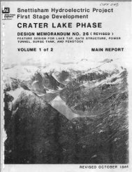
SUMMARY .L;PG N 93773. 3 SH~~T 1 OF 'i IH 0 L E Nu. DH - 1 13 E 86699.5 --- SURFACE ~L~V. 1409.4 1PROJ£C r Crater Lake DRILL DATES' START 6 Oct. 82 COMPo 14 Oct. 82DEPTH OF HOLE 392.2Of:PTH aF CJIIER8URO€N 2.0 DIA ... OF HOLE NXROCK ORILLED 390.2 CORE RECOVERED 310 ~ . 5 ~ RECOVERY 99.3 JAN('LE PROM VERT. 3C ot---- - ..AZIMUTH FROM NORTHDISTANCES: VEJn'1CAL. 119 - ~ HORIZONTAL. 196. :I .~..COMPtI;ED BY.DAT!,~tir ;' Jut 63ELEV Of~' LOGD€SCfltl~TION OF IIMT!IUALSCOMfIt!"AfltK!,1409.4 .._.! I -·-----t~O~VE~R~S~~~'R~D~E~~J~:~Il~lu~S~k~e~Q--------------~r----+b-.~o/---------------------i,I 407.7' ~-=::::-=:~QUARTZ DIORITE GNEISS: med. gray. ~RQD ~9II-~bdnded med .. gra i ned. nard. 1 i ght 1 y~weathered. liqhtly fractured. ~I\ ~CL ~Fractures qemi!rally clean and rough;i ~occ. lron stalns and pjrlte on JOlnt .~ ~ 51 i,,"osid,, em: w .he"ed bce"i~. L \.Joint ';;:;,1C1~1~ '_ 1 "'1'I vanes tr-Oil:-::';~\./I ~.loderately to highly fractured 2.0'- i, • IU.OI• - -4 3' I' ~ ~ --:- , : - . .I =c /'\,'.i,-- ~/-"1~• :'! !-\ ;I,'" /,,'i-~- ,'.'/~.,~I-~l:.._._\...~~ ... ~,~·;v~.Ij-1..--', " _.... !-~-,~/"".. \-/'- \ \', ~ I'" ,1 ---,\': l' -':-1, ., ..... ! \.!: ~ • I: 60_~Mi glTly fractured 59.0-59.2-\1':.. / •- -,- ~.,,~.::.' '--- , ' -'! -, -'-";oint spaClllg ~4.2~~~L'_ v a r i e 5 f r- 01'1 J. ~ '- o~ ".'; .), ~ .i .. = IiI ~QD 9CI-~ ~(II.'highly fracturedP~CJECT -_rj~.er --'~~,~.: 1 HOLE NO.----------.----~---~~~~--------------------.------------~.~~=-~~~~~--
SUMMARY LOG3773 3HOLE N DH-1l3 H6699.5PROJECT r Lake ORIl.L OATES' START0EP'1'H oF_HOL---=-=:....:E=--__ -+-OI:;;....;;.;.PTK-..:........;aF;..;.....-CW!R~_8U~R....;OE;..;;:....N___..j..:O=-IA-..-.-O¥~H-O~L;;.;.;E=---~ROC~ __ OR--'LL_E~ ___--+-=C-=OR..:...:..:=.E_R;...£=_C;:..O;:..V.;..;£~R~E::.;:O~______+_~..:......:·R~E=-C;;.;O:;..:V;..:E~R:....:.Y ___----__________ L-__________________________AMbLE FROM VERT. AZIMUTH f'ROfII NORTH-4COIIIPtUO BY. DAT!OtSTAHC!:S: VEJmCAl....... ZONTAL[LEV. MPTM LOG1322.1322. '00I ,, ~20 --~t:. \7.:/ t , ........ 1i .~I ~3u_ .,\.... ~U295.6. ~I ~r91.~ .~, ~40_~~I ~ ...1'284.91Ii~/'1D£SCIt'~T'O"0' IlATEIUALSStron~ oxidation and iron stains100.4-102.4'Yellow-brown clay gouge 105.0~i05 4'and iron stainin~HEARzor.E :. mod. to highly fractur~d100.4~l43.3; gray calcareou~ goug~common. Fragmented-, mod. soft I120~i.21.6'"tronq oXldation ·.'Ilth O.O~'silici ..fied~uuge ~26.6'
SUMMARY ,,,,00N 93773. 3 SM~~T 30F
PROJECT93 73.386699.5DRILL DATES' STARTDEPTH OF_HOL:....:-=-:::.:::E:.-__ -+D!:....;:.;..PTH~....;(JF;..;..._.;CWER;.......;;;;;..8U~R....;o€~N___ ~D=-'A=-.. -.~OF:....:........HO-:..:L;;.;:E=----ROCK DRILLED CORE RECOVERED ... RECOVERY==~----------~~~--~~~~~-----------4----~~~----------ANGLE FROM VERT. AZIMUTH FROM NORTH ~UD ." DAT!OtST AHCE S' VERT1CAL. HOIttZoefTAL~~~~~~r-____________________ D£SC"IPTION OF 1M1t"'ALS ~~C_a.~ .. ________________ RtMARKS __ jlUARTZ OIORITE GNEISSj ,RQD 100; 295.1'-335.2' ,JOirt sp~cing vari7s fro~:.2-19.0; avg. 5.633Q,Ij!RQD 96fractured 343.0~345.3'i, IHealed shear 348.9-349.5. highlyfracturedRQD 9lfractured 363.0~365,4'45 0 joint with ~inorchlorite 355.2'~L)D 95,'1 i til !' 1;11concentratiol! dtRQD 9-1071.aooN PA F 0'''' 7fT t,APR. 66 .,.:..:..j.---~=~~---::.,...."...- -------BOTTOM OF HOLEPROJECT-~ - . ------- - -I HOLE NO. ~"- __ .l., .
~~UMMARY 1'o~GI PAO::C~ ("tee ",.N 93773.3 1 SM~~T Ii Of 5 1\ OLE N . DH - ~ 11 E 86699.5 -r SURFAC£ ~LEV. 1409.4 !DRILl. DATES I START 6 Oct. 82 COMPo 14 Oct. 82 I~_~ HOLE 392.2' D€PTH 01 CW£RBUROEN 2 ..0 NXPO~K QRILLEO 390.2' CORE RECOVERED 387.5' .... RECOVERY 99.3 jI~_'-:E _r-~OM VERT. 30 0 AZIMUTH FROM NORTHO'S·T AMC.E S' VERTICAl.. ~ HORtZONTAL.I: ......E LEVOf.:P'noI I I OG D£SCRIPTION Of IMT£RIALSi : 1-..jI,;;-lOepth of Hole~hickness of Overburden~oCk Cor-eQ.Core Recovered1% Recovered392.2'2. a'390.2'387 . 5'99.3...ICOR£,DIAM. OF HOLEI330 0 COII1PIUD 8Y, DAn IIRUIARKS)~!j;.iIrrom20'! 90':90'. 29[/Pressure TestsTo90'90'90'92. ='-lj---.;1I HOLE NO. _.r -::~
SUMMARY LOGHOLE NPROJECT93731.0DRIU. DATtS I STARTD€P'TH OF HOLE 9 D!PTH OF O'IIRBURO€N 0 .0ROCK DRILLED 2 . 1 CORE RECOVERED 591.8I AN('LE FROM VERT. a AZIMUTH FROM NORTH 0DtSTANCES: VERT1CA&.oD€SC'U~T'OIIt. .... IZONTALOf fIIATlltlALSQUARTZ DIORITE GNEISS; med. gray,~-:';~banded,med. grained, hard, lightlyweathered, lightly fractured.Fractures generall~ clean and rough;occ. iron srains and pyrite onjoints; slickensides rare; occ.healed breccia.'ItCOM, ,to light1y traetured 0.0 9.5OIAM. OF HOl.ENX'RECOVERY 99.9COMPILlD 8Y. OAT!RQD 88RQD 95~T 11-4-82R(MARKS,..:1 ,RQD 86RQD 9-RQD 9560I ,0.01 clay gouge ~ 63.21;:00 29RQD 90-..QD 9612-10.NPA For ... ,19 t'APR.66 \,". Thin- calcite seam Cd !;fl.p'PROJECTenter LakeHOLE NO. jc;< ~4.':
ISUMMARY LOGHOLE N . DH-1l4PROJECT Crater Lake93731. 086934.0DRILL OATES I START0fP'TH OF_HOL...;....;;;...E~ __-+-_OI;;;...PTKOI~OVER8U_~_ .. _OE_- ..;,..."___-+Ot.::.-A_M_. OF.::.-_HOL...;....;...!.;;,......,._~ROCK DR~ILL==E~O _____ ~~C~OR~E~R~£~C~O..;...V~£..;...RE~D~ ______ ~_~~R~E~C~OV..;...E~R~Y~ __ __AH~~E .fROM_V_E_R_T_.__....I..-AZ_I.._UT_H_fRO __.._N_ORT __ H ___ ~ COIIIPtL[D BY...DISTANCES: VERT1CAL . HORIZ.ONTALCOMRtMARKSRQD 1001-11 ,-~-j!RQD 98IR0D :00: ::9.~-:~O.9~oipt sp~cing vari~s froG0.4- 7.2; avg. 2.3Minor red-brown ~l~y.~ougeslickensides at 15 •. 1withLost DWRat :5l.1Regain 90~ DWR @ :53I,9
PROJECT93731. 0B6934.0DRILL DATES' STARTDEPTH OF~HOL=E~ __--i...;;0€..;;;.....PTH_..;.OF.;,...-;;0YER....;...,;;;.8~U~R.;..;0E;.;;;...N ___ +D:..I.;.,;A.-;".;..' OF.:..:.-.;.,;H..:.OL~E~_~ROCK DRILLED CORE RECOVERED , RECOVERYANGLE FROM VERT. AZIMUTH FROM NORTH cow.UD BY. DAT!OIST AHCES: VERTICAL ....'ZONTAL- ..CQlltlII III. I ,I1100. S, ,Shear zone 216.8-227.3. highlyweathered. mod. fractured. hydrothermalalt. co~on.,graY,clay Igouge common 217-221. 0.5 gray cl~ymylonite 221~227.3',Slickensides ~ 228.0fractured 235.5~Z39.4'IRQO 93ROD 93RQD 9750 0 joint: biotite.greasy @ 264 ,40 0 joint; biotic~.flacky greasyat 267'ROD, ,:00; Z50.4-4~~.'';oint spacinc varies frorr:.0.3'-31. ;'; avg. ~ .0'Trace calcite and chlor~lte'''~S6'1037 ..... , .. 7metlAft .. ,,,.Crater Lake-..,~HOLE NO. DH'::J· ~
93731.086934.0PROJ E C TORILL DATES I START--~~~~~--~-----------------,--------------~OfPTH aF 0YER8UROfNOIAM. OF HOLELPO~KQRI'::l-E~ CORE RECOVERED ~ RECOVERY! AN\,LE n~~ VERT. AZIMUTH FROM NORTH ~UD BY. DAn----------~------------------------~. HORIZONTAL...D€SCAIPTIOfil 0' MATtRIALS RtMARKSCORtDIORITE GNEISSTrace of calcite,andchlorite @ 306.41,1..~Trace of calcite andchlorite @ 317'Trace of calcite andchlorite 0 33:.5'Chlorite :9 335',RQD 100; 250.4-4l~ -47.5'flcidic lone59.6'I ,olid core 355./-3S~.:,_NPA eIY"',~APR b6 . "" PROJECT '~rater Lake NO. JH
SUMMARY LOG7 1. 0HOLE N. DH-1l486934.0PROJECT Crater Lake DRILL DATES I START~ OF' HOL£ OE:PTH OF OY£R8UROEM DIAM. OF HOLEROCk DRILLED CORE RECOVERED % RECOVERYAH",Lf ___ _;ROM _ ________ VERT. -L-___________ AZIMUTH FROM NORTH --\ COtIIPtLlD 8Y. OAT'[DISTANCES: VERTICAl.. HQRJZOtIITALREMARKS-;1 ,.~00 97..Jidely spaced joints /limtraces of calcite andchloriteOcc. smooth joints in higFibiotite concentrationsSolid core 432.4-455.2, ,ROD 100; 421.7-451.7Joint spacing varies fro~0.4~22.8~ avg. 4.3'IIRQD 98I ,ROD :00; 46i.:-SZ:.SJoint spacing varies fr~'O.4~:2.:~ avg. i.9'B64. J .PROJECT Crater La~~' -", .' ~...... '...., -- _ ...I HOLE NO.••
SUMMARY LOG 93731.0HOLE N . 86934.0PROJECTDRILL DATES- START~------------~~~~~~--~----------------------~~----------------~, DEPTH OF HOLE O€PTH aF OVERBURDEN OIAM. OF HOLEr RO~~ DRILLED CORE RECOVERED ~ RECOVERYr----~,-LE n~o VERT, I AZIMUTH FROM NORTH ~UD 8Y. OAT!~ __ - ._ --------...L.-_______________-l. HORIZONTALR(MARtc.S,Joints have traces of 1calcite and chlorite; occ.;miCJS~'j~':OG,_ ~ll:: '..~ - . -PRCJECT:(,)t··r _:J'e- .--- --------------.--------j HOLE NO.--i..., J
~UMMARY LOG N 93731,0 1 SH.Efi 7 OF 7OLE NO. DH-1l4 E 86934.0 [SURFA~ ELEV. 1297.PROJECT Crater LakeDRILL DATES I START 6 Oct. 82 COMPo i.7 Oct. 82,DEPTH Of' HOLE 'i9,..1' O€PTH (:I OVERBURDEN· 0.0 DIAM. OF HOLE NX'-- ,,ROCK DRILLED 592.1 COR£ R£COV£R£D 591.8 ... RECOVERY 99.9-- --JANG.LE r~OM VERT. 30° AZIMUTH FROM NORTH 315 0 CO""'(D BY. OAT! I~---IDISTANCES' VERTICAL. 512 .8' ~ HORIZONTAL. 296.1'\I!EUV.iIDUTM ~LO.I.1...-1,,-.-..0'.. ,D€SCltI'TtOtII 0' IIMT!RIAl.SDepth of holeThickness of overburdenRock coredCore recovereO% Core recovered,IIFrom6'~ 1 6'~36'2 ~6', 240'Pressure TestsTo116'd6'2 :6'236'592.10.0,592.1,591.399.9592.2 , ,I!,if: (Ft .It-1in. ;19.66xlO~~ ,.~.46x~0_5"1.9 X10_ 5~.65xi.00.0...COMREMARKS'11~i"-',..1..--~1PROJECTCrater Lake,iIIl HOLE NO.-....i
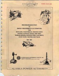
SUMMARY I~OGN 95300.4SHEET 1 Of 7 jHOLE Nu.DH-115E 91992 3 SURFACE ELEV. 803.9 IPR.OJEcr C:r.atel" ld~e ORILL DATES' START 9 Sept. 82 COMPo 28 Sept. st~~~~~~~~----~--------~~~~----~~~~~TH "-F ___ HOL-=-=E=--.\L.oh; ,,~;,o.......',,-/_+-~=PTH....:..:..__ aF.:..:......::0YER..:...=;.:.:8=.;U:..:.R..:.:0E:..=..N ___.:..3:..::.4~' ----Jf-=Ot;.:.:· A~M=.:....:OF=..:.....-:..:.HO=-L=E=--....:.N.:.::X_Jf-P
SUMMARY LOG 95300.4~OF_HOL~~E~ ____-+OE~~POCK DRILLEDCORE RECOV£REDAN\:"LE rROM VERT. AZIMUTH fROM NORTH-----DISTANCES: VEJImCAl. . HOaIZONTALShear zone: 100.6~102.6; fat, sofred-brown clay qouge 100.6~100.9'and 101.6~101.8; thermal alt.101.t~102.6; highly frac .• mod.weathered.Highly fractured :04.2~l06.7'some iron stainingQUARTZ DIORITE GNEISS: idem.; 120I --I;709.8IHOLE N . 91992.3PROJECTDRILL DATES· START__ ~OF~~~~8U~R_OE~N ______ ~ DIAM. __ ~ OF __ HOLE ~~ __ __... RECOVERY-" - --j----+--"-...;;;..............;;;..;;...=--~.;;;..;;;..------t__-::....;;...;........;.......----COWtLlD BY. DATERQD 82REMARKS~oint spacinq ~06. --~33.~from G.t-~ .~: avg.RQo 25RQD 98~ ~RQo 88IIjI1~-~iModerately to highly fracturedi33.1'-166.3'; pyrite common;joints;clean and mOderately rough.,yellow-brown CQdting 157.6RQo 90RQD 85I686.3,, II I ~ 7(L,i ~ ROD 9CIModerately fractured :66.3-i96.1RQU 996£2".5PROJECT:ratet' ~JkeRQo iOOI ~I HOLE NO. JH-::5 ..
! SUMMARY.",OG N 95300.4 SH£~T1 Of?I HOLE Nu. OH-llS E 91992.3 ISURFACE ELEV. 803.9PROJ.£CT . rr~tp)" 1 akl> .ORIU.. DATES· STAaT COMPo-+..=.O£=PTH---=...;..;.,..OF~OYER.;;:..:....::::...::..=B..::.U.:....:..RO£==.:.N-=--__-+=-DI~A="~. OF=---..:...:H-=.O=LE=--__ lI OO'~ ,QF .~HO.::..L=E=--__I ROCK OPILLEO CORE RECOVERED % RECOVERY j~.-- - ---------~~~~~~~~----------~~~~~~------_~ __ LE ~RON __ V_[_R_T_. __ l--AZ_IlllU __ T_H_F'ROM ___ NORT __ H ___--4COWtUO BY. DAT( IOl5T .'NCE S: VERTICAl.. ~ HORIZONTAL.... IR[MARKSC~[662 5' ~II~~~------------------------------~--~~~~~---------------ELEV :~~~Gec:1 DESCRIPTION OF fllATEI'IALSI1 ., 200 1~:\',' QUARTZ DIORITE GNEISS: idem.I " -I'I~,l'\;j --./..!?...... I I II ~-~:~ ,--'oderately fractured 206.1-208.6:'0 ~~._.. :;:-, ~..... I,/, ~,.I'.,,~ I I.- \_ ighly fractured 214.6-2:5.6~':!'7'f~-,~220 ~~'-.. -, '.. ,,17)1I ,,1_\' " '_RQD 100-RlJD 96I! ..i..I .! ~c10u 94!-I 7.oliJ cort: ~>L3-~3v,vj11j/ ,-~0CI ~OO: =22.6-292.6, ,Solid core 2:~.4-2;:i;.2:o1ia core '), I -Z.~-;:::S
SUMMARY LOG95300.4HOLE N DH-1l591992.3PROJECT enter La~e DRILL OATIS I START~_OF_.~HOL~:..::E ___-+Of~PTH....;..;,..:..-:;(JF;.;......;OVER~;..;.8U;;:;"":,,.:,R..;,.:OE:...;;;;,,;..;N___ +D:.:.IA:..:.":.:.:..:....:Of:..:...-H:..:..O::..:L::.:E:........-__P'OC~_AH~LEOR~LL ___E~ ________ ~C~OR~E~R~E~C~O;..;.V~E_R~ED~ ______ ~~'~R~E~C~O~V~E;..;.RY~ _____AZIMUTH FROM NORTH COWtLEO 8Y.FROM VERT.DISTANCES: VEJmC:AL. ... fZONTALM5Ci.UPTION Of IMTEft.ALS1Shear zone; 301.4-303.6, sandIgray-green gOU9€ @30l.8 ,0.01thick) mod. ~eathered 30l.~-302.hydrothermal alt. and calcitecommon,highly fracturedIQUARTZ 0 lOR I TE Gr~El SS: idem.IIII\REMARKSi-jRQD 90.Solid core, "3C3.6-2~:.:::-RQD~OO564 .. 2,~oderately fractured 33:.0-339.4BASALT: same as page 1. lightlyfractured "gray clay gouge 343.~-343.3RQD 99QUARTZ DIORITE GNEISS: idem.RQD 98ROD :00• . -, 1 CJOlnt spaClnc,I,-. "~~_.--~~~.~vanes fl'ol;IC:~/-:.9': J';:;'~2.0'RQD 99RQD 97, ,-JSolid core 394.4-4J5.J.......PRO.JECTIi HOL E NO. _'r, -. -::
SUMMARY LOG- N QC;1nn. 4HOLE NO. DH-il5 E 91992.3PROJECT CraterLake DRU DATES I START0€P'n4 OF HOLE.---- ---- .-,iII !Ii!IIII!IfIOfPTH C6 CWERBURO€N~OCK--DRILLED---..CORE RECOVEREDAHCLE rROM VERT..-AZIMUTH P'RO" NORTHD~T.,"C£S: V~CAL~ i HOItIZOIIITAL.I __~'110(PfM! L 06. , i,4.00 -4\I/\jI'4~Jl..]~ 'd,,_1 1 -I-: '··I..! 71/'11\-\;-/ IIj' n-I... -~-,,' ...."\ : 'I,{- I ~ I I. /1~ I , 1--- - II" IJ I\~ J ,.~ 'I 1• I-... i I'. 42Q I I ~,I, -" I ~J :1-\, _'~--~ I)I :-,~ ~-/Y_I.I,,,, 'Dl!Cl'I'TION OFIMTe.IALSQUARTZ DIORITE GNEfSS: idem.'II.COMIII!IiiIISW~~T 50f 7 1SURFACE ELEV. 803.9COMPoDIA ... OF HOLE~ RECOVERYCOMPtUD 8'1.ReMARKSDA~Solid core 394.4~435.0'I --I /,hOD lOO; 392.6-432.6/2 natural/breaks ~ 394.~and 394.4i ,I ,I....J_.I-1jI ,,1l1,~oderately to highly fractured435.cf-441.:'. Thin calcareous clay'coating on joint at 435.0' Gcc.pyrite and pale red-brown calcitecoatings on joints..: ~~:; ;;\::, :;;: '.'i"", ~"rf aCe flu", raL 3~ ~ ;;..~ '[(I~~ :;0I ' /iSolid core 44~.:-4S6.EiI, ,:'3=.5-46~.3I';'6:.~-':j.eI ,4c5.~-~9(,.,--,,492.i-522.;-;- •MPA Fo,,,, 7~ ,APR S'S "',PR.CJECTi HOLE NO . ..>'-,- __ =
______________________PROJECT____ ~£w~~~~95300.491992.3DRILl. DATU- START~--------------~~_O_F_HOL_E~ __-+..:;:..OI:::;;I'TM......:....:...:...-(J1;;.;;.....CMR..:;,..;".;:;..;..;.::I4..:;:..UI~"o€=N ___-!-=-D':...-A;.;..M;.;..' Of~..:....HO..:;:..L.=..E=--__ROCK OR~ILL~E~D ______-+~C~OR_E~~_E~C~O~V~E~~~E~D~_____-+'__ R;.;..E~C~O~V~E~R_Y ______~LE FROM VERT. AZIMUTH PROM NORTH COWtLlO BY. DATtOtST ANeE S; VElmCAL. HORIZONTALMSCI'IPTIOM OF IMT(RIALS c:' R(MARKS~~~~~~~~------------------------------~---*-----------------------.;DIORITE GNEISS: idem. Solid core 503.3~516.2' 1i1II ,!f29.1. II~' ....52(L ~ZS~l,I I _l "~I' I I'" -,,-.' '7-... ' I f..iighly fractured 525.0-526.3· ""-' \ I-'I'!~! !530_ ~n!-Shear zone 530.0~532.6~ nod. to ,:11hiohll frac. 530-533.4'and 536.4-:.' ' 53iLQ:; fragmented wlth occ. c71c-· _ areou;; gray-green gouge 533.4-~23. 1 ~~ 536.4: red-brown calclte coatlng'54~}~~~~,common on JOInts.~\I ~/ ......-
SUMMARY I~OG N Q'i1nO.4 SH£~T 7 OF 7 :I H 0 L E Nu. DH-115 E 91992.3 SURFACE ~l.~V. 803.9 1! PROJECT . r .. ~tpr I ;kp DRILL OATES- START 9 ~PfltR? COMP'?R
APPENDIX BHYDRAULIC DESIGNBlB2B3B4HYDRAULIC DESIGN OF RECOMMENDED PLANSUPPORTING TECHNICAL DATA FOR HYDRAULIC DESIGNOF RECOMMENDED PLANHYDRAULIC DESIGN OF ALTERNATIVE PLANS I ANDHYDRAULIC DESIGN OF ALTERNATIVE PLANIIIII
APPENDIX BlHYDRAULIC DESIGN OF RECOMMENDED PLANB1-1
TABLE OF CONTENTSAPPENDIX BlHYDRAULIC DESIGN OF RECOMMENDED PLANPARAGRAPH1 .01 GENERAL1.02 DESCRIPTION OF THE POWER CONDUITA. GeneralB. AlinementC. Power TunnelD. PenstockE. Rock Traps(1) Primary Rock Trap(2) Secondary Rock Trap(3) Final Rock TrapF. Trashrack Design(1) Primary Trashrack(2) Secondary TrashrackG. Gate Structure TransitionH. Gate Structure Service Gate(1) Gate Closure(2) Gate OpeningI. Tailrace and Forebay Water Surface Elevations(1) Tailrace Elevations(2) Forebay Water Surface ElevationsJ. Machine Bored Tunnel (MBT)1.03 HYDRAULIC LOSSESA. GeneralB. Losses in the Power Conduit(1) Unlined Tunnel(2) Concrete Lined Tunnel(3) Steel Penstock(4) Rouse Rough Pipe Limit Versus von Karman-PrandtlFully Rough Equation(5) Minor Losses in the Power ConduitPAGEBl-2Bl-4Bl-4Bl-4Bl-5Bl-5Bl-5Bl-5Bl-5Bl-6Bl-8Bl-8Bl-8Bl-9Bl-l0Bl-l0Bl-10Bl-11Bl-1181-13Bl-13Bl-14Bl-14Bl-15Bl-15Bl-17Bl-19Bl-19Bl-21i
PARAGRAPHC. Hydraulic Losses in Machine Bored Tunnel (MBT)D. Refilling of Tunnel TurnoutsE. Hydraulic Losses from Drafj Tube to Tailrace(1) Condition with 518 ft I~(2) Condition with 1,640 ft Is(3) Assumptions1.04 HYDRAULIC TRANSIENTSA. Operating RequirementsB. Need for a Surge TankC. Net Turbine Heads Used for-Design(1) Maximum Net Head(2) Design Net Head(3) Critical or Minimum Net Head(4) Rated Net HeadD. Turbine SizingE. Surge Tank LocationF. Surge Tank Diameter(1) The Thoma Formula(2) Expected Tunnel Size(3) Diameter Selection(4) Computer VerificationG. Machine Bored TunnelPAGEBl-22Bl-22Bl-23Bl-23Bl-23Bl-23Bl-24Bl-24Bl-24Bl-24Bl-25Bl-25Bl-25Bl-25Bl-25Bl-27Bl-28Bl-28Bl-28Bl-29Bl-2981-29H. Long Lake Turbine Model and Prototype Turbine Characteristics 81-29(1) Turbine Model Bl-29(2) Prototype Turbine Characteristics 81-30(3) Wicket Gate Closing Rate Bl-30I. Computer Models(1) Computer Program "WHAMO"(2) Computer Program "MSURGE"J. Stabil ity by "WHAMO"(1) Results of "WHAMO" Runs(2) Governing StabilityK. Transient Analysis(1) Load Rejection(2) Load Demand(3) Emergency Closure of Spherical Valve(4) Hydraulic Loads on the Penstock Thrust BlockMachine Shop BulkheadandBl-31Bl-31Bl-31Bl-31Bl-31Bl-32Bl-34Bl-34Bl-34Bl-35Bl-36i ;
PARAGRAPHL. Speed Regulation and Hydraulic Capacity(1) Speed Regulation(2) Hydraulic CapacityM. Transient Background and SummaryN. Crater Lake Phase Without a Surge TankO. Hydraulic Losses Used in Hydraulic Transient Study(1) Horseshoe Tunnel(2) Machine Bored Tunnel1.05 LAKE TAPA. GeneralB. Orifi ceC. TrashrackD. Primary Rock Trap( 1) Genera 1(2) Containment of Blast Rubble(3) Tractive Forces in Rock TrapE. Fi na 1 Lake Tap Bl astF. Final Lake Tap LocationPAGEBl-37Bl-37Bl-37Bl-38Bl-39Bl-40Bl-40Bl-40Bl-41Bl-41Bl-41Bl-42Bl-43Bl-43Bl-43Bl-44Bl-44Bl-48iii
APPENDIX B1HYDRAULIC DESIGN OF RECOMMENDED PLANB1-1
APPENDIX BlHYDRAULIC DESIGN OF RECOMMENDED PLAN1.01 GENERALAppendix B describes the hydraul ic design of the power tunnel, surgetank, and penstock for the .Crater Lake phase of the Snettisham powerfacilities. The surge tank design requires consideration of the plantoperating conditions, expected turbine characteristics and the total headlosses in the conduit system from the reservoir to the powerhouse. Thepower conduit will be connected to a turbine-generator unit which is to beinstalled in the existing powerhouse which was built for the Long Lakephase of the Snettisham project.Computation sheets for selected aspects of the surge tank design, waterhammer, and conduit hydraul ic losses are included in Hydraul ic AppendixB2. Computer printouts from the digital computer programs used forhydraulic transients are also presented in appendix B2. Hydraulic AppendixB3 describes alternative plans I and II. Alternative II is the onerecommended in OM 23, which was the GDM for the Crater Lake phase datedDecember 1973. Alternative I differs from alternative II only in the typeof gate shaft that is used. Both a lternat ives use a vented surge tank.Hydraulic appendix B4 describes alternative III which incorporates the airchamber surge tank.Two consultants were retained to assist the District in the hydraul icdesign of the project. Polarconsult, Inc., of Anchorage, subcontractedIngenior CHR. F. Gr¢ner of Oslo, Norway, who advised us on the lake tap,rock traps, and general tunnel design. Dr. Hanif Chaudhry of Wa.sh·ingtonState University (formerly of Old Dominion University) advised us onAlternate Plan III which incudes hydraulic transients in the air chambersurge tank plus water hammer and speed rise at the turbine. The Reportsubmitted by Polarconsult is included in Volume 1 of this report as Exhibit4. The report submitted by Dr. Chaudhry is exhibit Bl in Appendix B4.Bl-2
Various plates which appear in both volumes of this report are referredto in this appendix. Plates identified by a number only are located inVolume 1 and those identified by a letter and number (Bl through B27) arelocated at the end of the Hydraulic Appendix. The exhibits referred to arein Volume 1 of this report. References are located at the end of appendixB1.Bl-3
1.02 DESCRIPTION OF THE POWER CONDUITA. General. This subsection describes the various portions of thepower conduit in sequence, beginning at the lake tap entrance andcontinuing onto the powerhouse. The power conduit plan and profile areshown on plates 2 and 3.B. Alinement. The center of the lake tap opening is located atapproximate sta 7+52, at approximate elevation 799, with the trashracklocated 4.0 ft above the opening. The invert of the primary rock trapvaries from elevation 753.5 to elevation 766.2. The minimum power pool isset at e 1 evat i on 820 to assure adequate clearance over the top of thetrash rack and or ifi ce. The rock trap trans it ions to an ll-ft diametermodified horseshoe tunnel at sta 8+50 which moves upgrade to the gatestructure which is at approximate sta 14+00. The 4 percent upgrade slopefrom the primary rock trap to the gate shaft is intended to facilitate theescape of air during the initial tunnel-filling operation, and to a lesserextent, following the blast. A downward slope from the end of the rocktrap to the gate shaft would create a peak at the end of the rock trapcapable of trapping air and is therefore avoided. A secondary rock trap islocated upstream from the gate structure between sta 11+40 and sta 12+00.Th i s rock trap wi 11 intercept any mater i a 1 s swept out of the 1 ake tap areabefore they can reach the gate structure. At the downstream end of thegate structure the tunnel is set on a constant 12.437 pct grade to thesurge tank drift tunnel at sta 65+59 and the final rock trap locatedbetween sta 67+50 and sta 68+50. The final rock trap transitions to thestart of the 6-ft diameter steel penstock at sta 68+75 which continues onto the powerhouse at sta 78+29. The total length of the power conduit isapproximately 7,000 ft with the length of the penstock at 925 ft (includingtransitions), the power tunnel length at approximately 6,020 ft, and thelength of the spiral case extension at 65 ft. After exiting from thepowerhouse the discharge enters the tailrace where a special IIconstantlevel llgate currently keeps water surface elevations between 11.0 ft and12.5 ft.Bl-4
C. Power Tunnel. The power tunnel is an ll-ft mod ifi ed horseshoe withan overall length of approximately 6,020 ft. Tunnel lining will berequired in those sections where faults or poor rock conditions are found.Tunnel lining will consist of concrete or shotcrete depending uponcircumstances but in no case will the tunnel diameter (lined section) beless than B.O ft with the exception of the gate structure. Typicalsections and details of the tunnel are shown on plate 4.D. Penstock. The penstock is a 6-ft diameter steel structure with anoverall length of 925 ft including transitions. A typical section of thepenstock is shown on plate 5.E. Rock Traps.(1) Primary Rock Trap - The rock trap at the entrance to thetunnel is part of the lake tap and is discussed ;n paragraph 1.05 of thisapp'end;x.(2) Secondary Rock Trapa - The secondary rock trap ;s located between sta 11+40 and sta12+00 and ;s shown on plate 20. The rock trap will be an 11 ft high and 20ft wide straight sided horseshoe with an additional 2 ft excavated beneaththe tunnel invert for sediment storage. The rock trap crown will match thealinement of the power tunnel crown so as not to trap air at the crown ofthe rock trap during tunnel filling for the lake tap. This 20 ft widesection may also serve the additional function of providing a constructionturnout either as-is or by widening it slightly.b The storage are .. located in the bottom of the rock trap has anapproximate volume of 44 Yd 3 • The cross-sectional area of the trapvaries from 190 ft2 to 230 ft2 (depending on sediment accumulation)resulting in a maximum velocity ranging from 2.7 to 2.3 ft/s with themaximum expected discharge of 51B ft 3 /s.Bl-5
c Calculations based on references 19 and 24 indicate that thetrap will intercept any particle larger than approximately 1/8 in. Thesecondary trap is being built for the following reasons:To assure that any materials that might pass through the primaryrock trap are stopped before going towards the penstock.2 To assure that the gate slots (at approx imate sta 14+00) remainclean for efficient operation of the service gate and the bulkhead.d A CELSEP type trap had been considered at this location but withmaximum velocities in the unlined portion of the tunnel being only 5.04ftls it was concluded that a more conventional rock trap would be adequatefor the job.(3) Final Rock Trap -a Background. The final rock trap is built on a 12.44 pct slopewhich requires some modification from the original design recommended byPolarconsult. The sloping tunnel may, at first glance seem to create aphysical condition in which all the rock particles entering the trap areswept down to the foot of the trashrack at the downstream end of the rocktrap but this is not so.A slope of 12.44 pct is equivalent to an angle of7.1 degrees which is a very shallow slope when looked at in terms ofincreasing potential particle movement. For instance, for a material withan internal friction angle of 35 degrees, equation 34 on page 41 inEIVllllO-2-1601 shows that the design shear (the shear that a particle canresist at incipient movement) is reduced by only 2 pct when a particle isplaced on a 7.1 degree slope.The main factor in moving materials at a slope of 12.44 pct is thevelocity of flow. The Long Lake inspection tr"ip of 21-22 June 1983 showedthat only small quantities of materials have been moved down the tunnel.After various considerations it is anticipated that the quantities ofmaterials arriving at the final rock trap will be small because:Bl-6
The primary and secondary rock traps located at the upper end ofthe tunnel will intercept the great percentage of materials that will enterthe tunnel or that are present as a result of the final blast.2 The rock through wh i ch the Crater Lake tunne 1 will be bu i lt issimilar to that found in the Long Lake tunnel and is therefore sound. Onlysmall quantities of materials are expected to come from the tunnel walls.3 Any residual materials remaining from construction will beremoved before the final blast.(b) Description of the Trap. The final rock trap begins at sta67+50. The maximum velocity through the trap will be 2.58 ft/s based on across sectional area of 200.8 ft2 and a maximum discharge of518 ft 3 /s. Gradual trans i t ions 1 ead into and out of the trap to reduceturbulence to a minimum. The downstream end of the trap at sta 68+50contains the secondary trashrack.A concrete 1 i ned trans it i on between the trap and the penstock in theshape of a truncated cone is located just downstream from the trashrack.The transition begins as an ll-ft diameter circle and is reduced to a 6 ftdiameter circle in a 25 ft length. Details of the trap are shown on plate21.(c) Particle Movement In The Final Rock Trap. The transition intothe final rock trap begins at sta 66+90 with the full rock trap crosssectional areas of 200.8 ft2 being available at sta 67+50. Thetrans it i on wi 11 be excavated out of the roof of the tunne 1 to keep invertturbulence to a minimum. Calculations based on references 19 and 24 showthat particles ranging up to 1 3/16 inches will be moved down the tunneltoward the final rock trap when maximum velocities reach 5.04 ft/s. Uponreaching the main portion of the rock trap at sta 67+50, maximum velocitieswill be reduced to 2.58 ft/s which results in any particle small than 1/8inch remaining on the floor of the trap. As time progresses, the sediment ~,front will move downstream towards the trashrack (similiar to the movementBl-7
that occurs in a reservoir). An excavation at the downstream end of therock trap will prov i de approx imate ly 96 yd 3 of storage vo 1 ume for anymaterials that might reach that far. The trap will be cleaned whenever thepower conduit is drained for normal inspection and maintenance. HEDB hasindicated that the turbine can pass a 2 inch diameter stone once during itslife and can pass a 1/4 inch diameter particle on a more regular basis. Toassure a long turbine life the rock trap is designed so that a 1/16 inchdiameter particles entering the trap from the power tunnel will settle tothe floor of the trap well before reaching the lower trashrack (seereference 2, 3, and 4).F. Trashrack Design. For hydraulic design purposes, the same spacingas that used for the Long Lake trashracks was assumed for Crater Lake. Forthe primary trashrack the bar spacing is assumed at 2-1/2 inches center tocenter and 2 inches between bars. For the secondary trashrack justupstream from the penstock the spacing is assumed at 1-7/8 inches center tocenter and 1-3/4 inches between bars.(1) Primary Trashrack - The primary trashrack will be 19-ft squarewith maximum velocities of 2.1 ft/s through the net area. The primarytrashrack design is discussed in greater detai 1 in subsection 1.05 - "LakeTap" of this appendix.(2) Secondary Trashrack - Prior to the initial period of plantoperation a full circular trashrack 11 ft in diameter will be installedupstream from the penstock (see plate 21). The trashrack will providepositive protection for the turbine during the initial stages ofoperation. Inspection of the new tunnel after some period of partial andfull power operation will allow us to make a decision about whether or notany portion of the secondary trashrack can be dispensed with (the Long Laketunnel operates with a partial trashrack at this location).Bl-8
G. Gate Structure Transition.(1) Since the gate slots for the service gate and bulkhead at thegate structure must be formed in concrete, there must be a transition fromthe unlined rock tunnel to the concrete section and back to the unlinedrock tunnel.(2) An economic study was performed to determine the optimum gatesize and concrete transition length. Gate sizes studied were 4 ft x 9 ft,4 ft x 10 ft, 5 ft x 10 ft, 6 ft x 11 ft, and 7 ft x 12 ft. Transitionlengths (including both contraction and expansion) studied were 30 ft, 75ft and 225 ft. Construction cost for each of these alternatives wasdetermined and added to the value of the head lost due to friction for eachof the alternatives, to determine which combination would be the leastcost lyon an average annual cost bas is. The annual value of one foot ofhead used was $20,998 based on escalated fuel costs as calculated by the<strong>Alaska</strong> District. This value for one foot of head varies from the currentvaiues using escalated fuel costs due to continual adjustment of fuel costvalues, but this will not Significantly effect the gate structure economicanalysis. Head losses due to the concrete lining, gate slots, contractionand expansion were considered. An effective roughness (Ks) value of0.0016 was chosen for concrete based on HDC 224-1; K = .02 (losscoefficient) was chosen for the gate slots based on EM 1110-2-1602 and HDC228-4 was used for determining K values for the contraction. Brater andKings' Handbook of Hydraulics 6th Edition page 6-22 was used for determingf values for the expansior. since HDC 228-4 is vague for the flow situationsconsidered. K values for the contraction varied from 0.0 to 0.07 in theformula:and f values for the expansion varied from 0.034 to 0.40 in the formula:hL = f(V~- V~)2g81-9
Stud i es were done for discharges of 300 ft 3 /S and 395 ft 3 /s, bracket i ngthe average flow of 329 ft3/s • The studies showed that the smaller gatesizes with intermediate transition lengths were the most economical.However, it was decided that the minimum gate size must be 6 ft x 8 ft topermit passage of a small tractor for construction. Using the 5 ft x 10 ftgate as hydraulically similar to the 6 ft x 8 ft since it has about thesame flow area, it was found that for this gate opening size a 55 ft totaltransition length was the most economical. As a result of thesecalculations the 25 ft upstream and 30 ft downstream transitions werechosen. The 24 ft center section was chosen to provide an adequateinterface, hydraulically, between the contraction and the expansion.(3) Since filling of the tunnel will be accomplished with thetunnel filling pipe and valve, high velocity flows are not expected tooccur under the gate except ina rare emergency gate closure. Therefore,no special cavitation protection is included in the gate structuretransition design. Plate i5 shows details of the gate structure.H. Gate Structure Service Gate.( 1 ) Gate Closure. Once a gate size was selected based oneconomics and construction requirements, the major hydraulic design factorwas the selection of an appropriate gate closing time. Since in anemergency such as a penstock rupture or wicket gate failure the tunnel willrequire anywhere from 4 to 45 minutes to drain, it is not necessary torequire an overly rapid service gate closure. Also, a rapid closure willcause a surge up the gate shaft which will cause extensive flooding in thegate structure service room. Emergency service gate closure in the case ofa penstock rupture was simulated on WHAMO. Flow through the power conduitdue to a penstock break is about 3,650 ft 3 /s as calculated by WHAMO andverified manually. Computer runs were made for 60, 80, 90, and 120 secondstra i ght 1 i ne closure rates. Graph i ca 1 output for the 80 second and 90second gate closure rates appear in Hydraulic Appendix B2 as figures 1 and2, and the "WHAMO" input file for the 80 second closure appears as figure3. Both the 60 and 80 second closure rates resulted in a considerableBl-lO
quantity of water in the gate structure service room above elevation 1,040ft. The 90 second closure rate resulted in a maximum water surfaceelevation of 1,033 ft, which is 7 ft below the floor of the service room.Due to the possibility of personnel being in the service room and the lackof justification for a rapid service gate closure a 10 minute closure ratewas chosen for use in emergency situations. A more detailed analysis ofgate closure times based on further IIWHAMO II runs, manual calculations andconsultation with WES will be done for final analysis (plans andspecifications).(2) Gate Opening. The service gate is not to be opened underunbalanced hear, except in a rare occurence of tunnel filling through theservice gate in the event of a non-repairable tunnel filling pipe orvalve. In order to minimize the potential for operator error in theralSlng of the service gate under unbalanced head, a limit switch will beprovided to prevent opening of the gate more than 0.2 inches per eachoperator signal (for the first 2 inches of opening). A large gate openingunder unbalanced head could result in an initial surge of water and highvelocity flow through the tunnel which could damage the final trashrack,carry 1 arge stones through the tunnel and penstock, and resu lt in othermiscellaneous damage throughout the power conduit.I. Tailrace and Forebay Water Surface Elevations.(1) Tailrace Elevations -a. Plate 18 in Snettisham Design Memorandum 10 shows a chart oftail water elevations that ranges between -1.5 ft and 11.4 ft. In recentyears the State of <strong>Alaska</strong> has built a fish hatchery in the tailrace whichutilizes a portion of the powerhouse discharge. The tailwater elevationsnow range between 11.0 ft and 12.5 ft and are controlled by IIConstantLevel II gates built by Alsthom Atlantic Incorporated, Model number 0630.The gates rotate about a hori zonta 1 shaft and are actuated by the waterlevel on the upstream side. During a visit to the site in June 1982,tailwater elevation was observed to be 11.4 ft with an approximateBl-ll
discharge of 480 ft 3 /s. The hatchery personnel can change the tail watere 1 evat ions by varyi ng ballast wei ghts in the contro 1 gate with max imumallowable water surface elevation being 12.5 ft. At this elevation themaximum allowable discharge of 200 ft 3 /s is entering the hatcheryraceways. The control gates were designed to limit the tailwater elevationto 12.5 ft even during the maximum expected tide of 11.4 ft and with amaximum plant discharge of 1,680 ft 3 /s including discharge from the newunit.b. More recent ly, when the Department of Fi sh and Game becameaware of the annual charges the <strong>Alaska</strong> Power Administration would be makingdue to lost potent i a 1 energy caused by the increased ta il water, Fi sh andGame decided that the hatchery would be able to function with lowertai.lwater than previously anticipated. Ultimate tailwater elevations atthis time are uncertain, but it seems reasonable to assume that regardlessof what may happen in the future, the concrete structure that houses the"Amil Automatic Gates" presently controlling tailwater elevations willremain, and will act as a broadcrested weir with a sill elevation of 1.7 ft.c. Tailwater Curve. Figure 4 shows the tailwater curve that willbe used to obtain the minimum water surface elevations. The broadcrestedweir equation: Q = (C)(B)(H)3/2 was used where:Q = Total discharge across the weir (ft 3 /s).B = The total length of the weir (ft).H = <strong>Energy</strong> available just upstream from the weir (ft).C = Weir coefficient.The total length of weir is 24 ft, and the weir coefficient is assumed at3.50 which is somewhat on the high side, but it does produce minimumtailwater, which, for our purposes is a conservative approach becauseturbine submergence was our primary concern. Maximum tailwater elevationBl-12
will be approximately 12.5 ft and occurs only when the maximum plantdischarge of 1,640 ft 3 /s is concurrent with the maximum expected tidalelevation of 11.4 ft.(2) Crater Lake Surface Elevations - The average recorded outflowbased on hydrologic records for Crater Lake is 193 ft 3 /s which representsa lake elevation of approximately 1,018.6 ft.For the sake of beingconservative a lake surface elevation of 1,022 ft was selected fortransient and pressure calculations. The natural outflow at elevation1,022 'is approximately 800 ft 3 /s.J. Machine Bored Tunnel (t"IBT). A MBT wi 11 be accepted as an optionfor the Crater Lake Project. A MBT of ll-ft diameter would be acceptablein lieu of an 11-ft diameter modified horseshoe.losses a 11In terms of hydraulicft bored tunnel is comparab 1 e to the proposeo ll-ft horseshoe(see figure 5 of Hydraul ic appendix B2).Although the bored tunnel issmoother, the horseshoe tunnel wi 11 be 1 arger, due to the dri 11 and blasttechnique. The maximum velocity in a ll-ft diameter bored tunnel is5.5 ft/s wh i ch is acceptab 1 e in the rock to be encountered. Where rockconditions dictate lining requirements the tunnel diameter will be 9 ft forconcrete lining and a minimum of 9 ft for shotcrete lining.Because of thesmoother tunnel walls in the bored tunnel a 12 ft diameter surge tank isrequired to maintain stability in the system (see figure 6 of HydraulicAppendix B2). If the contractor chooses to bore a 1 arger tunnel, acorrespondingly larger surge tank would have to be built.Bl-13
1.03 HYDRAULIC LOSSES.A. General. Head losses in the power conduit are primarily caused byfrictional resistance to flow. Additional losses are caused bycontractions and expansions as flow moves into and out of rock traps~ linedsections and the gate structure. Further losses are caused by flow throughbends in the main rock trap~ the power tunnel and the penstock.In caJculating head loss~s each feature producing a hydraulic loss wasassigned a loss coefficient IIKII~ and a corresponding headloss wascalculated by the following equation:All losses were summed up, and for convenience a second form of theheadloss equation was related to the total discharge in the power conduit.This equation is:K = Loss coefficient for individual feature.hL = Head loss for individual feature (ft).V = Velocity at individual feature (ft/s).HL = Total head loss in power conduit (ft).Q = Total discharge through power conduit (ft 3 /s).K = Overall loss coefficient for entire conduit from intake to turbine.g = Acceleration due to gravity (32.2 ft/s2).The Manning formula was used to calculate friction losses in theunlined sections of tunnel while the Oarcy-Weisbach formula was used forthe 1 i ned port i on of the tunnel and the penstock. It was felt that theManning formula would be more appropriate for the irregular unlined tunnel.Bl-14
Figure 7 in appendix B2 contains a summary of hydraulic losses along withdetailed loss calculations.Calculations were performed for maximum, expected and minimum hydrauliclosses. Expected losses were used for determining the economic tunneldiameter. Maximum losses were used to calculate minimum internal pressuresincluding minimum water hammer at the unit. Minimum losses were used tocalculate maximum internal pressures, maximum water hammer and stability ofthe surge tank.For detailed breakdowns of all losses for the different sections of thepower conduit, see figure 7 in Appendix B2. Plate Bl illustrates hydrauliclosses in various portions of the power conduit.B. Losses in the Power Conduit.(1) Unlined Tunnela Expected Losses - The unlined portion of the power conduit is anll-ft modified horseshoe tunnel as shown on Plate 4. The effectiveroughness in the unlined tunnel is expected to be approximately 4-1/2inches or 0.375 ft. The nominal tunnel area is 102.8 ft2 which resultsin a circular equivalent diameter of 11.4 ft and a relative roughness (perHOC 224-1/6) of 11.4 ft/.375 ft = 30.5. Based on this relative roughnessthe Von Karman - Prandtl roughness Equation provides a Oarcy-Weisbachfriction coefficient IIfli of 0.0585 and a Manning lin II of 0.0267, butreference 5 shows that relative roughness alone cannot fully definehydraulic resistance in unlined tunnels. Scalloping or waviness resultingfrom drilling and blasting techniques are an important factor in hydraulicresistance. Therefore, Manning's lin II was based primarily on empiricalfindings at existing tunnels summarized in HOC chart 224-1/5. Afterconsideration of 12 tunnels ranging in design cross-sectional areas from 54ft2 to 183 ft2 (nominal tunnel cross-sectional area at Crater Lake is102.8 ft2) an initial value of lin II = 0.0315 was chosen for expectedBl-15
conditions. After going through a series of calculations to find themaximum and minimum losses as shown in the following paragraphs theexpected "n" value was rounded off to 0.031.b Maximum and Minimum Losses - With the expected value of "n" =0.0315, a Oarcy-Weisbach friction factor of 0.0186 was calculated by theequation:f = 185 n 2(Dm) 1/3(Ref 21, p. 6-15)where:f= Oarcy-Weisbach friction factorOm= Circular equivalent of horseshoe tunnel; in this case, 11.4 ft.n= Manning's "n"HOC chart 224-1/6 was then used to find the relative roughness (15.2 onthe x-axis) corresponding to a friction factor of 0.0186. The effectiveoverbreak, including effects of scalloping along with normal tunnelroughness was equal to 0.75 ft (11.4 ft/15.2 ft). To obtain maximum andminimum "f" values, "auxillary" curves parallel to the fully rough curvewere drawn on HOC chart 224-1/6 (see figure 7-38 in Appendix 82). These"auxillary curves represent approximate limits of maximum and minimum losscoefficients for the tunnels that were being consiaered. A vertical linewas drawn through the fully rough line at the expected relative roughnessof 15.2. The intersection of this vertical line with the two auxillarycurves resulted in maximum and minimum "f's" of 0.099 and 0.069respectively. Which were then converted to equivalent Manning's "n" of0.029 and 0.0347.c Sensitivity to Tunnel Size - It is the general experience intunnel construction that the average as-built tunnel diameter is largerthan the design or nominal diameter and this project will be no exception.If the completed tunnel has an average diameter of 12.2 ft with an81-16
accompaning cross-sectional areas of 126.5 ft 2 , -the expected lin II valuecould be as high as .041 without reducing the design head. If thecompleted tunnel has an average diameter of 11.5 ft with an accompanyingcross-sectional area of 112.3 ft 2 , the expected lin II value could be ashigh as .035 without reducing the design head. It is therefore concludedthat the selection of .031 for the expecting Manning loss coefficient is areasonably conservative assumption.d Required surge tank diameter is related to hydraulic losses andtunnel areas. Therefore, tunnel roughness and cross sections areas will bemeasured by photogrammetric methods as described in references 6, 7 ana 8and/or by physical measurements as the tunnel is being built. A discussionof the sensitivity of the surge tank diameter to minimum loss coefficientsis part of Section 1.04 - "HYDRAULIC TRANSIENTS. II(2) Concrete Lined Tunnel For the initial hydraulic losscalculations it was assumed that there would be approximately 800 ft of9-ft diameter lined tunnel. Tunnel lining was foreseen at Cliffside,Hilltop, Tlingit and Tsimshian Faults (see Plate 4). In addition, concretelining will also be required for the gate structure and its transitions.Expected friction losses are based on an assumed effective roughness (Ks)of .0016 ft which was the value measured for Enid Dam Project (HDC 224-1)and is considered a good average (conservative) value. For expectedlosses, an average discharge of 335 ft 3 /s was anticipated and was used toobtain a Reynold's Number. Once the Reynold's Number and the relativeroughness were known, the Darcy-Weisbach friction factor was obtained fromthe "Moody Diagram" (HDC chart 224-1).For maximum and minimum losses, a discharge of 500 ft 3 /s was assumedto obtain a Reynolds Number. This value of 500 ft 3 /s is only anapproximation of actual discharges and it is used only to obtain a ReynoldsNumber. The values of the Darcy-Weisbach friction factor are a function ofthe Reynolds Number but are not particularly sensitive to the ReynoldsNumber and therefore the assumption of a 500 ft 3 /s discharge isappropriate (the finalized maximum discharge is 518 ft 3 /s). MinimumBl-17
friction values were obtained from the Von Karman-Prandtl smooth pipe lineat the appropriate Reynolds Number (HOC chart 224-1) while the maximumfriction values were based on the Rouse rough pipe limit which in this casewere equal to or greater than the values obtained from the VonKarman-Prandtl fully rough equation.See paragraph 1.03 8(4) below for afurther discussion of the Rouse rough pipe limit versus Von Karman-Prandtlfor determ"ining maximum losses.for the concrete-lined section of the power tunnels.The following friction factors were usedCond it i onMaximum LossesExpected LossesMinimum LossesOarcy-Weisbach IIfll0.01600.01370.0093IVJanning "n"0.01340.01240.0102Friction values were taken directly from the IIMoodyll diagram with theVon Karmon-Prandtl Smooth Pipe Equation and the Rouse Equation being usedf.or an occasional check.As the design of the Crater Lake Project proceeded, foundationinvestigations provided more information on the rock conditions along theproposed tunnel alinement. As a result, we now anticipate that there willbe only 125 ft of concrete lining along with approximately 920 ft ofshotcrete 1 ining.Calculations were made comparing the hydraul ic lossesfor 800 ft of concrete-lined tunnel with the losses that would occur for acombined total of 1,045 ft of concrete and shotcrete lining. Thecalculations sowed that with an average discharge of 335 ft 3 /s, usingexpected losses, the total difference in head loss for the differentcondit ions was on ly 0.23 ft. The shotcrete-concrete comb i nat i on resu ltedin smaller losses than the concrete section. For the maximum discharge of518 ft 3 /s the head loss difference was 0.44 ft which represents only 2.2pct of the total losses from intake to surge tank.This was felt to beinsignificant and no changes were made in the orig"inal hydraulic losscalculations.81-18
(3) Losses in Steel Penstock - Friction losses in the 6-ftdiameter steel penstock were calculated in a fashion similar to that usedfor the concrete-lined portion of tunnel. An effective roughness of0.00005 ft was chosen for calculating expected losses. This roughnessvalue is one-half the recommended value for discharge computaticry inHDC-224-1/1, but is equal to observed prototype data in the samereference. The effective roughness value of 0.00005 ft assumes goodmaintenance of vinyl paint. The interior of the Long Lake penstock was inexce 11 ent shape when inspected in the summer of 1983 after 10 years ofoperat i on and s imil ar performance is expected for the Crater Lake penstock.To obtain appropriate Reynolds Numbers an expected average discharge of335 ft 3 /s was assumed for expected losses and a discharge of 500 ft 3 /swas assumed for maximum and minimum conditions. As in the lined tunnel,minimum and maximum friction values were obtained from the smooth and roughpipe limits on the "Moody" Diagram (HOC chart 224-1/1). The followingfriction factors were used:ConditionDarcy-Weisbach IIfliManning "n"Maximum LossesExpected LossesMinimum Losses0.01460.01020.008750.01200.01000.0093(4) Rouse Rough Pipe Limit Versus Von Karman-Prandtl FullyRought Equationa The rough pipe limit (RPL) on HOC charts 224-1 and 224-1/1(Moody Diagrams) was used for selecting maximum friction factors. TheVon Karman-Prandtl (VKP) fully rough equation could al.so have been usedfor this purpose but for the range of Reynolds Numbers being considered,the RPL produces greater (more conservative) friction factors than theVKP. In addition, using the RPL method is simpler because it does notrequire any assumptions for effective roughness (Ks) which is one ofthe shortcomings of the VKP method.81-19
Concrete Lined Port i on of Tunne 1. The concrete 1 i ned portionof the tunnel is 9.0 ft in diameter. With our maximum discharge of 500ft 3 /s that was assumed early on in the design process, we obtain aReynold's Number of 3.9 x 10 6 • The intersection of the Reynold'sNumber with the RPL on HOC chart 224-1 results in a friction factor of0.016. The VKP formula is independent of the Reynolds Number but aneffect ive roughness has to be assumed. . The fo 11 owi ng chart ill ustratesthe friction factors obtained from the VKP with the assumption of variouspipe roughnesses.Effective Roughnessks(ft ).0020.0025.0030.0040Relative RoughnessOiameter/Ks4500360030002250Oarcy-Weisbachfriction factorIIfll0.01400.01500.01550.0162The friction factor does not reach the maximum value (0.0160)obtained by using the RPL until Ks is equal to 0.0040. HOC 224-1recommends a Ks of .002 for circular concrete conduits as being aconservative value which would result in a friction factor of 0.0140 whichis well below the 0.0160 obtained from the RPL.HOC 224-1 does indicate that a Ks of 0.00397 was recordea at PineFlat but this was for concrete lining formed with wood (longitudinalplanking). Concrete lining in tunnels is placed with steel forms,resulting in much lower values of Ks (0.00001 to 0.00061).c Steel Penstock. The Reynolds Number for the recommended 6 ftdiameter penstock with 500 ft3/s discharge is 5.9 x 10 6 , resulting in amaximum friction factor of .0146 based on the RPL. Using the VKP formularesults in friction factors of 0.00087 and 0.0100 with corresponding Ksvalues of 0.0001 and 0.0002 respectively. HOC 224-1/1 recommends aconservative value of .0001 for vinyl or enamel coated steel pipe which isBl-20
the type of pipe to be used at Crater Lake. This shows that the RPL givesa more conservative value than the VKP formula when steel pipe is beingconsidered.d Summary. The portion of the above discussion involving frictionfactors in concrete linea pipe could very well be considered an acadelTlicexercise because of the relatively short lengths of tunnel involved (100 ftto 200 ft) and the small differences in the friction factors that wereobtained between the two methods that are being compared. Friction factorsin the penstock however, are of greater significance and it can be seenthat the RPL gives a more conservative value of friction factor than theVKP formula when large steel pipes are being considered. It should be keptin mind that the maximum losses are used to determine minimum pressuregradients and maximum discharges, and the more conservative values are feltto be appropriate here.(5) Minor Losses in the Power Conduit - Calculations for minorlosses included bends, contractions, expansions, slots, tees, trashracksetc. Detailed calculations for minor losses were initially performed for al2-ft power tunnel and a 6-ft penstock which was the power conduit for theDM-23, vented surge tank alternate. The percentages of minor losses withrespect to friction losses for these conduit sizes appear below:Ratio of Minor Losses to Friction LossesCond itionMinimum LossesExpected LossesMaximum LossesIntake toSurge Tank13%24%30%Penstock Entranceto Turbine2.3%3.0%2.8%Friction losses were accurately calculated for each of the differentpower conduits investigated for the economic diameter study. The frictionlosses were then multiplied by the appropriate above percentages, and thesevalues were added to the friction losses to obtain the total hydrauliclosses for each condu it size that was bei ng cons i dered in the economi cdiameter study (see figure 7 in Appendix B2).Bl-2l
C. Hydraul ic Losses in Machine Bored Tunnel (IVIBT). Since a contractormay elect to construct an MBT, a detailed analysis of hydraulic losses wasperformed. These calculations appear in Hydraulic Appendix B2, figure ~."Minor" losses were calculated in the normal manner using various HOC andincluded; transitions to and from shotcrete sections, surge tank tee,horizontal and vertical bends, gate structure transitions, trashracks,entrance, rock traps and gate slots. Based on a discussion with arepresentative of the Robbins Company and ~istrict geologists, an expectedoverbreak of 1/2 inch was arrived at. Maximum and minimum overbreak wasthen judged to be 3/4 inch and 1/4 inch respectively. The overbreak valueswere used as the effective roughness (K s)' which resulted in relativeroughness (11.0 ft/Ks) of 528, 264 and .176 for the mi n imum, expected andmaximum loss conditions. By using the Von Karman-Prandtl equation (HOCchart 224-1) the following friction factors were arrived at:ConditionMinimum LossesExpected LossesMaximum Lossesoarcy-Weisbach IIfll0.02250.0280.032Manning "n"0.01640.01830.0196o. Refilling of Tunnel Turnouts. It is expected that the contractorwill widen sections of the tunnel for his own convenience. There wassome concern about the hydraulic losses that these turnouts would cause,and therefore some thought was given to the possibility of the contractorrefilling the excess tunnel cross-sectional area with shotcrete.Calculations. showed that with a discharge of 400 ft 3 /s, the combinedcontraction and expansion losses amounted to 0.068 ft (a 15 degreetransition was assumed). Further investigation showed that because ofreduced velocities, the lower friction loss through the increased flowarea available in the turnout would more than make up for the contractionand expansion losses. Friction losses through the turnout were 0.0407 ftwhile friction losses through the same length (175 ft) of unlined tunnelwith a 12.2 ft diameter is equal to 0.187 ft. The combined loss for thecontraction - expansion (0.068 ft) plus friction losses through theturnout (0.0407 ft) totaled 0.109 ft while the friction loss through theBl-22
unlined tunnel was 0.187 ft. Similar results were obtained when smallerdischarges were considered. It was concluded that no refilling of theturn about would be necessary.To avoid the possibility of a tunnel with too large a cross-sectionalarea, the contractor will be limited to a maximum of four turnoutsupstream of the surge tank.E. Hydraulic Losses From Draft Tube to Tailrace. A study ofhydrau 1 i c losses between the draft tube and the tail race was undertakento help in determining the new turbine efficiencies. Results of thestudy were:(1) Condition with maximum discharge of 518 ft 3 /s through theCrater Lake unit with the two Long Lake units inoperative.a Total hydraul ic . losses between the draft tube and tai lraceincluding expansions and contractions are equal to 0.47 ft.0.16 ft.b Total friction losses between the draft tube and tailrace are(2) Condition with maximum discharge of 518 ft 3 /s through theCrater Lake un it along with the max imum discharge of 1, 122 cfs throughthe two Long Lake units for a combined total of 1,640 ft 3 /s.a Total hydraulic losses between the draft tube and tailraceincluding expansion and contractions are equal to 0.76 ft.0.32 ft.b Total friction losses between the draft tube and tailrace are(3) The following assumptions were made in these hydraul ic losscalculations:81-23
a Tailwater elevation = 11.4 ft.b Manning's "n" of .012 was used for concrete lined sections.c Manning's "n" of .0347 was used for unlined sections.d All expansions, contractions and bends were considered betweenthe draft tube and the tailrace with the exception of the suddenexpansion that occurs at the junction of the lined and unlined portionsof the draft tube.Bl-24
1.04 HYDRAULIC TRANSIENTSA. Operating Requirements - The Snettisham project serves an isolatedload in Juneau. The Crater Lake unit may at times be handl ing the entireJuneau electrical demand. Such operation requires a plan which has thecapability for rapid load pickup, rapid load rejection, and inherentstability under load changes.B. Need for a Surge Tank - A surge tank is necessary to meet theoperating requirements discussed above. Maximum and minimum water hammere 1 evat ions at the turb i ne wi thout a surge tank are 1,700 ft and 480 ftrespectively, for a 3.5 s wicket gate closing and 5 s opening time.Maximum and minimum water hammer elevations with the selected surge tank\are 1263 ft and 597 ft, respectively (surge tank at sta 65+59). Inaddition, a surge tank would be required as a source of water to fulfillthe function of allowing rapid load pickup. Performance of the systemwithout a surge tank on both load rejection and load acceptance combinedwith the operating requirements discussed in the preceding paragraphindicate that a surge tank is necessary for the Crater Lake project.C. Net Turbine Heads Used for Design. This section describes how thenet heads used to specify the turbine were determined. Calculations of netheads are based on the following equations:KW = Q x Hn x E - 11.8; H = Q2 K.L -'kWCombining these equations yields: ! 0 3 - Hg 0 + 11.8 KW/E = 0 where:= Generator output (kW).o = Turbine discharge (ft 3 /s).Hn = Net Turbine head (ft).E = Plant efficiency.HL = Head loss (ft).K = Friction coefficient.Hg = Gross turbine head (ft) ..B1-25
Maximum net head was calculated using the maximum pool elevation of1,019 ft, tailwater of 11.0 ft, expected losses, rated generator power of31.05 MW, and 86 pct plant efficiency. The maximum net head was found tobe 990.5 ft.Design net head was chosen as the expected normal operating head of theturbine, which, based on expected power generation and reservoir storage,is 945.5 ft. Peak efficiency is desired at this head.Critical or minimum net head was calculated using the minimum poolelevation of 820 ft, maximum tailwater of 12.5 ft, expected losses, 27 MWpower, and 86 pct plant efficiency. The critical net head was found to be788.0 ft.Rated net head has been established as the lowest net head at which thefull gate output of the turbine can produce the generator blocked output of34,.50 MW corresponding to a turbine output of 47,000 hp. Rated net heaahas been set at 945.5 ft.Maximum discharge (hydraulic capacity) is 518 ft3/s . This is basedon the Long Lake turbine model with a prototype turbine throat diameter of51.5 inches, 100 pct wicket gate opening, and generator blocked output of34.50 MW. This occurs at a net turbine head of 912 ft.The U.S. Bureau of Reclamation recommends that maximum and minimum netheads not depart from design head by more than 125 pct or less than 65 pctrespectively for Francis turbines. Our departures are 105 pct and 83 pctfor maximum and minimum net heads, and are thus well within theserecommended limits.D. Turbine Sizing.The major design parameters used in turbine sizing were to achievemaximum efficiency at normal operating heads, and to match the turbine withthe generator which is specified at 31.05 MW.Bl-26
Representat i ves of HEOB and OCE recommended the fo 11 owi ng criteri a wh ichwere used in sizing the turbine:(1) The turbine would be guaranteed to produce 35,000 horsepowerat the critical (minimum) net head of 788 ft.(2) The turbine would be guaranteed to produce 47,000 horsepowerat the design net head of 945.5 ft.(3) The Long Lake model data would be used.(4) The prototype turbine throat diameter would be 51.5 inches.The resu It i ng prototype turbine characteri st ics curve appears as Pl ate B2at the back of this Hydraulic Appendix.E. Surge Tank Locaticn.The preferred surge tank location in the system we are considering, isas close to the powerhouse as possible without violating rock covercriteria. The location initially chosen for this project was Sta 67+50 butthis location resulted in a surge tank that was inclined at a 10 degreeangle to the vertical. This tilting of the surge tank was required to makecertain that the shaft would daylight at the required elevation of 1,080 ft(max surge elevation in the tank is 1,075 ft). To simplify theconstruction stage of the project it was decided to move the proposed surgetank site to Sta 65+59 where a vertical surge tank could be utilized.Geological borehole OH-99 is within 75 ft of the final surge tank locationand shows favorable rock conditions. The major design effort for this OMwas undertaken for the original surge tank location at Sta 67+50(downstream location) and therefore, plates, figures and calculations inthis appendix reflect conditions with the surge tank at that location. Asubsequent sensitivity study (tabulated in the main text of this OM insection 10) revealed that no significant hydraulic changes resulted frommoving the surge tank upstream to sta 65+59. The largest change ;s a 7 ftB1-27
increase in water hammer at the unit which is acceptable, and therefore theupstream location was selected for design. The elevation contours in thisarea are of 1 imited accuracy (~ 5 ft to 10 ft) ana therefore, final surgetank location will be made after a COE survey in the summer of 1984establishes the area topography more accurately.F. Surge Tank Diameter.(1) The Thoma Formula: F = (AL)/(2g CH) was used to calculatethesurge tank diameter required for incipient instability. In the Thomaformula:F = Cross sectional area of the surge tank (ft 2 ).A = Cross sectional area of the tunnel (ft2) •L = Length of tunnel from reservoir to surge tank (ft) .g = Acceleration of gravity (32.2 ft/s 2 ).H = Net head at the turbine (ft).C = Coeff i c i ent of minimum hydraulic losses between the reservoirand the surge tank.H f= Hydraulic losses from the reservoir to the surge tank,where H f= CV 2 (ft).V = Velocity in the tunnel upstream of the surge tank (ft/s).The Thoma Formula will calculate a tank area which will provide borderlinestability under small load changes, assuming constant turbine efficiency.(2) Expected Tunnel Size - It is anticipated that the finaltunnel will be bigger than the nominal size of 11.0 ft. This is due partlyto drill'and blast techniques used in the construction of unlined tunnelsand also to the enlarged rock traps and construction turnouts. The finalaverage tunnel diameter and cross sectional area are projected at 12.4 ftand 131 ft2, respectively. This represents an increase of 12.7 percentover the nominal diameter of 11.0 ft and an increase of 28.2 percent overthe nominal tunnel area of 102.8 ft2. The equivalent increases for theexisting Long Lake tunnel are 14.1 percent for the increase over theBl-28
nominal diameter and 27.9 percent for the increase in tunnel crosssectional area. These figures indicate that the anticipated final size ofthe Crater Lake tunnel is reasonable. Because of the importance of thetunnel cross-sectional area in determing critical surge tank diameters thecontractor wi 11 supply the COE with cross-sectional data as tunnell ingprogresses.(3 ) Diameter Selection Using the Thoma Formula with theexpected tunnel diameter of 12.4 ft resulted in a minimum surge tankdiameter of 6.1 ft and a diameter of 9.2 ft with a 50 percent increase. Afinal diameter of 10.0 ft was finally selected because the type of cuttingheads used in the raise bore technique are built in differentials of 1 ft.In Appendix B2, figure 8 shows the calculations for surge tank diametersand figure 9 shows a curve of Thoma surge tank diameters versus varioustunnel sizes. All Thoma calculations are made with minimum losscoefficients.(4) Computer Verifi cat ion - Computer program "WHAMO" predi cted acr it i ca 1 surge tank diameter of 7.3 ft for the expected horseshoe tunnel.The use of "WHAMO" for mode 11 ing stabil ity conditons is discussed morefully in paragraph 1.04 J.G. Machine Bored Tunnel. A machine bored tunnel (MBT) with an 11.0 ftdiameter will be an acceptable alternate on this project. The ThomaFormula resulted in a minimum surge tank diameter of 7.67 ft and a diameterof 11.5 ft with a 50 percent increase (see calculations in figure 6 ofAppendix B2). A final surge tank diameter of 12.0 ft will be required forthe MBT. All hydraulic transients for the MBT are less critical than, orequal to, the equivalent transients for the horseshoe tunnel, as shown infigure 10 of Appendix B2.H. Long Lake Turbine Model and Prototype Turbine Characteristics.in the "WHAMO"(1) Turbine Model - The original Long Lake model data was placedcomputer program with the bu lk of the data being takenBl-29
directly from the IIHill Curve ll • (Original model data and IIHill Curve ll arenot shown because HE DB has informed us that this information is consideredproprietary by the turbine manufacturer.) The original IIHill Curve" lackedefficiency lines below the 50 percent level and, therefore, the 10 percentthrough the 40 percent efficiency lines were interpolated. The modelturbine characteristics curves were a source of data for the IIWHAMO IIprogram for model horsepowers less than zero (required in IIWHAMO II ), becauseextrapolation from the model turbine characteristiscs curves was a moreaccurate process than extrapolation from the IIHill Curve" (the IIHill Curve"was used to check the data obtained from the model characteristicscurves). By extend"ing model horsepower and discharge curves beyond "PHI"values of 0.75, we were able to obtain the raw data in metric units whichwere then translated to the Engl ish system for the IIWHAMO II program. HEDBrecommended and endorsed the use of turbine model data "in IIWHAMO II withoutthe application of the Moody efficiency step-up. This results in moreconservative water hammer values.(2) Prototype Turbine Characteristics The prototypecharacteri st i cs as shown in Pl ate B2were scaled up from the mode 1 databased on a turbine throat diameter of 51.5 inches and a Moody efficiencystep-up of 1.7 pct (based on HEDB recommendations). The efficiency step-upis applied to the prototype characteristics but not to the IIWHAMO II modeldata which results in a small discrepancy when the locations of the IIWHAMO IIruns are plotted on Plate B2.This discrepancy is small and can be ignoredfor engineering purposes. The prototype curves are used for III~SURGEIi runsand for general turbine and generator analyses.(3) Wicket Gate Closing Rate - An equivalent wicket gate closingrate of 5 seconds was chosen based on a pre 1 imi nary overs peed ana lys is.This rate was confirmed by final speed regulation studies as described inparagraph 1.04 L. Figure 11 of Hydraul ic Appendix B2 shows the gateclosing rate.Bl-30
I. Computer Models.(1) Computer Program "WHAMO" - "WHAMO" (water hammer and massoscillation) is a digital computer program originally prepared for theMissouri River Division in the 1960s. The program was updated by the firmof Camp, Dresser and McKee of Waltham, Massachusetts, in 1978 and is nowavailable to the <strong>Alaska</strong> District on its Harris Computer System. There is amore recent version of "WHAMO" (1984) which is capable of calculatingtransients for a compressed air surge tank and also has an electricgovernor option, but this version is available only on the Amdahl system inPortland. We used the 1978 version because of the convenience of theHarris System here in Anchorage.(2) Cornputer Program "MSURGE II - was used for stab il i ty runs andto check reject run results from "WHAMO". "MSURGE" is based on theArithmetic Integration procedure as described in reference 14 and isavailable on the Harris System in the <strong>Alaska</strong> District.J. Stab il ity By "WHAMO".(1) Results of "WHAMO" Runs - "WHAMO" was used to calculatecritical surge tank diameters for the nominal horseshoe tunnel diameter of11.0 ft and for the expected tunnel diameter of 12.4 ft. "WHAMO" producedcritical surge tank diameters of 6.0 ft and 7.3 ft for the smaller (11 ft)and larger (12.4 ft) tunnels, respectively. The analysis was based onminimum hydraulic losses, a pool elevation of 858.4 ft, and a tailwaterelevation of 11.4 ft. Power settings were increased from 38,000 to 38,500HP for the 11 ft diameter tunnel and from 38,500 to 39,000 HP for the 12.4ft diameter tunnel.It is 1 ikely that a somewhat larger critical surgetank diameter could have been calculated if a wide variety of power settingand reservoir elevations had been tried, but, it is apparent that therecommended 10 ft surge tank diameter wi 11safety.provide an adequate factor ofBl-31
Additional stability runs were made for the expected tunnel usingsurge tanks of 6.0 ft diameter and 10.0 ft diameter (recommended surgetank). Plate 82 shows the location of stability runs and Plates 86, B5,and 83 show surge tank water surface elevations versus time for the 6.0 ft,7.3 ft, and 10.0 ft surge tank diameters.(2) Governing Stability:a. Background - For stability runs, the "WHAMO" program bringsinto play various governing equations which require eight coefficients.These coefficients are functions of the following governor settings:promptness (Tg), dashpot relaxation (Tr), permanent speed droop (0") andtemporary speed droop (~). The temporary speed droop is a function of themechanical startup time (Tm), and the water startup time (Tw). When using"WHAMO" on the Harris system here in Anchorage, the user inserts the eightcoefficients into the program. When using "WHAMO" on the AMDAHL system inPortland, the user may insert the four variables (Tg, Tr,O" and (J ), or theeight coefficients as on the Harris system. Because of its convenience, wehave consistently used the Harris system here in Anchorage with theaccompanying eight coefficients.following values:b. Stability Runs - initial stability runs were made with theGovernor SettingsCoefficients used for"WHAMO" Input onHarris SystemTm = 6.33 S AONE = 0.0TW = 0.55 S ATWO = 1.0T9 = O. 15 S ATHREE = 2. 18Tr = 3. 19 S AFOUR = 0.104(5"= 0.05 AFIVE = 0.0)f = 0.23 ASIX = -10.64ASEVEN - - 3.34AEIGHT = 0.0Using the above data, "WHAMO" showed surge tank instability for tanksranging in size from 6 ft to 20 ft diameter. HEDB suggested that weBl-32
increase the Polar Moment of Inertia (WR2) from the 1,075,000 lb-ft 2originally recommended. When WR 2 was increased to 1,300,000 lb-ft 2 ,the system showed itself to be stable with the recommended 10 ft diametersurge tank.c. Temporary Speed Droop - After a number of t ri a 1 s, it wasdetermined that by increasing the temporary speed droop (~) from 0.23("first cut" value) to 0.40, "WHAMO" showed the system to be stable (withthe design surge tank diameter of 10.0 ft), even with the initallyrecommended WR 2 of 1,075,000 lb-ft 2 (Plates B3 and B4). Changing thetemporary speed droop to 0.40 results in a change of coefficient ATHREEfrom 2.18 to 3.31. As a result of this investigation, it is apparent thatthe governing controls will be required to produce the temporary speeddroop required for stabil ity. The stabil ity runs for the 6.0 ft diametersurge tank (Plate B6) and the 7.3 ft diameter surge tank (Plate B5)incorporated the temporary speed droop of 0.40. Fi gure 12 ; n Append i x B2shows the input file used for the recommended 10 ft surge tank.d. Electrical Governor - the above analysis was made for amechanical governor, but it now seems likely that an electric governor willbe installed (the current version of the governor specifications give thecontractor the option of using either).The "WHAMO" input file for stabil ity was modified to include anelectric governor. Some additional minor power conduit changes requestedby HE DB were also incorporated and are shown on Figure 22 in Appendix B2.The input file appears as Figure 23 in Appendix B2. In specifying theelectric governor, the following values were recommended by HE DB and wereused in the program:Proportional GainIntegral GainDerivative GainSpeed regulation= 3.460= 1 .090= 0.275= 0.050Pilot Servomotor time constant = 0.050Bl-33
The electric governor provided adequate stabil ity response. Plots ofwicket gate opening, turbine speed, and surge tank water surface elevationfor a 10 ft diameter tank appear as Figures 24, 25 and 26 respectively inAppendix B2.K. Transient Analysis.(1) Load Rejection - A load rejection run was made with a maximumpool elevation of 1,022, minimum hydraulic losses, blocked turbine outputof 47,000 HP (34,500 KVA generator output) and minimum tailwater elevation(4.8 ft). A 10 ft surge tank and an effective tunnel diameter of 12.4 ftwere used. Results of this run were:Maximum surge tark WSEL = 1,075 ft.Maximum piezometer elevation at unit = 1,256 ft.The turbine characteristics chart (Plate B2) shows the location of thereject run. Program IIMSURGE" in conjuction with the Allievi Charts wasused to check the "WHAMO" reject run with resu lts as fo 11 ows:Maximum surge tank WSEL = 1,076 ft.Maximum piezometer elevation at unit = 1,266 ft.The initial gate opening was 80.2 percent. Plates Bll through B14illustrate the transients occuring during rejection and figure 13 ofAppendix B2 is the WHAMO input file.(2) Load Demand - The load demand run was made with a mi n imumpool elevation of 820 ft, maximum hydraulic losses and tailwater elevationof 11.4 ft. The wi cket gates move from zero to fu 11 open in 5 seconds.which corresponds to a change in power demand from zero to 35,000 HP(25,690 MW generator output).Bl-34
"WHAMO" was used for the run and results were:Minimum surge tank WSEL = 764 ft.Minimum piezometer elevation at the unit = 598 ft.Plate B2 shows the location of the demand run and Plates B7 through B10illustrate the various transients occurring during demand. Figure 14 ofAppendix B2 is the WHAMO input file.(3) Emergency Closure of Spherical Valve - In the event of afailure of the wicket gates or penstock rupture downstream of the sphericalvalve, the spherical valve will be closed to stop the flow of water intothe powerhouse. Spherical valve specifications (by HEDB) call for a valveclosure time of 2 minutes. Straight line valve closure rates of 30, 60,and 120 seconds were simulated on the "WHAMO" program using the dischargecoefficient vs valve angle curve for the spherical valve provided by HEDB(figure 15 of Appendix B2). The water hammer resulting from the closurerate of 30 seconds was chosen for conservatism. The pressures on theupstream side of the valve resulting from these valve closure rates aretabulated as follows:Spherical Valve Closure RateSeconds3060120Maximum Pressure onUpstream Side of Valve (ft)1 , 1281,0791,047The various transient conditions occurring as a result of the 30 secondvalve closure are shown on Plates B16 and B17. The IWHAt-IO" run simulated asituation in which the wicket gates are frozen in the open position andconstant power generat i on ; s occurr; ng (generate mode on "WHAMO"). Th ismode produced a higher water hammer than a standard reject run. Figure 16of Appendix B2 shows the "WHAMO" input file for this run (30 secondclosure). The spherical valve closure runs were made with the same initialconditions as those assumed for the load rejection run in subparagraph 1.04K (1).Bl-35
Bulkhead.(4) Hydraulic Loads on the Penstock Thrust Block and Machine ShopIn the event of a penstock failure upstream of the penstock thrustblock, the penstock tunnel, access adit, and machine shop adit would fillwith water.the machine shop bulkhead.This would place hydraulic pressures on the thrust block andmomentum and steady state pressures.Maximum pressures are based on the addition ofA sign ifi cant momentum force cou 1 dresult from the initial surge of water from the penstock break movingdownstream to the thrust block and machine shop bulkhead. A flow of 3,677ft3/s was used for momentum and steady stafe pressure calculations. Thisis the maximum flow which could occur from a penstock rupture at maximumpool as calculated manually and verified by WHAMO.Momentum pressures of64 ft and 17 ft of water were calculated for the thrust block and machineshop bu 1 khead respect i ve ly.Steady state pressures were ca lcu 1 ated basedon a discharge at the access adit portal of 3,677 ft3/s (34.8 ft/s) andno flow from the penstock into the powerhouse.This is a conservativeassumption and is reasonable since a penstock rupture is most likely tooccur due to water hammer caused by a wicket gate or spherical valveclosure, thus preventing any flow into the powerhouse. The Bernoulliequation was written between the access adit portal and various points inthe system to arrive at the design steady state pressures. Maximumhydraulic losses through the access adit were used because they will yieldthe most conservative pressures. A Manning's lin II of 0.0347 was used forthe access adit and K values of 1.0 and 0.05 were used for losses at theaccess ad it/penstock tunnel and the access adit/machine shop aditintersections respectively. The steady state pressures calculated in thismanner were 149 ft and 69 ft of water for the thrust block and machine shopbulkhead respectively.The total design pressures, (the sum of momentumand steady state pressures), are 213 ft and 86 ft of water for the thrustblock and machine shop bulkhead respectively.(5) Surge tank at Sta 65+59. The preced i ng trans i ent ana lysesare based on a surge tank location at Sta 67+50. With the surge tanklocated at Sta 65+59 as shown on plates 2 and 3 the max imum WSEL in theBl-36
surge tank (reject condition) is 1074 while maximum water hammer at theunit is 1,263 ft. Minimum WSEL in the surge tank (demand condition) andminimum water hammer at the unit are 765 and 597, respectively. Section 10in the main text discusses the sensitivity of the system to changes insurge tank location more fully.L. Speed Regulation and Hydraulic Capacity(1) Speed Regulation - Overspeed analysis is based on a standardpolar moment of Intertia (WR2) of 1,075,000 lb-ft 2 as established byHEDB. The synchronous speed of the turbine is 600 rpm and maximumovers peed is limited to 900 rpm or 50 percent over synchronous speed. Thewicket gate closing pattern is shown in figure 11 of Appendix 82. "WHAMO"was used to determine overspeed for the lowest net head at which 47,000 hp(blocked output) could be produced, i.e., 100 percent gate opening at anapproximate net head of 910 ft. The maximum unit speed resulting from thiscondition was 880 rpm (as shown in Plate 815) which represents a 46.7percent overs peed condition. Plate B2 shows the location of the run on thecharacteristics chart. Figure 17 of Appendix 82 shows the input file for"WHAMO" •(2) Hydraulic Capacity - Maximum discharge is 518 cfs and wasdetermi ned from the same "WHAMO" run that cal cu 1 ated overs peed • A manualcalculation assum"ing maximum losses, maximum tailwater and blocked outputresulted in a dishcarge of 511 cfs. The higher value calculated by "WHAMO"will be used for hydraulic capacity of the system.The pool elevationcorresponding to this discharge is 960.8 ft and is based on maximumtailwater, maximum hydraulic losses and a discharge of 518 cfs.(NOTE:The maximum flows are based on a prototype turbine throat diameter of 51.5inches, which was selected to produce 5 percent greater power at minimumand rated heads than the 35,000 and 47,000 HPspecifications).called for in the turbineBl-37
M. Transient Background and Summary.(1) The design of the surge tank and calculation of waterpressures for the Crater Lake project has been an ongoi ng evo 1 ut ionaryprocess with a wide variety of modifications which include:a. Changes in surge tank design from the original 350 ft highvented surge tank (10 ft in diameter) to an air chamber surge tank and thenon to the recommended vented tank which is approxmately 950 ft high (10 ftdiameter for the horseshoe tunnel and 12 ft diameter for a machine boredtunnel).b. Turbine characteristics changed from the original LOllg Lakemodel with a throat diameter of 52.32 inches and synchoronous speed of 514rpm to the Oworshak model with 600 rpm synchronous speed and then back tothe Long Lake model (synchronous speed equal 600 rpm and throat diameter of54 inches). The final recommended turbine is based on the Long Lake modeland has a synchronous sreed of 600 rpm with a throat di ameter of 51.5inches.(2) Figure 10 in Hydraulic Appendix B2 shows an abridged summaryof the transients for a small cross section of the calculations that weredone for the project. The table shows that the transients are onlymoderately sensitive to even major changes in the system; for instance, thepiezometer elevation at the turbine (for a vented tank) varies from ami n imum of 1,237 ft to a max imum of 1,303 ft. The compressed air surgetank produced a maximum piezometer elevation at the unit of 1,218 ft and amaximum hydraulic gradient at the surge tank of 1,129 ft. Our recommendedsystem produced a maximum piezometer elevation at the unit of 1,256 ft andmaximum hydraulic gradient at the surge tank of 1,075 ft. [The original OM26 of October 1983 indicated a maximum piezometer elevation at the unit(reject condition) of 1,329 ft, but this was based on the combined use ofcomputer programs "MSURGE" and "MSRWH", which, when their maximum gradientsare added together produce more conservat i ve resu 1 ts than "WHAMO" does. ]The transient analysis for the system shown in OM 23 (1973) which includedBl-38
a surge tank approximately 350 ft high with a 10 ft diameter, resulted in amaximum surge tank water surface elevation of 1,064 ft and a maximumpiezometer elevation at the unit of 1,302 ft. The Dowrshak model was usedin "WHAMO" for that analysis.(3) All of the earlier computer runs were made with assumedtailwater elevations of 11.4 ft because of assurances given by the StateFish and Wildlife Department that there would be no change in tailwaterelevation. This concept has recently been revised and minimum tailwatersare shown in figure 4 of Appendix B2.N. Crater Lake Phase Without A Surge Tank. Due to the significantexpense of constructing either an air chamber surge tank or a vented surgeshaft, a hydraulic analysis was performed to determine the feasibility ofbuilding the project without a surge tank or an air chamber.Transientanalyses were performed for the overspeed, load rejection, and load demandconditions at 5, 10, and 15 second wicket gate opening and closing rates aswell as an additional overs peed analysis for an increased turbine/generatorWR 2 of 2,000,000 lb-ft 2 • (Current design WR 2 = 1,075,000 lb-ft 2 .)The analyses were conducted on the "WHAMO" computer program and the resultsappear in figure 18 of Appendix B2. These results show that if the WR 2could be increased to 2,000,000 lb-ft, and the equivalent wicket gateopening and closing rates were increased from 5 seconds to 9.5 seconds, itwould be possible to keep the overspeed, maximum water hammer, gate shaftsurge and gate shaft drawdown within acceptable 1 imits.Some structuralchanges would be required, such as raising the elevation of the controlroom floor and lowering the crown of the power tunnel at the gate shaft.Further investigation revealed that the WR 2 of the turbine/generatorwould need to be at least 2,106,000 lb-ft 2 to provide adequate governingstabil ity of the system, as plotted on Gordon IS stabil ity curves as shownin figure 19 of Appendix B2.Although it appeared to be theoreticallyfeasible to eliminate the surge tank from the system by increasing WR2,generator manufacturers informed represent at i ves of NPD-HEDB and OCE that1,550,0001b-ft 2 was the maximum practical limit of WR 2 which could beincorporated into the turbi ne/generator for Crater Lake.the system with no surge tank from further consideration.Bl-39Th is e 1 imi nated
o. Hydraulic Losses Used in Hydraulic Transient Study.(1) Horseshoe Tunnel - Hydraulic losses for the expected tunnel(12.4 ft diameter) were interpolated from the hydraulic loss summary tableshown in Figure 7 of Appendix B2. The loss coefficients are used in theequation:K = loss coefficient.HL = Head loss (ft).Q = Discharge through the tunnel (ft 3 /s).Hydraulics Loss Coefficients for Expected TunnelIntake toSurge TankIntake toUnitMinimum Losses 0.305 x 10- 4 0.610 x 10- 4Expected Losses 0.390 x 10- 4 0.750 x 10- 4Maximum Losses 0.520 x 10- 4 1.070 x 10- 4(2) Machine Bored Tunnel - The hydraulic loss coefficients werecalculated for the alternative 11.0 ft diameter smooth bore tunnel as shownin Figure 5 of Appendix B2 and are tabulated below:Intake toSurge TankIntake toUnitMinimum Losses .263 x 10- 4 .562 x 10- 4Expected Losses .370 x 10- 4 .722 x 10- 4Maximum Losses .498 x 10- 4 .997 x 10- 4Bl-40
1.05 LAKE TAPA. Genera 1. The 1 ake tap is referred to in the Pol arconsu It report(Exhibit 4) as the "open system/wet tunnel type. II It is called thisbecause just prior to the final blast the entire tunnel between the laketap and the gate structure is filled with water brought in through the gatestructure which is open to th~ atmosphere. The configuration of the tap iss imil ar to the one used in the OKSLA Hydro-power project in Norway. Thelake tap consists of an entrance orifice, a large rock trap and atransition to the 11 ft diameter modified horseshoe tunnel. This opensystem/wet tunnel configuration is a preferred type of lake piercingarrangement because it reduces the blast forces on the service gate anda 1 so reduces the amount of post blast rubb 1 e in the tunnel downstream ofthe primary rock trap. Details of the tap are shown on Plates 11 and 12.B. Orifice.(1) The orifice is a short tube, 12 ft in diameter and 10 ft inlength. The discharge coefficient is 0.81 (reference 21) resulting in amaximum velocity at the vena contracta of 5.7 ft/s for the maximum expecteddischarge of 518 ft 3 /s. The top of the orifice is at approximateelevation 801. The minimum lake elevation was set at 820. The vortexsubmergence is calculated from the equation: S = (O.4)(V)(D)1/2(EM 1110-2-1602) where:S = Required submergence in ft = 7.9 = round to B.OV = Velocity at vena contracta in ft/s = 5.7D = Diameter of entrance conduit in ft = 12.0This minimum lake elevation allows for a requiredB.O ft, 6.0 ft of ice cover and a 5 ft safety factor.vortex submergence ofBl-41
C. Trashrack.(1) Losses - The primary trashrack has a gross cross-sect i ana 1area of 361 ft2 based on its 19 ft x 19 ft shape. The rat i 0 of the nettrashrack area to the gross area was estimated at 0.67 (the same ratio forthe intake trashrack at Long Lake) resulting in a net trashrack area of.67 x 361 ft2 = 241.9 ft2. With the maximum' expected discharge of518 ft 3 /s the maximum velocities through the net and gross trashrackareas are 2.14 ftls and 1.44 ftls respectively with the trashrack at 4.0 ftfrom the orifice. A flow net indicates that flow paSSing through thetrashrack utilizes a portion of the trashrack approximately 16 ft indiameter, resulting in functional gross and net trashrack areas of 201.1ft2 and 134.7 ft2 respectively. Maximum velocities through these areasare 2.58 ftls and 3.85 ft/s respectively. References 9 and 16 indicatethat the maximum velocity through the gross area of the rack should beabout 2.5 ftls with velocities of up to 5.0 ftlsec being acceptable forracks which are accessible for cleaning.To avoid damaging the turbine the trashrack will be put in place overthe orifice after the final lake tap blast and before any discharge ispermitted through the power conduit.(2) Hydraulic Losses Through the Trashrack - When considering thetotal trashrack (gross area 361.0 ft2 and net area, 241.9 ft2 with amaximum discharge of 518 ft 3 /S) the losses are:Trashrack ConditionNo clogging25% clogging50% cloggingHydraulic Losses0.05 fto. 12 ft0.34 ftIf we consider the 16 ft diameter area resulting from a flow net study(gross area, 201.1 ft2 and net area 134.7 ft 2 ), the hydraulic lossesare:Bl-42
Trashrack ConditionZero clogging25% clogging50% cloggingHydrau 1 i c LossesO. 10 ft0.29 ft0.84 ftReference 9 recommends that maximum hydraulic losses through thetrashrack should range between 0.1 ft and 0.5 ft when trash rack clogging isincluded. The actual losses through the trashrack with 50 pct cloggingwill most likely be between 0.34 ft and 0.84 ft. In any case it is feltthat a 50 pct clogging of the trashrack is a remote possibility andtherefore the consequences are of minimal importance. Instrumentation willbe available to inform personnel in the powerhouse if severe clogging ofthe trash rack were to occur (upwards of 40 pct).Equation (11) on page 472 of reference 16 was used to calculate headloss through the trashrack.D. Primary Rock Trap.(1) General - The primary rock trap (see plates 11 and 12) has thefunction of containing the bulk of material resulting from the lake tapblast plus any other materials that may pass through the orifice during thelife of the project. The rock trap also must allow discharge to move intothe power tunnel with the minimum of resistance that is consistent with theeconomics of tunnel construction.(2) Containment of Blast Rubble - The final blast will produceapproximately 86 yd 3 of rubble. This is based on a tap plug that is 10ft deep, 12 ft in diameter, an overbreak of 6 inches around the perimeterof the orifice and a 1.75 bulking factor. The rock trap can contain allmaterial from the blast with a minimum of constriction. It is anticipatedthat some of the rubble from the blast will pass into the power tunnel butthe secondary rock trap at approximate sta 11+40 will prevent any gravel orcobbles from reaching the gate structure.Bl-43
In anticipation of additional materials being introduced, the rock trapwas designed to handle at least 60 yd 3 of additional sediment beforeconstriction becomes a concern.A smaller rock trap was considered in which "self cleansing" wouldoccur i.e., if a severe constriction occurred, higher velocities would becreated which would simply move rubble out of the way and create more flowarea. This approach was abandoned because of the variety of intangiblesthat exist in sediment transport and tractive force analysis.(3 ) Tractive Forces in Rock Trap Tractive force theory(references 19 and 20) indicates that under normal conditions the maximumexpected velocity in the power tunnel of 5.04 ft/s will move particlesranging in size from 0.5 inches to 2.2 inches. Reference 1 shows thathighly turbulent flows can produce tractive forces considerably greaterthan those predicted by tractive force theory and considering the highlyturbulent conditions at the rock trap and for some distance downstream, itis possible that stones much larger than 2.2 inches in diameter can bemoved toward the gate structure. The bulk of these larger stones will cometo rest downstream from the rock trap in the unlined tunnel, but if any arecarried further, the secondary rock trap at sta 11+40 assures that no largestones will reach the gate structure.E. Final Lake Tap Blast. When tunnel excavation is completed,preparations will begin for the lake piercing blast. Instrumentation,piping and blast ignition wires will be installed in the tap area as shownon Plates 11 and 12. The instrumentation will consist of:(1) A water level monitoring device in the rock trap that willtransmit to a readout panel near the gate structure access adit portal. A2-inch pipeline will be installed to supply compressed air to the lake taparea from a compressor at the gate structure access adit portal.(2) Devices to measure blast pressures at three locations in therock trap and tunnel. The locations will be immediately under the tapBl-44
plug, approximate sta 10+50 and at the face of the tractor gate atapproximate sta 14+00. These blast pressures will be recorded at the gatestructure access adit portal.Once these preparations are made, the serv i ce gate at the downstreamend of the gate structure will be closed and the tunnel will be filled withwater pumped in from the 1 ake through the gate shaft. As the 1 ake tapfills, air will be pumped in from the access portal to the area justunderneath the orifice to maintain the water surface elevation at 783 ft.This air space will act as a cushion to reduce blast pressures against theservice gate. The volume of the air space will be approximately2,108 ft 3 at a gage pressure of 90.8 lb/in 2 which represents an airvolume at atmospheric pressure of approximately 15,100 ft 3 . This volumeis considerably greater than the 5,300 ft 3 of atmospheric air used forthe Ringedalsvatn (Oksla) lake tap (Exhibit 4, p. 28) but the actualgeometry at Oksla is unknown and Polarconsult indicates that the larger theair cushion the greater is the shock dampening effect. The air cushion, incombination with the distance between the blast and the gate structure,(approximately 650 ft), will assure that the gates weather the blast withno damage.The time between the start of the tunnel filling and the blast will bestrict ly contro 11 ed. Pol arconsul t says liThe peri od of time from start offilling the tunnel until triggering the final blast is critical. The workfor this period should be planned to the smallest deta"il aiming at 16 hrsfrom start of filling until firing (this even if the delay caps should bespecially made to resist 300 ft of water pressure for 72 hrs)." It will beimportant for the contractor to have high ly experi enced personnel at thesite duri ng the blast phases of construct i on and duri ng preparations forthe final blast.The movement of water thro~gh the lake tap and· up the gate shaftfollowing the lake tap blast was simulated on WHAMO. The blasting of therock from the lake tap plug was simulated in the program with a rapidly81-45
opening (in 0.2 seconds) valve. The WHAMO input file is shown in Appendix82 as figure 20. Using conservative (minimum) friction values for thetunnel and gate shaft and a realistic maximum lake elevation of 1,019 ft,it was found that an initial gate shaft water surface elevation of 995 ftwill result in a maximum surge elevation of 1,039.7 ft which will keep thecontrol room dry. This will provide an "initial head differential of 24 ftbetween the lake surface and the gate shaft (and the rock trap vicinity),which is approximately the same head differential used at Oks1a (26.2 ft).This differential is considered adequate to assure that the overburden andblast debris from the plug is carried into the primary rock trap.Water surface oscillations in the gate shaft following the blast ascalculated by "WHAMO" are shown on figure 21 in Appendix 82. The period ofthe initial oscillation is 26 seconds and maximum water surface elevationis 1,039.7 ft occurring 13 seconds after the blast. The peaks of theoscillations decrease rapidly with time due to friction losses. Max"imumdischarge through the plug area is 325 ft 3 /s and occurs 6 seconds afterthe blast. Maximum discharge up the gate shaft is 323 ft 3 /s and alsooccurs 6 seconds after the blast.Gate shaft water surface oscillations were also calculated manuallyusing an arithmetic integration procedure. Results compared well withthose calculated by "WHAMO". Maximum WSEL in the gate shaft was calculatedto be 1,038.7 ft, occurring 14 seconds after the blast.To determine the maximum force on the service gate due to the blast andsubsequent surge of water up the gate shaft, a summation of forces was madeat two second intervals up to 16 seconds after the blast based on the WHAMOresults. The forces considered were hydrostatic force due to standingwater in the gate shaft, momemtum force due to the change in direction ofthe water upon striking the gate, and the blast force. The maximumhydrostatic plus momentum force based on the WHAMO results is 765,000 "lb.An approximation of the force which will result from the blast is based on81-46
the blast pressure recorded at cell # 2 at the Ringedalsvatn (Oksla) laketap blast (Exhibit 4, pp. 64-68). A comparison of the Crater Lake. andRingedalsvatn conditions is shown below:AnticipatedConditions atCrater LakeConditionsatRingedalsvatnReservoir WSEL Minus Gate Shaft WSELDistaQce from tap blast to gateInitial head on gate (prior to blast)Maximum pressure increase due to blastTunnel areaAir cushion volume24 ft652 ft206 ft130 ft215,100 normal*26 ft.1,117 ft (to cell #1at gate)272 ftCell #1-33 ft @ 0.8sCe 11 #2-39 ft @0.97sCell #3-115 ft @0.25s375 ft25,393 normal ft 3Pressure in air cushion before blastMaximum gate surge above lakeTotal pounds of dynamiteNumber of delaysft 3 7.3 bar9 bar21 ft19 ft600 (based onlong lake tap) 1,57813 (based onlong lake tap) 18*AtmosphericBased on this comparison, it was decided to use the pressure of 39 ft ofwater recorded at Cell # 2 (Oksla) as a blast design pressure for theCrater Lake blast. For conservatism, the force resu It i ng from the des i gnblast pressure of 39 ft was added to the maximum hydrostatic plus momentumforce even though the max imum blast force wi 11 probab ly occur pri or to themaximum hydrostatic plus momentum force. Maximum blast pressures atBl-47
Ringeda1svatn occurred within 2 seconds after the blast, whereas themax imum surge at Crater Lake wi 11 occur about 14 seconds after the blast.The total design force on the 6 ft x 8 ft gate was thus found to be 882,0001 b.The hydraulic analysis for the lake tap blast was sent to WES for theirreview. Their response confirms the foregoing hydraulic analysis andappears as exhibit 5.F. Final Lake Tap Location: The location of the lake tap as shown onPlates 1 and 9 is approximate. The ultimate location will be made duringthe final phase of construction. Probes will be drilled out ahead of thework crews to determine which path will give the soundest rock and also todetermine the exact position of the lake bottom.81-48
REFERENCES1. Mattimoc, J. J., Tinney, R. E., Wolcott, W. W., "Rock Trap ExperienceIn Un1 ined Tunnels, II Journal of the Power Division, ASCE, Oct 1964,pp 29-45.2. Boil1at, J. L., & Graf, W. H., IISett1ing Velocities of SphericalParticles in Turbulent Media, II Journal of Hydrau1 ic Research, Vol. 20,1982, No.5, pp. 395-413.3. Boil1at, J. L., Graf, W. H., "Sett1ing Velocities of SphericalParticles in Calm Waters," Journal of the Hydraulics Division, ASCE, Vol.107, NO. HYlO, OCt 1981, pp. 1123-1131.4. Rouse, H., "Engineering Hydrau1ics,1I John Wiley & Sons, 1949, pp.780-782, 206.5. Reinus, Er1 ing, "Head Loss In Un1 ined Rock Tunnels, II Water Power,July-August 1970, pp. 246-252.6. Rahm, Lennart,Power, Dec. 1958, pp."Friction457-464.Losses In Swedish Rock Tunne 1 S, II Water7. Wright, D. E., Cox, D. E., and Cheffins, O. W., IIPhotogrammetricMeasurement of Rock Surfaces In a Power Tunnel,1I Water Power, June-July1969, pp. 230-234, 274-279.8. Munsey, Thomas "Unique Features of The Snettisham Hydro Project, IIThe Northern Engineer, Fall & Winter 1976, Vol. 8, No.3 & 4, pp. 4-13.9. Creager, W. P., and Justin, J. D., Hydroelectric Handbook, SecondEdition, 1950, John Wiley & Sons, Inc., pp. 100-102,547,546.10. Rathe, L., IIAn Innovation in Surge-Chamber Design,1I Water Power andDam Construction, June/July 1975.11. Bergh - Christensen, J., "Surge Chamber Design for Juk1a," WaterPower and Dam Construction, October 1982.12. Chaudhry, M.H., "App1ied Hydraulic Transients," 1979, LittonEducational Publishing, Inc.13. Svee, R., "S urge Chamber With an Enclosed, Compressed Air-Cushion,1IInternational Conference on Pressure Surges, 6 - 8 September 1972,Copyright BHRA Fluid Engineering 1972.14. Rich, G. R., "Hydraul ic Transients, II Second Revised and EnlargedEdition, Dover Publications, Inc., 1963.15. Wallis, S., IIMountain Top Tunnels Tap Glacier For Hydropower,"Tunnels and Tunneling, March 1983.Bl-49
16. U.S. Dept. of Interior, "Design of Small Dams," 1974, p. 465.17. Rajaratnam, N., "Erosion by Plane Turbulent Jets," Journal ofHydraul ic Research, IAHR. Vol. 19, No.1, 1991, pp. 334-358.18. Simons, D. and Senturk, F., "Sediment Transport Technology," WaterResources Publications, Fort Collins, Colo., P. 705.19. Maynord, S., "Practical Riprap Design," Misc. paper H - 78-7, U.S.Army Engineer Waterways Experiment Station, Vicksburg, Miss., 1978.20. "Hydraul ic Design of Flood Control Channels," Engineering Manual1110-2-1601, U.S. Army Corps of Engineers, Washington, D. C., 1970.21. Brater, E., and King, H., "Handbook of Hydraulics," 6th edition,McGraw-Hill Book Co. 1976, P 4-19.22. Jaeger, C., "Fluid Transients in Hydroelectric EngineeringPractice," Blackie, 1977, pp 293-333.23. Binder, R.C., "Fluid Mechanics," 2nd Edition, Prentice-Hall, Inc.,New York, 1949, pp. 204-205.24. Chow, V.T., "Open-Channel Hydraulics," McGraw-Hill Book Co., 1959,pp.165-173.Bl-50
APPENDIX B2SUPPORTING TECHNICAL DATA FORHYDRAULIC DESIGN OF RECOMMENDED PLAN
1.1'·::.;7-: .. ::;~.;:; .'.. PR.i\TER l.A(E, SHETTISHM, RISE IN GATE SHAfT DUE -TO 88 SEC GATE CLOSURE~~:.fl::'·: ..I~', ...GATE(10118-ont----'_1833. It ,\1811. ,\\861.5~S.Sga3.S87i.S85?S/S3S~58.)ae.\'\'/('IIRU1 OF ei AUG a.. AT//, , ,\.18186'''8\\/V68.,\~\,"\ "\ I\ / \ /~ / \ /-V-XJX ELEM S11 ".5. EL V.o ELEM Vl GATE OPE UNG"- 1'0 na8. 1M. lae. 168.TIME (SECS)lS8.~88176655....33118aM.
eUN.(Fl.). ,~f···~"'. '"".f1~~_.6~1.51&8.5877.58S6.5. ,Q..8J5.5, I.", ..\~TER LAKE, SNETTISHA". RISE IN GATE SHAFT DUE'TO 1.5 "INUTE GATE CLOSURE, . .,"\o·.,..,..J,/'c\/\II~ ~ ~VX ELEft STl U.S. El i='U., /V tLt" VT 1a"1~ un:I"'""XI , ,", / ,/,- ,,\~~ ~, , , n. nce. -40. 68. 88. 118. 128. HI. 161.TlI'IE (SECS)~GATEOil)1189988776655443311I281.
: ••. ; . ~.'I-!:' '.~~ '·~t~·'.· '.~'; •L)~1U' lJIIU. SN£TTISHM AISE IN ~n SHN'T DUE TO 8. SEC Q.n CLOSUREi~C: W JOE ~)(t.O NtD Jm JOHNS .T 1'HI ALASICA DIST C~S 0' EHGlttiERS1-::f!', WATER .wIftE1t AND I'IIISS OSCILLATIOft (101*/110> PROQRNt.J: co, THIS FILE IS DeWlC - 11 FT £XCMUlTtD 1'UtItEl.~c. now SUIUl.ATIOit THROUGH POKEN PENSTOClC .T POtSTOCIC IEQII'+I'+IHGS'.:c .' USE OPel C.wttE1. FLOW DOWNSTREMI OF ~TE STRUC~Er,:.c. SVSTEJI COIW/'fDS~;:~::.rfm~ ~ AT 111 £IDIEHT Cl LIt« 1 1 ..13El. Cl. LItle 1.. ate1+ El. cae LIt« 2M 3MlS. EL ClI LItle 3 .. 4"11 El. C'" LItle .... 51117· El. cse LItle S" 61118 n c&I LItle 611 7"11 El. C7I LItle 7 .. a ..at El. TJl "T 811 RISER sse21 El. C1S LItle 811 a5822 El. STI AT lSI23 El. C78 LItle 811 a.e.. El. Ul LII'It 811 8Mas El. C7I LIre 8M HI• El. ell LItle gee 1 ...~ El. TUI AT 1 ...21 FINISH21 C El.DIEHT COIIW'fDS31 RESUUOIR 10 .... ELEV 1111.' FINI31 CONI 10 Cl DIM la. L£HQ 1. CE'L£R 4&&1. DtDLOSS "T ... CPLUS .IUI CftItIlS 1.saII FRIC ..... FINI33 COllI 10 Cl. DIM 11. LEJtQ I. CE'L£R 46A. FRIC .... "DELOSS "T I CPl.US .2134 CftINUS .11 FINI31 COllI 10 C2I VMIAILE DISTMCE ••• MEA 32". D 35. " 334. D 6 •• " 371.38 D 115. " IN.' 1.£ .. 115. CELER ••• FRIC .1S83 ADDEDLOSS "T 35.on CPLUI .sa CltlttUS .&1 ADODLOS. AT ••• CPWS .2 C"IttUS .11 FINI31 CCItI ID C3I DIM 11.1' LDtQ 233. CEt.EII 4&&t. FRIC .NII FINJJ8 CCIItD 10 C'" DIM 11.1' LEJtQ 504. CEUR 4Ut. FAIC .... FINJ... COllI 10 cse DIM 11.11 1.EHI 2M. CEUR 46&1. FIUC .16511 FINI4S COllI ID cae UMJAlLE DISTMCI ••• MEA 112.' D 25. A .... L£NQ as. CELER 46&1.41 FRIC .1113 FINJ43 COllI ID C'7t DIM 1.1 1.EHI 12. ClLER ...... RlIC • MIl ADELOS. "T 4. CPUJS •• 144 eftl .... 'S ADDEDLOII AT 12. CPUJt •• 1 eftIHUS .'1 FtNI4& CCIItD ID C1S DIM 1.7 1.EHI 1. CILEJt ..... FRIC •• 1 FIHI... $lIlGETNIC ID ITt TUOITME Et.IOTTOfI 1". IfTOII 1 ..... TTOP 11&3. IIDIM •• '747 TOIM 131. CELERITY ..... FRICTION •• 1 FINI41 TJUNCTION 10 TJl 'ILLET ••• FIHI... CONI Ja C78 DIM '7. I LEHI 1. CILEJt ...... FRIC .1113 "NISlIMLUI 11 US TYPI 1 UlOID 1 DIM 7.1 FINI5S UCHM 'TWI 1 QATIPOI 1... II. 71. M. 51. .... 31. at. 1.. •.•51 DISCOIF.13 .71 .11 .11 .41 .33 .a4 .11 .11 ••• FINISH53 COIIt II C'7I DIM 7.1 UHI 1. ca.a ...... FIUC .1113 FI"t54 CGtID Ia CIt DIM 11.1' LIHI I.' cnu ...... ,.IC .... 'IN!• IEIIJIUOII ID TVS E1.IV 781. FINI ..51 C OUTPUT ....,.n:: .I.uY ALL ""I"• HUTOI'I
'.1":' ..."'..: ..:.........iI\~~fr.'~ :IIZ - •I : _=01. m pptta QQ. --. a" DE 1M pta Q HEAD- MODE 8M PtEz Q HEAD~ ttODE 1St pta HEAD Q. tto. an PtEZ HEAD Qit: .HOIII" 8M PtEZ HEAD Q..,..-HOIII 5IM PtEZ HEAD Q11 HOII. 1 ... PIa HEAD Q71 ELEJt Ul POSITIOff PIa teAD Q.,,, 'T.l FI"ISH~.FI"ISH~ ~t.~mHQ REU51'S11 Et.EII STI ELEU leAD Q.. NO. 8M pta Q HEA881 HO. III PIa Qsa HODE 8M PIa !CAD Q83 HOIII Me PIa Q... HODE 1'" PIa Qas Et.EJII VI POSITtON PIa HEAD Q.. FINISH17 C CCWUTATIOML PMltHFiETERt81.. CONTROL• DTCOIP t.511 DTOUT 1.'ga TMX 2e.t113 ~ 1.'14 DTOUT 2.5TMX 2M.•nFI"ISHC GATE CLOSURE SCHEDULE - .. SECOttD QATI CLOSUIIISCtEIIUl.E USCHDI.R.I 1• T ••• Q 1M.'1. T 21. Q ?S.111 T .... Q see1. T •• Q 21.ldT".I •••114 FINISH1.1.FINISHC PlCUTlCllt CCImIOL1'"GO~QOOIIiWlM\I""u.~111EDT ••
iI·!..-- -~~------ -- - .........---------. ,1412Maximum Tai1water = 12.5'Highest Tide 11.4'108NOTES:6MHHW 4.8'. 3/2.. Q '" (3.5)(24)H1. Curve shows minimum tal1water elevationsat powerhouse with no backwater effectsfrom ocean tides.2~ . It has been assumed that the .taintergates at the fish hatchery have beenremoved. but broad crested weir remainsin place with a sill elev. = 1.7 ft.3. Tailwater elevation should be taken fromcurve or from elevation of tide. whicheveris higher.2Maximum expected discharge withall unHs in action ~Q = 1642 cfs4. Maximum discharge consists of 1124 cfsfrom units 1 and 2 plus 518 cfs fromunit 3 (new unit) for total of approx.1642 cfs.00 200,. -- - - -400 600 800...liI : .j1000 1200 1400 1600Discharge in CFS....... :....: . ..: 1-·· I·I1800 2000 2200 2400- ..- . ,CRATER LAKETAILWATER CU~VE' ! . . ~:1 :..---.-- ----
COMP .~ > ,;--C H K 0 • ~,-,,,,-\ ....c'tL...1 __SUBJECTU.S. ARMY ENGINEER DISTRICT, ALASKACORPS OF ENGINEERSANCHORAGE, ALASKASHEET HO. ________ _FILE ____________ _DATEIf, /d?lZ?> :'I,' j.';.:- - ~ ri2..E::\-6(~ .. ,)c.e \)VV\"2..lp 'f\2..lC.T10t0 \..()~~ CP,'-(.Q\_~~lf;.. \,0'A'-{ De~\,)u
C' 0 M P • ,;; ~ l'::CHKD. ,.,../SUBJECTU.S. ARMY ENGINEER DISTRICT, ALASKACORPS OF ENGINEERSANCHORAGE, ALASKA.......SHE E THO • _--""!~=--_F 1 L E __ ----:--::--::,.....-_DATE /Q "J;/2 3~ "'_./u -):' \t:I \ \' ~ iCou.::....5'2(. Tl C ~ :EfoSeC tll\..l t:>(= \ ~ vVl A~ ~ "2.- 'Tt'teQe' p>. Q.:c L(I~t='\NI\\E f'~0\...T A~ Wt\\C.H ~,\.,..'- ~EQ.-,)\'-(~l-\ r..l \ "'-l(j. • ~~'i'I\ ~ \ c1're\'L rt. iL ~ \t)"\h '-OF S. \):..,.c- s,;"""e- r'1-C ~(T!C~.J . f" (,0" \~\c..W~.$. o~ A \...01'\(,- ST£.eT(.r':-,,S"-..j ~: .s. 7 0 ..(. 7 0OK. ~ ~fL eYf /110- Z-/::,,-'l':/Cjl~/; :.f-'2 ~ C INPA FORM 16~ (R v ) Previous editions obsolete.DEC. 1965 a e.AG-FPP 552-83
C OMP. '3N3""CHKD. ___SUBJECTU.S. ARMY ENGINEER DISTRICT, ALASKACORPS OF ENGINEERSANCHORAGE, ALASKASHEET NO. _--,_=
COMPo :Jf-)~CHKD. __ _SUBJECTu.s. ARMY ENGINEER DISTRICT, ALASKACORPS OF ENGINEERSANCHORAGE, ALASKACTZRTG/L L-AIC.r=DATEi/0 ..4P2 Bi"".K Y'
COMP. ;IN:rCHKD. __ _SUBJECTC.IGA TC:-(l__u.s. ARMY ENGINEER DISTRICT, ALASKACORPS OF ENGINEERSANCHORAGE, ALASKASHEET NO._S __ _F 1 L E ___----,,,--,,_ ....-,""'l,'DATE .. ;) I± r ',;;.. ;j"®PI -~ 'A= L.ji 0 S''7 I 22. I' /2./\E. ==\f D_~~ -~2...j~ = l3,~ tp)l \ \)\ a. ... ,.-v/"-S, ' 0 ,,,),, v:;\,...'f':\L.-e-,,1'-- ='ZO2. !XI()lJ /)
COM P. -:y.....'J:rCHKD. __ _SUBJECTU.S. ARMY ENGINEER DISTRICT, ALASKACORPS OF ENGINEERSANCHORAGE, ALASKAC 1l.PlncTL \..AICE'SHEET NO.(pFILEDATE LI) PP,'e u D· '1.., ' ,K EXj) =~(V\I\A)l ~[
CaMP. In::;:CHKD. ___ _SUBJECTU.S. ARMY ENGINEER DISTRICT, ALASKACORPS OF ENGINEERSANCHORAGE, ALASKA,..-f1-1 J~ ! •SHEET HO._I.....I...-__FILE _____ _D A TE/:J 6 ,:;>,2 .] '.,/K~ ~= , DlPVVI\( \ , "\.> 2.>";;:'- D-z../I) , = lIS \1~f\..JE )-'-I, -\.. I~E""I.I'\~ 17:;- r ::- I : ( i, .... r::.,z- ~ ;",.. 'Z- I !). == ~,o '-il'-j '~- \A - (.,xB ;-'iB FT"2-IV= 3"2..~ t;. . 0 ~ - FP~-'-IS-If) ,?-A - 7:J &:"" t../ -r j - :J.-,! f1-f f ,.'e. TC,,-,S FOiL S I---C;- C \~e:TG' ((j ,)/.j l-:'E:') ,~'. ;
;:JAJ'~COM P.CHKD. ___SUBJECTu.s. ARMY ENGINEER DISTRICT, ALASKACORPS OF ENGINEERSANCHORAGE, ALASKACiLA/a'L LA\( ~~SHEET NO._..:.I.?~ __FILE _____.,....-DA TE I () A ftZ. 9 ;~,_I '/ ~c\\~S (,D""2l)
JI~COMPoCHKD. ___SUB~IECTC I( A Te('L-u.s. ARMY ENGINEER DISTRICT, ALASKACORPS OF ENGINEERSANCHORAGE, ALASKALA K'F.9SHEET HO. ____FILE ____..,.,..,...,._DATE ; () 8;:>':-2 87'Q), 'fIClCTIOtU Lo~~ \N vv\~T '.L:::. ~1 SO - I ~ y~ - 71)7:: l-/57'O- "/,""2 ~ -=~ " /' -'\oJ~ - --,./I,j -• D LD a,DC117 I6 ....... ,..)dG 'ell +>-;:d1~~t7l I-IDO 3 7 ~~",,"")I.cl..::ID 1f)?S\ I.-ID·') ;;-(pBHPA FORM 168'a (Rev.) Previous editions obsolete. AG-FPP552-83DEC. 1965
--r-- ""i"'""C OMP .. it1LCHKD. ___ u.s. ARMY ENGINEER DISTRICT, ALASKACORPS OF ENGINEERSANCHORAGE. ALASKASUB~'ECTt+tDil/muG'/ -l.r/LA.;'11''/I I 'J) (v1/3 T.SHEET NO. _.:......-__iD lFILE ____....",....-_DATE/2 4?25"/_l~ -:: . o""L'2.Sl I,,{b) ~ I. 74'33L ~\..,:)\ \ :=b1..tO (ll,l()) ::~ ~ __ "I~' -. .1r't. ... epI ~ S• D ~I C/',02. e , 0 /NPA FORM 16&a (Rev.) Previous editions obsolete.DEC. 1965AG-FPP 552-83
·COMP. :1Nd~, U.S. ARMY ENGINEER DISTRICT,CHKD. 1": CORPS OF ENGINEERSl ANCHORAGE, ALASKASUBJECTCIZ87F(L LA!WALASKASHEET HO._,-,U __F I L E __ ~-=--,......--DA TE (0 A;-?fl 'BY-Z / !"" .. ,- 'I3.73/ //v= Z.Sz ~PS.,D78~~Wl- e = xp3.7~1 (.OiSSj: I3G77' ~HL- Mt\ X ;;Hl-IN\,t-J:=-/ I j I"4 • {J) I Sl , 0 i 8S" = I '-f{£!(,'J' '-__ - J/~-----'< -'. (, (p S' ( If.) i B ... .-.)-"- • "32/7' ~~~~.F?~:516&a (Rev.) Previous editions obsolete.AG-FPP 552-83. -,.~
COMP. ___CHKD. ___SUBJECTU.S. ARMY ENGINEER DISTRICT, ALASKACORPS OF. ENGINEERSANCHORAGE, ALASKASHEET HO. /2.-FILE _____ _DATE ____ _I /3 7_ "'''") ...... ,~, ~--.::;. f"J//'C ::;8 ) __( v (>/ '-fj ,-t!) "(, t..( -l-t i- f",I~ ( 0 2.~~)H '-MIrV::::(,O/~Y)--( 3. '7 /Y'O) 'L_-(p t../. 'fI {)D 78 I .,....-.I
'COMPo )N"TCHKD. __ _SUBJECTU.S. ARMY ENGINEER DISTRICT, ALASKACORPS OF ENGINEERSANCHORAGE, ALASKA(' fZ ;...\Wl.- ~(.G"""'"':2SHEET HO. __'_-_'_F I L E ______=_-DATE/() AP,e e'f'H l.. ~,I'.)~ ...... Ei'\(~CU,/ ., 0 , 04''7® DD!?//( DC> 2..-@ , i) 2-8 ,- , DY/H'-\M~~372.-, DD3, D 71--~,-"® ,OO(ZS ~cD ,0 '13 7.//r,oo/8~"I .... ..:1, 107I,.,I "'''''~3 ,-'.-I2.. -'S'-' I ,~ /'":~ .) ,Yt,O('I1~~ '.. '([)CD , "2>2/7/ , '3077c£'&) , 0078 /I D I 'i~®© ,7...&/1 / ,ic.ft(,2, 8Lj7 Lf.D07 I~./,/", 1..1.~1'-~,/ .., o I '9L/ I /J~( 7.5 ~ ,-, ... -:-, ,-",' . '--,# '-/73 x,'J -'7~ "t ...,. D r-J,DI..q l,l'A f')-'-(D 7 3 v r/\I 10.00" ,( LV-'-If~ i"t-.:I':i'0XII.)';,-NPA FORM 16&a (Rev.) Previous editions obsolete.DEC. 1965/, i-f7f.Rf/O· '1q "'I '7 v /(~ --/I? ,.{ ( --AG-FPP 552-83; ,..... ' --'
C'OMP . .Tty U.S. ARMY ENGINEER DISTRICT, ALASKACORPS OF ENGINEERSANCHORAGE. ALASKASHE E T NO.CHKD. __ _ FILE ______ ~-SUBJECT C/ZttrefL. LAt-~DATEIt.(U AiE BY' "'.{f-itS Ctf73'ClCS OUT A-s. rffff BXPe-cn;D r IS8e7W~ TtfG' K... CA'-C\)\..A~D 0S.~C- A- \..A\2.(,..-s %o ~ ,,,,6' IfVo.. \"-.){)iL- \..J)S-S.e~ (U,l/>/O'),) ,7'13 tiD -i) f-r-ttS" ~ Cf'tu;u LA"N:D ~,~G- A S V\A Au...... CY 0 C F ~\f\AINC~ LoS~~ (~CI.(Ojc»). &/1'2110-'1 •Trtcz r ~f 1"7 -z., '2.- XI 0 -'i ) A-L. ~o ( :'HA Pf]f2.G3. \1-.):114- CG).D\\~ Y a ? C\:: 111~ D\2l~ ~ E~~ \U1\Jr-JCl.- (\c.,--
COMPoC H KD.:r~:ru.s. ARMY ENGINEER DISTRICT, ALASKA SHEET NO. ICORPS OF ENGINEERSFILEANCHORAGE, ALASKA DATE 10 APE atSUBJECT L LAI[.z--r HD vt1A ~ foR- /II4 /Y181., '"2lP ~ x/o-t(c - .lS.- f\?.-- = (ZlP S x I;;~";) ( TT Y 5.S 1.) .........F= LA-Z C1 \-\ I" c....('7 -:-,~' -:," ;>.f T !LA - 2. LA - ((:;I!..P t \~c.~ ') -+-(~y x YB ') + (zs- x. ~82:::"'~*)-t l3c 1. '-I~~S") 4- (lDl '/. 78.5) + ('-1575 x:;7S) == S7B J 287. \./SA'-( ~,.) \S '{'A\N ) \ G I r..\\N ?oo~) MAX TW .~F '-0 \,).".) , I?ee,- - ~ ~ 0' .-----~_TW.:;: \ I. '1'Q :: 4 SO C-/"S . ..../K-"'I"?u= SvZlIO-YI..... 'NH~ =- 0 S~"2.. ;(/0-1.( )( LfSO) -; /1. Lj I --Hu = S "2.0 -1 \, ~ - 1 \. 'i = 777 / --...,c-\I '2,....HPA FORM 16& (R v ) Previous editions obsolete.DEC. 1965 a e.AG-fPP 5SZ-83
C (JM P • .:r jJ:rCHKD. __ _SUBJECTU.S. ARMYENGINEER DISTRICT, ALASKACORPS OF ENGINEERSANCHORAGE, ALASKACJ2ATdL iA/Le- 1.1 D -0( 1(, · V)
(C OMP. :r IV 3'CHKD. J .,..1SUBJECTU.S. ARMY ENGINEER DISTRICT, ALASKA SHEET NO. t/3CORPS OF ENG I NEERS FILE ___ ~=---ANCHORAGE. ALASKA DATE '7 ..:r~N 83-c.'R.P\\'c-(L LA~ - c..otSSn\~\ ~ t\?E"" ~llee-- f1~~&,.3,?()VJ~\LT \) I-.lJ'~ '>-"D'A~E\E:.Q."CFT:)10IDID/010IIII. /1/1II1'1.,/'rz ....1'/7..-I~131313I~i!Pc.~\~DA\\\e1'e~(rT.)5,0SS(',0(p,5'7.0.s,o.5~-~.o~.~7,05:0S,S~,o\"-l'~1 .,"4 , ./'6.l YI v'/6.1'-11 -C).1'41 v'0.1'41 ./O,Y~4./'(),y~y./iIII ,I ,\:2.'-il /'v'\ . ('~I\,1..Yl· V\.1}41 vI. ,,-'n ./D.Y('L{/O.~.HDY ~6.4~~D,302-/o ,~o'L &/0,3.0'2- v-0,:,02-O.~1-10,2.0'- v .f6.'-02- v0, '2..C"L v0.2.o,-v Ic, 2..0'- ./15v~ l'A r.J't::... Pet-.J ~"icc. ~\() i>~~ttx....
COMPo ;!I'S~CHKD. ,,,1SUBJECTU.S. ARMY ENGINEER DISTRICT, ALASKACORPS OF ENGINEERSANCHORAGE. ALASKASHEET NO.t'owc ILllJrJ.-...>c.\""t>, """"'~Q."(rT)ID10101010III'fI,I ,IISoos.~fo,D{P,S-7.0\ IU\ p...,
C OMP. ::r NS"CHKD.J 101SUBJECT3LiU.S. ARMY ENGINEER DISTRICT, ALASKA SHEET NO.CORPS OF ENGI NEERS FI LE ~ ___ ~ANCHORAGE. ALASKA DATE /0,7{i I\l 8~J? ~_Y..3CR.A'1'"E:fL LA.k'~- C.cN~IAI\..)T ~P>c= ?f2FS..~\~ S\)U~.I ~"-Ii T~N"-l€Ll"t>IAUI.~l"ee..."icrr)PE i'J'S.\cc.. c:...blfh",~Q(fT)II \ " ..)"\A\13-l/..f1'-/It..!/LI1'-/5.0 --SS'~.oCiJ,j7,00,3,7 ./0,3'7 V() .:577 '-""'"0, "377 V0,3'7 I/'"6,2fp~ VO.2~(dV0, 2..~(, ./0.2-&& ../0.2~r, v'II: i0,02. !>JtI,IS/ ./0,730/Or~7~ - ,0,3Z8·I6·227,/ ./' lsi /\0.730""D,1..f7lt: /'0.329 ./O,lZe,'" ;I~~~. F~~~5 168a (Rev.) Previous editions obsolete.i2573-U
I. 4\fLl, ;--1
46 13231~ t l TIr!!f I..I' ,;I ' 'j , ~!~.iJi I H4I 'I'IIiiif i', I ~'; ' ,I hill, 1!d., H- 1 i·1 . " ,: '.:, , 'I!t 1 ' ~ I I ' r Ji!lpi j ••I i 11i! 'J1 ·1,rA1 It . ,.J Ii,~ I : r :,,~ II tS Ii: i Ijr H' lit r N i )J I,! '1 !I __ jII.,I ,'. i I It: . -,., I,Ij .Ij ,.,, .,-I• Jf ;:lI!IiLiI,IIIjIfII'111111.;,.. ".If'I. ,."I'...I IjI' .. . i}-, 1I !I... \jl I ,\ I I I I t I .11. I II I, ,. : I I ",I,Ir'!I!Hi!II
cOO"l$CHKD.!SUBJECTU.S. ARMY ENGINEER DISTRICT, ALASKACORPS OF ENGINEERSANCHORAGE. ALASKAT C:::-/O?ESHEET NO.I,,'t)(= -i 111._$",.$1--1 -~.~-: '-1,03NI.E"A = ~ \I S.Sl. -r ('"\.0", 2) l S.S) + lJe~ iT (n) 2_ W; ..s)(~.O'-tS.'~ 2= l-n,S2- T- Y"{.~~ ~ C"('B -2.l".2.1 J2- -= /02,8 PT v~ (.)i?, ~ JtJ J G~r. BA F~ = \T 1-.. $;.~B,-c s Ac..- 30/3lPOCGo::: '-1,o'3.~"'L- ~Il,2B'( '2. A IT )(. II ; S, 7~E3 ,Ov"Tam
COM P. JIv J u . S. ARM YEN GIN E E R DIS T RIC T, A LAS K A S Ii E ET NO. .s-/;1CHKD. !it·t1r CORPS OF ENGINEERS FILEJAN C H 0 RAG E. A LAS K A0 A TE ---:/=--L---"'"-e-,r1-V--=;;u,...-~/ z... fhvr\ j-'...lSUB J E C T C.{!A lEe Lllft -CQI/ IST8 T£ 5/Q PE /J,£E,5sut!.E ,~(\ E.L\ I\JI2 DL= t3co \f' """'N = . oo~~\< "'" . D \ ~ 1 8 ~o = \. 2 r ~TapI(\.oI~8.S-) _~O'+l.-W -I. 3 s~Kf- - (.~-n.'- ((gI~B.S) - 2.I~oL..?T IN ~'k ( 4 c~l. 2.,..) -_ .00'1 3 (~~ = 0·8"2-7H PA('FORM168a (Rev.) Previous editions obsolete.~ ., - I
COMPo ,JNrICHKD. I hiU.S. ARMY ENGINEER DISTRICT, ALASKA SHEET NO. (p!COR P S 0 FEN GIN E E R S F I L E -=----,--::-------::::-:::--ANCHORAGE. ALASKA DATE 7 uAN ~312. I-t).."'- "'.3SUBJECT C£4rEk? .( piF - (//ONST,AIVr "
COMP.lf!::C H K D •.::.YuleIDo/L...-_SUBJECTU.S. ARMY ENGINEER DISTRICT, ALASKACORPS OF ENGINEERSANCHORAGE. ALASKASHEET NO.13A~e D 00:\'"2-'\0 'i..R'(Y\ou\n8D ~;a.~~t-to..c \J~u~'eD R>w8L \~Nt)E.l.....f SiEr...;..i. ~ . p~ ~lDc..\
C OMP. J"~3."C H K 0 .~I....z·W~ __U.S. ARMY ENGINEER DISTRICT, ALASKACORPS OF ENGINEERSANCHORAGE. ALASKASUBJECT C.? t\1b-Q L.AlLE - CQ"Y\~m NT SLO? EI2-/2 YSHEET NO.FILE ____________DA TE?iO:-~~ (Le2]" De c. 8 ~.c
COMPo 0N"S'""CHKD •• J WJ"JU.S. ARMY ENGINEER DISTRICT, ALASKA SHEET NO. 3/21CORPS OF ENG I NEERS FILE' ,ANCHORAGE. ALASKA DATE 2'2. ? e=t- 82.-~9 .!L~ ~~(' _;-,~S U!!.!B~J~E~C T.!....==Q~i(.=P\=ITe=e\Z-===l.-A=~=C=-=C'O=~=~=N\===~~~?:!e~:::'Pf2.e'Z£~~~l)~v~t:i~1 S6~~~' ;!:i-::::::::.~=,2- I /(p!~ , /,. i-,.- .... :.. ./\
NPA FORM 168 ev. Previous editions obsolete.COMPo :rN~ U.S. ARMY ENGINEER DISTRICT, ALASKA SHEET NO. 4'129... fCHKD. f'WCOR P S 0 FEN GIN E E R S FilE .",_ANCHORAGE. ALASKA DATE '"2."4- Dec. e2q ~ .lr--2,....~. - '---'~S~U ~B J~E~C~T-==c..=Z=A1'e1Z..==::::::::=LA==\C.E=-=-::::::::::::
U.S. ARMY ENGINEER DISTRICT, ALASKACORPS OF ENGINEERSSHEET NO.FILE __-=-_~ANCHORAGE. ALASKA DA TE 22.. DE"(.. 6'2-z. ~ .,I)*.- ¥ 2,...~-.,--~S~U~B~J~E~C.!,.T .=::c.:;:l'.::f*=:re1L=1===L=A;(.=,===-=-=C=6"\=S~;rA=N=\ =~=L..==o £~e:=~=,===(2.e::::!I"'=:::,s::\,)::;:Q.f=G"===,... '-:::--..... -, ..... ' '-- -:::. :.~-'.CfJt',(o •• ' j':'l'1~ .",----"'-'---J • 0' •~ ..-, / \'FoZ or- , I\ .'\« .) \):.12 ~2- c)':- K... r:,'L j)\XH,?-'7~i? r-;'·'=-'j-'.··~·'Ij\"D~)(? 'Z'Z..~- \!~ (":'.lrQE: v":'J,Y?:: ;:-::';:; l\.~,~\..= -;;..,.,::; f..\6 ~F 2
COMPo 'Jt-J'SCHKD. I;,.,;'U.S. ARMY ENGINEER DISTRICT, ALASKA SHEET NO. "h?CORPS OF ENGINEERS FILEAN C H 0 RAG E. A L AS K A0 A TE -::Z.::-::2~\)-\R.-B-"2.~. r
COIo4P.CHKD.U.S. ARMY ENGINEER DISTRICT, ALASKA SHEET NO. 7!2 fCORPS OF ENG I NEERSANCHORAGE. ALASKA DATE cPri? flu lLFILE _----,,~ __z., J)~/~ , --...2..5 U!L!:B~J~E ~C T!.....===&===~~7i.=b:::Je~/A===!KE==· ==(J~~~~~=l1=NT:::::::::::=:::!S=J.~O==A=£==Af::!::::!E==S5~V.=t€!:!E=::::S;::!:~~~===~E.==rz..\ .. / =, r- 'O:,~.-, ---~;"t,I,.:.... i . )-~ oJ) ,I : _' ..J ~.r" ........-r '" c- /':";Q :J \ \.J . \.f' J '- .. , . i \,' ___ _j -(( ''\ - ,i_", -') : c: ./\.. J ~' ... /I'. rI • _ r-" \ t...J/3,-,~:;: .Sol;r \/5D0 "I" 1 1.;8,5) --:).........~~/I'2,I)-' I(./o'n I I/)'----VNPA FORIo4 16Ba (Rev.) Previous editions obsolete.r I-, \ '),..j2S73-al
*COMP.CHKO.VSUBJECTU.S. ARMY ENGINEER DISTRICT, ALASKACORPS OF ENGINEERSANCHORAGE. ALASKASHEET NO.F I L E _____ --".OAT E d9? D£C-.; f",
COMPoCHKD.,r., '........,.~S U!:!..!B~J~ES CT!....==(3:::::4=~===T£~J?.~&~fl~t==E:::-=()::::n~M~S~'V~·u.s. ARMY ENGINEER DISTRICT, ALASKA SHEET NO. I/Z'CORPS OF ENGI NEERS FI LE __......__--ANCHORAGE. ALASKA DAlE ~;; f;Jt'.c. ~3 () OGt- Y2,..,===l) E:!!::jq=!!N=T:::' :::::,~s:~'/o:::A~~:::::::=:B==~=&====S~.s~/~/R.===lE:::::.:::::S=t/&C~',,,,::,- f;_'. :::.. -'_" ,,_ "'::..::"-Y: ~.~ ":::-::" ::-,..:; ~ ~ t r--r::._,:. ~ -_'~ C :_! ,·,2 \::. '.;"') r )=-... . " -T\-l
.--COMPo l)N,TCHKD. ~4ACSUB J E C Tu.s.{!,qIGTER.ARMY ENGINEER DISTRICT ALASKACORPS OF ENGINEERS'ANCHORAGE. ALASKAiAKE- COtJ/5TBNr SLaPE:SHEET NO. ID /z '7F I L E ---::-_____ --DATE ~ eye A".(\'1 C;::. Q\c.
COMPo ;fA/if "CHKO.-r- u.s. ARMY ENGINEER DISTRICT, ALASKA SHEET NO. /I 21CORPS OF ENG I NEERS FILE IANCHORAGE. ALASKA DATE~'J 0 Ec. 2~SUB J E C T tJAttTER Lfl&£ - CON 6T8 NT IS LOPE &£SSl)R.E l.fo'k2£G-' 2-li //2 Z-~. - ,-, '-.\< -- .O?-:?=,;.)i -.,
VNiI.........'~~SU!..2.B.!!.!Ju.s. ARMY ENGINEER DISTRICT, ALASKA SHEET NO. Iz./?CfCORPS OF ENGINEERSFILEAN C H 0 RAG E. A LAS K A DATE cX-.;;;;---,o:D:--g-~--:""' "-,E~C..!..T ~C~R.::A~"~E~R.~L::A~K===t=-::=:C~O~"~',,-~ST~A~N~T~8=1.D~'?~E.~£>R~E~8~6~({~R~e::::~~' 2!)Q.::::t~t=, '~ '~.I '::'~ -_'. r"' ~I--' ---\ ..-.:::.,..:. " . '-' '"' -I-I0 "::1'""''-', 0 l-j'I //~ /IVIL,..;~=-y e.,1'2.. l~ ,.....- . /~ -- r-; ~:',- 'I l...J '" -:: _ . y,--, . .",;,. -COMPoCHK00--r-l\t..··,,J '-,f'",~. y. -... -- -NPA FORM 168a Rev. Previous editions obsolete......., '1.:::"i
COMP.CHkO.U.S. ARMY ENGINEER DISTRICT, ALASKA SHEET NO.CORPS OF ENG I NEERS FILE ___..----........-ANCHORAGE. ALASKA DATE C)OJ DiC. R.2..lO/)~ 6'2-(··""".i-r~S U!...!:B:..!!.J..:...;E C~T~C=Rf\~IT~E::R==::!l=+=B=K==E::-=C~O~N~S~I=B==N=T==!::~~l::O=\?=E..===5?=R~E.::::~~\ ~)R~E===S~\)~R=G.:::=:E.-" .. \;(I/ lDIPe.C;F ILtZAIi (2'\< :>NP~ FORM 16Ba (Rev.) Previous editions obsolete.7 -
COMPoC H KD.U.S. ARMY ENGINEER DISTRICT, ALASKA SHEET NO. ILf/Z fCORPS OF ENGINEERS FILE ,_ANCHORAGE. ALASKA DATEdQ) J).c;;c
COMP.CHKO.SUBJECTU.S. ARMY ENGINEER DISTRICT, ALASKA SHEET NO. 15"/29CORPS OF ENG I NEERS FILE ~----=~--::~ANCHORAGE. ALASKA DATE ~ DEc «~1.fJU- (Cuu,STANT slOPE p~!I1I&~ YL.~ '- (,r," 'I.I J"
",'COMP.~CHKD.~SUBJECTU.S. ARMY ENGINEER DISTRICT. ALASKA SHEET MO. /~!2 fCORPS OF ENG I NEERS FILE ____ __=::_ANCHORAGE. ALASKA DATE ;>r9 OPC. 2""'C.RA'IE2.. LAKE -CoN>5Tf:\"TE SLoi)E. t=s£sal~tg5-~~,, ,.o{JJi~, C;-" - "~ (lDlv,B,S ")r,' "'Y.~ ,j%§,,33 ITT '- I l ~ ~''" )\< == ~ CloILD8.S)E' )'.\\.~ - -.O'-Dl (l-' - ,"t '. .,~,\. ! ). V "-" '$f.-"~/ fp b.------..-- -..., t..J'-1 ..NP~ FORM 168a (Rev.) Previous editions obsolete.I,-
~~=::ySUBJECTU.S. ARMY ENGINEER DISTRICT, ALASKACORPS OF ENGINEERSANCHORAGE. ALASKAc.RATE-R.. LPtK. E . C~r.. lS"iA"'T '~LOeE/VE:OZ. DF \S Y"'~i~ ... 8'-. THiCfCE,Af:.£ '4 1')2':;-"':"·-;:;: -;:f-~,-\,-=., ""_ E-r'\ :;.. v) \-\ \ C. H I.J..j \ \... \... R.. \::; Q '..) \ ~-l , ...;..,.. I":> S-(2/'.J-::-.OUr~)TS{LE::C Dvql';C- \IJNI"\\2Ur--.)G- L-...;\ ..... \C\..1. \...\.)\\....,'-.,C.-2Q0\\C...E" c...of'}CiZIC-1E"" l..-:r--.Jlr--'C-. ;.~r,..,c.~(.:"'_·:-:L ~C" t--:'--ji'\.-,,\" .,.. _t:"> -? c.' --'"'I Ie.. p.,,~1 ~ .. \.~, \"r:':- . .'L \N\NC~ '-..GN Go-"\ ~s. I v _,- ,-l_ oJ-_GoNT~ RCT\ON ~D"L = G.5; \ .L-~D, 10"2.:2..9 o-o -+- , ,t..-, - ~/ _ , \ I ~-N PA FORM 168a (Rev.) Previous editions obsolete.
!INtICHKD.~COMPoSUBJECTU.S. ARMY ENGINEER DISTRICT, ALASKACORPS OF ENGINEERSANCHORAGE. ALASKA- I~/ .. '18/2. r•,c~..... _.C r..:';f,;, -,", "":;. (,' ~" -2. \< EX (:) = ,\ \ S -+, I ~ 5" = ,300./;';"";c.. t:' ..,-,'7,;)."-.-.,,,.)"'\- ~,~ ........... '---,/c··,~ ~ ~/P~ K"""'A)c' - .23 + ,3>0 - , 5'::' I1
NPA FORM 16Ba (Rev.) Previous editions obsolete.COMPo 7JNiICHKD.~U.S. ARMY ENGINEER DISTRICT,CORPS OF ENGINEERSANCHORAGE. ALASKASUBJECT - C R.J3TER,.. I...AK.E -COIY,STA (\ITALASKAIlA.eGE"':::.T T~ANs;.\\\CN FRo""",, '-JNL.\10E.D T\JNNE.\- \() 6-Al"e \ S.1"'-.,) ir\-IZ ~12.,~t-..,)TJH ..........3,2S" _! - ~~12.S(,1 "2.S-~~,.. ,~:,z.sD,"= :>-,( Tt )"'-:=
CaMP. crt,,} ITCHKD.~U.S. ARMY ENGINEER DISTRICT, ALASKA SHEET MO. zo/2fiCORPS OF ENGINEERSF I L E -:--_.,......-_"=""'ANCHORAGE. ALASKADATE m Dec. i"""·~() D.Pc ~1-.SLoPE PR.'1:.&SuREsuRGSUBJECT C RS! E ~ L e \
i•COMPo StJ\CHKD. JJSUBJECTZ/ 1?t1U.S. ARMY ENGINEER DISTRICT, ALASKA SHEET NO. rjv!CORPS OF ENG I NEERS FILE ____ _ANCHORAGE. ALASKA DATE ;07 ;8~ ;'tc e. A'j"GR.. LA K E" - Cor..} S T B C\J T ;5 b DP E P REsSl\ R.E, &"lRQf,,,":) .- -. ~ -./ 0 . ---. "')"",- --........... '-.-\I,,:::'~ -------7.J ~. =- - :: L:-~ C:.. -, _~ ~.J','l:.7, \1',) '--': ~~. ')E:.\:=~.''\':'Pt')' ~.">I.,J_ - _ -.0;.;'I'~':,. '_ _ J •II= "" i ~ ~ X\ , I/, -' • !' .) '-.,.,' ' .. ' \ 0 - , ", - I O·-.!J I-,c ..... -• !\ J\
WjV~ U.S. ARMY ENGINEER DISTRICT, ALASKA SHEET NO. ?"",-/21CORPS OF ENG I NEERS F IlE ___ ~~ANCHORAGE. ALASKA DATE ,xPl Dpc. ?""'"SUBJECT Cs((.TE£ &At
COMPo ,)N)CHKD. 9"~SlIBJECTHU.S. ARMY ENGINEER DISTRICT, ALASKA SHEET MO. 7,3/21CORP S OF ENG IN EERS FILE _----:=---__ANCHORAGE. ALASKA DATE ad Dre q~CRi1/EA. I...AJ
"COMP. W'N[ U.S. ARMY ENGINEER DISTRICT, ALASKA SHEET NO.CHKD. #(AC -zilzlCORPS OF ENGINEERS FILE ;i!ii!ANCHORAGE. ALASKA DATE ciP2 OEC ':(SlIBJECTCR,ATE.& lA\
NPA FORM 168a (Rev.) Previous editions obsolete.DEC. 1965 2573-51COMPoCHKD.U.S. ARMY ENGINEER DISTRICT, ALASKACORPS OF ENGINEERSANCHORAGE. ALASKASHEET MO.2~!? fFILE ____ -=-_DATE,;:Q? DEC. ~Q(3 () J>eL &-'tPg,.e SSt) &.e,5ufS..C.E.IO~-=-'Tv~~'~E MA";::'-..)FAc..\\.)~12....... \ ......'\A'f R.e-tJ..-.:J\ R..~ A D\~F~I.; 0T~ I~< ..:-
"COMPo JNJCHKD.~SUBJECTU.S. ARMY ENGINEER DISTRICT, ALASKACORPS OF ENGINEERSANCHORAGE. ALASKASHEET MO. -z..~ /2 '1FILE ~DATE"A> DECr'30Dfk.. &2-l
"':'\.CO~P.~CHKD.~SUBJECTU.S. ARMY ENGINEER DISTRICT, ALASKA SHEET NO. '2.1/21CORPS OF ENG I NEERS FILE ____ _ANCHORAGE. ALASKA DATE Zk, ~( 8'2...~ () LJ..c..C 6- ~LA\. L.\...:!Gt::. Powc;:;-R. T~N "-l ~1..Z . iRPI~ et'\C.~ AT E N'tJZ.f\1'J CE:.3. E....:lT~NC..6'L\. ?R.\V\..u\~'fct. \2' iD"2.0' po.i:'R~neo'-\ \)~'-I"""E.CE"?A.N~'()IV~~ ~\)~N'i.'b. GAie ST12..x:.·N~G "'i1Z.P\~~ "\ a"-.)~8. s~ ec; t: T Po.IIol ,(. TI:.E9,. BE:N t>!:>0... \I~Ri'c..Po.\... C!... Si"A.1Lj+LlUC. 'r\O~'tOo...)\':""'-C!. ~ ~iH. l.Q~'tcoID. G-AIE SLQ'iSal ;.../0, /l,QS .,/o ,o~3 ../o ,09S'""//'o . '-IS 2-0,12.z........O,OOS ."......0.0\\ V'"0.030 -O. () 3'2- .......--0.550 ./o. 19 '1 .,,/0,001-" /'0.003 ,//./O. 10S'./0.035' -/'\Y.""iOz.:-/.., '-- tlK~)t.~----I'"' 1'-]1.3.~ ~ ~--;;' , rn,\",,\\ ,'31'2. ,./1,05lp /O.ZYB-O.14'Z.-/0, Vl ~ ..,./0,18' .........0,0090.011.0 -'C.C"!!)o.oS-86,15'-1-'o,OyB --\,S-CO/'O. Z'9S .,/0,009 .,,/0,00 '-Io· lS1 "...-() , C SL{ .,...-'./'ffi-;-- 3 '-\ L.,I~'+'H~...--.......-a.., '-t~ ?. '(/ 0 -i(),Y/.i"{ 1/('~0.'018 ..........--0, Zl./ I0,01 \-D,O~,- --.,..o.o~o'-..0,0"1' ---O,2,OLp -0, L..{ 3,2.. -0.199 .",-o,o~'-I-2.lDSO ",/0,3'2. ./"0,01£... --0005 -C,208 ---0,01"'---Zl(.PI2 ..........2.--1. I ~ b.....--~ , It: 0 ~ ~ /0-"1't...r p.- 'f-~Y'..... 'N PA('FOR~168a (Rev.) Previous editions obsolete.7 -
NPA FORM 168a Rev. Previous editions Obsolete.--...' ,COMP.:r~LC ~ K 0 • ~, .,J..l-W----=-_SUBJECTu.s. ARMY ENGINEER DISTRICT, ALASKACORPS OF ENGINEERSANCHORAGE. ALASKASHEET NO. 28/21FILEpo..DA TE 21 DL~ e""~e- ~QG..z-~ t) /)k,. "l....INNGL.-\, Co~~U\T F-~\c.\,ot-..Jd,F\~~\.... K...c
~( \lAL..\)~S iC.E\\\M\1'\) (.cc-0s'ln NT~ ~1"o~K... Sol cESMPA FORM 168a (Rev.) Previous edItions obsolete.DEC. 19652573-&1.-- ,,COMP.~CHKD'--F-U.S. ARMY ENGINEER DISTRICT, ALASKACORPS OF ENGINEERSANCHORAGE. ALASKAI ...... i ~~ >. ;.,,/ (" ,~ktO~ -\l-':1~~-tv -,.\U'.~~~+ O.1Z,8~;O.llcB/:::' .13../t/ ,/,o!>i T .2tlR\l'C)\1v/'.02~=v' ./. o(P'2.+ I ~-z..~\\,~~1"",-::2 -:>
•...0.10..I-ZIIIU 0.01o...., ...0UIIIUZCI-1/1..,;;;.a:0.080.0 7RELATIVE ROvGHNESS ~ OR 0..,k II,THICKN::SSo",=~\ _ClE ... "ANCE OR LlINIUU'-4[XCAI/ATION LINEMEAN Oq A·'ERACEEllCA ... ATlON LINEDn=~II = 0",- OftII, = NIKURAOSE'S SANOGRAIN ROUGHNESSTUNNEL MUC"NOTE' SEt C~""I>T 22~-I/S fOA I:lENTlnc ... TIO ....OF PRO.;lC oS INOICAT£O BY NuuSERS........ Q ......... , .... "I" ••• - •• , .............. CI.," : ...... l. .. " .~ ...RESISTANCE COEFFICIENTSUNLINED ROCK TUNNELSf- RELATIVE ROUGHNESSHY(·HAUL IC OE ~IGN CHART 22. -1;'0• •• 1- ••
-C OMP. \./ t..JCHJ(D._~_t~_"SUBJECTU.S. ARMY ENGINEER DISTRICT, ALASKACORPS OF ENGINEERSANCHORAGE, ALASKAL- 5B TER .... LA k:.E.SHUl NO. -.!. 1:...-__FILE ___ ~_-;-DATE 'Aph/ $?I/t'j N/f. ;'11-t{J Y'>~ sh ~ c..I7v /'7n~PI A (r.pr!'rtF-r )10/ 11 ?./3'"'i.. I C v A )-t'q'HOIf'J"t4k( InlA J!.( Inro~~ e~ -£ro ~DXo Tvl7l7r v IJ)/5"'l'ge T6" oJ niT SoJl' 7 eX )0-4 '1-/04 ... r#I1/
COMP.< i,A)CHKD. ~,hSUBJECTu.s. ARMY ENGINEER DISTRICT, ALASKACORPS OF ENGINEERSANCHORAGE, ALASKA('< fiJ: TE,!? l A I( Er.p In' I, Q! ~ ~ S-o c f ~ IP = 3 G,/ 3 tiV.'\,J..JL = 0.,!~CX!O-")(1'O"L) = /7, ~2. -fr-SHEEl NO.--..Jho' ___FILE _____,.-DATE /, h~r / :::-7(. i ,.:."t • '7-;::>, '",H 0 = ~ "2 cI - (/7,) z. "fl"e' S)::- 1 ~ 9, 71 /- -"1L -JJ :.. /..}-P : 37 Soo./
___ .___._~ ..-=..........__ ._+-__•_____ 1 •• __• ___...... ________'-:__-=::---=:-..:-=---=-~==_~.:..-=--:t.:=..:==-...:~-=·== .:-...: ;.: . ~ ~ .--- .--.• 0 __" ._______ • ____ ,.0 ___ _--::0-' '_ ~ • ____ ..... _ ••_.t-. ---. ___ _:=:=---r==--::::...-:--~-:=~-~ =:--==:.:E-=-':~=:~ :.-~._,---- -~,--+--I1f----1--r! L::tpl'"Ftz;ml:e I!JfIl5 uifui§i) € t1 3eft I
---~--~---~-CASE11--5~~-SUMMARY OF IIYDRAULIC TRANSIENTS AT CRATER LAKEl(cor~ruTER PROGRAr~ "III iAMO" ) ,;;,-~---~-----_. ________ ... _4-~ --~.----_._-_.-Maxlmuru IIaxlmum ~Iaxlmum Maximum fl1nlmum l11nlmum Minimum 111 numum Sea 1 Tallwaterrlez. Elev @ lisa In ~ISEL In lia te Overs peed Plez. Elev @ WSEL I n Surge IISEL In Gate Over Tunnel ElevationTurbine (ft) Surge Tank(ft) Shaft (ft) (RPrl) Turbl ne (ft) Tank ( ft) Sh~ft (ft) Crown 1 t ~a teIJESCRIPTlONShaft ft (tt)--- -- ".-_. - ~Long Lake r~odel1256 1075 1027 000 590 764 010.8 13.0 or rejection:12.4' Horseshoe Tunnel4.051.5"Lake· 1022' Lake· 1022' Lake· 1022' Lake· 956.5' Lake· 820' Lake" B20'Throat/10'~ Surge T ankLake • 820' Lake· 020' or demand andInitial Initial I nit Ia 1 Initial Final FI nalBlock~d Output· 47000 hpFinal Final pverspeed:( Re Ulncked Output· 47060 hp (OS 1 HN • 1001.5' HN • 1001.5' H ·1001.5' HN • 926.1' HN • 784.1' liN • 784. I' N HN " 704. l' liN " 784.1' 11 .4- -1237* 1078 1027 096 590 764 810.0 13.0 11.4--- - ---.---- ._-- -- - -- --Lonl Lake Model12' Horseshoe Tunnel51.5" Throat/IO'~ Surge T ankBlocked Output • 48938 hp (RefBlocked Output = 50076 hp (OS----_._-_._______-+_____ ~----_+----_+----_+-----~----~-------~-----~-----t-----Long Lake ModelII' Horseshoe Tunnel54" Throat/10'~ Surge Tan kBlocked Output = 47777 hp!~~i)12B8Blocked Output = 47048 hp- -- ~~-- ------~ - -_. ---Long Lake Model 128312.6' Horseshoe Tunnel54" Throat/l0'~ Surge T ankBlockerl Output • 47.771 hp (Rei)Ulncked Output • 47008 hp (OS...._---_._-Long Lake r~odel 130312.6' Itorseshoe Tunnel54" Throat/6'-IO' Surge T ank**Blocked Output· 40339 hp (Rej)1082 1028 B67 599 751 809.7----~-~loj6---I---I-0-2-B--------1-----8-7-0--- ---599-- --761--- --007~8------ ~----- ---------I--~----- r----------------\--------1067 1029 599 770 810.112.7 11.410.8 11.4NOTES:1. All transient runsare based on thewicket gate closurerate shown in figure2. O.S. a Overspeed.-~-----~ ------ ~~ -------- -~--13.1 11.4 3. Net heads or case 1vary somewhat Wrom platedue to the 1.7. Moodyefficiency stell-up used fplate 82. Moc~y step-up------~~~----------- ------ ------------1f----------l--------I-----------I----:--+------J------+---------J~was-not~appl1€~· to WHAMO--6 Dworshak r~odel 1218*" 173.1 1040 889 639 166.9 807.0 10.0 11.4 turbine charac erlstlcs p11' Horseshoe Tunnel (Max Hydraullc Min Hydraullc HEDB reconillend tlon.47.B" Throat/65508 ft3 gradient In gradient InAir Chamber tank/no orifice tank. 1129) tank· 733)----~ ::~~~~~~~~~~~ : ~~~~ ~~'l'i(~l):~)jij_) 1--------+-------t---------l-------f-------f-----------1f-------+-----+:------:----:----lI--------t-----7 Long Lake flodel 1240 1075 1027 878 590 765 811.5 14.5 for rejection:11.0' machine bored tunnel 4.851.5" Throat/12' Surge Tank for demand andBlocked Output· 47147 hp(Rej)overspeed:Slacked Output = 47060 hp(OS) 11.4--~-- --~----- -------!---------j------I------ ~~ ~ ----~- --~------I------ - - -~--~-- - ~-- ---- --------*Inltlal gate opening Is iI.2% In case 2, while Initial gate opening for case 1 15 1IJl%.**In this analysis, the surge tank consisted of an upper section, 10 feet In diameter,and a lower portion, 6 feet In diameter.***DM-26 shows a maximum plez. elev. of 1329 feet, ~/hlch was calculated by usIng acombination of computer programs "MSURGE" and "11SRl4H."II
~UIII~::J•o•zo.,'"
~ CRA~ LAKE TRANSIENTS - STABItITV - UE~ED TANK - ~~NICAL GOUERNOR2 C BV JOE ~XLEA AND JEFF JOHNS AT THE ALASKA OIST CORPS OF ENGINEERS~ C YATER ~ER AHD "ASS OSCILLATION (~) PROGRAft• C THIS FILE IS DCYSl3EV - 12 •• FT HORSESHOE TUNNEL "IN LOSSESS C LONG LAKE "ODEL. ~2-1.e7s.eeeJ HP1-JSSee.HP2-39ee84;7 C SVST~ CO""AHDS• IJ1. S'r'9TEI'tU ELEPIENT HW AT 112 EL£rlEl'fT Cl LIP« 1 1M13 E1. Cl1 t.I1« 1. 2M1-4 E1. Cie Lll« 2. 3M15 El C:. UI« 3 •• M16 EL C.. UI« ... S"17 EL cse LII« S'. 68818 EL C68 t.I1« 6ee 788, li EL C7, LII« ?.. S"21 EL C7S LII« 8. 85121 EL STl AT 85.22 EL TJl AT 8ee RISER SSI23 EL C8I t.I1« SII gee2. EL Cga LIt« 911 le8825 EL Clee LII'IC 1'" 118826 EL Cl1. LII'IC 1111 12 ..27 EL C13. LII'IC 1288 l+1e28 EL TJ3 AT 1.88 RISER lS ..ag EL Cl+1 LII'IC H .. lSM:. EL STa AT 15.31 EL Clse LII'IC H" ?.16 ..32 EL Cl68 LII'IC 1688 133 EL Cl71 LII'IC 17" lS"3. EL C18. lII'IC 18" 198835 EL Cl98 LII'IC 19" 2ee.36 EL C2H LII'IC ae.1 21e.37 EL Tl LINK 21e. a2 ..38 EL C21. LII'IC 22" 23 ..JSJ EL "" AT 23ee+I FINISH41 C ELE~NT CO""ANOS.a RESERVOIR ID HW ELEU 858 •• FIttI.3 COttO ID Cl OIA" 12. LEMG 1. CELER .66•• ENDLOSS AT ~ CPLUS .916 C"IHUS 1.68S•• FRIC .868. FINI.5 COHD 10 Cle DI*," 12. LENG 9. CELER .668. FRIC .868e ADDEDLOSS AT 9. CPLUS .al~ C"IMUS .19 FINI.. 7 COHD 10 cae UARIABLE DISTAttCE e.1 AREA 32 •• D 35. A 33 •• D 68. A 319.••• gD 115. A 131.1 LEMG 115. CELER "661. FRIC .8571 ADDEDLOSS AT 35 •CPLUS .58 C"IHUS .58 FIttI58 COHD 10 C:. DIM 12.il LEHG 233. CELER 46M. F"RIC .166. FIttI51 COHO ID C+I DIM 12.il LENG 54. CELER 46M. FRIC .'78 FINI52 COtfD 10 Cst OIM 12.91 LEttQ 221. CELER 46M. FRIC .166. FIttl53 COHD It) CM UMIAILE DISTAftCE ••• MEA 131.1 D 25. A.'. LEHQ 25. CELER 46M.54 FlUC .163 FI"I55 COHD 10 C7e DIM 1.8 LEHG i. CELER 46M. FRIC .163 AODEDLOSS AT •• CPt.US .11CftIMUS .81 FI"Isa57 COHD It) C7S DIN! 7.8 t.£HQ 1. CELER ..... FAIC .1813 FIttI51 SUtQETAIC ID STl Sl .. t.£ ELIOTTOf'! 781. ELTOP 1 ..... DIM 8.7 CEt.ER "6A. FRIC .1151 FIttl" TJUHCTION ID TJl FILLET I.' FIttl81 COttD ID cae DIM 1.8 t.DtQ 15. CE1.ER
604·· FIUC • e893 FINI65COf41) II)- Clte DIAPI 12.g. LE/'4C 52''1. CElER -466e. nIC .e66-4 NlJI'ISEG 1-4. FINI6S COMD ID Cll. DIAft 13.9 lEMG -41. CELER -466 •• FRIC .e6-48 ADDEDlOSS AT 8.e6"1 CPWS .85 CPllrtlIS '.8 FINIsa COHO ID C13. OIAPI 16. lEI'iQ 26. CELER 466e. FRIC .8618 FINI6i TJUHCTION 10 TJ3 FILLET 5.' FINI7. ~O 10 CI-4. DIAPI 11.16 LEI'iC 6 •• CELER -466 •• FRIC .8696 ADDED LOSS AT 7.571- CPLUS .75 C~IMUS .75 ADDEDlOSS AT 6 •• CPlUS .75 CMINUS .15 FINI72 SURCETAHK 10 ST2 SI~LE ELiOTTO" 141.a ElTOP 11st •• DIAn 18.e CELERITY ~668.73 FRIC .6268 FIHI7~ COHO ID Clse DIM 16. LEHQ 81. CELER 466.. FRIC .063' FINI7S COHD 10 Cl68 OIM 13.73 LEMC 2 •• CELER 4668. FAIC .865' ADOEDLOSS AT e.,78 CPLUS ••• CPlI~ .IS FINI77 COHO ID Cl78 DIM 8.7 .. LEHC 25. CELER "668. FRIC ."73 AODEDLOSS AT e.,78 CPLUS .269 CPllNUS .26i FIHI79 COHO ID C1S. DIA" 6 •• lEHC 95-4. CELER 33e •• FRIC .0e875 I'iU~SEG 3. FINIat CONO ID Cl98 VARIABLE DISTANCE 8.' AREA 28.27 DISTANCE 6.-4 AREA 15.ge.81 CELER 33te. FRIC .8.875 FIHI82 COHO ID C2te DIM ... 5 lEHC 6 ... CELER 3le •• FRIC .8.8 .. FIHI83 TURI 10 Tl TVPE 1 SVNCSPD 6et. FRIC 2se. ~INDACE 258. UR2 le75e8 •• DIAn -4.298.. FINI85 COND 10 C21. VARIABLE DISTANCE 8.8 AREA 16.6 D 13.8 A .. e.6 D 32.3 A 78.786 D 32 ... A -485. D 322. A 485. lEHC 322. CElER 466 •• FRIC .eese&? ADDEDLOSS AT 13.8 CPLUS 1.12 C~IHUS 1.12 ADDEDlOSS AT 32.-4 CPlUS 8.4588 CPlINUS .33 FIHI89 RESERVOIR ID T~ ELEV 12.5 FINI98 C TlJRBIttE CHARACTER ISTICS FROI't lOHC LAKE 'IODEL91 TCHAAACTERISTICS TVPE 1 -ga GATE 8. 18. 2.. 3e. 41. St. 68. 7e. 8.. 98. 1".93 PHI .-48 .-45 .st .55 .68 .65 .7' .75 .8. .85 .98 .959 .. QPIODEl 8 •• 133 .261 .377· .-478 .578 .67" .771 .856 .93. .97"95 •• 8 .126 .257 .37. .471 .57' .666 .756 .S"6 .917 .9739& •• 8 .123 .2-46 .35-4 .~57 .sse .653 .735 .82. .893 .95397 8.8 .123 .236 .339 .428 .S3. .631 .72. .se-4 .871 .9l898 8.8 .171 .22' .32" .42' .588 .687 .6S2 .788 .839 .89899 ••• .1-48 .215 .3ea .392 .487 .577 .661 .7-45 .a87 .865lee 8.0 .136.2.1.279 .371.-458.5-48.623.781.776.827lel 8.8 .117 .179 .293 .3-46 .43-4 .515 .576 .65-4 .718 .167102 8.8 .e89 .151 .22" .3-4' ... 18 ... 67 .5-41 .681 .671 .7121e3 8.e .e56 .11-4 .173 .238 .357 ."3' .512 .5-4" .585 .6611.-4 e.8 0.e8 .862 .le5 .151 .28-4 .aS5 .318 .481 .~59 .523185 e.8 8.e8 8.88 .819 .e-43 .868 .893 .145 .185 .247 .3-43186 HP 8. .ee8' .8e28 .831-4 .8-42 •.• 525 •• 621 .87e •• e772 .e828 .0856187 e.e .e875 .8198 .8315 .8428 .1S4' .06'" .8725 .88.2 .e86" .09"le8 e., .8869 •• 188 .8386 .8 .. CS .85'" .8651 .8739 .8821 .8882 .0925189 8.8 .eesa •• 175 .8292 .8"1' .8521 .8641 .8735 •• 82 •• e885 .8929118 8.' .e .... l .8156 .ea78 .838S .... 91 .861' •• 7.1S .8796 .885-4 .0gee111 ••• .eese .8135 .ea38 •• 3 .. 5 .... 5 •• 8555 .6& .. 5 .8732 .8792 •• 8 ...112 ••• ."11 .&192 •• 191 .8C92 •• 39' .... as .8562 .e64I •• 718 •• 755113 e.. -.M32 ..... 4 •• 1l" .8225 .831' •• 394 .... " .ISJI •• 591 .8635114 ••• -."79 -."18 ... 55 •• 136 •• 215 .8285 .'348 ............. 8S804115 ••• -.'121 -.M11 -."11 ... 33 •• 112 •• 162 .8222 .8267 .8312 •• 355U8 ••• - •• 175 -.'138 - .... - ... as .M18 ... 71 .M65 .tlle •• 144 .8185117 ••• -.822t -.12M -.'164 - •• 114 -.teeI - ...... -.ee3I -.8821 -.e.14 ... 38118 Flr.ISH111In C OUTPUT REQUESTS121128 DISPLRY ALL FI"ISH123124 HISTORYta5 ELEI' ST2 ELEU fll£Z PRESSURE HEAD Q121 HOllE 1M fllEZ HEAD Q
126 NODE lee PIEZ HEAD Q127 ELEftST1 ElEU PIEZ HEAD Q121 NODE l~ee' PIEZ HEAD Q15- NODE IBM PIEZ HEAD Q138 NODE 21" PIEZ HEAD Q131 NODE 22" PIEZ HEAD Q"38 ElDI 11 SPEED POSITION poWER Q1.33 FIHISH13"135 FIHISH138131 PlOTFlLE118 E1.£ft ST2 ELEU138 EI.£It STl £lEU1 ... NODE 1 .... PIEZ1 .. 1 NODE IBM PIEZ1'42 E1.£" Tl SPEED Q POSITIOfI POYER143 NODE 21ee PIEZ1 .... FIHISH145 C PLOTTING REQUESTS1"6H7H81 .. 9 C CO~ATIONAl PAA~EAS15e151 CONTROL152 I)TCOf'IP 0.1153 DTOUT 0.515 .. TI'IA)( 20.'155 l)TCOfP 1.0156 DTOUT 1.0157 TI'IAX lee.'158 OTCOI'IP 1.01551 DTOUT 1.016. Tl'!AI( 2 ....161 FIP'4ISH162 C STABIlITV SIMULATION163 OPTUR8 ID T1 GOUERH LSCHEDULE 1 FIHISH16~ GOVERN 10 Tl AONE e •• ATUO 1.' ATHREE 3.31 AFOUR .1e .. AFIVE e., ASIX -10.6"165 ASEuEH -3.3" AEIGHT e.e OPE~AX 21.5 ClOSE"AX 21.5 ~INISH166 SCHEDULE LSCHEDUlE 1167 T 0.0 l 385&8.168 T 1.e l 385 ...1651 T 1.25 L 39088.17. T 2.' l 39e&8.171 T 3ee •• l Jgeee.172 FIMISH17317 .. C EXEC1JTIOfI COHTROL175178 co177 QOODIYE171 /EOF'179EOT ••
1 CRATER lA
61 COMD IO cse OIA~ 7.8 LEMG 15. CELER 466e. FRIC .0093 AOOEOL055 ~~ 3.062 C~LUS .81 C~INUS .01 FIMI63 COMD IO Cge UARIABLE DISTANCE 0 •• AREA .s. 0 3a. A 127.5 LEMG 30. CEtE~ 4660.6. FRIC .0a93 FINI55 COHO ID C10a OIA" 12.7' LENG 5241. CELER .66a. FRIC .0696 NUM5EG 14. FINI66 CONO 10 Clle DIA" 13.9 LENG 41. CElER 4660. FRIC .0657 AOOEOt05S AT 0.367 C~LUS .05 C~INUS a.0 FIMI68 CONO ID C13e DIA~ 16. tEhG 26. CEtER 4660. FRIC .0696 FIMI6g TJUNCTION IO TJ3 FIttET 5.e FINI7e CONO 10 C140 OIA" 12.70 LENG 60. CEtER .660. FRIC .0696 AOOEDtOSS AT 7.571 CPlUS .75 C~INUS .75 AOOEOLOSS AT 60. c~tus .75 CMINUS .75 FINI72 SURGETAMK IO STa SIMPLE ElBOTTO" 14e.0 ElTOP 1150.e OIA" la.0 CELERITY .66e.73 FRIC .e606 FINI7. COHD ID C1S' DIAft 16. lENG s •• CELER .660. FRIC .0696 FIHI75 COHO ID C16. OIAft 13.73 LENG 28. CElER .66 •• FRIC .e696 AOOEOlOSS AT e.,76 CPLUS I.e C~INUS .95 FIMI77 COHD 10 C17. OIAft S.7. tEMG 25. CEtER .660. FRIC .e073 ADOEOtOSS AT 0.e78 CPLUS .269 C~INUS .269 FIMI79 COMO IO C18e DIAft 6.e lENG 95 •• CELER 3368. FRIC .0e87S HU"5EG 3. FINI8. COND 10 C1ge VARIABLE DISTANCE e.e AREA 28.27 DISTAMCE 6 •• AREA lS.ge81 CELER 330e. FRIC .08875 FIMI82 COMD 10 C2ee DIAft •• 5 LENG 6 •• CElER 33ee. FRIC .008. FINI83 TURI 10 Tl TYPE 1 SYNCSPD 6el. FRIC 25 •• YINDAGE 2se. WR2 le7se0e. OIA" •• 298. FINI85 CONO 10 C21e VARIABLE DISTANCE a.e AREA 16.6 D 13.8 A .e.6 D 32.3 A 78.786 D 32 .• A 405. D 322. A 4es. tEHG 322. CELER 466e. FRIC .a09087 ADDEOlOSS AT 13.8 CPlUS 1.12 CMINUS 1.12 AOOEDtOSS AT 32 •• CPLUS e.4588 CMINUS .33 FINIgg RESERVOIR 10 TU ELEV •. 80 FINI98 C TURBINE CHARACTERISTICS FROft LONG lAKE ~DEl91 TCHARACTERISTICS TYPE 19a GATE •• le. 2e. 3.. .0. 5.. 6e. 7.. 8e. 91. 18e.93 !'WI ••• .45 .50 .55 .6. .65 .7. .75 .8e .85 .9a .959. QMOOEl a .. 133 .261 .377 .• 78 .578 .67 •. 771 .856 .930 .97.95 e.e .126 .257 .37e .471 .57e .666 .756 .8.6 .917 .97396 a.e .123 .246 .35 •. 457 .55e .653 .735 .82e .893 .95397 a.e .123 .236 .339 •• 28 .53e .631 .72e .8e4 .871 .93a98 e.e .171 .22e .32 ••• 21 .5e8 .6e7 .692 .78e .839 .89899 e.e .148 .215 .3.a .392 •• 87 .577 .661 .7.5 .8a7 .86510e e.e .136 .2al .279.371.458.5.8.623.781.776.827lel a.a .117 .179 .C!93 .3.6 .• 3 •. 515 .576 .65 •. 718 .767102 e.0 .089.151.224 .3.e .418 .467.5.1 .6el .671 .712le3 e.0 .056 .114 .173 .238 .357 .43e .512 .5 ••. 683 .691le. e.0 0.08 .a62 .la5 .151 .2a. .255 .318 .4el .459 .523les e.e 0.08 e.0e .a19 .e.3 .068 .093 .145 .185 .247 .343le6 HP e. .0e8a .002e .e314 .e.ae .0525 .e621 .e7te .0772 .0828 .0856le7 e.0 .0e75 .8198 .e315 ••• 28 .0s~e .a6~' .e725 .0802 .886~ .egea108 e.0 .0069 .0188 .e306 .e.25 .05~ •. e651 .e73g .a821 .e882 .e925le9 •• e .ees& .0175 .ec92 •• ~1 •• tS21 .e6~' •• 735 .e828 .e88S .e92911. e.e .e .. l .0156 .e27' .• 38S .e~91 .e61 ••• 785 .e796 .e8S~ .agee111 •• a .eese .al35 .e238 .• 3.5 .e4S1 .0555 .16.5 .e732 .e792 .a8~'112 ••• .0811 .aega .a191 .6292 .e3ge .a~as .05&2 .e648 .a718 •• 755113 ••• -.te32 .184" .el3
lZ112Z DISPLAY ALL FINISHla3124 HISTORYlas NODE lee PIEZ HEAD Q126 ELE" STl ELEV PIEZ ~AD Q127 NODE 1490 PIEZ HEAD Q12S ELE" STa ELEV PIEZ HEAD Q129 NODE 160. PIEZ HEAD Q13. NOOE 1708 PIEZ HEAD Q131 NODE Isee PIEZ HEAD Q132 NODE 1908 PIEZ HEAD Q133 NODE 2088 PIEZ HEAD Q1~ NODE 21ee PIEZ HEAD Q135 EL£" Tl SPEED POSITIOH POYER Q136 FINISH137138 PlOTFILE13; ELE" ST2 El£V'148 ElE" STl [LEV141 ELE" Tl SPEED Q POSITIOH POWER142 NODE 14ee PIEZ Q143 NODE 16ee PIEZ Q144 NODE 170e PIEZ Q145 NODE laee PIEZ Q146 NODE 21ee PIEZ Q147 FINISH148149 C PLOTTINC REQUESTS15.151152153 C CO~UTATIONAL PARA~TERS154155 CONTROL156 DTCOMP 0.1157 OTOUT 0.S158 T"'AX 20 ••159 DTCOI'IP 1.016e DTOUT 2.5161 TI'IAX H~ •••162 FINISH163 C '5.0' SECOND EQUIVALENT CLOSURE OF GATES FROM a'.2~ OPENING164 OPTURB 10 T1 ~EJECT TOFF 1.0 USCHEDUl£ 1 FINISH165 SCHEDULE VSCHEOUl£ 1166 T a.e G a8.2167 T 1 •• G ae.2168 T 1.5 G 7e.'16; T 2.' G 5;.'178 T J.' G 38.'171 T 4.' G 16.'172 T 5.' Q 5.5173 T 6.1 G 2.8174 T 7.' Q 1.5115 T 8.1 Q •• 817& T g •• Q '.1177 T 9.5 Q 1.1178 FINISH17VlSI C EXEaJTIOtt COHTROL181lli GO113 QOOI).YE
C" r. {j1 01 CRATER LAKE. SNETTISHAM. HYDRAULIC TRANSIENTS - DEMAND-A! FT DIAM VENTED TANK2 ( BY JOE uE~LER AND JEFF JOHNS AT THE ALASKA D15T CORPS OF ENGINEERS3 C UATER HAMMER AHO MASS OSCILLATION (UHAMO) P~OGRM~ C THIS FILE IS DCLD13EV- 13 FT (la.~ FT HORSESHOE)E~CAUATEO TUHNEL.MA~ LOSSES5 C LONG LAKE MODEL67 C SYSTEM CO""ANDS8910 SYSTEM11 ELEMENT HU AT 112 ELEMENT Cl LINK 1 lee13 EL C10 LINK lee 2081~ EL cae LINK a8e 3ee15 EL C3e LINK 3ee ~0816 EL C~0 LINK ~ee see17 EL C5e LINK 50e 60e18 EL C6e LINK 60e 708. 19 EL C7e LINK 70t a0ea0 EL C7S LINK S0e ase21 EL STl AT sse22 EL TJl AT 800 RISER S5023 EL cae LINK S00 geea4 EL CS0 LINK 900 10ee25 EL C100 LINK 1000 l1e026 EL Cl10 LINK 1100 120027 EL C130 LINK 1200 1~0028 EL TJJ AT 1~00 RISER 150829 EL Cl~0 LINK 1~0e 150030 EL STa AT 150031 EL CIS0 LINK 1~00 160e32 EL C160 LINK 1600 170031 EL C170 LINK 1700 180024 EL C180 UtlK 1800 190025 EL C199 LINK 1900 200036 EL C209 LINK 2000 210037 n Tl LIN/( 2100 220032 EL C210 LINK 2200 230039 EL TI./ AT 230040 FINISH41 C HEMEtiT COMMANDS42 PESEPI)01R 10 HU ELEV 820.0 FINI43 COND HI C1 OIAM 12. LEtiG 1. CELER ~660. ENOLOSS AT HI.I CPLUS 1.s~a Cl'lII'iUS 2.18344 FPIC .0973 FINI45 CQND 10 C10 DIAM 12. LENG 9. CEtER ~66e. FRIC .0997 ADDEOLOSS AT 9. CPLUS .4046 eMINUS .37 FINI47 t;QND 10 C2e IJARIABLE DISTAttCE 0.0 AREA 32~. 0 35. A 33". 0 60. A 379.48 0 115. A 10a.8 L£NG 115. CELER "660. FRIC .0835 ADDEOLOSS AT 3S.49 CPLUS 1.18 CMINUS 1.18 FINI50 COHO 10 e30 OIA" 12.70 LEHG 233. CELER ~&&8. FRIC .8997 FINI51 corlD 10 C~0 OIAM 1a.70 LEHG S". CELER 4&&8. FRIC .115 FINI52 COtlO 10 CSI DIAl'! 12.71 LEHG aas. CELER "668. FRIC .8997 FINI53 CorIO IO CSI 'JARIA8tE DISTANCE e.e AREA 121.5 D as. A ~B. lEHG as. CEtER ~668.5~ FRIC .016' F1HISS CONO 10 C71 DIA~ 1.8 LEHG 9. CEtER ~88t. FRIC .0161 ADDEOLOSS AT ... CPLUS .0156 C"INUS .01 FINI57 COND 10 C7S OIAM 7.8 LEHG 1. CEtER ~66I. FRIC .0161 FINIsa SURG£TAHK ID 5Tl SI~PL£ ELBOTT~ 789. [tTOP 1~. DIAl'! 8.7 CELER ~668.5; FRI~ •• 116 FIHI61 TJUNCTION ID TJl ~ILLET e., FI"I61 COHD ID cst DIA~ 7.a LEHG 15. CELER 46&1. FRIC .'161 ADDEDLOSS AT 3.'62 CPLUS .11 C~INUS .01 FIHI63 COI'fD ID C9t VMIAIl£ DISTANCE ••• AREA .. a. D le. A lG7.S LENG 3 •• C£t.ER "6M.
S4· rRIC .01S0 FINI~5 COMO 10 C10e OIA~ 12.70 LENG 5241. CELER 4660. rRIC·.0997 NU"SEG 14. rINI66 CO~O 10 Cl1e OIAft 13.9 LENG 41. CELER 4660. FRIC .0941 AOOEOLOSs AT 0.067 CPLUS .05 CftINUS 0.05 rINI68 COHO 10 C130 OI~ 16. LENG 26. CEL£A 4668. FRIC .0997 FINI69 TJUNCTION 10 TJ3 FILLET 5.' FINI70 COND 10 C140 DIA" 12.70 LEHC 60.0 CELER 4660. FRIC .0997 ADDEDLOsS AT 7.511 CPLUS 2.0 CMINUS 2.0 AOOEDLOSS AT 60. CPLUS 1.49 CMINUS 1.49 FINI12 SURGETANK ID ST2 SIMPLE ELBOTTO" 148.0 ELTOP 1150.0 DIAM 8.0 CELERITV 4660.13 FRIC .0606 FINI74 COND ID C150 DI~ 16. LENG 8e. CELER 4660. FAIC .0997 FINI7S COHO 10 C160 DI~ 13.73 LENG 20. CEL£R 4660. FRIC .9997 AODEDLOSS AT 0.076 CPLUS 0.8 CMIMUS .05 FINI77 COHO 10 C170 OI~ 8.74 LEHG as. CELER 4660. FRIC .0160 ADDEDLOSS AT 0.078 CPLUS .538 CMlMUS .538 FINI79 COHD 10 C180 DIAM 6.8 LENG 954. CELER 3300. FRIC .0146 NUMSEG 3. FINI80 CONO 10 C190 VARIABLE DISTANCE 0.0 AREA 28.27 DISTANCE 6.4 AREA 15.9081 CELER 3308. FRIC .0146 FINI. 82 CONO 10 C2ee DIAft 4.5 LENG 64. CELER 3300. FRIC .0146 FINI83 TURS ID Tl TVPE 1 SVNCSPO 6ee. FRIC 250. UINDAGE 250. UR2 1075008. DIAM 4.2984 FINI85 COND ID C210 VARIABLE DISTANCE 0.0 AREA 16.6 0 13.8 A 40.6 0 32.3 A 78.786 0 32.4 A 405. 0 322. A 405. LENG 322. CELER 4660. FRIC .015087 AODEOLOSS AT 13.8 CPLUS 1.12 CMINUS 1.12 ADDEOLOSS AT 32.4 CPLUS 0.8988 CMINUS .67 FINI89 R£S£RVOIR 10 TU ELEV 11.4 FINI90 C TURBINE CHARACTERISTICS FROM LONG LAKE MODEL91 TCHARACTERISTICS TYPE 192 GATE 0. 10. 20. 30. 40. 58. 60. 70. 88. 90. 100.93 PHI." .45 .50 .55 .60 .65 .70 .75 .80 .85 .ge .9594 Q~OEL 0 .. 133 .261 .377 .478 .578 .674 .771 .856 .930 .97495 0.0 .126 .257 .370 .471 .570 .666 .756 .846 .917 .97396 0.0 .123 .246 .354 .457 .550 .653 .735 .820 .893 .95397 0.0 .123 .236 .339 .428 .530 .631 .720 .804 .871 .93098 0.0 .171 .220 .324 .420 .508 .607 .692 .780 .839 .89899 0.0 .148 .215 .302 .392 .487 .577 .661 .745 .807 .865l0e 0.0 .136 .201 .279 .371 .45& .54& .623 .701 .776 .8271010.0 .117.179.293.346.434.515.576.654.718.767102 0.0 .089 .151 .224 .340 .418 .467 .541 .601 .671 .712103 0.0 .056 .114 .173 .238 .357 .430 .512 .544 .585 .681104 0.0 a.00 .062 .105 .151 .204 .255 .318 .401 .459 .523105 0.0 0.00 0.00 .019 .043 .068 .093 .145 .185 .247 .343106 HP 0. .0080 .0020 .0314 .0420 .0525 .0621 .0700 .0772 .0828 .0856107 0.0 .0075 .0198 .0315 .0428 .0540 .0640 .0725 .0802 .0864 .0900108 0.0 .0069 .0188 .0306 .0425 .0540 .0651 .0739 .0821 .0882 .0925leg 0.0 .0056 .0175 .0292 .0410 .0521 .0640 .0735 .0820 .0885 .0929110 0.0 .0041 .0156 .0270 .0385 .0491 .0610 .0705 .0796 .0854 .0900111 0.0 .0050 .0135 .0238 .0345 .0450 .0555 .0645 .0732 .0792 .0840112 0.0 .eell .0892 .0191 .0292 .0390 .0485 .0562 .0640 .0718 .0755113 0.0 -.ee32 .ee44 .0134 .0225 .0310 .0394 .0468 .0530 .0590 .0635114 0.0 -.0079 -.eelS .eess .8136 .0215 .028S .1346 .0405 .0468 .0504115 0.0 -.8125 -.0071 -.eel& .0033 .9182 .9162 .0222 .0267 .0312 .0355116 0.0 -.0175 -.8136 -.ee89 -.eeas .ee18 .0871 .ee65 .0138 .0144 .0185117 0.0 -.0229 -.0208 -.0164 -.8114 -.eea; -.~ -.0036 -.9921 -.0e84 .ee36118 FINISH11912. C OUTPUT REQUESTS121122 DISPLAY ALL FINISH123124 HISTORY1~ MODE lee PIEZ HEAD Q12& E~ ST1 ELEV PIEZ HEAD QFIG.
!~;' 3127 NODE l~ee PIEZ HEAD 12S NO~E 1500 PIEZ HEAD at29 ELE~ ST2 ELEU PIEZ HEAD Q130 NODE 1600 PIEZ HEAD Q131 NODE 1700 PIEZ HEAD Q132 NODE 1800 PIEZ HEAD Q133 NODE 1900 PIEZ HEAD Q13. NODE 200e PIEZ HEAD Q135 NODE 2100 PIEZ HEAD Q136 ELE" Tl SPEED POSITION powER Q137 FINISH138139 FINISH14e141 C PLOTTING REQUESTS142 PLOTFILE143 ElE~ 5T2 ELEV14~ ELE~ 5Tl ELEV1.5 NODE 1400 PIEZ Q146 NODE 1609 PIEZ Q147 NODE 1700 PIEZ Q148 NODE 1809 PIEZ Q149 ELE" T1 PO~ER POSITION Q15e NODE 210e PIEZ151 FINISH152153154 C COMPUTATIONAL PAR~TERS155156 CONTROL157 DTCOMP 0.1158 DTOUT 0.5159 TMAX 20.0160 DTeOMP 1.0161 DTOUT 2.5162 TMAX 100.0163 DTCOM? 2.5164 DTOUT 5.016S TMAX 209166 FINISH167 C 5.0 SECOtm STRAIGHT LINE OPENING RATE-FULLv Cl.OSED TO FULLv OPEN168 OPTURB 10 T1 GEr~RATE VSCHEDULE 1 FINISH169 SCHEDULE IJSCHEDULE 1170 T 0.0 G .0001171 T 1.0 G 20.0172 T 2.0 G 4e.0173 T 3.0 60.0174 T 4.0 G 80.0175 T 5.0 G lee.0176 FINISH177178 C E~ECUTION CONTROL179In GO181 GOODBVE182 /EOF133EOT ••""),"i ..;.....
.DISCHRI2CE. CO£.FFICIGNT vs VALVE. ANG~'Ig· 7· gO.c. -S:p_r------'"--... -----+l::========----,.--- ---.;.--.--•-,._.-......i-. ..--- .t~iiIt_;:=... , -:::::;;--.--~:-----~....~--4_I --- +-----;--.--:---1- _\_, .-\+---.--,\-.. - Ii..~---:::: -=~~---_~~=o-_ ..---- ~:. --1=7"=-=----~r -\--- • - ••• 1 -Y-----:---:~~ --- -'. -0: _ ~-=- 0 ~-- - ~:- :.:::-:. X .. --.: .- - - - :--~ ._- .:..:~.. -- ....... ----.....- ........ . -. ---._---.-. -. -- - -~- ':I~~-=-----,---~~~.=.:::~~-- :=~~I-i. :_,L.... ii'; i i~ i,• 'iII:I-iI· --."I...... ... _.. _.............._..._.........---...... -.... _--_ ....... -- ._-.-.____ -J"
l;.CRATER' LAKE. SNETTISHAM. HVDRAULIC TRANSIENTS - SPHERICAL VALVE 30 SEC CLOSURE2'0','· BY JOE UEXt.£R AMD JEFF JOHNS AT THE ALASKA DIST CORPS OF ENGINEERS3'0· UATEA ~ER AND ~ss OSCILLATIOM (~H~O) PROGRA"... ··C THIS FILE IS DSUCQ -13 FT(12.'" HORSESHOEIEXCAUATED TUNNELS C' SPHERICAL VALUE DISCHARGE COEFFICIENTS~ C VEHTED SURGE TANK?' C lONG LAICE rtODELa·c· SVSTE/'t CO""'AI'IDS91111' SVSTE1'I12'ELE~E"T HW AT 113 ELE~E"T Cl LIN( 1 1 ..1." EL Cl' LIt« le. 2M15 El C2. LIt« 2e. 38818 El C3e LIt« 3ee .. M1'7 n C'" LINK .. ee 58818 El C5. LINK see 6M'19 El C6e LIt« 6ee 7M28 El C7e LIHK 7ee 8M21 EL C75 LINK 8ee 8S122 EL STl AT 85e23 El TJl AT aee RISER 8se2" El cae LIHK 8ee 9M25 El C98 tIHK gee 10ee26 EL C10e LINK 1080 110e27 El Cll' LINK 1180 120821 El C13e tIt« 120e l .. e.29 El TJ3 AT l .. M RISER 15 ..J8 EL Cl". LINK 1"0' 15 ..31 EL ST2 AT 158032 EL Clse LINK 1 .. 01 160e33 EL C16. LIt« 160. 17083 .. EL C170 LIt« 170e 18ee35 El Clae LINK lS0. 190e36 Et C1ge LI/'tC 190e 2eee37 El V2 LINK 20ee 285838 El C2H LINK 2058 21083~ El Tl LINK 21ee 22ee.. e EL C210 LINK 22.8 2388"1 El TU AT 23H.. 2 FINISH.. 3 C ElErtENT CO""AHDS.... RESERVOIR ID HY ELEV 1022.8 FINI.. 5 COND ID Cl DIA~ 12. LENa 1. CElER "668. ENDlOSS AT HW CPlUS .916 CrtlHUS 1.6a546 F~IC .0688 FI"I.. 7 COHD ID Cl1 DIAft 12. LEMC 9. CELER "668. FRIC .8688 ADDED lOSS AT 9. cPtus .a8.. 8 CrtINUS .19 FINI.. 9 CortD ID cae VARIAIl.E DISTMCE e •• MEA 324. D 35. ill 3:M. D 68. A 379.se D 115. A 182.8 L£MC 115. CELER 466 •• FRIC .e583 ADDEDLOSs AT 35.51 CPtus .58 C"IHUS .58 FINI52 COI'fl) ID C38 DIM 12.78 1..EHC 233. CEL£R 4668. FAIC .86M FI"I53 COHO ID C ... DIM la.7' tEHQ 54. CEl.ER "668. FAIC .... FINI54 COHO ID cse DIM 12.71 LEHQ 228. CELER "668. FRIC .86M FINI55 COHO ID CM UARIAIl.E DISTAHCE ••• AREA 127.5 D 25. A 48. l.ENC 25. CEtER 4668.58 FRIC .9893 FINI57 COHD ID C7I DIM 7.8 tEHQ g. CEtER "668. FAIC .1183 ADDED lOSS AT' ... CPLUS •• 151 CPtJNUS •• 1 FntI58 ~D ID C1S DIM 7.' t.EHG 1. CEl.P ~. FAIC .8113 FI"I8. SURCETfIHC ID STI SI .. I.E E1.JOTTOR 78;. EtTCII 1 ..... DIM 8.7 CELER ..... FAIC .1181 FJNIsa TJUHCTIOH ID TJ1 FJLLET ••• FJ"J63 COHD ID CN DJ,.,. 7.1 t.EHG 15. CEL£R ..... FRIC .8M3 ADDEDLOSS AT 3.'
SA CPLUS .el C~1NUS .el rI~I65 CONO I~ Cga VARIABLE OISTANCE e., AREA 48. 0 3e. A 127.5 LENa 3e. CELER 466e.sa· FRIC .te93 FINI67 CONO ID Cle. OIAft 12.7' LENa 5241. CELER 466e. rRIC .e6ge NU"SEC 14. rINI61 COftO ID Cl1' OIA" 13.9 LENa .1. CELER 466 ••• RIC .e657 AOOEOLOSS AT e.e68 CPLUS .IS C"INUS '.e rINI7. COHD 10 C13. OIAft 16. LENa 26. CEUER 4668. FRIC .e696 'INI71 TJUHCTIOH 1D TJ3 FILLET 5.' rINI72 COHO 10 C14, OIAft 12.7' LENa 61. CELER 4668. 'RIC .e696 AOOEOtOSS Ai 7.573 CPLUS .75 CftlNUS .75 AODEOLOSS AT 68. CPLUS .75 CMINUS .75 .11'117~ SURGETAHK 10 ST2 SIftPLE ELBOTTO" 14'.' ELTOP 115 ••' OIAM 1e.e CELERITV 4668.75 FRIC .8686 FINI76 CO"D 10 Clse OIM 16. LENa 8 •• CELER 4661. FIUC .9696 FINI77 COHO 10 Clse OIM 13.73 LENG 28. CELER 4661. FRIC .96g& AOOEOLOSS AT e.e71 CPLUS ••• C"INUS .IS FUll?g COHD 10 C17. DIM 8.74 LENG ~. CELER 466 •• FRIC .ee73 AODEOLOSS AT e.eBe cPtUS .269 CftINUS .269 FINI81 CO"D 10 C188 OIM 6 •• LENG ~. CEtER 33 ... FRIC .ee875 MU"SEG 3. FINI. 82 COHI) II) Cl98 VARIABLE OISTANCE ••• AREA 28.27 OISTMCE 6.4 AREA 15.9183 CElER 33 ... FRIC .ee875 FIHI84 VALVE ID V2 TVPE 2 VSCHED 201M •• 5 FIHI85 UCHAR TYPE 2 ANGLE e., 1 •• ' 28 •• 3 •• , 4 •• ' 5'.e 6e.' 7e.e se.e ge.e86 DISCOEF 98eee .... 2.3' 1.1e e.64 e.42 e.26 e.17 e.ll .e56 e.ee FINI87 COHD 10 C2te OIA" •• 5 LENa 58. CELER 33 ... FRIC •• ea4 FINI88 TURI 10 Tl TYPE 1 SYNCSPD 6te. FRIC 258. ~IHOAG[ 25e. UR2 1e75eee. DI~ 4.2989 FINI9. CO"O ID C21e VARIABLE DISTANCE e.e AREA 16.6 0 13.8 A 4e.6 0 32.3 A 78.791 0 32.4 A 41S. 0 322. A 485. LENa 322. CELER 4661. FRIC .eege92 ADDEOlOSS AT 13.8 CPLUS 1.12 C"INUS 1.12 AODEOlOSS AT 32.4 CPLUS '.4593 C"IHUS .33 FINI~ RESERVOIR IO T~ ELEV •• 81 FINI95 C TURlINE CHARACTERISTICS FRO" LONG LAKE MOOEL96 TCHARACTERISTICS TYPE 197 GATE e. le. 2e. 3e. 4e. 5e. 61. 78. 8e. ge. lee.98 PHI .48 .45 .5e .55 .6e .65 .7e .75 .se .85 .ge .9599 ~OEL e •• 133 .261 .377 .478 .578 .674 .771 .856 .93e .97.188 e.e .126 .257 .37e •• 71 .57, .666 .756 .846 .917 .973lel t.e .123.246 .35 •• 457 .55e .653.735.82 •• 893 .953182 e.e .123 .236 .339 .428 .538 .631 .72' .se4 .871 .93ele3 e.e .171 .22e .324 .42e .5e8 .687 .692 .78e .839 .8981e. e.e .148 .21S .382 .392 .487 .577 .661 .745 .S.7 .S65105 '.e .136 .2el .279 .371 .458 .548 .623 .7el .776 .827196 ••• .117 .179 .293 .3.' .434 .51S .576 .65. .718 .767187 e.' .889 .151 .22 •• 3~ .418 .467 .541 .6el .671 .712le8 e.e .856 .114 .173 .238 .357 .438 .512 .54. .683 .691le; e.' .... .e62 .105 .151 .284 .255 .318 •• el .458 .52311. e.e .... e.ee .• 19 .e43 .&68 .e93 .145 .185 .2.7 .343111 HP e. • ..... eeae .e314 .84a .1S2S .e&21 .e7" .e772 .1828 .nsa112 ••• • .. 75 .elS1S •• 31S .e428 .K-4e .96~ •• 725 .e812 ..... e9M113 ••• .ee&9 .el88 •• 38& •• 0425 .~ .9651 .e73i •• 821 .8882 .egzs114 e.. .eesa .e175 .82;2 .841' .1521 .964' •• 735 •• 828 .t88S .1921115 ••• • ... 1 .elSS .e27t •• 31S .8491 .961' •• 785 .1796 ...... 19MU8 ••• • .... el35 .e238 .13.5 .84M .1S55 .1&45 .1732 .t7t2 ......117 ••• • .. u .1892 .e191 .12R •• 3M .... 8S .15&2 •• s..t .1718 .t'?SS11. ••• -."32 ......... 134 •• 225 .831' •• 394 ...... lSle .lSie .96JS111J ••• -."79 - ... 18 .815S •• 138 .N1S .t28S •• 3 .... f.4t5 .... se .es.t12e ••• - •• 125 -."71 -."18 ."33 .'112 .'162 .1U2 .1287 •• 312 .tJSS121 '0' -.'175 - •• 131 -.ten -....... 1' .M71 ... 6& .'lle •• 1 ...... 1aslil ••• -.8221 -.12" -.'164 -.'114 - ..... - ..... -.1e3I -.1121 -.1114 .tt3I123 F'INISH124125 C OUTPUT REQUESTSla1
12? DISPlA¥ AtL FIHISHtlasag HISTORY~ !'tOD[ Ute PIEZ HEAD Q131 ELEP! STI ELEU PIEZ HEAD Q132 !'tOO[ l04ee PIEZ HEAD Q133 ELEP! S12 ELEU PIEZ HEAD Q134 MODE 16ee PIEZ HEAD Q135 MODE 17ee PIE% HEAD Q136 MODE lue PIE% HEAD Q137 NODE 1gef) PIEZ HEAD Q138 NODE 28eI PIEZ HEAD Q138 NODE 2858 PIEZ HEAD Q1'" NODE 21ee PIEZ HEAD Q141 ELE" Tl SPEED POSITIOH POWER Q142 ELEft U2 POSITIOH FIHI143 FIHISH144145 PlOTFILE146 ELE" STa ELEU1047 ELE" STI ELEU148 ELE" Tl SPEED Q POSITIOH POUER14~ ELE" V2 POSITIOHIS. HODE 1400 PIEZ QlSI HODE 160e PIEZ Q152 NODE 17 .. PIEZ Q153 NODE 1888 PIE% Q154 !'tODE aeee PI EZ QISS HODE aes. PIEZ Q156 !'tODE 21ee PIEZ Q151 FIHISH158lSi C PLOTTING REQUESTS168161162163 C COMPUTATIONAL PARAMETERS164165 COHTROL168 DTCOMP 0.1161 OTOUT 0.5168 TPlA)( :le.'1651 DTCOI'IP 1. e118 DTooT 2.S171 TM)( 6e.0112 FII'fISH173 C SVNCHROtIOUS SPEED OPERATI~ (6 'fM£ TURBItE AT BLOCKED OUTPUT 47 ... HP174 OPTURB ID 11 GEtERATE VSCHEDULE 1 FIroIISH115 SCHEDULE VSCHEDULE 111& T e .• Q 8'.2177 T 68.' G 8'.2171 FINISH171 C CLOSURE (6 SPHERICAL VALUE I" :M SECOttDS181 SCHEDUlE USCHEDULE 2181 T ••• A •• '182 T 3.3 AI •• '183 T 6.1 A 2 •• '184 T 1 •• A 31.'111 T 13.3 A 4'.'11' T la.7 AS •• '187 T at., A H.'111 T 23.3 A 7 •• 'In T 21.7 A ....ge T 30.0 A 90.0191 F'Iti:SH192193 C EXECUTION CONTROL1904195 GO196 GOODBYE197 /EOF198EOT ••-~,'- ~ f.... .../ '.f, i '...a
1'~,~~TER LAKE. Sl'fETTISHM. HYDRAULIC TRAHSIEHT5-1. F'T DIAM V€NTED 'l'AHI( OUERSPEED2. 'C", IV 'JOE UE)(LER AHD JEFF JOHHS AT THE ALASKA DIST CORPS Of' ENGINEERS3; 'c.: UATER HNI"ER AND /'lASS OSCILLATIOH (IJHAMO) PROGRM,,~C' THIS FILE' IS DCt.01XU-13 FT (12." HORSESHOE) EXCAVATED TUf'lNEL,/'lIN l.OSSES.S C" .l.O"Q .1oAICE I'!ODELI ,?- C' SVSTErt ~Il' SVSTEP!11 ELE/'I£"T ~ AT 112 EL£PIEHT C1 LINK 1 1,.13 E1. Cl. LIt« le. 2,.14 £L cae LIt« 2 .. 3 ..1.5 EL ClI LI t« 3M ....16 EL C4I LIt« .... see17 E1. cst LINK set &ee18 EL CM LIt« S .. 7 ..19 EL C7I LIt« 7a. s ..2. EL C7S LINIC se. ase21 £L STl AT S5822 EL TJl AT S .. RISER sse23 EL C81 LINIC see gee2 .. EL Cge l.It« gel leee25 EL Cle1 LINK leee 110.26 E1. Clle l.INK 1108 12 ..27 EL Cl30 LIt« 12" 1""28 EL TJ3 AT 1 .... RISER lsee2i EL Cl41 LIt« 1 .... 158831 EL S12 AT 15 ..31 EL C1S1 LIt« 1 .... lstl32 EL C1M LIt« lS,. 170133 EL Cl71 LIt« 1711 lsee3" EL C181 LIt« lS11 1gea35 EL Clge l.It« 1908 2ee.36 EL C208 l.It« a." 21aa37 EL Tl LINK 21ee 220838 EL C21e l.It« 22" 23el39 EL TIoI AT 2388"I FIHISH.. 1 C ELEMENT comAHDS.. a RESERVOIR ID HY ELEV 956.5 FINI"3 COHD 10 Cl DIA" 12. t£NC 1. CELER ""I. EHOLOSS AT HW CPLUS .916 C,.IHUS 1.685.... FRIC .968e FINI45 COtto ID Cle DIM la. LEttG 9. CELER 4668. F'RIC .9688 AODEDLOSS AT 9. CPlUS .21"6 C~IHUS .19 FI"I.. 7 COttD 10 cae VARIAILE DISTAHC€ ••• AREA 32". D 35. A 33
~~." FAIC .8ev3 FII'tIi5'~I'tD tD Clee DIM 12.7' LEI'tG 52"1. CELER "66'. FIUC .0696 liUI'ISEG 1". FINIYoCQl$ ID, CU. DIAl'! 13.SI LENQ "1. CELER .."e. FRIC .0657 ADDEDLOSS AT e.0e?' CPLU5 .85 CI'III'tUS 1.1 FII'tIiI'COMD ID Cl38 DIAl'! 16. LEI'tG 26. CELEA "6&t. F~IC .8696 FII'tI6~,TJUHCTION ID TJ3 FILLET 5.1 FII'tI7tCOND ID Cl". DIM 12.71 LENQ 61.1 CELER "661. FRIC .&696 ADDEDLOSS AT 7.5?L' CPLUS .75 CI'lINUS .75 ADDEDlOSS AT 61. CPLUS .75 C~II'tUS .75 FIliI7a.SURQET~ ID ST2 SI~LE ELIOTTOI'! 1 ..,. EtTOP 1151. DIAft 11. CELERITV "661.13' FRIe .1616 FII'tISH,. COHD ID Clse DIM 16. LEI'tG 88. CEt.ER "661. FIUC .N96 FIMI7S. COHD ID Clse DIM 13.73 t.£HQ 21. CELER "66e. FRIC .N96 ADDED LOSS AT •••7S CPLUS ••• CI'IJI'tUS .85 FIMI?1 COtID ID cn. DIM '.74 LEI'tG 25. CELER 466e. FIUC .1173 ADDEDLOSS AT •••71 CPlUS .HI CI'IJI'tUS .26V FII'tI7V COftD ID Clse DIM 6.' LEI'tG SlS4. CELER 33M. FRIC .8887S HUftSEG 3. FII'tI8t COHO ID Cl98 VARIABLE DISTAHCE ••• AREA 2'.27 DISTAHCE 6." AREA 15.9181 CELER 33 ... FRIC .... 7S FII'tI, 82 COHO ID CaM DIM 4.5 t.£HQ 64. CELER 3388. FIUC ."'4 FII'tI83 TUAI ID 11 T84 FIliI85 COHD ID C21' VARIABLE DISTANCE ••• AREA 16.6 D 13.8 A .... 6 D 32.3 A 78.7as 0 32.4 A "IS. D 322. A "85. t.EI'tG 322. CELER "66e. FRIC .089887 ADDEDLOSS AT 13.8 CPLUS 1.12 CI'lIHUS 1.12 ADDEDLOSS AT 32 ... CPLUS e ... ssa CI'lINUS .33 FII'tI8S1 RESERVOIR ID TY ELEU 11.4 FIMI91 C TURBIHE CHARACTERISTICS FROf'! Lot4G LAKE I'tODEL91 TCHAAACTERISTICS T .... PE 1.... PE 1 SVNCSPD 688. FRIC as •. I.III'tDAGE 258. IoIR2 1175 .... DIM ".a9ga GATE •• 1.. 21. 38. .... 51. 61. ?e. 8.. 98. 1 •••93 PHI .... • .. 5 • S. .55 .61 .65 • ?e .75 .88 • as . ge • 9594 QftODEt. ••• 133 .261 .377 .478 .578 .67" .771 .856 .938 .97"gs ••• .126.257 .37e ... 71 .578 .666 .756 .8"6 .Sl17 .97396 •.• .123 .246 .354 ."57 .55' .653 .735 .828 .893 .953i7 1.1 .123 .236 .339 ."28 .531 .631 .72' .884 .871 .93898 e.8 .171 .228 .32" ."28 .588 .617 .692 .788 .839 .8989S1 ••• .1"8 .215 .382 .392 ."81 .577 .661 .7 .. 5 .8.7 .865188 ••• .136 .211 .279 .371 ."58 .5'" .623 .781 .776 .827111 I.' .117 .175 .aS13 .346 ."3" .515 .576 .65" .718 .767102 ••• ..8S1 .151 .22" .3'" ."18 ... 67 .541 .681 .671 .7121.3 I.' .'SS .11" .173 .238 .357 ... 38 .512 .5.... .585 .661114 '.8 •• e. .N2 .11S .151 .2'" . ass .318 .... 1 ."59 .523lIS '.8 e.8' '.0' •• 19 .... 3 .868 .eg3 .145 .185 .a .. 7 .J"3lN HP •• • •• se .• 82 •. 831" .... 21 .0525 .8621 .1788 •• 772 .e828 .e856117 '.1 ."75 •• 1;& •• 315 .... 28 •• 8548 .N48 •• 725 •• 882 .08S" •• 981188 ••• .ee&SJ .'188 .e3f6 .8425 .e5
~!;:t:-~·.; ..'!;'~totoJ)l.14M PIa HEAD Q1.~£tDr5T2 nEV PIa Q121UfODE.188t PIEZ HEAD Q13eitlODE ·1Me PIa HEAD Ql~f"HODE·e ... PIEZ HEAD QlJa".tfODE 21ee PIa HEAD Q133' EL£If T1 SPEED POSlTlott POYER Ql;M'FIHISHUS'" '138'pt,()TFIL£13'7 EUftTl 9P£El) POSITIOH POW:R Q138'1«)11£ 21 .. PIEZ1.'I"IHISH1 ...· '141·C PLOTTING REQUESTS1~ ,143 '1+4, 1"& C COl¥UTATI~L PARMETERS1'"1 .. 7 CCItITAOL148 DTCOfP •• 11"8 DTOUT •• 51st TMX 2 ••'ISl DTCOfP 1.'152 DTOUT 2.5153 TPWC lee.,15
flIP$" u,c:r ~ p..l ~ - VJ r\A~\tC fU3S.\)~',ens,ooo 'b.~~)'2!o F6~ S4.:nv:Jl\. 1St>\lS~%Acc~;>n\i6i.-Cov .. oZ."'~·.. ,.,.4(1)s: 10 I~G' q~"AI..E'-'T ~Pt~O~~\~ "."i:f\'5e-
)0.40.5~IT' I" THiI "'lIee C ..... OT "'OYID( .IIY ,",QUI"CIIIJIIULATIOif UlltL(11 fiT TID WITH lUll" VALVIIOPE"ATI'" 0 .. 10TH LOAD - 0' 'ND LOAD - 0 ..t- 1 ... £0 .OS""G) -t'-.----.~0.'i... ...."Io o o.t/0.'r mr;J//V/ 1// /1 UII'Tt ,. 'H" .A_,~'''OVID' PIIIIQUI'-CV.IIULATlO" 0"I!LA".11In .. ONLY/I'0.,-i~1/UfIiIITII-- ... _--,. TN'I IIIA .. I' Will '''OYIDI'000 RleuLATIOIl 1M IIOLAT(DO,I_ATION OR IVI'IM O'UUTIO.0.' 1.0 'I ..figure 5.13. Gordon's stability curves. (After Gordon 14)14W0'1>'0"2-n·Tg :: Wid" ga', ap"';"g c.lim,::t'
....l~eRATUI LAKE. SttETTISHM. RISE IN ~TE SHAFT DUE TO l.AKE TAP 8t.AST2'( Q.... IY· JOE 1.IEX1.£R. Arm JEFF JCHtS AT THE ALASKA DIST CORPS OF ENGINEERS:J,C·' IMTER HAI'I'IER AND MSS OSCILt.ATIOH CYHAI'9O) PROGAM-t.; C . THIS FILE 15 DCt.I.LAST - 12.4 FT EXCAVATED TtH£LIFS .• C SVSTEit COI'IW'fDS7.:S'g. SVSTEJlt.10 E1.EPIEHT HW AT 111 ElDEHT Ct LINe: 1 1 ..12 n. VI LIt« 1M an13 EL. C2. LIP« 2M 3M1" EL C3e LINK 3M ....lli EL C~ LII'fIC .... 5 ..16.EL CS. LII'fIC see &Ie17 EL C6. LINK see 7 ..lit EL C7e LINIC 1M S ..19 EL TJt AT see RISER 85.2e EL DUI'2 LII'IC se. as.21 EL C1N L11'1C set 89822 EL V2 LINK 891 gee23 EL Cl1. l.11'IC gee 88824 EL TI.I AT sse25 EL STl AT as.26 FINISH27 C ELEI£HT COI'w.Al'tDS28 RESERVOIR 10 HW ELEU 1119.' FINI~ COHD ID Cl DIM 12. !.ENG 1. CEL£R "s&e. ElfDLOSS AT HU CPLUS .916 CPlINUS 1.6853e FRIC .8S. FI"'I31 VALUE ID VI GATE DIAnETER 12. VSCHEDULE 1 FINIJ2 COHD ID cal VARIABLE DISTAI'tC[ e •• AREA 324. D l5. A 334. D &e. A 379.J3 D 115. A le2.8 l.D4G us. CElER "6&e. FlUC .1583 ADDEOLOSS AT 35.34 CPLUS .58 C"IMU5 .sa FIHI35 COtfO ID ele DIN! 12.71 LENIl 233. CELER "&fie. FRIC .1696 FI"'I36 COHO ID C .... DIA" 12.71 l.ENC 54. CEl.ER "'&fie. FRIC .eS8 FI"'Il7 COHD ID CSt OIA" 12.78 LENC 226. CELER "661. FRIC .1696 FI"'I38 COHD 10 CSI VARIA.LE DISTANCE 1.1 AREA 127.5 0 25. A 48. l.EHG as. CELER "661.Jg FRIe .8193 FIHI.. e COtfO ID C7. OIAft 7.8 LENC 9. CELER .."e. FRIC .8893 AODEOLOSS AT 4. CPl.US .e141 C"IHUS .'1 ADDEOLOSS AT 9. CPLUS .g CPlIHUS .9 FINI.. 2 CONO ID Cll. DIN! 7.8 LENC 1. CELEA 4&68. FAIC .8893 FIHI.. 3 CONO ID DUMa ~ DIN! 8.7 FI"I.... COND ID CUt. DIN! 7.8 LENC 1. CELER ..,&e. FAIe .863 FlI'lI.. 5 RESERUOIA ID T\I ELEV 996.' FIHI.., TJUHCTIOH 10 TJl FILLET 1.1 FI"I47 SURCETNIC 10 STl SII'P1.£ ELJOTTOPI 789. ELTOP Its •• DIM S.7 CELER 466e. FRIC •• 14a FINI4; IMLVE ID va GATE DIN'IETER 7.8 U50iEDULE 2 FI"I58 C OUTPUT REQUESTS51S2 DISPLAY ALL FINISHS354 HISTORY55 EL£ft STI ELEV PI£Z HEAD QSI !'tOOl 1 .. PIa HEAD Q57 !'tOM a .. PIEZ HEAD QS8 FINISH5;&e.r~ ..
sf· C· PLOTTIMG REQUESTS&a,1fLO.TFIIZ .63;!tDIV1POSITIONM-ttOD£ 1" Q PIEZ .as:·ftOI)£ ..... Q PIEZEMi- ELEft STl ELEU Q6? £LEft'Vi POSITIONis FIHISH68 C COfIIUT"TIONAL PMN'IETERS7.11" COHTROL78·. DTCOfP· '.528.'·73·DTOUT 1.'14.-TM)(?S DTCOfWI 1.'78 DTOUT· 2.571 TI'WC 2M.'78. F UtISH79·· C IHSTNtTAfEOUS VALVE OPEHIHG 5INJ1.ATII'IC LAKE TN' ILASTBe· SCHEDUIZ USCHEJ)UL£ 1II T I.' Q •••82 T 1.' Q I.'83 T 1.2 G 1 ... .84 T 2.' G 1 ... .as FII'tISH86 C VALUE CLOSURE PRIOR TO ILAST TO "FILL" SURGE TANK TO TI.I ELEU.I? SCHEDULE USCHEDULE 288 T I.' Q 1 ....Ig T 1.' G •• ,M T 1.2 G I.'91 T 2.' Q I.'ga FUtISH;394 C E>CECUTIOH CONTROLgsNCO'T1 GOODIVE5J8 .IEOf'ggEOT ••
. "LEU. (FT)1 ..... -,leat. ,IIllS. •1.18.1885.1888.JCRATER l.AKE. SHETTISHA". RISE Itt GATE SHAFT DUE TO LAKE TAP BLASTDISCHGATE StoWT WSEL Nt!) FLOW US TlI'tE LAICE ELEVATlOH • 1.U~ FT ltnT. GATE SHAFT usn • ~&S FT, (CFS)"1835.1\fI{1838.\ I ,I1825. , , f ,"I,,,I , ,I I , ,\I I , ,l , l, ,\\ \,I JI , , 'iJ\,\}•I, ,I \ .V\ \ ,1 \ I, '.J\ '.)( ELE" sn - u.s. ELE ~.o ELE" ST1 - DISCHAR ~ 3S8.f\ t2se.1/\ au~.,I \ I1\ I \ /\ ~, JI.\ 11 \\ I \y;\\\ \\~'J\ ''l'~,\lrI \\ I~ ,\ I \.oJ\ I V\\.,\(\\, \\ ,f,\ I .• I\I \I7e.\ e.--78. ,-l .. e.-a18.-a88.8.ae. .... 6e • se.ute. lat. 1 ....TU£ (SECS)168.188.-358.aee.RUN OF 2a MV B .. AT1"132'~
········· .. ·· .... ··········~~···:·e·~·~··· ..I........................................................................................... . .................................................... ..... 8:~ ___\/?I~1_'!!5£. _,/.1 ,\1IIII .~ 7 T7'tJ .~-?t~..!-\\\\-~~----/.'..-',.,/rj,..'.. (.. /I" /e('
~.~;..; ua. 'MWfSIEtm-ll." DIM UlHTD T.te m.n.I~rIC OOUIRI'tOIta:.Q... IV JOI WEXW NtO Jm JOtN .T TIC II'LMIC" DIST C OF EHGINEPSX.Oo' IMTtR HNIER N4D MIt OSCIL~TIOH (IoiWIIO) PROQRM.f,c.: . THIS 'ILl IS DEWI13EV -11." " £)CC#l\MTID """.60"1" LOSSE.!.~'~."'.:'."iLOtIG.... UIICI PIOOI1.. EUCTIUC QOUERHOtI. HGI RECCfI,.NDD IMLUb;,0: ,S'YSlUt COfIWtDS~ ..:.'j... 'It:smu.n. E1DIErCT HU II'T 1II nUEHT Cl LltIC 1 1"I'. Cl' LII« 1" 2M14 cat LII« at. 31115 C3I LII« 3M ....1. c.te LII« .... SM11 n CA LII« see ....l' cae LII« .... 71118 C1t LII« 711 ...21 C"1I UIC ... tse21 511 AT SAaa n TJl AT ... RISER ..23 £L C8I LIte ... He24 C. LIt« .. 1 ...as Cl .. LIrtIC 1 ... U"21 TJ3 II'T U" RISO useil7 CU, LIte u.. use21 n 5T1 Itr 11se21 EL Cl. LXIIC U" 12 ..It EL Cilt LII1C 1211 13M31 n Cl ... LIIIC 1311 1 ....31 EL Clse LIIIC 1 .... 15 ..33 Cl" 1.11« ISM 11 ..34 n Cl. LII« 1'" 1 ..3& EL Cl1t LII« 1" at ..» CIIt LIIIC aMI 21"~ n Tl 1.11« 21" a2tt31 EL CllI LII« 22ft a3MII 0. C22t LII« 23M 2 ....... O'TUATa ....41 FINI ..... C Et.DEHT COIIWIDI43 .aDUO'1 1. til E1.EU ... 4 FINI.... CGIe JD Cl DIM la. L£ItQ 1. CUD ..... IDfDLOSS II'T HW CIIUJS .11' C"IHUI 1.".. FlIC ... FIN'.. CGIe II ct. DIM 11. LIM t. CIl.EI ..... FIIIC ... MDEDLO.S ,.., I. CP1.UI ••.f7 ~ .11 nMl... CCIIe I. cae UMIAIU DIITMCI t •• -.- »4. D lI. A 334. D M. A m... I UI. A 131.' laG UI. CIUI ...... FlIC .-.3 MIIClOSl ,.., 31.M CPLUI •• CIIuc. .11 FIN'It QIe II C» DIM 11.1t LIM 133. CIUI ..... AIC ...... nNI• QIe II C. DIM 11.11 LIM 14. ca.a ..... AIC .I'N FIN'aQIe II CIt DIM 11.11 LIM _. CILII ..... '.IC ...... FINI14 c-. II ca UMlMU DIITMtCI ••• MIA 131.' D •• " .... LENt •• enD .....Ale .tea ,tNt• c-. II C7I DIM 7.1 LIM I. CIUII ..... "IC .1113 "DDIDI.OII ,.., 4. CPWI .Il.., CIIDIJI .IS 'till• QIe ,. C7I DIM 7.t 1.IJtI 1. CIUJI ..... "Ie .1113 'INt• ...,.. U 1T1 .IJIIU ILIOTTGII 711. ILTOII 1 .... DIM '.1 CIt.D ..... "Ie .11• '1111
.... D.~.~ T.altcTtOtt II TJl II'UI.IT ••• II'IHIII. COttD ID cae DIM 'P.'.ALEHQ 11. CnEII ...... Fine .tea .III1£1)LOa A' 3.'a" CPU" .el auHUI •• 1 11'1"1.... COte ID cte UMIAILI DItTMtCI ••• 3.. " 131.' LEHQ 3.. CEt.E. ......• FRIC .1tA FI"ICOND ID Cl .. DIM 11.11 LEHQ 111 ... CELl- ...... F~IC .... 4 NUftSEQ 14. FI"ITJUNCTIOtt ID TJ3 FILLET S •• FIN'! COHD II CU. DIM 12.11 LING It. CEt.EIt ... It. FRle ...... _DOOLOSS ., 7.1." CP1.US .15 ~IftUI .11 ADDIDLOSS ., it. CPLUI .11 ~IMUI .15 F'I"I"'!UlCETMIC ID STI SIPPLE Et.IOTTOfl 1 .... 3 ELTOP 1 .... DIM 1 •• CELERIT't'71 ..... FRIC ..... FINI11 COttD ID Cl. DIM 12.11 LUIQ 131. eno ...... Fine ...... nHI73 COHD II Cl31 DIM 13." LEHQ •• CELER ...... FRIC .... FIN!1 ... COMD II CHI DIM 15 •• LEI'tQ ?S. CELEJt ..... FIUC .1831 FIHI7S COHD II Clse DIM 11.11 LEI'tQ II. CELER ..... FRIC .1113 ADOOLOSl flIT •••71 CPtUS '.1 C"IHUS .... FINITI COHD II Cl11 DIM 1.5 LEHQ IS •• CEtEJt ..... FlIIC .11?3 FINI71 COHO ID Cl. DINt I.' L£HQ lit. CEt.E1I 3311. FRIC .tII?S NtJlllSEQ 3. FINI11 COND ID Cl. UMI •• LI DISTANCE ••• .,. 21.a7 DISTMCE 1.4 MEA lS.M• CELER 3311. FIIC .1tI?S FI"IIS COHD ID C2M DIM 4.5 L£PtQ .... CE1.ER 3311. FRIC ...... FIHI.. 1UtI ID Tl TVPI 1 SVttCSPD .... F'RIC 251. WI"DIIIQI 251. WRa 1m .... DIM 4 ••13 FlNI.... CGND ID cal' UMIA.LE DISTMCE ••• MEA 14.41 D 13.' " "'.1 D 31.3 A 71.1asLEI'tQ 32.3 CEl.£II ..... FRIC ...... 1 FINI• CCIItD 1D C2H DIM 12.4 LING a4.' CELER ..... FRIC .1111 ADDDLOSS A' •••I? CPWS .... ~11'tUS '.5' ""DEDLOSS A' 2 .... CPUI. 1.' C"IfIII •• 5 FI"I• ~I. ID TV ELIV la.s 11'1"1• C TlMIPtE CHIiWlCTEIISTICS FROft LOtta loME ..,Dn• TaIfCMCTERISTICS TYPE 111 MT( •• 1'. •• 31. .... st. •• ?to •• •• 1".• PHI.... .... .st .51 .It .81 • 'PI .71 .11 .11 .M ••a QMIIEL ••• 133 •• 1 .m .... 11 .57' .1'74 .7'71 ... .831 .1'74.... ••• .1..2I'7.31e ... 71 .17' .... .111 ..... .117 .1'73.~ •. ~ .~.~.~.~.m .m._.~.~• ••• .123.231 .331 .... .531 .131 .721 .... .171 .i3'1'7 '.1 .171.221 .32" .
~~lr~·~~~·1.~:t~. ~ .,.~t$P1.Nt . MoL 'DtIIM·HiiToWJ.. 'EU!t STI ruu 'lIZ PttESSUK loUD QHOK 1" 'lIZ HEI'D QEUII ITt nIU PIa HEAD •.. NODI U" PIEZ HEM Q: HODE 1 ... PIn HEAl QHOD[ 11 .. Ptn HEM Q. HOOE 22M pta ~ Q1. E1.£ft Tl SPEED POSITtOH POWER Q HPJ.. FtHISH33g:. FlHISMl5131 PU)1'FI1.1nER STa ELIV31 E1.£ft STt ELIV31 NODE 11" PIa1'" NODE 1'" PIa1 .. 1 nER Tl SP£ED Q POSITIGH PO&EII ~1'" ItOIE 21" PIa14 FINISH1 .... C P1.OTTIHQ REQUESTS... 11'"1""141 C COfIPUT.-TIOHAL PM_fEAS1'"lSi CCIfI'T1tOL111 DTCOfII '.1'lSI DTOUT '.1153 1NIIC a. .•154 DTCOfII '.11&5 DTOUT 1.'lSI 1NIIC 1 ....1&'7 DTCOII' '.1151 DTOUT 1.'1.158 'TMX _ ••FINISH111 C STMIl.lTY SIPUATIGH ELECTRIC GOUERttORIII GPT\III ID Tl QOUERI'I t.scHDULE 1 FINISH183t.QOU[JIt tD Tl ICP 3 ..... Itl 1 •• !CD •• 815 " •• tI MT~ ••• RPOU 3IMt.1a4 OPDIWC at.1 C1.OSEJWC 11.5 FlNI1. sauuu I.ICHE])UI.£ I1. T ••• L 3?MI.117 1.' L 3?MI.T 1.8 L 37A1.1" ~a •• L 371et.171 T 3M.' L 37IeI.111 'IIII..171,..173 C DlCUTIGH COImIGL11'1.171 .a.IOODIMn~\'IfI"111 /VII171Uf ••
'IIEL~CT'ltC6 ()veH .,}{)(L~ue TA ~K rJ>.:; 10 ~ JR~IV CF "2,..~ :S~'-1 roy.......--....~~~:3~~~l~~\.J-~8'as95 ~-------r------~r-------.--------r------~--------~------~------~--o ICP 12SJ7S--rIIJfB rlZorll STiller cF L--Mj) CH,iJ(l)u{T(0aC 6~JJis )
CUleG- Li\~EfleLTlUc.... GD\I~NbfL12.-..) I\j 0 F '"2-'i: S0 v.r ~ '-f '\WI-tAu,t{)$-.JUfC l"~K..I':IO(l'~~~6~~\~(PDe>5"'1'7..578S'77So/eoISO3i)orll1la- PIZDnt smlff 6F L..-C)/t,) CflHtVC
\C'iCfilB1L L.A-1L-l:5'"GU3C-TelG "~l ~OI2... S~ru.w ,~t.3~ 1 ==/0'rz,~ tV 0 r- -z.'-J ::Jm,>-j ro ~ _-..-...)~~ iSl.~Q:-~~~),-)lSI~ ()-,-----_ .. __ ._--,---/00 ,l,.SflC{)I1{ ST/ltlF C}f----------------------------________ ~(.~~(ON.f-()llD
,ABSOLUTE P.RE8SURE ,TRANSDUCER \0 MONITORLAKE ELEVATIONGROUND LINE8EE 8ECTION ...IN OM ae FOR DETAILS,LAKE ACCE88 AOITDIFFERENT~L PRE88URETRANSDUCER TOIJ.tONITOR_, ______ --:~-/----L-08-8-E ...APPRO)( aTA 13~OO8-B-E-T-W-E-E-N-L-A-Jl.KE ANDMAX POOL 101i'MIN. POOL 820'\:-';''-"""i'2• ..-/;;ooI-l~lllIIr/IIIIIIIIIII , .. "'-------....II-L---------J--Ilt ______ ~POWER HOU8E CONTAINS'1 THREADED FITTING JUST ABOVESPHERICAL VALVE PLU8 WINTERKENNEDY PIEZOMETER TAPS lNSPIRAL CA8E .o00+~c...eo)(oa:II.II.~SIGNAL TRAN8t.U88ION.... ro C• • ...W W CoOc ~t:" " CII: a: %~ ~~•COIII III~; ~ ~FINAL ROCK TRAP~o-' ...c+~ ...WcUl ...5 CoO%)(a:oUJa:~II.011.II.CPRESSURE TRANSDUCER TO MONITOR)SURGE TANK WSEL".J'THREADED FITTING FOR GAGE ORJ.------1PRESSURE TRANSDUCER TOMONITOR PRESSURES UP8TREAMOF BULKHEADGIB80N TEST NET HEADPIEZOMETER FITTINGS-LOCATEDIN PEN8TOCK.lPIEZOMETER TUBE8RUN DIRECT Tb POWERHOU8EFROM NET HEAD PIEZOMETERS)
APPENDIX B3HYDRAULIC DESIGN OF ALTERNATE PLANS I & II(DM 23 ALINEMENT - VENTED SURGE TANK)B3-1
3.01 GENERAL.This section describes the hydraulic design of the power tunnel, surge tankand penstock for Alternate Plan I of the Crater Lake phase of theSnettisham power facilities. (Alternate Plan II is essentially the samehydraul ically as Alternate Plan I. Reference to Alternate Plan I in thissection applies as well to Alternate Plan II.) The surge tank designrequires consideration of the plant operating conditions, expected turbinecharacteristics and the total head losses in the conduit system from thereservoir to the powerhouse.The power conduit will be connected to a turbine-generator unit which is tobe installed in the existing powerhouse built for the Long Lake phase ofthe Snett i sham project. Des i gn memorandum 23 shows detail s of the CraterLake phase that are not included in this section. Only the generalhydraul ic aspects of the alternative power conduit al inement and conduitsizes are discussed in this section; alternative specific features such asgate structures, trashracks and rock traps could be incorporated into boththe· recommended plan and the alternative plans, and are therefore notspecifically considered in this section.3.02 DESCRIPTION OF POWER CONDUITS.A. Alinement.The Alternate Plan I power conduit plans and profiles are shown onPlates 23, 25 and 26. The invert of the power tunnel entrance isapproximately 783 ft and the invert of the rock trap is set at 775 ft. Theminimum power pool elevation is set at 825 to assure adequate clearanceover the top of the trashrack and lake tap opening.Although a wet or drylake tap scheme could be utilized in the alternate plan, minimumelevation is set at 825 ft based on a dry lake tap.poolThe lower terminus ofthe power tunnel was determined after considering site topography,hydraulic transients in the surge tank and water hammer (maximum andminimum) between the surge tank and the unit. The invert of the powertunne 1 at the surge tank is at e 1 evat i on 745. The gate chamber wi 11 belocated at sta 14+00 approximately 650 ft from the power tunnel entrance.83-2
The power tunne 1 entrance wi 11 be located at the 1 ake tap. The 1 aketap scheme and general design has been recommended by Polarconsult Inc.,'and is intended to trap the majority of rock from the blast in the adjacentrock trap.The penstock vertical alinement was to a large extent determined by theminimum pressure gradient between the surge tank and unit. A minimumvertical distance of 25 ft was maintained between the top of the penstockand the minimum pressure gradient.B. Gate Structure. Gate structure hydraulic design for the alternateplan is essentially the same as for the selected plan. See section 8 ofthe main report.C. Rock Traps.' Rock trap hydraulic designs for the alternate plan areessentially the same as for the selected plan. See sections 7 and 9 of themain report, and sections 1.02 and 1.05 of Hydraulc Appendix Bl.D. Trashracks. Trashrack hydraulic designs for the alternate plan areessentially the same as for the selected plan. See sections 7 and 9 of therna -j n report.B3-3
3.03 HYDRAULIC LOSSES.A. General. Head losses in the power conduit are primarily caused bythe frictional resistance to flow. Additional losses result from trashrackinterferences, entrance contractions, bends within the conduit, rock traps,contractions and expansions as flow moves from 1 ined to unl ined sections,and the gate structure. In calculating head losses each feature producinga hydraulic loss was assigned a loss coefficient "k". A total hydraulicloss was arrived at with the equation:H = KV 2L -2gA second form of the headloss equation was related to total discharge inthe power conduit. The equation is:H = K Q2L -v = Velocity in concrete lined section of power tunnel.k = Sum of individual loss coefficients.Q = Total discharge through power conduit.(ft3/s)HL = Head loss in section of tunnel under consideration.K = Head loss coefficient in the entire power conduit.g = Acceleration of gravity.(32.2 ft/s2)(ft/s)The Manning formula was used to calculate friction losses in theunlined tunnel while the Darcy Weisbach formula was used in the linedportion of tunnel and in the penstock. It was felt that because of thegeneral irregularity of an unlined tunnel the Manning formula would be moreappropriate in that portion.(ft)(ft)83-4
B. Losses in the Power Tunnel.(1) Unlined Tunnel - The unlined portion of the power conduit is a12 ft modified horseshoe tunnel. After reviewing photos of the Long Laketunnel and having discussions with engineers and geologists who had beenpresent during construction of the Long Lake tunnel it was decided toassume an average overbreak or roughnes~ 0, 4.5 inches, in the Crater Laketunnel. This overbreak was then used to calculate an equivalent diameterof 12.19 ft as well as other hydraulic properties of the tunnel.Mannings"n" was based on information summarized in HOC chart 224-1/5. An "n" valuewas obtained by averagillg the measured "n" values of those tunnels in HOC224-1/5 which were in the same range of cross sectional area as the CraterLake Tunnel.The selected value of .031 was slightly below the averageva 1 ue .032 obtained from the above procedure but was cons i aered a goodexpected resistance value. The 12 tunnels that were considered forresistance values ranged in area (design area) from 71 ft2 to 195 ft2.The l2-ft diameter horseshoe tunnel at Crater Lake wi 11of ;23.2 ft2 including an assumed overbreak of 4.5 inches.have a des i gn areaIt should bepointed out that the existing Long Lake Tunnel (originally designed as al4-ft diameter horseshoe tunnel) was designed with an expected average areaof 160.94 ft2 while the completed tunnel had a measured average crosssection area of 199.3 ft2 (ref. 8). HOC 224-1/5 shows that actual tunnelareas average about 15 pct greater than des i gn areas.If the percentageincrease in the driven tunnel area was 15 pct greater than the design area,the lin II value of the driven tunnel could be as high as .036 withoutreducing the design head. For minimum and maximum losses, values of .029and .0347 respectively were used for Mannings "n". Losses for benas,contractions, expansions, transitions, rock traps, and entrances are basedon various HOC data.(2) Lined Tunnel - There wi 11 be approximately 900 ft of 1 inedtunnel. It is estimated that there are 4 sections of lined tunnelincluding the gate structure. Losses in the lined tunnel will consist offriction losses and contractions and expansions. Friction losses are basedB3-5
on Reynolds numbers and re 1 at i ve roughness (see HOC chart 224-1). Thefollowing friction factors were used:ConditionMaximum LossesExpected LossesMinimum LossesOarcy-Weisbach "f".0164.0125.0096Manning "n".0138.0121.0105Maximum friction values are based on the Rouse rough pipe limit for a givenReynolds Number.Minimum friction values were obtained from the Von Karman-Prandtl smoothpipe line at the appropriate Reynolds Number. Friction values for use withthe Oarcy-Weisbach equation were taken directly from the Moody Chart (HOC -224-1). The Von Karman - Prandtl Equations and the Rouse Equation were usedonly for an occ'asional check. Considering all the variables that exist inpipe hydraulics this procedure was considered sufficiently accurate.C. Losses' in Steel Penstock. Friction losses in the 6 ft diametersteel penstock were calculated in a fashion similar to that used for thelined concrete tunnel. An appropriate Reynolds Number was first calculatedand then HOC chart 224-1/1 was used to obtain friction factors as follows:Cond it i onMaximum LossesExpected LossesMinimum LossesOarcy-Weisbach "f".0146.0115.00875Manning "nil0.01200.01060.009383-6
3.04 SURGE TANK.A. Operating Requirements. The Snettisham Project serves an isolatedload in Juneau. The Crater Lake unit may at times be. handl ing the entireJuneau electrical demand. Such operation requires a plan which has thecapability for rapid load pickup, rapid load rejection and inherentstability under load changes.8. Need for a Surge Tank. A surge tank is necessary to meet theoperating requirements discussed above. Maximum and minimum water hammerelevations of the unit \'Iithout the surge tank are 1,617 ft and 346 ft,respectively, maximum and minimum water hammer elevations with the surgetank are 1,302 ft and 508 ft, respectively. In addition, the surge tankwould be required as a source of water to fulfill the function of allowingrapid load pickup. Performance of the system without a surge tank on bothload rejection and load acceptance combined with the operating requirementsdis~ussed in the preceding paragraph indicate that a surge tank isnecessary for the Crater Lake Phase.C. Method of Analysis. Determinations of maximum upsurge on loadrejection and maximum downsurge on load demand were made by fourindependent methods. Two of these methods were the Ca 1 ame-Gaden chartmethod and the R. D. Johnson chart method. The Cal ame-Gaden chart methodwas developed for restricted orifice type surge tanks and includes aprocedure whereby the effect of varying orifice coefficients can beincluded in the determination of surges. The R.D. Johnson charts weredeveloped for differential type surge tanks; that is, surge tanks with aninternal riser. The R.D. Johnson charts are suitable for use withrestricted orifice surge tanks if it is assumed that the pressure level atthe surge tank riser tee is equal to the water level which would occur inthe differential surge tank internal riser.The third method involved the use of a digital computer program callea"MSURGE". This program was originally developed in the SouthwesternDivision Hydroelectric Design 8ranch in the early 1960's, and was converted83-7
to Fortran by the Hydro 1 ogi c Engi neer i ng Center at Sacramento, Cal iforn i ain 1968. The program utilizes the arithmetic integration proceduresoutlined in IIHydraulic Transients" by George R. Rich (ref. 14). Theprogram allows for variable turbine characteristics, and variable tailwaterelevations; it also allows for rapid analysis of such items as varying tankdiameters, orifice characteristics, penstock and power tunnel sizes, etc.The program was designed to analyze load rejection, load acceptance andstabil ity.The fourth method was the program II~.JHAMO" (Water Hammer and MassOscillation). "WHAMO II is a digital computer program originally preparedfor the Missouri River Division by MIT in the 1960's and was updated by thefirm of Camp, Dresser and Mckee of Waltham Massachusetts in 1978. The"WHAMO" program was available to the <strong>Alaska</strong> District in the Boeing ComputerSystem until the fall of 1983. It is now available on the Control <strong>Data</strong>Corporation System, the AMDAHL computer at NPD, and the Harris computer inthe. <strong>Alaska</strong> District.Because of its excellent documentation and its great flexibility"WHAMO" results will be used for surge tank and water hammer analysisexcept where noted.D. Expected Turbine Characteristics.(1) Long Lake Turbine Model - Plate B18 shows the expected turbinecharacteristics that were developed from the Long Lake turbine model by theHydro Electric Design Branch (HEDB) of the North Pacific Division (NPD) forthe proposed Crater Lake turbine. Also shown on this plate are conditionsA, B, C, D, and E which were used for checking the hydraulic performance ofthe surge tank. Conditions A, B, and C are based on 100 pct load rejectionwith the unit operating at plant blocked output. Blocked output is equalto a turbine output of 47,190 hp which is equal to the generator rating of31,050 kW divided by 0.9 power factor at a generator efficiency of 98 pct.Condition D is based on a minimum pool elevation of 825 ft concurrent witha load demand from zero output to full gate and maximum hydraulic lossesB3-8
in the power conduit. Condition E is used for checking the hydraulicstabi 1 ity of the surge tank and is based on a sma 11 load increase from37,500 to 39,000 hp, concurrent with minimum losses. All stabilityanalyses were made with a minimum reservoir elevation of 825 ft sincestability is most critical for this plan at minimum head conditions andwith minimum hydraulic losses. These turbine characteristics were used inthe IIMSURGP program, and are somewhat different from the final ized turbinecharacteristics shown on Plate B2.(2) Dworshak Turbine Model - After the initial surge tank studies(based on the Long Lake turb i ne model) were completed, HEDB recommendedus i ng the Dworshak turbi ne model study (for Dworshak Dam in Idaho). Aprototype turbi ne characteri st ics curve was developed for the Crater Laketurbine based on this recommendation and is shown on Plate B22. TheDworshak model was used in conjunction with the IIWHAMO II computer program.(3) Net Heads and Hydraulic Capacity - Calculation of net headsand hydraulic capacity is essentially the same as for the selected plandescribed in Hydraulics Appendix Bl.E. Surge Tank Diameter.(1) Thoma Formula Diameters - The Thoma Formula:F = AL......;.,..~-2gCHis a standard tool for selecting the first approximation of surge tankdiameters to meet stability requirements.In the formula the variables are defined as follows:F = Surge tank area (ft 2 ).A = Cross-sectional area of the power tunnel (ft 2 ).L = Length of the power tunnel from intake to surge tank (ft).B3-9
C = Coefficient of hydraulic losses.H = Pressure head at the surge tank (ft).g = Acceleration due to gravity (32.2 ft/s2).The Thoma Formula will calculate a surge tank area which providesborder 1 i ne stab i 1 ity i. e., the amp 1 itude of the water surf ace movement inthe tank ne ither increases nor decreases with time. The Thoma F ormu 1 aassumes a small load change along with constant turbine efficiency.Standard practice is to first calculate the diameter which corresponds tothe Thoma area and then -j ncrease the "THOMA DIAMETER II by factors rangi ngbetween 25 and 50 pct.The Thoma Formula is a dependable tool but it does not reflect avariety of conditions which can influence surge tank areas necessary toobtain stabil ity. One important factor is the amount of rotative inertiaprovided by other sources of power generation in the system. As discussedin the literature, other power installations which are interconnected witha project having a surge tank, tend to increase the stability (safetyfactor) of the surge tank. This type of safety factor cannot be countedupon for the Crater Lake Project, which would indicate the design should beconservative. The Thoma Formula resulted in a minimum diameter of 6.07 ftand a diameter of 9.1 ft with the 50 pct increase. A diameter of 10.0 ftwas finally selected beCause it was felt that the 10 ft diameter verticalshaft would be the minimum size that a contractor would conveniently build.F. Load Rejection Surge & Tank Top Elevation:(1) General - Conditions A, B, and C are shown on Plate B18.These points are located on a vertical line which represents the blockedoutput of the system. This blocked output is equal to the rated output ofthe generator (31,050 kW) divided by the power factor of 0.9 resulting in agenerator output of 34,500 kW. The equivalent turbine output under theseconditions is equal to 47,190 hp. Surge elevations for the variousconditions were calculated with minimum hydraulic losses, minimum tai1waterEL, (11.0 ft) and blocked output. The oscillation of the surge tank watersurface elevation for the various conaitions are shown on Plate B19.B3-1O
(2) Condition A - Maximum surge for condition A was calculated byfour different methods; two were manual and two were aigital computerso1utions. The manual methods were based upon the Calame Gaaen charts anathe R.D. Johnson charts. The digital computer programs were "MSURGE" ana"WHAMO." The Reservoir surface elevation for the condition was 1,022 ft,which is the maximum power pool used for transient calculations. Maximumsurge elevations for the various methods were as follows:Method1. Calame - Gaden2. R.D. Johnson3. Computer Program "MSURGE"4. Computer Program "WHAMO"Surge TankWater Surface Elevation1064.7 ft.1064.5 ft.1063.7 ft.1064.2 ft.The results of program "WHAMO" were used for the maximum wate'rsurface elevation at the Surge Tank. The other methods check within0.5,ft indicating that the solution is a dependable one. For program"MSURGP the elevation in the surge tank at the start of rejection wasequal to 1,014.25 ft with a power conduit discharge of 477.5 ft 3 /sresulting in a surge of 49.4 ft. For program "WHAMO" the elevation in thesurge tank at the start of rejection was equal to 1,013.7 ft with a powerconduit discharge of 467.8 ft 3 /s resulting in a surge of 50.5 ft.Plate B19 illustrates the similar results produced by "WHAMO" and "MSURGE".(3) Conditions B&C - Conditions Band C being at lower net headsthan Condition A, will require more discharge for the blocked output of34,500 kW resulting in larger rejection surges. Surge tank calculationsfor Band C were done by program MSURGEbecause of its simpl icity andproven accuracy. Surges for Band C were 51.4 ft and 56.9 ftrespectively. Maximum surge elevations for Band C were 978.0 and 926.3respectively.Conditions Band C have greater surges but result in lesserquarter cycle elevations in the surge tank, and therefore, do not governthe top elevation of the tank.The top elevation of the tank will be at1,150 ft. This elevation represents the point at which the surge tankdaylights and gives adequate freeboard for the maximum water surfaceelevation of 1064.2.B3-11
G. Load Demand Surge and Selection of Bottom Elevation.Condition 0 on Plate 818 represents full load demand. Thiscondition determines the lowest water surface elevation that will occur inthe surge tank. The parameters are minimum power pool elevation of 825 ft,wicket gates opened to full gate, tailwater elevation of 12.5 ft andmaximum hydraulic losses through the power conduit. A zero flow conditionis assumed at zero time with the wi cket gates fu lly opened ina governortime of 5 s. The initial water surface elevation in the surge tank was 825ft which corresponds to minimum power pool; Calame - Gaden, R.D. Johnson,IIMSURGE II and IIWHAMO II resulted in minimum water surface elevations of 772.0,770.6, 774.6 and 771.4 respectively. The result of IIWHAMO II at elevation771.4 is to be used for minimum surge elevation. On this basis the topelevation of the surge tank drift tunnel was selected at elevation766.4 ft. This will provide a 5 ft seal under the worst condition.Pl ate B20 shows the surge tank load demand prof il es produced by programsIIWHAMO II and IIMSURGE".H. Load Acceptance Characteristics.Plate 820 also includes a curve which illustrates the turbineoutput in hp for condition D. This curve shows the rapid load pickupcapability of the turbine with the vented surge tank. Assumptions used forload demand, condition 0, are conservative in nature in that no initialflow was assumed through the turbine at the beginning of the demand cycle.In most cases the turbine would be operated at speed-no-load before loadingto full gate which would result in a downsurge not quite as severe as theone computed. A remote possibility exists that the turbine could be thrownon full load when operating as a synchronous motor with tailwater aepresseawith compressed air. In such a case no flow would exist through theturbine prior to load demand, and the demand profile shown on Plate 820could apply. Good correlation between IIWHAMO II and IIMSURGE II can be seen onPlate 820.B3-12
I. Stability Routings.To de~onstrate the change in surge oscillations with varying surgetank diameters, stabil ity routings were performed using computer program1If'lISURGE Ilfor surge tank diameters of 4.5 ft, 6 ft (Thoma Diameter), and10 ft. The profiles of the surge tank water surface for the variousdiameters are shown on Plate B21 for the stability routing of conaition E.Condition E, as shown on Plate B18 is based on a small load increase from37,500 to 39,000 hp concurrent with expected losses, mi n imum power poo 1elevation (825 ft), and maximum tailwater (12.5 ft). As shown on Pl ateB21, the 4.5 ft diameter tank is unstable, and in a matter of severalminutes, surge oscillations have grown from approximately 14 ft to 42 ft.The 6.0 ft diameter tank, which is the theoretical minimum IIThoma ll diametershows surge osc ill at ions with no change in amplitude through the entirerecorded period of 400 s. These routings illustrate the justification fora 50 pct increase in Thoma Diameter. A 10 ft diameter was ultimatelychosen for the surge tank because 10 ft is believed to be the minimum sizevertical shaft that a contractor conveniently would build by conventionaldrilling and blasting. Condition E is based on expected hydraulic lossesin the power conduit and the expected turbine performance curve on PlateB18. The resultant profiles for the 10 ft diameter tank on Plate B21 showthat the situation is rapidly aampening and inherently stable. Thequiescent levels are the steady state surge tank water surfaces that wouldbe obtained once the surges have dampened to zero magnitude.J. Orifice Design.(l) General Ideal orifice action will provide an initialpressure level at the surge tank drift tunnel tee that will equal the surgetank water surface at the end of the quarter cycle. This is true for boththe load demand and load rejection cases. The discharges for the rejectionand demand conditions were 477.5 ft 3 /s and 500 ft 3 /s respectivelyresulting in an orifice of 4.4 ft diameter. Plate B18 shows the locationof conaitions A (reject) and D (demand) which determined the dischargesused in the orifice design. The surge tank wi 11 be offset from the maintunnel resulting in a horizontal orifice.B3-13
(2) Load Rejection - As shown on Plate B19 for load rejection,the above criteria are satisfied for Condition A when the unit is rejectingblocked output load at maximum power pool. For conditions Band C thedesign criteria are almost met but a somewhat larger orifice would berequired for a perfect solution. It was felt that the point at which thehighest water surface elevation in the surge tank occurred (point A), wouldbe the most critical. The orifice design discharge of 477 ft 3 /s wasdetermined by assuming 86 pct overall efficiency concurrent with maximumpool and minimum losses.(3) Load Acceptance - The load acceptance prof i 1 e on Plate B20shows that the selected orifice of 4.4 ft meets the required criteria forCondition D. This condition was recognized as the most critical becauseminimum water surface elevation in the surge tank will occur here. Adesign discharge of 500 ft 3 /s was used.(4) Conclusions - The orifice represents good design practice forthe vari ety of demands that are to be placed on it. Wh il e imperfect insome regards, it handles the variety of demands placed upon it quite well.B3-14
3.05 PRESSURE AND SPEED REGULATION.Since the size of the generator and thus its polar moment of inertia(WR2) is already limited by powerhouse size and hoist capacity, overs peedanalysis is based on a constant WR 2 of 1,075,000 lb-ft 2 as establ ishedby HEDB. The synchronous speed of the turbine is set at 600 r/min andmaximum overs peed is limited to 900 r/min or 50 pct increase. The wicketgate closing pattern was suggested by HEDB. For the "5" s closure forexample, the closing pattern is nearly a straight line from 100 pct openingat 0 s to 13 pct opening at 4.3 s; slow closure is initiated at 4.3 sandthe gates do not fully close until 9.0 s. Figure 11 in Hydraulic AppendixB2 illustrates the gate closing pattern.The "WHAMO" computer program was used to determine overspeed for variousgate closure times and various net heads at a turbine output ofapproximately 47,190 hp (blocked output, 1.0 power factor). Maximumovers peed was found to occur at the lowest net head at which the turbinecould produce 47,190 hp, i.e., 100 pct gate opening. The "5" s gateclosure time will produce an approximate 50 pct overs peed (901.5 r/min) ata net head of 846 ft starting from the 100 pct open wicket gate position. and turbine output of 47,116.8 hp, and moving to the fully closed wicketgate position and turbine output of 0 hp.Water hammer pressures are also based onrates for the wicket gates."5" s opening and closureB3-15
3.06 INTERNAL CONDUIT PRESSURES.The determination of internal conduit pressures was based largely onthe computer program "WHAMO" (Water Hammer and Mass Oscillation SimulationProgram), prepared by the Resource Analysis firm for OCE in 1978. Turbinemodel characteristics based on the Dvorshak turbines, with throat diameteraltered, were used in the "WHAMO" program. Additional calculations forpurposes of verification were also done using the MSURGE computer program,the R.D. Johnson method, Calame-Gaden method, and Allievi Charts.Transient calculations are based on "5" s wicket gate opening andclosing times as described in section 3.05. A table of surge elevation andwater pressure gradient elevation values determined by the various methodsappears below.METHOD OF CALCULATION"WHAMO""MSURGE IICOMPUTER COMPUTER R. D. CALAME- ALLIEVIPROGRAM PROGRAM JOHNSON GADEN CHARTSMax. Surge 1064.2 @ 1063.7 @Elev. (ft.) 21.0 s 20 s 1064.5 1064.7 N/AMin. Surge 771.4 @ 774.6 @Elev. (ft.) 21.0 s 20 s 777 .3 770.6 N/AMax. Water Hammer 1302.2 @Pressure Gradient 2.3 s N/A N/A N/A 1324.0Elev. at Turbine (ft.) (includesvelocity head)Min. Water Hammer 594.9 @Pressure Gradient 0.8 s N/A N/A N/A 507.7Elev. at Turbine (ft.) (includesvelocity head)The above table is presented for comparison of the various methods.The surge and water hammer values used for design are as follows:Maximum surge elevation = 1064.2 ft (WHAMO).Minimum surge elevation = 771.4 ft (WHAMO).B3-l6
Maximum water hammer pressure gradient elevation at turbine = 1302 ft(WHAMO)Minimum water hammer pressure gradient elevation at turbine = 508 ft(Allievi Charts)The minimum water hammer pressure gradient elevation at the turbine wastaken at 508 ft for conservatism.The maximum pressure gradient at any point along the penstock isdetermined by drawing a straight 1 ine between the maximum surge and themaximum water hammer pressure gradient elevation at the turbine, andsimilarly for minimum pressures. The accuracy of this method was verifieaby placing dummy nodes at various points along the penstock for the WHAMOcomputer runs. The pressure graaient in the power tunnel was 1 ikewisedetermined by drawing aline between the minimum pool and minimum surge(f~:>r minimum pressure gradient) or between maximum pool and maximum surge(for maximum pressure gradient).83-17
3.07 INSTRUMENTATION AND TUNNEL X-SECTION MEASUREMENTS. The discussion ofinstrumentation and tunnel X-section measurements for Alternate Plans I andII is the same as that for the recommended plan which is covered in section13 of the main text.83-18
APPENDIX B4HYDRAULIC DESIGN OF ALTERNATE PLAN III(OM 26, September 1983 ALINEMENT - AIR CHAMBER SURGE TANK)B4-1
4.01 GENERALThis section describes the hydraulic design of the power tunnel, surgetank, and penstock for Alternate Plan III of the Crater Lake phase of theSnettisham power facilities. This alternate is unique for the Corps ofEngineers in that it includes an unvented surge tank which will be referredto as an air chamber surge tank. The air chamber design requiresconsideration of the plant operating conditions, expected turbinecharacteristics and the total head losses in the conduit system from thereservoi r to the powerhouse. The power condu it wi 11 be connected to aturbine-generator unit which is to be installed in the eXisting powerhousewhich was built for the Long Lake phase of the Snettisham project.84-2
4.02 DESCRIPTION OF THE POWER CONDUIT. The power conduit for AlternatePlan III is the same as for the recommended plan as described in AppendixB1...B4-3
4.03 HYDRAULIC LOSSES. The hydraulic losses for Alternate Plan III arethe same as for the recommended plan as descri bed in Append i x Bland areillustrated on Plate Bl.B4-4
4.04 AIR CHAMBER SURGE TANK.A. Operating Requirements - The Snettisham project serves an isolatedload in Juneau. The Crater Lake unit may at times be handling the entireJuneau electrical demand. Such operation requires a plan which has thecapability for rapid load pickup, rapid load rejection, and inherentstability under load changes.B. Need for a Surge Tank - A surge tank is necessary to meet theoperating requirements discussed above. Maximum and minimum water hammerelevations at the turbine without a surge tank are 1,895 ft and 367 ftrespectively, for a 3.5 s wicket gate closing and 5 s opening time.Maximum and minimum water hammer elevations with the air chamber surge tankwere initially calculated to be 1,332 ft and 549 ft, respectively. Thesewater hammer were arrived at by using a conservative approach. After theair chamber design was completed the "WHAMO" computer program becameava,ilable for air chamber surge tanks. The additional check provided by"WHAMO" allowed us to be more certain of design values and use the 1,218 ftand 639 ft values for maximum and minimum water hammer elevations,respectively, as computed by "WHAMO". In addition, a surge tank would berequired as a source of water to fulfill the function of allowing rapidload pickup. Performance of the system without a surge tank on both loadrejection and load acceptance combined with the operating requirementsdisclJssed in the preceding paragraph indicate that a surge tank isnecessary for the Crater Lake project.C. General Description of Air Chamber Surge Tanks - An air chambersurge tank is essentially a large chamber offset from the power tunnel. Itcontains compressed air above a depth of water. Air is provided to thetank by compressors located "in the powerhouse. Once air pressure isbrought up to the design value, there should be little need to use thecompressors for pressure regulation on a regular basis if the rock is ascompetent as expected. (Reference 15 indicates that after 2 years ofoperation, the compressors at the Driva Powerplant have not been usedexcept during the period of filling up the system.the air chamber leaks at the rate of about 6,000 ft 3 per mo.At the Jukla project,leakage rate has left the three compressors idle most of the time.)B4-5This slow
The orifice is normally omitted in this type of design to improve waterhammer reflections from the surge chamber. Details of the air chamber areshown on plate 36.D. Expected Turbine Characteristics - Turbine model test results wereavailable at HEDB for two turbines which approximated the hydraulicconditions at Crater Lake. These were the Long Lake model (SnettishamProject, <strong>Alaska</strong>) and the Dworshak model (Dworshak Dam, Idaho). TheDworshak model was selected at the time the air chamber was under study asbest suited for Crater Lake. (This selection has since been reversed sothat now the Long Lake model is preferred.)The Dworshak model stepped up to 600 r/min prototype with a 4.0 ftthroat diameter was found to fit the hydraulic conditions at Crater Lake.Plate B22 shows the prototype turbine characteristics (based on theDwprshak model) used for all transient studies for the air chamber surgetank plan. The turbine characteristic curve indicates the conditions forstability, rejection, and demand studies.An additional efficiency curve is shown on Plate B22 which plotsgenerator output vs. reservoir elevation at expected hydraulic lossconditions.Net heads and hydraulic capacity of the turbine were initially derivedfor the system described as Alternate Plan I in July 1982. Changes in netheads and hydraulic capacity were minimal since the expected hydrauliclosses ca 1 cu 1 ated for each ali nement are s imil ar; K = 1. 11 0 x 10- 4 forthe vented tank al inement and K = 1.093 x 10- 4 for- the air chamber tankalinement where HL = KQ2. ~ing the maximum discharge of 556 ft 3 / sresults in head losses of 34.3 ft and 33.8 ft for the vented tank and airchamber alinements respectively.This represents a 0.06 pct difference innet heads out of a total net head of 847 ft (rated net head), and th i sdifference is considered insignificant.Alternate Plan I consists of aB4-6
12-ft diameter power tunnel with a 6-ft diameter penstock, while the airchamber system consists of an ll-ft diameter power tunnel with a 6-ftdiameter penstock.Procedures for obtaining net heads and hydraulic capacity are the sameas those described for the recommended plan.E. Preliminary Stability Analysis Using Svee Equations - As in thedesign of a conventional surge tank, stability criteria will largely governthe horizontal cross-sectional area of the air chamber. The other factorin air chamber design which is important for stability is the total airvolume in the chamber. Once air volume dimensions for a stable air chamberare determined, the demand condition can be designed for by calculating themaximum downsurge and providing enough depth of water to contain thedownsurge with a reasonable safety factor. Maximum upsurge is alsocalculated. Maximum water hammer and thus penstock cost will decrease withan -increase in air chamber size. An economic study was conducted and itwas found to be uneconomical to increase air chamber size to reduce waterhammer. The results of the study are as follows:MAX. PRES. MAX. PRES.AIR CHAMBER GRAD. ELEV. GRAD. ELEV. PENSTOCKVOL~ME EXCAVATION AT TURBINE AT TANK STEEL TOTAL(ft ) COST ($) (FT) (FT) COST ($) COST ($)17,000 352,593 1,357 1 ,219 612,000 964,59323,000 477,037 1,317 1,178 600,000 1,077,03733,000 684,444 1,265 1, 127 525,000 1,209,44463,000 1,306,667 1,235 1,097 518,000 1,824,667As can be seen, on enlarging the air chamber, excavation costs increasefaster than penstock costs qecrease, and thus the smaller air chamber ismore economical based on this consideration alone.Selection of air chamber size to insure stab"ility involved an analysis offactors which influence stability, including:1. Turbine characteristics.2. Power conduit hydraulic losses.B4-7
3. Power conduit size.4. Critical pool elevation.Stab i 1 i ty cond it ions were analyzed us ing the Svee equat ions (reference13) and the "MSlIRGE" computer program. The "MSURGE" program produced themost conservative results but both methods of analysis are described in thetext. The results were then independently verified by Dr. Chaudhry(exhibit Bl at the back of this appendix). The close agreement between"MSURGE" and the Svee equations for most cases was demonstrated inprel iminary work. Computer program "MSlIRGE" was used because "WHAMO" wasnot capable of handling air chamber scenarios at this time.The Svee equations (reference 13) calculate the air volume at incipientinstability and were developed specifically to analyze air chamber surgetanks. These equations are as follows:Acr = Asc ~n2g ~fO + ~.or'+ N Po lL Y Zao JLO-Where:L = Length of tunnel from intake to surge chamber in ft.At = Tunnel cross-sectional area in ft2.h fo = Head loss from intake to surge chamber (steady state) in ft.Vo = Velocity of tunnel water (steady state) in ft/s.Ho = Gross head of power plant in ft.qo = Discharge of turbine (steady state) in ft 3 / S •6. q = Diffe3;~ce in turbine discharge between beginning and end of loadchange in ft •no = Initial turbine efficiency (steady state).6n = Difference in turbine efficiency between beginning and end of loadchange.B4-8
Asc = Critical (horizontal) area of vented surge tank in ft2.N = Polytropic gas constant.Po = Pressure of air cushion (gauge, steady state). This is the headdifferential between the hydraulic gradient and the water surface elevationin the air chamber in ft of water.Acr = Critical (horizontal) area of air chamber surge tank in ft2.~ = Specific weight of water in Ibs/ft3~Zao = Distance between air chamber roof and water level in the airchamber oj n ft.The first equation is an expansion of the Thoma equation as used forvented surge tank s. The second equat i on converts the Thoma area to thecritical surface area for an air chamber surge tank which is then used tocalculate required air volume for an air chamber surge tank., Minimum head loss values were used for stability calculations. Whileminimum net head is used for stability calculations for vented surge tanks,this may not be the critical condition for determining air chamber surgetank dimensions. The reasons for this are (1) the efficiency termused with the first Svee equation varies with net turbine head and lowervalues of the term produce larger chamber areas and volumes. This term isdependent on the gradient of the turbine efficiency curves as shown onPlate 822. These efficiency gradients are different at different netheads. (2) Since the tank invert is established by maximum downsurge, thiselevation is set; but in calculating air volume required for stability overthe entire range of turbine net heads, it is possible that this requiredair volume plus the volume of water in the tank between the tank invert andthe water surface (which rises as turbine net head rises), will becomemaximum at some intermediate turbine net head corresponding to a reservoirelevation other than minimum pool.84-9
The Svee equations were therefore solved over the entire range ofturbine net heads in the area of the turbine characteristics curve wherethe efficiency term was minimum. The maximum required tank volume forincipient stability was found to occur at a net head of 875 ft with a loadincrease from 46,500 to 47,191 hp. The air volume was 23,838 ft 3 andwater volume was 14,700 ft 3 , yielding a total tank volume for incipientstability of 38,538 ft 3 and a water surface of 3,500 ft2 using minimumlosses for an 11 ft diameter power tunnel.It should be noted that the selected power tunnel diameter of 11 ft isthe design value and for a conventionally excavated tunnel the actualdiameter will be somewhat greater. The construction contract will call fora minimum excavated section corresponding to an 11 ft section. Thecontractor wi 11 not be paid for any excavat i on beyond the 11 ft sect i on.The variance in tunnel diameter from the 11 ft design value is ofimportance both for hydraulic loss factors and for requirements of airchamber volumes. (Tunnel size will effect surge tank diameter in aconventional vented surge tank in the same way.) For the purpose of sizingan air chamber, overbreak will increase the conduit's net flow area abovethe 11 ft design value, and this factor suggests conservatism is requiredto insure an air chamber volume that is adequate for stability. Theapproach taken in analyzing average tunnel areas larger than 11 ft isconservative in that it does not include the added roughness which wouldresult from the cone frustrums blasted from each round. This roughness issignificant and is described in references 5 and 8.The following table shows the air volumes required for various powerconduit diameters as predicted by the Svee equations using expectedhydraulic losses.B4-10
CRITICAL AIR VOLUMES BASED ON SVEE EQUATIONSPowerCritical AirTunnel Penstock Volume BasedDiameter Diameter on Expecte~(ft) (ft) Losses (ft )11 6 18,76211 .5 6 21,89712 6 25,12412.2 6 26,600l3 6 32,845A water surface area of 3,500 ft2 was used for most calculations.any air chamber air volume, the tank will become less stable as the freewater surface area decreases. Calculations were done using a modified Sveeequation (eliminating the efficiency term), plotting Critical Water SurfaceArea vs. Critical Air Volume in the air chamber for various power tunnelsizes. The water surface area of 3,500 ft2 plotted in the stable regionfor all air chambers considered.AtF. Des i gn Approach Us i ng Computer Program "MSURGE II - Air chamberstability was also analyzed by using the computer program "MSURGE". Thisprogram was originally developed in the Southwestern Division HydroelectricDesign Branch in the 1960's, and was converted to Fortran by the HydrologicEngineering Center at Sacramento, California in 1965. The program utilizesthe arithmetic intergration procedures outlined in the text "HydraulicTrans i ents II by George R. Rich (ref. 14). The program was des i gned toanalyze load rejection, load acceptance, and stability. The program allowsfor variable turbine characteristics and variable tailwater elevations; italso allows for rapid analysis of such items as varying tank surface areaand volume, penstock and power tunnel sizes, etc. The program was expandedto include analysis of air chamber surge tanks in 1982District.in the <strong>Alaska</strong>In preliminary transient calculations tailwater elevations rangingbetween 11.0 and 12.5 ft were used while in the final design approach aconstant tailwater elevation of 11.4 was assumed. The constant tailwaterelevation simplifies calcuations with an inconsequential change in accuracy.B4-11
The air chamber revisions include the addition of pressure head in theair chamber. Pressures, temperatures, and volumes are calculated using thepolytropic expressions:andWhere:P l= Initial pressure (abs) in air chamber in ft of water.P 2= Final pressure (abs) in air chamber in ft of water.V l= Initial volume in air chamber in ft 3 •V 2= Final volume in air chamber in ft 3 •Tl = Initial temperature in air chamber in degrees Rankine.T2 = Final temperature in air chamber in degrees Rankine.N = Polytropic gas constant (1.4).The exponent N has been set equal to 1.4 implying adiabatic behavior(no heat loss). Dr. Chaudhry, in Exhibit Bl at the end of this Appendixdiscusses this assumption and shows it to be suitable. The "MSURGE"program has been further expanded to inc 1 ude automat i c plott i ng of watersurface elevation, air pressure, hydraulic gradient at the tee, and turbineoutput vs. t"ime.G. Final Design - The Svee equation is a useful tool in locatingapproximate air volumes for incipient instability and in demonstrating howrequired air volumes will change with variations in certain variables(power tunnel diameter, turbine efficiency gradient, net head, tunnellength, etc.). The "MSURGfII program however, was used for final designcomputations -,for two major reasons: 1) it yielded somewhat higher (andthus more conservative) required air volumes, and 2) Dr. ChaudhryrecolTll1ended the use of IIMSURGE" over the Svee equations after hisverification of "MSURGE" results.B4-12
Since the air volume required in the tank for stability will increasewith tunnel diameter, and since it is unreasonable and may be costly torestrict the contractor to a narrow tolerance of excavated tunnel diameter,it was decided to relate average excavated power tunnel diameter (withinthe range of 11.0 to 12.2 ft) to required air volume in the air chamber. Asafety factor of 1.5 will be maintained for all tunnel sizes up to 12.2 ftin diameter. The safety factor is defined as the ratio of design airvolume to the air volume required for incipient stability.Minimum hydraulic losses were used throughout this stability analysisfor conservatism. This ensures a 1.5 safety factor even if the tunnelexcavation is smoother than expected.Another major design requirement was that a minimum depth of 3 f~ ofwater be maintained over the air chamber invert for the most severedrawdown condition.Whereas the Svee equation predicted the critical conditions forstabil ity to occur at a net head of 875 ft the "MSURGP program indicatesthat the critical condition will occur at 800 ft net head (equivalent topool elevation of 832.2 ft) and this condition was used for design.Stability runs at minimum pool (820 ft), as well as pool elevations of884.5 ft and 909.6 ft were performed for the 11 ft tunnel and were found toyield incipient stability volumes less critical (i.e., smaller) than thatat a pool elevation of 832.2 ft. The design air volumes and total tankvolumes for tunnels between 11.0 and 12.2 ft in diameter appear below:Tunnel Diameter (ft) 11.0 11.25 11.50 11 .75 12.0 12.2Design Air Volumefor Stability (ft 3 ) 51,000 54,150 57,750 61,500 65,625 69,000Total Tank DesignVolume (ft 3 ) 65,508 69,554 74,178 78,995 84,293 88,628Safety Factor 1.5 1.5 1.5 1.5 1.5 1.584-13
Once the design volumes were establ ished, rejection and demand runswere performed on IIMSLlRGE II for the 11.0 and 12.2 ft tunnel schemes. Thecritical condition for load rejection is maximum pool (1,022 ft), tailwaterelevation at 11.4 ft, minimum hydraulic losses, initial turbine output of47,191 horsepower (blocked output, 1.0 power factor) and full gate closurein 3.5 s. This condition is indicated as "Rejection Condition All onPlate B26. Rejection conditions "B" and "C", shown on Plates B26 and B27,are similar to condition "AII except that pool elevations are 960 ft and 880ft respectively.These graphs are shown to illustrate that condition "A"results in the greatest hydraulic gradient at the tank.The criticalcondition for load demand is that condition where the water surfaceelevation in the tank reaches its minimum. This condition occurs atminimum pool(820 ft), tailwater at 11.4 ft, maximum hydraul ic losses,initial turbine output of 0 hpfully opened in a governor time of 5 s.(wicket gates. closed), and wicket gatesThis results in a turbine outputof 40,825 hp after quiescent conditions are achieved. The "DemandCondition" is indicated on Plate B25.B4-14
The results of the rejection and demand runs appear below:Conditions at AirTunnel DiameterChamber Surge Tank 11.0 ft 12.2 ftTotal Air ChamberSurge Tank Volume (ft3) 65,508 88,628Max. Water SurfaceElevation on Rejection (ft) 173.10 172.92Max. Hydraulic GradientElevation on Rejection (ft) 1,128.4 1,104.5Min. Water SurfaceElevation on Demand (ft) 166.90 167.26Min. Hydraulic GradientElevation on Demand (ft) 734.4 752.0Since the smaller tunnel (11 ft) and air chamber combination yield themost critical rejection and demand conditions, the max'imum and minimumhydraulic gradients are based on this combination. In addition, Plates 923through B27 represent the pressure and water surface oscillations in theair chamber for the rejection, demand, and stability conditions for thell-ft diameter power tunnel.Additional stabil ity checks were performed on "MSURGE" for larger loadchanges. The conditions analyzed were as follows:Turbine output (hp)at time = 0.0 sec47,191.47,19l.47,191.13,000.Turbine output (hp)at time = 4.0 sec18,000.32,500.18,000.42,472.Minimum losses were used in all cases.satisfactory stability response.AllReservoirElevation (ft)1022.1022.880.820.conditions exhibitedThe stability of the design tank was substantiated by Dr. Chaudhry, andhis report (exhibit Bl in this appendix) speaks best for itself.B4-15
Stabil ity response was found to be essentially the same whether anorifice was present or absent in the drift tunnel. Dr. Chaudhry andPolarconsult recommended against using an orifice and thus the design tankcontains no orifice. Omitting the orifice will improve water hammerrefl ect i on, i. e., a greater percentage will refl ect from the air chamberwater surface rather than passing up the power tunnel.H. Load Acceptance Characteristics - Plate B25 includes a curve whichillustrates the turbine output in hp vs. time for the "Demand Condition".This curve shows the rapid load pickup capability of t-he turbine with therecommended air chamber surge tank.conservative in nature in that noturbine at the beginning of the demand cycle.Assumptions used for load demand areinitial flow was assumed through theIn most cases the turbinewould be operated at speed-no-load before loading to full gate which wouldresult in less downsurge than the one computed. A remote possibil ityexists that the turbine could be thrown on full load when operating as asynchronous motor with tail water depressed with compressed air.In such acase no flow would exist through the turbine prior to load demand, and thedemand profiles shown on Plate 825 could apply.I. Description of Design Air Chamber Surge Tank and Instrumentation -Based on the design work described in the preceeding paragraphs, a designair chamber surge tank, as shown on Plate 36, was developed. The planincludes an 82-ft long drift tunnel of similar cross section to the powertunnel, sloping upward into the surge chamber at a 12 pct slope. The surgechamber is 24 ft wide, 17.6 ft high, not including the 5 ft crown, and hasa variable length. The air chamber would be excavated in rock and isunlined. The range of water surface, pressures, and other data arepresented on Plate 36.Water surface movement will be monitored by three separate devices.Two devices are identical and are comprised of cisterns near the top of thechamber and water pipes at the invert of the chamber.The water pipes are run out of the chamber to pressure differencegauges located on the dry side of the plug in the access adit. The output84-16
from these gauges will be converted to water surface elevation andmonitored continuously from the powerhouse. This system is similar to thatused for the Driva hydropower scheme in Norway (ref. 10).An additional system for monitoring water surface elevation would bedeveloped by WES for calibration and verification of the other dualsystem. This system will measure distance to the water surface based on asonic echo.Two additional pipes are shown on Plate 36. These are 2-inch diameterair pipes. One of the pipes is connected to a compressor in the powerhouseand is used for adding air to the chamber automatically or manually to keepthe water level between specified limits. The other pipe will terminateoutside the powerhouse at a valve which can be opened to release air fromthe chamber. The pipe must release air outside of the powerhouse becauseof the possiblity of carrying poisonous H 2S or other gases which may bepresent. (Laboratory studies for the Driva plant (ref. 10) found this tobe a possibility.)All monitoring and air pressure conduits will be contained in a metalconduit and will run from the air chamber, through the access adit plug,and to the powerhouse vicinity.J. Air Chamber Surge Tank Location Sensitivity Study - Due to thepresence of faults in the vicinity of the location selected for the airchamber surge tank, a sensitivity study was conducted to determine theeffects of moving the air chamber 200 ft upstream and 200 ft downstreamfrom the design location. Stability, rejection, and demand calculationswere done using "MSURGE".Preliminary IIMSURGE IIruns for stability, using an 11 ft tunnel and thecritical net head of 875 ft as predicted by the Svee Equations,demonstrated that the incipient stability condition occured at essentiallythe same air volume (between 25,000 and 26,000 ft 3 ) for both the upstreamand downstream locations. The demand condition was also run on IIMSURGE II84-17
for an 11 ft tunnel and a then current tank design volume of 61,586 ft 3(final design volume is 65,508 ft 3 for an 11 ft diameter power tunnel).Minimum water surface elevation on demand varied by only 0.06 ft betweenthe upstream and downstream locations. This minimal change would notaffect the final design.During preliminary calculations, a variety of transient calculationswere made for the air chamber 200 ft upstream and downstream from therecommended location. These calculations showed that only water hammer wassignificantly affected by relocating the air chamber. As a result only therejection condition was run for the upstream and downstream locations forthe design tank.These runs were based on the nominal ll-ft diameter power tunnel.results are as follows:TheMax. Hydraul ic GradientElevation at Air ChamberSurge Tank (ft)Additional WaterHammer (ft)Max. Hydraulic GradientElevation at Unit (ft)200 ftUpstream1,126.8255.21,382.0Tank LocationRecommendedLocation1,128.4201.01,324.4200 ftDownstream1,130.2165.41,295.6K. Air Chamber Air Loss - Potential loss of air from the air chamberis an important consideration. Air can be lost in three possible ways:1 ) Air leakage through the rock, 2) air entrapment in the air chamberwater, and 3) air leakage into the rock trap and power tunnel through asevere downsurge. Only points 1 and 2 above are considered in this sectionsince the air chamber surge tank has been designed to retain approximatelya 3 ft depth of water under the maximum expected downsurge condition.B4-18
Air 1 eakage through the rock is governed by the permeab il ity of therock and the head difference between the internal air pressure and theextern a 1 groundwater pressure. Since groundwater 1 eve 1 sin the area arenot accurately known, the estimation of air leakage through the rock isapproximate. Po1arconsu1t has stated in their November 1982 report:"Judging from the observed rock quality and experience from similarconstruction in Norway, it seems to be quite realistic to find a site forthe chamber in the proper area giving low or practically no air leakage."Air 1 eakage through the rock was est imated by two methods:1) calculations using rock permeabil ity values in the Darcy Equation, and2) extrapolations from experience at the Juk1a and Driva projects where airchamber surge tanks are used.Permeability values measured in drill hole DH 115 range from7.06 X 10- 4 ft/min to 2.17 X 10- 6 ft/min. A common permeability valuefQr' granite is 10- 8 cm/s or 1.97 X 10- 7 ft/min.Based on the fact thatthe drillers, when performing permeability tests (Lugeon Tests), werelooking for areas of high permeability, and the fact that testing will bedone during construction to locate an area of low permeability, the valueof K = 2.17 X 10- 6 ft/min was used for this calculation. Modification ofthe Darcy Equation for air as opposed to water loss, is related to therelative viscosities of air and water. Using the ratio of water viscosityto air viscosity yields a factor of 90.5. Studies done for the Juk1aproject indicate that the ratio of air loss to water loss could be as highas 200 to 500. For conservatism, a factor of 500 was used for thiscalculation. After DH 115 was drilled, water flowed out of the top of thehole at elevation 775 ft. At a later date, no water was observed flowingfrom the hole. For lack of more specific information, a groundwaterelevation of 775 ft was assumed.For conservatism, the minimum distance of720 ft to the face of the mounta"in was used. The Darcy Equation was usedas follows:Q = 500 KA (H l- H 2)LB4-19
Where:Q = Flow of air at atmospheric pressure (ft 3 /min)K = Permeability coefficient (ft/min)A = Air surface area of tank interior (ft2)H l= Tank internal air pressure (gage - ft of water)H 2= External groundwater head (gage - ft of water)L = Linear distance from tank interior to face of mountain (ft).,Air leakage, adjusted to a gage pressure of 850 ft of water, was calculatedto be 3,895 ft 3 /mo.The Jukla tank, having a total volume of 219,000 ft 3 , was found toleak no air when the internal air pressure was below the externalgroundwater pressure of 558 ft of water, and 1 eaked between 20 and 200normal litres (at atmospheric pressure) per minute when the internal airpressure exceeded 558 ft of water.Assuming that air leakage is directlyproportional to total tank volume, and using the maximum air leakage rateof 200 normal litres per minute from Jukla, the Crater Lake tank with avolume of 65,508 ft 3 would leak air at 3,509 ft 3 /mo when adjusted to agage pressure of 850 ft of water. The largest anticipated tank of88,628 ft 3 , corresponding to the 12.2 ft diameter power tunnel, wouldleak at 4,747 ft 3 /mo on this same basis.The air chamber at the Driva project, which operates with 177,000 ft3of air and is excavated from very sound rock with over 3,000 ft of rockoverburden, showed no air 1 eak age dur -j ng air and water pressure tests andno leakage during its first two years of operation. The compressors hadnot been used except to fill the tank initially.Regarding possible air loss through entrapment in the air chamberwater, studies have been performed at the Jukla project which give anindication of possible air loss. Although laboratory studies prior toconstruction at Jukla indicated that air could be lost at a rate of0.6 ft 3 up to 1.6 ft 3 of air per thousand ft 3 of the water volumeB4-20
needed for normal power production (air at atmospheric pressure, using veryconservative assumptions), virtually no air was lost through entrapmentduring plant operation. The lab study did find. that air loss was decreasedas drift tunnel length was increased. They recommend a drift tunnel lengthat least 5 to 6 times the diameter of the drift tunnel. The Crater Lakedrift tunnel substantially exceeds this length requirement.In conclusion, it is estimated that total monthly air leakage from theproposed air chamber wi 11 be approximately 5,000 ft 3 at a gage pressureof 850 ft.B4-21
4.05 LAKE TAP FOR ALTERNATE PLAN IIILake tap design is the same as that for the recommended plan, as describedin Appendix Bl.B4-22
4.06 PRESSURE AND SPEED REGULATIONA. General. The generator-turbine polar Moment of Inertia (WR2) isequal to 1,075,000 lb-ft 2 as established by HEDB. Synchronous speed ofthe generator-turbine is 600 r/min with maximum overspeed limited to a 50pct increase which is 900 r/min based on HEDB recommendations. In orderto calculate pressure and speed rise a computer program called "MSRWH" waswritten by Al aska District Personnel for the Harris Computer. "MSRWH"utilizes model data, which in this case was the Dworshak model and is basedon the arithmetic integration process as illustrated in reference 14.Pressure and speed rise values were based on results from "MSRWH" whichwere checked when possible by manual calculations.B. Wicket Gate Closing Rates. The valve closing pattern and theclosure times are the same as that used for the recommended plan.Equivalent closing time from full gate and 70 pct gate are 5.0 sand 3.5 s,respectively.The 5.0 s closure time results in maximum speed rise at anet head of 835 ft while the 3.5 s closure rate at maximum pool (maximumnet head), results in maximum pressure at the turbine. Figure 11 ofHydaulic Appendix B2 shows the gate closure rate.C. Pressure and Speed Rise. Pressure and speed rise were calculatedfor two conditions as follows:(1) Maximum penstock pressure is based on maximum load rejectionwhich is defined by blocked power output of 47,190 hp, maximum pool elevationof 1,022 ft, tail water elevation of 11.4 ft and minimum hydraul iclosses. Rejection Condition A on Plate B22 shows the location of the pOintwhich is defined by the above parameters.The maximum pressure gradient atthe turb'ine was 1,329.4 ft whi le the unit speed (at 3.5 s closure) wascalculated at 792 r/min • A 3.5 s valve closure was used because theinitial valve opening was equal to 70 pct as opposed to full gate as shownon Plate B22.These values were calculated by the above mentioned computerprogram "MSRWH," written by the <strong>Alaska</strong> District. Manual calculations usingthe Allievi Charts resulted in a maximum pressure gradient of 1,324.4 ftwith conditions as described above.B4-23
(2) Maximum speed rise was calculated at a net head of 835 ft andblocked power output of 47,190 hp. This point, which is approximately thesame as Rejection Condition C on Plate B22 is the maximum net head at whichfull gate operation will occur. As net head decreases from this pointdischarge decreases, as net head increases, discharge decreases and gateopening decreases. Therefore the point chosen represents the criticalcondition for speed rise. Maximum unit speed with a 5 s equivalent closurerate is 859 r/min (this value was subsequently verified by "WHAMO") whichis well below the allowable maximum of 900 r/min • The correspondingpressure gradient elevation at the unit is 1,171.5 ft.B4-24
4.07 INTERNAL CONDUIT PRESSURESA. General. During steady state conditions the elevations of theinternal conduit pressures are calculated by simply subtracting hydrauliclosses from the initial reservoir elevation for different locations in theconduit. When rapid wicket gate movements occur, transients are createdwhich can cause changes in conduit pressures. The speed and size of thesechanges are proportional to the amount and rapidity of wicket gatemovement. This section will consider:(1) The maximum reject condition (gate closure) which causesmaximum pressures throughout the conduit.(2) The maximum demand condition (gate opening) which causesminimum pressures throughout the conduit.B. Maximum Pressure. Maximum pressures occur during the maximumreject condition which assumes a maximum reservoir elevation of 1,022 ft,tailwater elevation of 11.4 ft, and minimum hydraulic losses in the powerconduit. Resulting pressures are as follows:(1) Air Chamber Surge Tank The elevation of the maximumhydraulic gradient at the air chamber is 1,128.4 ft. This result wascalculated by program "MSURGE" modified for the air chamber system. Themaximum pressure at the air chamber occurs 13.5 s after wicket gate closurebegins. Water surface elevation in the surge tank is initially at 172.0 ftand increases to a maximum elevation of 173.1 ft, a total movement of only1.10 ft. Plate 826 illustrates the water surface and pressure profiles inthe air chamber during the maximum reject run.(2) At The Unit - Maximum pressures at the unit were calculated bythe Allievi Charts and computer program "MSRWH." An equivalent closuretime of 3.5 s from the initial gate opening of 70 pct to the fully closedposition was used. Calculations based upon the Allievi charts produced amaximum pressure gradient of·l ,322.2 ft whi le program "MSRWW produced amaximum pressure gradient of 1,329.4 ft. It should be pointed out that84-25
oth the Allievi charts and program "MSRWH" calculate pressure increases atthe unit without considering conditions at the air chamber. This pressureincrease which was 193.8 ft and 201.0 ft for the Allievi method and program"MSRWH" respectively, is then added to the maximum hydraulic gradient atthe air chamber (1,128.4 ft) to obtain the final gradient at the unit.Th is procedure is conservat i ve but prudent under the circumstances. Thefinal design pressure gradient at the unit will be based on the program"MSRWH" result of 1,329.4 ft. Plates 29 shows the maximum pressuregradient at the unit.C. Minimum Pressures. Minimum pressures occur during the maximumdemand conditions which assumes a minimum reservoir elevation of 820 ft,tailwater elevation of 11.4 ft and maximum hydraulic losses in theconduit. Gate opening time from zero to full gate is 5.0 s and maximumdischarge is equal to 530 ft 3 /s.(1) Air Chamber Surge Tank - The elevation of the minimum pressuregradient at the air chamber is equal to 734.4 ft which occurs 19.0 s afterthe wicket gates begin to open. Beginning and minimum water surfaceelevations in the air chamber are 168.5 ft and 166.9 ft respectively; achange of only 1.6 ft. Calculations are made by the "MSURGE" program withair chamber modifications. Plate B25 illustrates conditions in the airchamber during the demand run.(2) At the Unit - The Allievi charts were used to compute theminimum water hammer. Minimum hydraulic gradient at the unit is 548.7 ft.D. Comparison to Consultant Work. Dr. Hanif Chaudhry, consultant onhydraulic transients, did an independent check on water hammer and speedrise calculations (Table 1, Exhibit Bl). The conduit design had not beencompleted at the time and therefore the calculated results are slightlydifferent from final calculations. The lower rock trap was finalized at15 ft x 15 ft, but at the time of Dr. Chaudhry's calculations a 17 ft x 17ft rock trap had been envisioned. The smaller rock trap used in the finaldesign results in slightly higher initial velocities and higher waterB4-26
hammer values. Water ham~er and speed rise calculations were made forequivalent closure rates of 3.5 s, 5.0 sand 7.0 s. The following tablecompares the results of calculations by the <strong>Alaska</strong> District andDr. Chaudhry.Pressure Increase at Unlt(ft)Unit Speed(r/min)Gate Compo CompoClosure Prog. Manual* All ievi Dr. Prog. Manual* Dr.Time (S) IIMSRWH" Solution Charts Chaudhry IIMSRWH II Solution Chaudhry3.5 207. 1 221.3 204.4 213 791 790 7795.0 160. 1 135.1 168 827 8247.0 118.7 101.3 142 888 862*By arithmetic integrationThe above table shows that Dr. Chaudhry's calculations produced greaterpressure increases but lower unit speeds. At the 3.5 sand 5.0 s gateclosure rates, the IIMSRWH II computer program produced resu 1 ts that werereasonab ly close to Dr. Chaudhry's.The agreement between the differentmethods shows that our pressure and speedrise calculations are dependable.B4-27
REFERENCES1. Mattimoc, J. J., Tinney, R. E., Wolcott, W. W., IIRock Trap ExperienceIn Unlined Tunnels,1I Journal of the Power Division, ASCE, Oct 1964,pp. 29-45.2. Boillat, J. L., & Graf, W. H., IISettling Velocities of SphericalParticles in Turbulent Media, II Journal of Hydraul ic Research, Vol. 20,1982, No.5, pp. 395-413.3. Boillat, J. L., Graf, W. H., IISettling Velocities of SphericalParticles in Calm Waters, II Journal of the Hydraul ics Division, ASCE, Vol.107, NO. HY10, OCt 1981, pp. 1123-1131.4. Rouse, H., "Engineering Hydraulics,1I John Wiley & Sons, 1949,pp. 780-782, 206.5. Reinus, Erling,· IIHead Loss In Unlined Rock Tunnels,1I Water Power,July-August 1970, pp. 246-252.6. Rahm, Lennart, IIFriction Losses In Swedish Rock Tunnels,1I Water Power,Dec. 1958, pp. 457-464.7. Wright, D. E., Cox, D. E., and Cheffins, O. W., IIPhotogrammetricMeasurement of Rock Surfaces In a Power Tunnel, II Water Power, June-Ju ly1969, pp. 230-234, 274-279.8. Munsey, Thomas IIUnique Features of The Snettisham Hydro Project, II TheNorthern Engineer, Fall & Winter 1976, Vol. 8, No.3 & 4, pp. 4-13.9. Creager, W. P., and Justin, J. D., Hydroelectric Handbook, SecondEdition, 1950, John Wiley & Sons, Inc., pp. 100-102, 547, 546.10. Rathe, L., IIAn Innovation in Surge-Chamber Design, II Water Power andDam Construction, June/July 1975.11. Bergh - Christensen, J., IISurge Chamber Design for Jukla,1I Water Powerand Dam Construction, October 1982.12. Chaudhry, M.H., IIApplied Hydraulic Transients," 1979, LittonEducational Publishing, Inc.13. Svee, R., IISurge Chamber With an Enclosed, Compressed Air-Cushion,1IInternational Conference on Pressure Surges, 6 8 September 1972,Copyright BHRA Fluid Engineering 1972.14. Rich, G. R., "Hydraulic Transients,1I Second Revised and EnlargedEdition, Dover Publications, Inc., 1963.15. Wa 11 is, S., IIMounta in Top Tunnels Tap G 1 ac i er for Hydropower, II Tunnelsand Tunneling, March 1983.B4-28
16. U.S. Dept. of Interior, "Design of Small Dams," 1974, p. 465.17. Rajaratnam, N., "Erosion by Plane Turbulent Jets," Journal ofHydraulic Research, IAHR. Vol. 19, No.1, 1991, pp. 334-358.18. Simons, D. and Senturk, F., "Sediment Transport Technology," WaterResources Publications, Fort Collins, Colo., P. 705.19. Maynord, S., "Practical Riprap Design," Misc. paper H - 78-7, U.S.Army Engineer Waterways Experiment Station, Vicksburg, Miss., 1978.20. "Hydraulic Design of Flood Control Channels," Engineering Manual1110-2-1601, U.S. Army Corps of Engineers, Washington, D. C., 1970.21. Brater, E., and King, H., "Handbook of Hydraulics," 6th edition,McGraw-Hill Book Co. 1976, P 4-19.22. Jaeger, C., "Fluid Transients in Hydroelectric Engineering Practice,"Blackie, 1977, pp 293-333.64-29
oJit': !"r u .~ r _"'1 (,.C,)rJ ;UC L>,jY t ,.0, J, ., is::' ric t. (''1', r i r" r t .~ f C ~ ! :" I...... I t., ~) : C; U f -' t ,~ n '\ t ') r.J II·... ,.; t ~ f.... ':1 , .' ~, I ."~n C , '..J'1/ . r L ,-. - ... r II c. .'lo j)i • 1) r r,) r /) J -: (t (-.. ;C ;.1,.. ". ;" -' r],)~ If~~:·:rs'I j S j t: t 0r ~." r ~~ 4 i r 21l j r I ~..,,l r-. C r. c r ,1 ''1 ".1 5 ~< -1. V C U ., :':-1 -l ; I .5. . . ~;;;, -.I':iU~~(" jr, ~_ .. --; ~ i i1 t. '1 ': f ') I I C ,-I I '1 ') r,~ r i" j; '0;- ), t ,,) rn ',:' C ,CO> S S ;.: r ; ,'.tr',i"ldfy'~ -> i ': Yr \} 'S V ."\ e.~ t I"f '1 rf ,H"Y'i i .~-l r f .';'1 ,j': :-: t. .~ r 11 ir'~:;l!P. u ,'i1 ~ S J,l ~-:, I :~ ~ C I I .-'; ~- J J! ~ ..L .., .;'l i n _~ T :, 'J ., J r ~ I •,). ~ r , t," i.~ f -, r... ' 4 r .. , :-, c: i",~ I, "t iii t 'IItit ons. T n t:) j s n ,) r) 1 i r' , .; rr t 1 I .,,~ j '\ n j t n ~ r" S 11 f ~,51 r e V1 for 'J,,) t~! SIT (.':(, sci I I ;~ ~. i r) r 5 •J'-~ f .,l( ,'1 r, ~~; t. ~ i fl \. J i., ;>, 1 J,~ t. i ,) n r'~ " ;:': ~ ,: nIt:, rt u r c: •I~ f' J:"~ -; ·1 r .. ~ : :,) r t h C '1 f (J r if v f t r '? f f "~ c ~ S 5 i~ ()' J I ~. ,0 r ,"J C i n t:. • ! i r, S f 'J! I 1... j r~j ~I u:; i "" ( ~~; i (j r 1 !r :-f ,..'r ; ~ li I ': :~ ) 'I ': i" r " :> is : \-: c-=!'','. - , ,'.J" :rjr.! i r ~ ::)': I I I ,~i 'J -J.
'I ,j:' 1 ! .~ .... ; : r :-:; I r .,COI • +, I ..• r'c' V J " or" t ;)'] .".) I " i :;~:.': I'; i ,i '.' ~ 0 r ". i n i " ~ . " ,, , i ',; .. in" r;-; ~ c t i ') f1 V I ,~ I ~ r !.' :; t ': ,., ,1 S " r 'J -, t. i \I ~ r :,,' I L ": J ,.,; i r.l"!,/~ ,~,>,?j c:)"'[,ul"'r ;- r t) J r ;1 ,.....,~ 1 '" 'T' X ; T! IJ !" 'j f1 J rr i n i i', 'j" ,>IJr:" '!vf'i'; ',r. d rin t.h~cnc l ,l'>t.,j'> l ~ b iii t y l' -, f d~ciilJtjnn5 i)f'1 I i' :> !l fI j r C C '1 , " I j t c' "...'J ~, 'I _' -. •.~ () IJ 0 J ~1. () 'j 'i j ,1 ,I) i1 '). t.,~ :) I () '~ ,1 r: to ~,,! i '1 \, " s t , ':" I r ".. ::. 1frof stl')1 It'!. If r j~ " '/:) t. ,i !, j, t 'J ~I nr '~ :; ~ I) n
11,'\ S -;,'f I 1.:' ... () I J . 1 ~ i ~'1 r; t) .1 1,1 • '" T J 'I .'. T ~ I' ... ·T -LJ• 1 '. ii) U 'J) ,. j S S - sur =: t~ ,~tuci;:.~t n ~l rr~ ,) r t:""1
1. Jistances ~f j,10,~nrl l~ tt h~t~een the t~n~ ·JDCl n j t h '" i ,., j t i ::1 1st ~ a rj y- s tat e ,0 t e r I e v ~ lin tho L,,,, k tl ~ y ""c~t!n USaQ to aetermin~ tne ':.~nk ared. In rry orini0n~ thisai;tanc~ in the s~fect~d design should b~ ~t le~st l~ ~ndprr'dcrrJbly ~J ft especially if the 3ir compressors dr~ tCl.)j:I controllo.d by water-level monitors.2. Th~ corners of the w~ter passages joining th~ t3nkto the tunnel shf)uld ce roun1ed esoeci'31ly to refluce n~Jdlosses for the outflows from tne tank.3. If it is feasible from structur31 and constructionvie~ pfJintJ the tunnel length connecting th8 tank to tnDtunnel should be reduced.VI. ADDITIONAL STUDIESSince the Crater Lake Powerplant will not be c()nnpctedto a larg~ grid system, it is necess~ry th;]t the pl-lnt oes t.j b leu n d e r i s a I ·01 ted 0 0 e r .3 t ion. The ref 0 r e , l! e t "I i I e ,~~o~erning stability studies are necessary to 5el~ct pr002r~alue~ ~f the generator inertia dnd the ~icket 13te noenin,and closing tirr~s. Such studies should include Doth smalland I~rle lo~d changes. 5ince the turbin~ wil I be subj~cte1to "lonor:n3.lly high pressures follOwing a major 11d1rejection due to pressure rise in the enclosed air, suchstudies are extremely necessary to determine the speed rise.Comolete turbine characteristics, and gover,ornon-linearities, such as saturation limits etc., should Deinc 1 u de 1 ins u c han a I y s e s • Air c h a mb e r s we r e use din S ma I !po,",erolants about sixty years ago in the U.S.A., but theirUSH w~s aiscontinued due to governing stabi lity prohle~s( q e f • 9 1 • [ tao pea r s t hat the s e pro b I ems '" ere c :~ use rJ a ythe tur~ine governor and were not due to the chambers.VII.5Ur-'MARY1. Except for minor modifications, the surge t3nk asdesigned should be 3dequate.2. The stability of oscillations followin'] majorchanges should be checked.load3. ~ore detailed waterhammer, soeedrise, and go~ernin~stabi lity studied are needed to determine the penstockaesign pressures, and to select the generator inertid,~icket-gate opening and closing times ~nd optimum ~overnorsettings.REFE~PJCES1. Svee, q.,"Surge Chamber with Enclosed ComDr~5se1Air Cushion," Proc.,Int. Cont. on Pr~ssure Surses,Er9fand, ')ept.,1972, puhlished by 8H;(A, Englanc, ppr;Z-15 to
G 71-? It.":>.Ch'1udhry, ,... H., f\.DPLI::D wY':':>'ULIC'" 0 _'> t f d ni ':' e i n h a Ie, 'f e'~ Yo f K, ~j. y •• L 979 •T ,1 t, '! S T c: ~; T '": t1. Ch3Ijdhry~'" H., Sahoah, M. OJ. ,anc ;:u'!O/j ':!f, J.I~," "Analysis .:1'1d ,)tability of Closed 5ur'j~ Tani~s,H ;1
TABLE IMAXIMUM PRESSURE ANDSPEED RISEEffective Closing Time Max. Press. Rise Max. Speed Rise(Sec.)(ft)(rpm)5.7 •9.213.168.142.181 .226.264.*Maximum ~ressurerise at the turbine = Maximum transientstatepressure - Initial steady-state pressure....
'." .I •- E
17()D').~~-----; !CSURMSUR(Chaudhry)(Corps)ISoO1400Ii--- ---I I------1-I, ". '-,---_._------------,.. . --.-----;-----~--.---;---.--,~ . i""*-~-----------~--+-----/2001100 ____ _-- -'·1 ,- -II\,\'I: , ,----. -_., , ," I!'I' - --- ; 'j'I '"I-------t--I! !I ' I10oo~ ______ ~ ______________ ~ ______ ~I~ ______ ~ ______ ~ __ ~~~------~I--------~--------------~--~80 100 120 '10 ''0 18020 40 2tJO 220Time (Sec)IFig. 2 Compar~on of Air ?ressures Follqwing Total Load RejectionI '
5 I 43 I2DDf--~60 ,---,----,---_,----,---,-----,---,----~--_,--_,--_,----60~60,-C.....ILlILlLL~enen0...J0«ILlI55MAXIMUM LOSSES50 f--__ +-___ +=-~--~-~~lli~~Plli~EruCT~~,D~~~~~i~~~~~--r_--~--~--~--_+--_+--~45 f----+_--~---_r--_+-----~--r_---+---~--_r--_+--_+--~40 f----+---~--_+--_+----I___--r_--~--+_--~--_+--_+--~35~O I___--+---+---_+_--_+--~----r_--+_--+_---_+_--~---_+L-~~/25/.....ILlILlLL~enen0...J0«ILlI5550454035 I30MAXIMUM LOSSES----- EXPECTED LOSSES\-- MINIMUM LOS SES25 e-~-I--- -------J ------+---+--- +-----+---+~--+_--+_---+_--_+_--~201510iii---.....555045ILl 40~35~enen 300...J250«ILlI201510MAXIMUM LOSSESEXPECTED LOSSES- -- MINIMUM LOSSES// /"///// ////C~v--::Po L-__ ~~~~~~-t-~~~~_-~ ___ _L __ ~ ___ _L __ _L __ ~ ____ L_ __ L_ ___o 50 100 150 200 250 300 350 400 450 500 550 600DISCHARGE IN CFS--5 I---- ~--~I----------:::;-:~t:-:=-- -:-::--~L...J-.=l~~0 0 50 100 150 200 250 300 350 400 450 500 550 600DISCHARGE IN CFS5100 150 200 250 300 350 400 450 500 550 600DISCHARGE IN CFSHYDRAULIC LOSSESFROM INTAKE TO SURGE TANK DRIFT TUNNELHYDRAULIC LOSSESFROM SURGE TANK DRIFT TUNNEL TO TURBINE0 0 502HYDRAULIC LOSSESFROM INTAKE TO TURBINEBNOTE'ALL HYORAULIC LOSSES ARE BASED ON AN II FT. MODIFIEDHORSESHOE POWER TUNNEL AND A 6 FT. DIAMETER STEELPENSTOCK.BSymbolAevlslonsDeserlptlQnsAIU.S. ARMY ENGINEER DISTRICTCORPS OF ENGINEERSANCHORAGE, ALASKA1---------------------.-----' -~---IDesigned b,.: SNETTISHAM PROJECT, ALASKA;rf0::r m AI-::-----,----------j us Army COO-D.Drewn by: JKL 01 Enq;I"ursSECOND STAGE DEVELOPMENTCRATER LAKE.POWER TUNNEL AND PENSTOCKHYDRAULIC LOSSE--=S'-------__ -I5 I 43 ItShee1 __ 0' __I DESIGN. MEMORANDUM 26 PLATE B1
5 4 3 21 0occBB-----------Aa..::;VI"-=-=.":-:-'----------~ _ __t-----------=D"'.=-.~C~~'!~!'--"------t~.!~ ~!I!!~rt-------------------t---tATURBINE OUTPUT 1000 HPPROTOTYPE TURBINE CHARACTERISTIC CURVE1. THESE CURVES ARE BASED ON THE FOLLOWING:8. LONG LAKE MODELb. 800 RPM SYNCHRONOUS SPEEDc. 51.5 IN. THROAT DIAMETERU.S. ARMY ENGINEER DISTRICTCORPS OF ENGINEERSANCHORAGE, A~ASt(A-=o- ..--C-'.-n-••:-:.-,-,--'--=IFffIl==----.;SNETTISHAM PROJECT, ALASKAS.sS I!:4dJ SECOND STAGE DEVELOPMENT-----1 U"'m,C~.' CRATER LAKE IO,,,,,,n bWl01 ("11....'.RECOMMENDED PLANEXPECTED TURBINECHARACTERISTICS511 •• 1Ad. 1.7\', MOODY EFFICIENCY SET-UP511 •• 1 __ ., __5 4 3 2DESIGN MEMORANDUM 26PLATE B2
~D5 I 4 3 2 1DESIGN SURGE TANK DIA. - 10.0 FT.-1. SEE PLATE B2 FOR UJCATION OFSTABILITY RUtt.a. PROFILE IS BASED ON DATA FROMCRATER tAKE TRANSIENTS - STABILITY - VENTED TANK - MECHANICAL GOUERNORCOMPUTER PROQRAM • WHAMO·.EtEV~GE TAHIC USEt. US TII'I£ Lt. PIODEt. LlRa-1,07S,eee Ie FT DIA"ETER TANK(FT> TE~ORARV SPEED DAOop-•• ~e (ATHREE-3.31)3. INITIAL TURBINE NET HEAD - 831.4 FT.853.0c8S2.7852.~gS2.1I4. TAILWATER ELEVATION;; 12.& FT. --I '\ELEM 5T2 - IJ.S. ELEV. a.. MINIMUM HYDRAULIC LOSSES\ I 1\/ \I\ !~CB8S1.8 r'\ \ / \ / \ /\ ~ / \ /\ / \ / 1\ /\ / ~ /351.5851.2/f---250.9./850.685e.3\ VB85e. A.wl.lon.e. 20. ~e. 6e. 80. 100. 120. 1~e. 160. 188. 281. Ivmbol D .... ,Ip1l0". D.'..pprowld1-TIME (SEeS)RUN OF 2~ APR 8~ AT 17'28:55TUNNEL 0 :12.4' SURGE TANK 0 : 10.0'HP : 38,500 HP = 39,000 RESERVOIR ELEV. = 858'1 2Iu.s. ARMY EN(iINf.f.A DISTfUClCORPS Of fHCiIHffRSANCHORAGE, ALASKA-SNETTISHAM PROJECr-;-ALASKA AOnlunld DVI.:JNJ""WATER SURFACE ELEVATION VS TIMEm SECOND STAGE DEVELOPMENTOr,".flt·W'DI r"'v .....'.A u ....,"',CDl'pt CRATER LAKE~ RECOMMENDED PLANHYDRAULIC TRANSIENTSSTABILITY PROFILE I OF IV~J.:~G ~,"Z
5I 4 I 32DESIGN SURGE TANK DIA. = 10.0 FT.D1. SEE PLATE 82 FOR LOCATION OF STABILITY RUN.2. PROFILES ARE BASED ON DATA FROM COMPUTERDPROGRAM • WHAMO·.cPOldERCHP)• 39"0E+5• 3930E+5• 3920E+5• 3910E+5• 390eE+5CRATER LAKE TRANSIENTS - STABILITV - VENTED TANK - MECHANICAL GOVERNORSPEEn TURBIHE SPEED. GATE OPEHIHC , POWER US TJ~ tl ~DEl YR2-1.e?S.eee(RPM) Ie FT DIA~T£R TANK TE~ORARV SPEED DRoOP-e."e (ATHREE o 3.31) (X)601. r-~~-'--------~------------~-------r------------r---------'-------~------------r------r-------'le0 •I \I r~ ,6".3~~~~'1~11~--------~------+------+------------r-------;r-----+----------~-----r----~~·5II \111 ~I~ I II ~ltl599.6 M-~"++~~Lf-\---±----+---t----t--____1t_--t_--+----t 99.:f ,'/ J V\ / -y -M-~ " _ :>~I \ \ /\ / ~, ~,- L:.- -..598. 9 H-t,'I~t! -+H" f-\.-IV----jr-'+---+----loo-+I/'......../"1:""'"--::1""t--~"-+---+--'::::O""'7,.....--~+-~"'-1 98.5f I '\ / 1''. / '"11 , -'- ...o7~ / """-- ~_ -_ ~ ~ / _- ~_598.2 ~'4i-1~r--!f--1~\~,~,T-~~----~T/~-r--~-~~-r~~~~~~-~~-~-~-~~-~t-~~~~--~98.GATE3_ INITIAL TURBINE NET HEAD. 831.4 FT.4i. TAILWATER ELEVATION. 12.5 FT.'" MINIMUM HYDRAULIC LOSSESc.3880£+5Ii \ !597.5~4-~~~-~---r---+---;------1f----~--+_--~------'~.5I' I ---+-'W- ELEM T1 - St'EED- - - ~ ELEM T1 - GATE ppENING~~f--+---~---rr----~--+~~E~~l~EM;--.T~l~~---~FPU~E~R,-~--~---,~·1-- .-. 3870E+5~~r-;------+--------~------+-----;-----_+----_;------r_----4_----~~.5B• 3868E+5~~-+---1-----~--_r-------+---;--____1f__------r_--+_--;~ •. 385eE+5~~---+-----~----~-----~-----t----t------____1t_--t_--+_------~95.5r---• 38"0£+5L---L--~~-~--~--~---L--~--~--~-~95 .6e. 8e. 10e. 12t. 1"0. 160. 180. 2M.TII'IE (SEeS)".vlslona1_·='m=.=.It===========D=.,=.,'~."=.n'~====~=D='''=F'= .. ='O.='dl1_ 1-TUNNEL 'lJ .. 12.4'SURGE TANK I[) = 10.0'ARUN OF 2" APR 8" AT 17128t55 HP: 38,500 HP= 39,000 RESERVOIR ELEV. = 858'1 2TURBINE SPEED, TURBINE POWER ANDWICKET GATE OPENING VS TIMEIu.s. ARMY ENGINEER DISTRICTCORPS OP ENGINEERS. ANCHORAGE, ALASKASNETTISHAM PROJECT, ALASKA[1J] SECOND STAGE DEVELOPMENT1-=-_~""'-""'.b.bL~_, U"'m.C~" CRATER LAKEOf •• n bWIoj El'le'~'"RECOMMENDED PLANHYDRAULIC TRANSIENTSSTABILITY PROFILE. II OF IVA5I 4 3 ,2DESIGN MEMORANDUM 26 PLATE 84
-- ,5 ! 4I3 2 I 1DTHIS TANK REPRESENTS INICIPIENT INSTABLITY AND ISLESS THAN DESIGN SIZE - NOT RECOMMENDED FOR DESIGNDIA.= 7.3 FT.1. SEE PLATE BZ FOR LOCATION OF STABILITY RUN.DE1.£VeFT)854.8S3.5853.CRATER LAKE TRANSIENTS - STABILITY - VENTED TANK - "ECHAHICAL QOUE~NORSURGE TANK WSEL VS TIME1/\ (\ r\ /\ I \ I \I \ / \,I \r\ / I I \~\ / \ I ~ I ~\ I \ I \ / \\ / \ V \ V \I. PROFILES ARE BASED ON DATA FROM COMPUTERPROGRAM • WHAMO·.I. INITIAL TURBINE NET HEAD. 831.4 FT.4. TAILWATER ELEVATION. 12.5 FT.a. MINIMUM HYDRAULIC LOSSESc 1 casa.s852.851.5851.ISt.SB 8A858.848.5~ 11 v '\.../ V141.•• •• .... ,e. 88. lee. 128 • 1 .... Uie. 188. ....TI"E (SECS)TUNNEL ([)~ 12.4' SURGE TANK (]) = 7.3'... OF 23 NIl 84 "T 7'56'17 HP= 38,500 HP~ 39,000 RESERVOIR ELEV. = 858'I1 2WATER SURFACE ELEVATION VS TIMEJ.,.t--f-... wlst.".I.,mbol D •• crlpllon. Dale Appro",od1-DU'gnsCl t.V_Drawn bVIt!d!7~milu.s. ARMY EHGlfrrt£ER DISTRICTCORPS Of EIrIIGIN££AS... fiCHORAGf:, AL.ASKA::r'-l::rSNETTISHAM PROJECT. ALASKASECOND STAGE DEVELOPMENTUIliA.ft\,£:OI'~Dlfrl'_."CRATER LAKEA--~RECOMMENDED PLANHYDRAULIC TRANSIENTSSTABILI,TY PROFILE III OF IV(I~" . lui •• AI SHOWN Sh •••. • .. J.. r.'.,enee'1 ... lIIlIan" It "~,,o,... ~Dale. 14 AUG. 11."f..z.~ bJ~;nL Drawln.Ih'" .,CH ,.... ,0. C •••, ,........,.....5 I 4 I 3 2 DESIGN MEMORANDUM 26 PLATE 85I
D5 I4 I 3 2 1 1THIS TANK IS LESS THAN DESIGN SIZE ANDIS UNSTABLE - NOT RECOMMENDED FOR DESIGNDIA. = 6.0 FT.1. SEE PLATE B2 FOR LOCATION OF STABILITY RUN. D2. PROFILE IS BASED ON DATA FROM COMPUTERPROGRAM • WHAMO·.EI.£U(FT)856.855.1854.2ca53.3852.4SSI.5SS8.6B "49.7r\CRATER LAKE TRAHSIEHTS - STABILITY - UENTED TANK - ~EC~ICAL QOUERMORSURGE TANK WSEL VS TIME/\/ r\ 1\r\ //'I. INITIAL TURBINE NET HEAD. 831.4 FT.4. TAILWATER ELEVATION = 12.5 FT.I. MINIMUM HYDRAULIC LOSSES7 \ I \I cI \ -; \ I \,/ \ V \ I \\ / \, \ I\ / I \ I 1\~'V \ / \ /111 IJV- -f--B-.4a.a\./'Vnevl.lonl8-47.9 Sw-mbol O •• ulptlonl Oal. Appro\lld841. e. 28. ..e. 68. Bt. lee. 128. 1-4e. 168. 1 ... ...TUNNEL 0. 12.4'TIPIE (SEeS)SURGE TANK 0 = 6.0'Iu.s. ARMY ENGINEER DISTRICTCORPS all EliGINEER$ANCHORAGE, ALASKAHP: 38,500 HP: 39,000 RESERVOIR ELEV. : 858' o •• IUnld bWISNETTISHAM PROJECT, ALASKAARUN OF 24 APR 84 AT 14157151 1 2 [ZD:;r",;r SECOND STAGE DEVELOPMENTUfo ""nl, COIP'Dr ..... n bw.CRATER LAKE01 fflIiUl.,,'~t'--4-_RECOMMENDED PLANHYDRAULIC TRANSIENTSWATER SURFACE ELEVATION VS TIME!r~~~/_. --=:;:? STABILITY PROFILE IV OF IV, "',.(~t~~ .5calll AS SHOWN &h •• 1rol.fonce"H'-' H ~o~~ nUIIILlOtrl·,~:f~1,~1.l;1
5 4 I3-_.2 l 11. SEE PLATE B2 FOR LOCATION OF DEMAND RUN.D 2. PROFILES ARE BASED ON DATA FROM COMPUTER DICPROGRAM • WHAMO·.3. NODE 1400 IS THE INTERSECTION OF THE SURGETANK DRIFT TUNNEL AND THE POWER TUNNEL(TIE).CRATER LAKE, SNETTISHAM, HVDRAULIC TRANSIENTS - DEMAND-le FT DIA~ VENTED TANKELEVSURCE TANK ~SEL , PIEZ ELEV AT TEE VS TI"E 51.5' THROAT DIA"ETER(FT)836.rHEM STa ~.s. ELEV.4. QUIESCENT TURBINE NET HEAD. 784.1 FT.-~ u NODE 1
5 I4 I 3 2 11---_._---0CRATER LAKE# SNETTJ$HA~# HYDRAULIC TRANSIENTS - DE~AND-1e FT DIA~ VENTED TANK1. SEE PLATE B2 FOR LOCATION OF DEMAND RUN.2. PROFILE IS BASED ON DATA FROM COMPUTeRPROGRAM • WHAMO·.Et£V3. NODE 2100 IS AT THE UPSTREAM SIDE OF THEPIEZ £LEU AT TURllHE US TI~ 51.5· THROAT DIAI'IETER(FT)TURBINE.828.114. MINIMUM PIEZOMETER ELEVATION EQUALS S88.1 FT, -jIAT 0 •• SEC.ses.l782.1C 759.1~ /~ l/.... I/' ~~----~~V ~ ~ INODE21ee - p EZ. ELEV.•• QUIESCENT TURBINE NET HEAD. 784.1 FT.•. LAKE WSEL • 820 FT.'J. TAILWATER ELEVATION .. 11.4 FT.736.1 I. MAXIMUM HYDRAULIC LOISES713.1al .-0IIclI- -I1II1J698.1 11 I667.1B"'''.1B621.1IS •• le. ee. ..e.Aevlalonl'wmbo' D •• crlpllon. D.,. Approvld---S'. S8. 18 •• 121. 1 .... IS •• lS8. e ...TIME (SEes>RUt OF 28 MIt ... liT131.'38PIEZOMETRIC ELEVATION AT TURBINE VS TIME[ZI]Iu.s. ARIoIY ENGINEER DISTRICTCORPS Of ENGINEE ASANCHORA.Gf, ALASKAD .. IURld bW'SNETTISHAM PROJECT, ALASKAA .'OJ:> SECOND STAGE DEVELOPMENT AU~ ~1mw C"'PIDrawn taWLCRATER LAKEo/t:I'I~_.n">rt
I5 I 4i3 2 1 1I0CRATER LAKE. SNETTISHAM. HYDRAULIC TRANSIENTS - DEMAND-10 FT DIAM UENTED TANK1. SEE PLATE 82 FOR LOCATION OF DEMAND RUN.POldERGATETURBINE FLOU. GATE OPENING. & POWER us TIME 51.5' THROAT DIAMETER(HP) Flf~s )002. PROFILES ARE BASED ON DATA FROM COMPUTER490.1 110. PROGRAM· WHAMO·.h ~"-- ----.3510E+5 --' '"..j ..... -~. 31Z0E+5441.1392.1r",) ," --- - 99.P~''''II-'.;I'1-.--..,:0-: ~-:...-....,. 1------ _...-,. 3. QUIESCENT TURBINE NET HEAD ~ 784.1 FT.4. LAKE WSEL • 820 FT •88.HEM T1 - DI CHARGE S. TAILWATER ELEVATION. 11.4 FT..Z730E+5 -- - -0 HEM T1 GATE OPENING343.1 - - n-- "' .. "" - [V.II:.r 77. e. MAXIMUM HYDRAULIC LOSSESIC .2340£+5 I C294.1 SS.II• 1950E+5• 1560E+5• 1170£+5245.1 55 •196.1 44 •07800.147.1 33.B390e.98.06 aa.Be. 49.0S 11.-3900. .0SS7 hI.I. a0. 40. 60. 80. 100. lal. 140. lse. 180. a80.A.lft.lonsIrmbol D •• trlplhm. Dal. Appro,,,.dTIME (SEeS)--RUM OF 28 "AR 84 AT1312813iTURBINE FLOW, TURBINE POWER ANDWICKET GATE OPENING VS TIMEIm!.i~~~!!:ZIlIU,S AR""'" ENGINEER OtSTRICTCORPS OF £NGtNHRSANCHORAGE, ALASKAO •• tuned b)'1SNETTISHAM PROJECT, ALASKAA To,,"SECQND STAGE DEVELOPMENT Aus Arm,COlp,O,.wn bYICRATER LAKEDf[ftQln •• nRECOMMENDED PLAN"'t
c---54 : 3 2 11D1. SEE PLATE B2 FOR LOCATION OF DEMAND RUN. DELEU(FT)sae.sB19.5--B18.SCB817.6816.6815.7B14.7813.7812.7n1\V'CRATER LAKE, SNETTISHAM. HYDRAULIC TRANSIENTS - DEMAND-it FT DIAl'! VENTED TANKGATE SHAFT ~SELIIIVUS TIMEI2. PROFILE IS BASED ON DATA FROM COMPUTERPROGRAM • WHAMO·.51.5' TM~OAT DIA"ETE~ 3. ROOF OF POWER TUNNEL AT GATE SHAFT EQUALSI ~ELEI'! ST1 - IJ S. ELEV.ELEVATION 797.0 FT.4. QUIESCENT TURBINE NET HEAD = 784.1 FT.S. LAKE WSEL ~ 820 FT.\8. TAILWATER ELEVATION = 11.4 FT.~ -I \ / '"I"'" /I"'-""~ ~\811.8\J818.8 e. 28. 48. se. se. 1ee. 12e. 14e. lS8. 188. 210.TIlliE (SEeS)7. MAXIMUM HYDRAULIC LOSSESSW'mbolR.vl.lonsO.~~'lpuon. Dill. Approvllll-CB---ARUN OF 28 MR 8.f "T13*28'31GATE SHAFT WSEL VS TIMEO .. IUned by!Dr"~n bw: clIIEr>illI1 •• """'=------11·{J'j-1~~./Iu.s . .uUoIY ENGINEER DISTRICfCORPS OF ENCiINEERSANCtlOAAGE, AlASI\.A;TN::S-SNETTISHAM PROJECT, ALASKAI!:Zll SECOND ST AGE DEVELOPMENTus. ... "",e
5 4 3 2 1I0ciBIEtEIJ(FTl1077.1067.1057.1047.1037.AI ---1027. ,.CRATER tAKE. SNETTISHAM. HVDRAULIC TRANSIENTS -10 FT DIAM VENTED TANK REJECTSURGE TANK USEL 1 PIEZ ELEV AT TEE US TIME 51.5· THROAT DIAM REJECT ~ROM 47000 HP PROGRAM • WHAMO·.~~ ~. ~('EtEM 5T2 - IJ S. EtEV.e NODE 1400 - PIe Z. ELEV.Ai /"'8"J~\\ ,V\\ II v\\ V) I1017. r-L/1007.996.69S6.6~\ J~ II[\f\~ /'\( ~/VI1. SEE PLATE B2 FOR LOCATION OF REJECT RUN. 02. PROFILES ARE BASED ON DATA FROM COMPUTER3 . INITIAL TURBINE NET HEAD I: 1001.5 FT.4. LAKE WSEL a1022 FT.•. TAILWATER ELEVATION. 4.8 FT •e. MINIMUM HYDRAULIC LOSSES976.60 10 20 30 40 50 60 7e 8e 90 leeRevisions-CBTII'IE (SECS)Srmbol D."c,lpllon. D ••• Appro .... d1-lUi OF 2 APR 84 AT 14:25:13tSURGE TANK WSEL VS TIMEPIEZOMETRIC ELEVATION AT TEE VS. TIMEIt~~~~rtJJ);.;i'Pp"~d,l.1d Lmus "'m~ CD/pI.Iu.s. ARM Y ENGINEER DISTRICTCORPS OF ENGJNHASANCHORAGE, ALASKAO_,.'sned bWISNETTISHAM PROJECT, ALASKAA A;JNS SECOND STAGE DEVELOPMENTDr.",," bWI 01 f."Ijl,n ...,.CRATER LAKE'1ooe..-.--.,RECOMMENDED PLANHYDRAULIC TRANSIENTSLOAD REJECTION PROFILE I OF IVII ...,s, A8 SHOWN &h•• 1(. - rol.ranc.nUIlIU."I~ 0 tt"~'O •• e. I. AUG. t 7IL 5I 1DfewinDdill.u. 1f.1 •• Cocl.: 1 ...........0'.....5t1 •• '_.'_4 3 2 DESIGN MEMORANDUM 26 PLATE Bllt
5 I 4 3 2 11----0 1. SEE PLATE B2 FOR LOCATION OF DEMAND RUN. 0ELEVCFT)1275.CRATER LAKE. SNETT I SHAM. HVDRAULIC TRANSIENTS -10 FT DIAM VENTED TANK REJECTPIEZ ELEU AT TURBINE US TIME 51.5· THROAT DIA" REJECT FROM ~7ee0 HP2. PROFILE IS BASED ON DATA FROM COMPUTERPROGRAM· WHAMO·.3. INITIAL TURBINE NET HEAD = 1001.5 FT.12-46.~4. LAKE WSEL = 1022 FT.Ic1211.1188.NODE 2100 - PIE ~. ELEV.5. TAILWATER ELEVATION = 4.8 FT.8. MINIMUM HYDRAULIC LOSSESe1159.1130.1101.B1012.1043.101
5 4 32D1. SEE PLATE 82 FOR LOCATION OF DEMAND RUN., DCRATER LAKE, SHETTISHAM, HVDRAULIC TRANSIENTS -10 FT DIAM VENTED TANK REJECTTURBINE SPEED & POWER VS TI"E 51.5' THROAT DIAM REJECT F.OM 47eee HPPOWER(HP)2. PROFILES ARE BASED ON DATA FROM COMPUTERPROGRAM· WHAMO·.---+----,~ HEM T 1 SPEE~~_-=~~ __ +-___ ~_-_-_-1-_-&~E=L=E~M~ __ T~l_-r_~P_O_W~Et-___ t-__ -t---~.~860E+5~~--~-~---+~-~~~----4---~---~r-----r----t-----t-----1'~320E+5~~3. INITIAL TURBINE NET HEAD Z 1001.5 FT.4. LAKE WSEL = 1022 FT.5. TAILWATER ELEVATION. 4.8 FT.~ • 3780E+5•• MINIMUM HYDRAULIC LOSSESc.32~0E+5c.2700E+5.2160E+5• 1080E+5R~~00.8+-~ ---- ----~-I--- ~--- I- ~.UL-----L------L------L--____ L-____ -L______ ~ ____ ~ ____ ~~----~----~~S~".10 20 30 50 60 70 80 90 1"TIME (SEeS)IwmbolR.wl.lonaOeu,lpllona D.,. Appro'udRUN OF 2 APR 8~ AT 1~l2Sl13ATURBINE SPEED AND POWER VS TIMEJu.s. A.R~Y ENGINEER DISTRICTCORPS 0' ENGINEERSANCHORA.Ge. ALASKASNETTISHAM PROJECT, ALASKA;:jNT (I:ZIl SECOND STAGE DEVELOPMENTI------'=="'-------j U".m,C~.. CRATER LAKEDuwnbVI oIheU\lltrl RECOMMENDED PLANA-- --., HYDRAULIC TRANSIENTS(?.:Jj},t-,[/ ~ LOAD REJECTION PROFILE III OF IV'HI" :.'~5 : 4 i 3t251'1 •• '_"_DESIGN MEMORANDUM 26 PLATE 813
5 I4 [ 3 2 !1DEUtICRATER LAKE, SNETTISHA~, HVDRAULIC TRANSIENTS -10 FT DIAM UENTED TANK REJECT 1. SEE PLA TE B2 FOR LOCATION OF DEMAND RUN.GATE SHAFT IoISEL US TI~ 51.5" THROAT DIA~ REJECT FROM ~7ee0 HP(F'Tl, 2. PROFILE IS BASED ON DATA FROM COMPUTERI leai'. PROGRAM • WHAMO·.IICi~26.102S.10a ...1023.~ /...... -...../~I \~'\V 4. INITIAL TURBINE NET HEAD • 1001.5 FT.I \ /I ~ /j \ I-,..- HEM STl - W S. ELEV.J /~3. CONTROL ROOM FLOOR EQUALS ELEVATION1040.0 FT.5. LAKE WSEL = :1022 FT.e. TAILWATER ELEVATION::' 4.8 FT.,7. MINIMUM HYDRAULIC LOSSES1023.B1022.1021.1020. -.J1019.I \ /I \ I\ /\/~~~1018. e 10 20 30 "0 50 6e i'0 8e ge leeDCBTIME (SECS)SwmbolR • .,lslonsOsac.lptlona Dale Approwed-RUN OF' a APR 8-4 AT 1
5 14I3 2 1 10 1. SEE PLATE B2 FOR LOCATION OF OVERSPEED RUN. DCBCRATER LAKE, SNETTlSHAM, HVDRAULIC TRANSIENTS-10 FT DlAM VENTED TANK OUERSPE~~SPEED COATE 2. PROFILES ARE BASED ON DATA FROM COMPUTERTURBINE SPEED & GATE OPENING US TIME 51.5' THROAT DIA" FROM ~7,e6e HP/18e_ GATE(F!PM) 00PROGRAM • WHAMO·.S0e. 10.870.84O.,!\.3. INITIAL TURBINE NET HEAD 'K 926.1 FT.P...-, " ~ r--~9.4. LAKE WSEL = 965.5 FT.I "-8. 5. TAILWATER ELEVATION: 11.4 FT.~I~ e, MINIMUM HYDRAULIC LOSSES81O. r ............ 7 •~ r--...., --- -& ELEM T1 - CATE OPEN tiC i--...780. ............ 6 •ELEM T1 - SPEED~75O. ,~ 5.720. I ..4.69O.,--II,I660. , 1:2.\630. ,. 1.3.CB\...... n n n b.600. . Ravlslona0 10 20 30 4O 50 60 70 80 90 100 Iwmbol OeurlpUona Oa', ApprQvedTIME (SECS)--,RUN OF 3 APR 84 AT 12:45%31--TURBINE SPEED AND WICKET GATE OPENING VS TIMEIU,I, AH"~ I!NGINteR [lIBTRIC'CORPI 0' I!NGINH".ANCHORAGI!, ALAaKAD.tlgned b.lSNETTISHAM PROJECT, ALASKAA~",';l ~ SECOND STAGE DEVELOPMENTu~"'rm,CQlpt. CRATER LAKE I01 ling __ nDrawn b'lRECOMMENDED PLAN~HYDRAULIC TRANSIENTSMAXIMUM OVERSPEED;..~:'..:-;;' ~~C!:JJ!!~~&.(~"lea'a, A8 SHOWN Ih .. 1-I~",~~:.:J.-Drawing(; :~O"J.~r.-~Q 8. I lOWCoda: 1-.. ......-01-0l-0I5 4 3 i 2 DESIGN MEMORANDUM 26 PLATE 815tOal.. 14 AUG. 17rol,,.nl;'IUlmb.rtSh •• I_D'_A
5 l41...j3 2,1r0--£tEV'"1U4S.113e.1. THESE CURVES ARE BASED ON THE FOLLOWING:8. LAKE WSEL : 1022.0 FT. 0CRATER LAKE, SNETTISHAM. HVDRAULIC TRAHSIEHTS - SPHERICAL VALUE 30 SEC CLOSU~£b. TAIL WATER ELEV. = 4.8 FT.PIEZ ELEV AT SPHERICAL VALVE & VALVE ANGLE VS TIME POSHc., ELEV. OF SPHERICAL VALVE. 7.5 FT.(DEG)r->'d. INITIAL FLOW THROUGH SPHERICAL VALVE. 471 CFSJJ' - - r-- - - --- - - ;- - - - -~8. INITIAL TURBINE OUTPUT - 47. 011 HPI ll'::J·5 (BLOCKED OUTPUT) I·~CB1125.lUte.1085.~1070. ,lesS. ,IV10~0. ,leas. t!I1010.9g4.5 ItIIII..)11""-I/I((/II)I~IfV1.),/,/rI f. INITIAL NET HEAD ON SPHERICAL VALVE :~HOIE ae ~0 - PIE ~. EtEV.6.ENERGY ELEVATION AT VALVE MINUSI - -& ELEM Vc - VA VE AHGl ELEVATION OF VALVE = 1008.1 - 7.5 = 1000.6 FT.~ 6.15iif 7.151 -.... ----..~r--V~ I' i'..~~7.o.X 1 0 • 5.D..5g. MINIMUM HYDRAULIC LOSSES2. PROFILES ARE BASED ON DATA FROM COMPUTERPROGRAM·WHAMO-.e 5 10 15 ae as 3e 35 40 45 58 55 68A.ylslon.TIME (SEeS) S,mbol O •• crlpllcna D.'.Apf)r~>I~·dRlI't OF 5 APR 8~ AT 11 ~5az 37CB... - 1-._-IIPIEZOMETRIC ELEVATION AT SPHERICAL VALVE ANDAVALVE ANGLE VS TIMEOO •• I&".d b,~... "",n bw;IUJI.AR ... ", ENGINEER DISTRICTCORPS OF ENG.INEEAS"HcHOHAaE, ALASKA.SNETTISHAM PROJECT, ALASKA:::n,,:> ~ SECOND STAGE DEVELOPMENT1J!l.'m)lCI;>fJlioolf.f\\l~."CRATER LAKE...".,..~ RECOMMENDED PLANHYDRAULIC TRANSIENTSSPHERICAL VALVE CLOSURE I OF II_M. . ..... .t'~;1,~$.:.1&1 AS SHOWN,,,...I~-" , ,~I.l.nc.~.m.. ;:'f(:U:.I;;t-~nuudH.nO.i .. 1 &4 AUO. ,.,~P'f.t':1d -.. ~f f1 C2 1--==---~~~::In, ............ t""Sh •• t_O'_"!!.II! ~;. i.I'I).5 j 4 I 3 i 2 DESIGN MEMORANDUM 26 PLATE 1316tA
~5 I 4 I 3 2 11. THESE CURVES ARE BASED ON THE FOLLOWING:D 8. LAKE WSEL I: 1022.0 FT. DCBCRATER LAKE, SNETTISHAM, HYDRAULIC TRANSIENTS - SPHERICAL IJAtUE 30 SEC CtOSUR~ b. TAILWATER ELEV. = 4.8 FT.Et.EVPOSN~L IH SURGE TANK AHD SPHERICAL VALVE ANGLE VS TI~En'T)(DEG)C. i ELEV. OF SPHERICAL VALVE I: 7.5 FT.107 .... S.d. INITIAL FLOW THROUGH SPHERICAL VALVE = 471 CFS1~68.U~6a.1056.ELEM ST2 W.S. ELEV.--- --e ELEM V2 - VAL~ fo ANGLE10se. ,IIIe .....I'I1038. /Ile3a.1826.I/I({I~(I~~IcfI~-- f- - -V- ~- f-- - - --
CORPS OF ENGINEERSU. S. ARMY1040 f----+---+---+----+---+---+--+----+----+--__+ 1++----1;---+:=---+-I------,---------,-----,-,--,----,--,---,---------,------,---,-----,---,---------,------,----------,-J'" Z;::"" 0::'" ~...JQ.'" ::IE
CORPS OF ENGINEERSU. S. ARMYCONDITION A. RESERVOIR EL. 1022 FT.CONDITION B. RESERVOIR EL. 935.1 FT.1075 990SURG E.. TANK WATE!' SURFA \-I.E ELE ~ATION1070-985 illflliE. T \oiNK W.A t.ER ...s.11E FACE E _EVUl----lliCOMPU ER PR pGRAM MSURGRESSUR LEVE AT HE1065980~" j ~COMPU ER PR pGRAM WHAMC:'\~--jl\1060 ',L."975E \\ rr.:1: 1 1/7 PRES pURE L VEL~ TEEE ( '~IL 1055L970,E ;r / \\\---- - --- -- COMPU ER PR pGRAM MSURCEIE 965 / \~V 1050Ji! 1 \1 --0- ~-COMPU ER PRJ GRAM ~HAMOVA 960/ \\1045 AT Ti I \ 955: I '~I 1040 ~ I0 I! I hl JL0 ! I \\ f "-.l 950N 1035/OUIESCENT Nr!j iJ \\ ,1 ~ ~ -l...\~ ,tiL ~ ,V,ALEVEL 1022 FT.945I 1030 I :/ ~~ "/ ~ .1N 1025 : N if , I\ '1 .t/ ['\ ;I
\ \ /A~1-- I.- -- QUIESCENT' 1 I5141312o-+--f-lIJlIJU.~z0i=lIJ-'lIJcf-::>Cl.f-Cl.::>:1:00w Oz2ID Z8f-810800790780;--SURGE TANK WATER/ SURFACE ELEVATIONl\ 1\ I :/£ I~\\ \\\ (IV! I!~~~~---+---r---r--~--~~~--\iRESSURE LEVEL AT\RIFT TUNNEL TEE--~--+---r---T~QUIESCENT LEVELI !III. -1-1 •..T-~lT I, I I 'I : IIIII+- I i COMPUTER PROGRAM "MSURGE" I I I\ I ,t} I I lee COMPUTER PROGRAM "WHAMO" I I ___ __~___ I-----+-_ ____' ___l 1\\ I I /V/ _- __. ---I II ---1- 1PRESSURE L2O'M~'uT~ P~~~~M TY~It~hJEE .-----r--1I! 'I i ., [' I t' I;1\ 1 -.... -----·COMPUTER PROGRAM "WHAMO" 1 I I ---1 _ _ !___ _1I I ~O~~~}ER PROGRAM "MSURGE" -- I --+-' 1-r -T- I' . I770I T~RBlN +. OUT UT I II I ''r-760 I I J 508 8 COMPUTER PROGRAM "WHAMO" t-' I '+ I +'~-t---t----f------j./-!-#--I---+---+I--+----+--t--+-- '---;- .. --I ,-In ;-I [ !, . I .40(/~ I . I ! illl 111,111+--30I ',- _ \~~~'-f-- TURB~NE ~U~:;::: :::::: :::S:::'~ !-I. I -I--ttl +-1---, +~:; ill I i I I I i I I I I I200~~--~'0~~--~2~0---L--~30~~--~4~0---L--~50~~---6~0~~--~7~0---L--~80~~--~9~0---L--"'0~0~~--~110~~--'1~20~-L--~13~0--~-'1~40~-L--"15~0~~--~'6~0--~-'1~70,--L--T.18~0--~--~19~0--~~200TI ME IN SECON OSCONDITION DRESERVOIR ELEV. 825 FT.UNIT LOADEDo HP TO FULL GATE (APPROX. 4O,500HP.)NOTES:I. SEE PLATE 818 FOR TURBINE CHARACTERISTICS FOR CONDITION D.2. BASED ON 10 FT. DIAMETER SURGE TANK WITH 4.4 FT ORIFICEAND MAXIMUM HYDRAULIC LOSSES IN POWER CONDUIT3. DATA ARE FROM DIGITAL COMPUTER PROGRAMS" MSURGE" AND "WHAMO".0cB--A.wialonsSymbolDescriptionsDate Approwoed"'- ::>~---+--------------------------r-~----~-ADesigned by: r.Pr.'II3w ~1--------=-------1 us ....,...,CorosDrawn by:of E:"",I~GfCKIU.S. ARMY ENGINEER DISTRICTCORPS OF ENGINEERSANCHORAGE, ALASKASNETTISHAM PROJECT, ALASKASECOND STAGE DEVELOPMENTCRATER LAKEALTERNATIVE PlANS 1&.VENTED SURGE TANKLOAD DEMAND PROFILEAShee.referencenumber:f------------JSheet ___ 0' __ _~ __________ ~5 ______________ ~1 ___________ 4~ ______________ -L1 _____________ 3~ _____________ ~1 ______________ 2 _____________ LIID_E_S_IG_N __ M_E_M_O_R_A_N_D_UM __ 2_6 ___ P_L_A_T_E __ B2~t
5 4 I 3 I 2 1CO NO [T I ON E. 4.5 FT. DIA. SURGE TANKCONDITION E. 6 FT. DIA. SURGE TANK ( THOMA DIAMETER)RESERVOIR EL. 825 FT.RESERVOIR EL. 825 FT.840 820- -URCE TANK 'WA ER SU~ FAC E EV TI N - -URGE TANK 'WA ER SU~ FAC E EV TI( N835D A ~ 818 "D830E II I E1\ (\Lr r '\ IiiI~I,~L (AE 825 EA \VA ~ r (\ VA1\ ( A 816T 820I I \ QUIESCENT T QUIESCENTI LEVEL 813.7 FT.\ \I LEVEL 8137 FT.0 0N815N814VI I \ I -I 810 \I e-N ~NU \ ~J \F 805 FV812E800V L ETTV\j\ I \795 810 I\ I, uVVf'JVC 790 C785 8080 20 40 60 80 100 120 140 160 180 200220 240 260 280 300 320 340 360 380400 0 20 40 60 80 100 120 140 160 180 200 220 240 260 280 300 320 340 360 380 400~~ \TIME IN SECONDSTIME IN SECONDSe- -8- NA816CONDITION E. 10 FT. DIA. SURGE TANKRESERVOIR EL. 825 FT.TI~NIINOTES:I. STABILITY COMPUTEO FOR SMALL LOAD INCREASE (37.500 HP TO 39.000 HP)-I--URCE TANK WA ER SU~ FAC E EVIN ZONE OF DECREASING TURBINE EFFICIENCY. SEE PLATE B18.!2. EXPECTED HYDRAULIC LOSSES WERE ASSUMED IN THE POWER CONDUIT.3- PROFILES ARE BASED ON DATA FROM THE DIGITAL COMPUTER PROGRAM "MSURGE"E 815 1\LEVAILEVEL 813.7 FT.T/QUIESCENT~Ir \ ,,/\I 814"-vlalons0 f' V\ Srmbol Descriptions Date ApprovedINFETI813 I812I\111/ 1\ ,; \ )"1\ \ r ~ vvvl~ -I u \/V'i[o.algned b,.:Drawn b,.:GEKIll:!]..,-Iu.s. ARMV ENGINEER DISTRICTCORPS OF ENG...eEASANCHORAGE, ALASKASNETTISHAM PROJECT, ALASKAJw SECOND STAGE DEVELOPMENT A811 I~kod?~:...P2? -- STABILITY PROFILE0 20 40 60 80 100 120 140 160180 200 220 240 260 280 300 3~0 340 360 380 400TIME IN SECONDSUSArmrCorPiCRATER LAKEAL lERNA TIVE PlANS I & IVENTED SURGE TANKOOIUH.-..'e ...... n_.EcScale:Sh •• t~b": . ...- r.'.renc •number:~ H_ OGYDale:84 AUG. 17AP:7fJJd.".,,' _,I \1/ / \ I t1-t::"-Onl.lngCode: ,............-0,.........Sh •• t __ of __5 4 I 3 I 2 I DESIGN MEMORANDUM 26 PLATE 821t8
CORPS OF ENGINEERSU. S. ARMY~'" 00~~ ~ ~~~~ci ;$; 8.0W...JW880840a:~ 820a::Wenwa:7&074010 12 I.1620 22 24 26 2832 34 ,.GENERATOR OUTPUT IN THOUSAND KW38 40 42-TURBINE OUTPUT -1000 HPL TURBINE CHARACTERISnCS CURVES ARE BASED ON MODEL CHARl'CTERISTICS OF THED\NORSHAK TURBINE MOOEL SUPPLIED BY HEDB2 PROTOTYPE 01 MENSIONS'o. THROAT DIAMETER • 4.0'b. SYNCHRONOUS SPEED • 600 rpm3. ·OVERALL EFFICIENCY" IS BASED ON EXPECTED TUR81NE EFFICIENCY, 98 PCT GENERATOR~~f~~~C~'I;~m~E~O~~:~UU';J~EtO~~~S AT:I~A~~:M~';-EEV:T~~~E~F pl~:S~1'c:N4. RESERVOIR ELEVATION IS BASED ON A TAILWATER ELEVATION OF 11.4'5. TURBINE OPERATION FOR SURGE CHAMBER STUDIES ASSUMED AS FOLLOWS'11FT,LOAD REJECTION CONDITIONS (A,B a Cl -OUTPUTS SHOWN. ARE PRIOR TO LOAD REJECTION.LOAD DEMAND CONDITION -OUTPUT SHOWN IS QUIESCENT AFTER DEMAND.STABILITY CONDITION - OUTPUT SHOWN INDICATES INITIAL AND FINAL QUIESCENT.6. MAX., MEAN, RATED AND MIN. NET HEADS ARE THOSE BEING USED BY HEDB FORTURBINE DESIGN.Symbol.Do.O.".".Od_b.".:::'S,--W':':"_--1 EZII-Drawn bw:GEK(JSA.my01 Enog, ......De5crlption. Dale Approv .. du.s. ARMY ENGINEER DISTRICTCORPS OF ENGINEER!;ANCHORAGE, ALASKASNET11SHAMPROJECT,ALASKASECOND STAGE DEVELOPMENTCRATER LAKEAL TERNAnVE PLAN IIITURBINE CHARACTERISTICS(DWORSHAK MODEL)DrawingSh •• I __ .,__Code: 1.........-0' ____DESIGN MEMORANDUM 26 PLATE 822
-D5 I 4 'l 3 I 2 1I THIS TANK IS UNSTABLE AND LESS THAN DESIGN SIZE-j THIS TANK REPRESENTS INCIPIENT INSTABILITY AND IS LESS THAN DESIGN SIZE -NOT RECOMMENDED FOR DESIGNNOT RECOMMENDED FOR DESIGNNOTESSIZE OF AIR CHAMBER SURGE TANK FOR THESE PLOTS:AIR VOLUME = 20,000 C.F. SIZE OF AIR CHAMBER SURGE TANK FOR THESE PLOTS: I PROFILES ARE BASED ON DATA FROM THE COMPUTER PROGRAMWATER VOLUME ~ 14,508 C.F. AIR VOLUME - 34,000 C.F."MSUHGE" AS MODIFIED TO ANALYZE AIR CHAMBER SURGE TANKS.WATER VOLUME ~ 14,50B C.F.TOTAL VOLUME ~ 34,508 C.F.TOTAL VOLUME - 48,508 C.F. 2 MINIMUM HYDRAULIC LOSSES WERE ASSUMED IN THE POWER CON-SAFETY FACTOR FOR STABILITY ~ 20,000/34,000 = 0.59SAFETY FACTOR FOR STABILITY - 34,000/34,000 = 1.00 lJUIT FOR AN II FT NOMINAL DIAMETER POWER TUNNEL ANO 6 FT870 821OIflMfTER STEEL PENSTOCKn n860 ~ A820 CONOI T IONS3 SEF PLATE B2ZFOR TURBINE CHARACTERISTICS FOR STABILITYE860AEf'HOFI1.FS ARE BASED ON STABILITY CONDITION ''A,'' WH ICH IS THELL"E n E 819 MUS r CRITiCAL CONDITION AND IS REPRESENTED BY A SMALL LOADV 840 V CHANGE AS FOLLOWS (SEE PLATE 822)AATT AT TI ME " 0 SII818I 830 I TURBINE OUTPU T ::: 40,700 H P r--00 TURBINE EFFICIENCY = 0.92N /\ f\ '\ N RESERVOIR ELEV :: 831. 9 FT820817 TAILWATER ELEV. = 11.4 FTI I TURBINE NET HEAD- 80.0..0. FTN ~\ / \810 N AT TIME" 4STURBINE o.UTPUT '" 41,50.0. HPV816F\,F TURBINE EFRCIENCY '" 0. 91800 RESERVo.lR ELEV ,,831.9 FTEETAILWATER ELEV." 11.4 FTTT 815V790 5 STABILITY PROFILES FOR THE RECOMMENDED AIR CHAMBERV SURGE TANK ARE SHOWN ON PLATE 824.814C 760VV V V V770 8130 50 100 160 200 250 300 350 400 450 500 0 50 100 150 200 250 300 350 400 450 500TIME IN SECONDSV V V v v CTII£ IN SECONDSDELEVA TION OF HYDRAULIC GRADIENT VS. TIMEELEVATION OF HYDRAULIC GRADIENT VS. TIME.---SUR168.8 166.5SUR 166.49F 168.7 FA ~ ~ 1\~ ACC 168.46f\B E E168,6 166.47EELLE168.6 l\ f\E 168.46VV\ If \ \ vAATT 168.45I10 168.40N VN 166.44Revls60nsVSymbol Descriptions D.,. ApprovedI 1 168.43 .--.-- N 168,3V NBF V F 168.42EE 168,2VT V T 166.41V E liVVV V VA168,1 168.40 50 100 150 200 250 300 350 400 450 500 0 50 100 150 200 250 300 350 400 450 500Iu.s. ARMY ENGINEER DISTRICTCORPS OF ENGINEERSANCHORAGE, ALASKATIME IN SECON)S TIME IN SECONDS Desl9ned by; PROJECT, ALASKA.:r IV::) m SECOND STAGE DEVELOPMENT ADfo.wn by; lIS ....."""'"CRATER LAKEWATER SURFACE ELEVATION VS. TIMEWATER SURFACE ELEVATION VS. TIME...JK.L~p,~~ ...(rntZ' b"J. '~, .1];;Ji:'" ..... ~SNETTISHAM-Scale;A8 ..oWN• c ....... UQ~Q.y ~Oe'e; 84 A.UG. 17AL TERNA TIVE PLAN IIIAIR CHAMBER SURGE TANKSTABILITY PROFILES I OF "Sh .. treterenceonumber:Ika.lng Sheet __ •• __Code: 1~1"""5 14 I 3 l 2 DESIGN MEMORANDUM 26 PLATE 823
5 4 I 3 I 2 1 II THS TANK IS STABLE BUT LESS lHAN DESIGN SIZE~T RE~'FOR DESIGN ] 1DESIGN TANK 1SIZE OF AIR CHAMBER SURGE TANK FOR THESE PLOTS: SIZE OF AIR CHAMBER SURGE TANK FOR THESE PLOTS: NOTES:AIR VOLUME - 40,000 CF AIR VOLUME - 51,000 CF I. PROFILES ARE BASED ON DATA FROM THE COMPUTER PROGRAMWATER VOLUME- 14,508 CF WA TER VOLUME = 14,508 CF "MSURGE" AS MODIFIED TO ANALYZE AIR CHAMBER SURGE TANKS ..TOTAL VOLUME - 54,508 CF TOTAL VOLUME = 65,508 CF 2.. MINIMUM HYDRAULIC LOSSES WERE ASSUMED IN THE POWER CQN-SAFETY FACTOR FOR STABILITY = 40,000/34,000 = 1. 18 SAFETY FACTOR FOR STABILlTY= 51,0001 34,000 = 1.50 QUIT FOR AN II FT NOMINAL DIAMETER POWER TUNNEL AND 6 FT0DIAMETER STEEL PEN STOC K0821 820 3. SEE PLATE 822 FOR TURBINE CHARACTERISTICS FOR STABILITy,-- 1C820 4 PROFILES ARE BASED ON STABILITY CONDITION "A" WHICH IS THEE E 819 MOST CRITICAL CONDITION AND IS REPRESENTED BY A SMALL LtJAOL L INITIAL HYDRAULICCHANGE AS FOLLOWS'E 819 EV 1\GRADIENT ELEVATION~V ATTIME=OSA~I'..."/1 fIA 818 818.06 TURBINE OUTPUT: 40,700 H PT 818 T TURBINE EFFICIENCY" 0 92I1\00TA.ILWATER ELEV. '" 11.4 FTN 1\ 11\ /\ /\ / 1'1N I~ f\ 1(\ /817.18I\A lrv" ~TURBINE NET HEAD'" 800.0 FT817 817IV V \ I) fJ IJ 'J "JIV 'J v7CONDITiONSRESERVOIR ELEV ;:0 831 9 FT f--AT TIME ;:0 4STURBINE OUTPUT = 41,500 HPNVN TURBINE EFFICIENcy = 091816FV F 816~ /E E VQUIESCENT HYDRAULIC GRADIENTEEJT 815 TELEVATION AFTER LOAD CHANGERESERVOIR ELEV = 831. 9 FTTAILWATER ELEV '" 11.4 FT815814 C813 8140 100 200 300 400 500 600 700 800 900 1000 0 100 200 300 400 500 600 700 800 900 1000TIME IN SECONDSELEVATION OF HYDRAULIC GRADIENT VS. TIMETlME IN SECONDSELEVA TION OF HYDRAULIC GRADIENT VS TIME,--,---BSSUUR 168.48 R 168.48F FINITIAL WATERAASURFACE ELEVATION"'.C 168.47 C 168.47BEEA ~n I\",E~168.46168.460168.46EL n ~ AL A hI f\ 1\Ef\ rE 168.45 "V 168.46 1\ VAi\ /\ 1/\/ 1\1\ Vvr V\ f \ UV i\Tv 1/ \/ A 'JT T 168.44I 168.44 IV IJ0IV V 11-V 0NN 168.43IVIVI168.43Symbol D •• cl"ipUons 0.,. ApprovedI I 168.42 V f--f-- N N QUIESCENT WATER SURFACE IIF168.42F 168.41EEE 168.41 ET T 168.4ELEVATION AFTER LOAD CHANGE168.4 168.390 100 200 300 400 500 600 700 800 900 1000 0 100 200 300 400 500 600 700 800 900 1000ATIME IN SECONDS TIME IN SECONDSCORPS OF ENGINEERSANCHORAGE, ALASKAIOeslgned by:SNETTISHAM PROJECT. ALASKA:}"N"J 1m SECOND STAGE DEVELOPMENTus Arrrrr CCII'P&CRATER LAKEAIoil"" .........WATER SURFACE ELEVATION VS TIME WATER SURFACE ELEVATION VS. TIME Or.wn by:,JKl_168.445m1rr1.'tfY..~Aevlslonsu.s. ARMY ENGINEER DISTRICTAL TERNA T1VE PLAN IIIAIR CHAMBER SURGE TANKSTABILITY PROFILES II OF II~bY:Scal ..: She .. tAS SHOW"referencenumber:CH.U. •• "'~"'oo, ...."', aate:84 AUG. 17A7l~"'"'H.'..... ~ Code:Drawing'~1-
5 I 4 I 3 I 2 1I DESIGN TANK ITOT AL VOLUME OF AIR CHAMBER SURGE TANK FOR THESE PLOTS = 65.508 FT3RESERVOIR ELEVATION = 820 FTD~ I830 46--H820V--0 40RE /"'..810 SLEf\.. /36/E'\pV 800 QUIESCENT LEVEL 0A = 793.4\ /V~30TE790R0~N26780 / ININ 20770 LTHF 0E I16760 UEST\ IA750 N10\ /DC S740\11 MIN. HYDRA LlC GR DIENT LEV. = 734.46 C730 00 20 40 60 80 100 120 140 160 180 200 0 20 40 60 80 100 120 140 160 180 200TIME IN SECONDSELEVATION OF HYDRAULIC GRADIENT VS. TIMETH£ IN SECONDSTURBINE OUTPUT VS. TIMEDf--f--r--168.6SU 168.6R 168.4F168.3 /'\ QUIESCENT LEVEL = 168.04A/ 1\ IIB C 168.2EB168.1 \ I-:::----..E 168L167.9 ~EV 167.8 IA167.7 I NOTES:TI 167.6 I1. PROFILES ARE BASED ON DATA FROM THE COMPUTER PROGRAM0 "MSURGE" AS MODIFIED TO ANALYZE AIR CHAMBER SURGE TANKS.IN 167.6"-,,,1.1__I2. MAXIMUM HYDRAULIC LOSSES WERE ASSUMED IN THE POWER167.4 CONDUIT. S,.mbol o..criptlon. Da,. Appro,,""IN 167.3 L3.\ I~;';.~':,At!rLI,~ ~~~~~M1Ln r,.'ttPs~~1 ~USN~~~ ~ElDWA~~,1 ~LROATDW~T167.2 IN THE SURGE CHAMBER DUE TO THE ABSENCE OF AN ORIFICE.F \ IE 167.14. SEE PLATE _ FOR TURBINE CHARACTERISTICS FOR DEMANDE 167 \ ICONDITION.f--T \lMIN WATEf SURFA E ELE . - 166 905. MINIMUM POOL (820 FT) AND MAXIMUM TAILWATER (".4 FT) WERE166.9ASSUMED.166.86. AIR VOLUME AT START OF DEMAND CONDITION IS 50.S63 FT .U.S. ARMY ENGINEER DISTRICT0 20 40 60 80 100 120 140CORPS OF ENGINEERS160 180 200 7. THE POWER CONDUIT CONSISTS OF AN " FT. NOMINAL DIAMETERANCHORAGE, ALASKAPOWER TUNNEL AND A 6 FT. DIAMETER STEEL PENSTOCK.TI ME I N SECONDSo.slilnedbW-lSNETTISHAM PROJECT. ALASKAA :Jr-.!:J m SECOND STAGe DEVELOPMENT AWA TER SURFACE ELEVATION VS. TIME ..-_"- Dr.wn by: CRATE! LAKE"'11K ...AL TERNA TIVE PLAN 1\1AIR CHAMBER SURGE TANKc ~ • ~1: LOAD DEMAND PROFILESacele:~b"AS SHOW.5_''.L~"~M~~"""" D •••:""'. A~l~ . .. ~ ,.. af!-I... AUG. 17,,",wingCcNIe: 1~t ____ref.renee" ... mber:..... __ 0. __5 1 4 I 3 1 2 \ DESIGN MEMORANDUM 26 PLATEB25tf--
-DC 9505 I 4 I 3 I 2 1I DESIGN TANK ITOTAL VOLUME OF AIR CHAMBER SURGE TANK FOR THESE PLOTS = 65,508 FT ~NOTES:1. SEE PLATE B22 FOR TURBINE CHARACTERISTICS FOR REJECTIONCONDIT! OHS A. B. & C.1. STUDIES ARE FOR 100% LOAD REJECTION WITH THE UNITLOAD REJECTION CONDITION A - RESERVOIR ELEV.=1022 LOAD REJECTION CONDITION B = RESERVOIR ELEV,=960OPERATING AT Q7.191 HP WITH MINIMUM HYDRAULIC LOSSES AND1150 1080E~EV. a11MAX. 1 128.41060\EV 1020/ \ f\MINIMUM TAILWATER OF ll.q FT.~AX. E(EV. -1~64.8>.. DATA ARE FROM COMPUTER PROGRAM 'MSURGE'1125I \q. NO ORIFICE IS INCLUDED IN THE DRIFT TUNNEL. RESULTINGIN PRESSURE GRADIENTS AT THE TUNNEL TEE ALMOST EXACTLYE ,- QUIESCENT LEVEL - 1022 E 1040 EQUAL TO PRESSURE GRADIEIH IN THE AI R CHAMBER.L 1100 L I f\ rQUIESCENT LEVEL = 960EVA 1075 ATT 1000 I \ \ L ~ 1\1I0 1050 1\ I \ II \ / 1\0 I \ I \ L _\ I \NN 980\I I \ I \ II \ I / \NF 1000 \ I \ I 1\ I \ /F 940 ,E E 920\ / \ ~ / \'-'"T 975 T\ / \ / V5. INITIAL AIR VOLUI'ES FOR REJECT CONDITIONS A. & BARE39.998 FT3 ~~D Q3.211 FT3 RESPECTIVELY.6. QUIESCENT LEVELS REPRESENT THOSE PREDICTED BY ADIABATICEQUATIONS AND THUS DIFFER SLIGHTLY FROM THOSE PREDICTED BYISOTHERMAL EQUATIONS AS REPRESENTED IN THE "AI R CHAMBER tilTHI 1025 I 960 I 1\ ZERO FLOW THROUGH POWER CONDUIT" CURVES ON PLATE 17.~ I\ \ / \ )\ II VV 900N\ I / \ L \7. THE POWERCCHX.ITCONSISTS OF AN II FT NOMINAL DIArfTER\ I)~POWER TUNNEL AND6FT DIAI'ETER STEEL ?£NSTOCK.\.., 880 C925 8600 20 40 60 80 100 120 140 160 180 200 0 20 40 60 80 100 120 140 160 180 200TIME IN SECONDSTIME IN SECONDSELEVA TION OF HYDRAULIC GRADIENT VS. TIMEELEVATION OF HYDRAULIC GRADIENT VS. TIMED,---r---LOAD REJECTION CONDITION A - RESERVOIR ELEV.=1022LOAD REJECTION CONDITION B - RESERVOIR ELEV.=960173.2S MAX. ELEV.=173.10 S ~AX. E~EV"17k.24U [\. UR 173R172.2FI \QUIES6ENT L~VEL I \_ 1172.13r\ ,- FA172172.8 AB C IC I !\ , QUIESCENT LEVEL = 171.17EE 171.8172.6 I \ f\r/ EE 171.6 I ~ \ ! ~ /\LI \ II \ I \LE 172.4 E I \ I \ / \ I \VV 171.4A I I \ I \ /A 1 \ I \T 172.2T 171.2I \II0 \ I \ I0 171 \ I I \ I \N 172I \ Ir-- I 171.8 1 L \ /IN\N\ I \ \) 170.6F 171. 6 F\ I \ /VV 170.4\ IE \ E \ /VT 171.4T 170.2\'/\1'N\ I IIRevlskJns170.8 \ / \S,mbol o.scrlptlons Date Approved-\ I \ \ I \171. 2 1700 20 40 60 80 100 120CORPS OF ENGINEERS140 160 180 200 0 20 40 60 80 100 120 140 160 180 200ANCHORAGE, ALASKATIME IN SECONDSITIME IN SECONDS Dulgned by:mtm?~~~.SNETTISHAMUS A""Y eo.,r.of Engww. ...u.s. ARMY ENGINEER DISTRICTPROJECT, ALASKAA TN:J SECOND STAGE DEVELOPMENT AWATER SURFACE ELEVATION VS. TIME WATER SURFACE ELEVATION VS. TIME Orawn b,:CRATER LAKECAK.AL TERNATIVE PLAN IIIAIR CHAMBER SURGE TANKLOAD REJECTION PROFILES I OF II~b" $c.'.: She.'AS SHOWN• relerencenumber:""'. ,~~. Dale:84 AUG. 11AP~blDr.wlng,""j... ," /,J,1.lf- Code: 1..........c11""""5 1 4 1 3 I 2 I DESIGN MEMORANDUM 26 PLATE 826-tSheet o.B
Dr--EL5 J 4 I 3 I 2 1I DESIGN TANK ITOTAL VOLUME OF AIR CHAMBER SURGETANK FOR THESE PLOTS - 65.508 FT.3LOAD REJECTION CONDITION C - RESERVOIR ELEV.=880NOTES1. SEE PLAN B22 FOR TURBINE CHARACTERISTICS FORREJECTION CONDITIONS A. B & C.2. STUDIES ARE FOR 100% LOAD REJECTION WITH THE UNIT1000I I OPERATfIiG AT 47.191 HP WITH MINIMUM HYDRAULIC LOSSES980IMAX. ELEV. - 985.8 AND MINIMUM TAILWATER.3. DATA ARE FROM COMPUTER PROGRAM "MSURGE·.960E r-QUIESCENT LEVEL - 880 IN PRESSURE GRAIDIENTS AT THE TUNNEL TEE ALMOSTV I 1\ (\9404. NO ORIFICE IS INCLUDED IN THE DRIFT TUNNEL. RESULTINGEXACTL Y EQUAL TO PRESSURE GRADIENT IN THE AIRATCHAMBER.i 920 I \ I / f\ ~0N I \ I \ / / \EQUAL TO 47.973 FT.'900I6. QUIESCENT LEVELS REPRESENT THOSE PREDICTED BYN880I \ / \ LADI ABA TIC EQUATIONS AND THUS DIFFER SLIGHTLY FROMF THOSE PREDICTED BY ISOTHERMAL EOUA liONS AS REPRESENTED860 \ / \ /IN THE 'AIR CHAMBER WITH ZERO FLOW THROUGH POWER CONDUIT'ETCURVES ON PLATE 24.\ I \ / \ /5. AIR VOLUME AT START OF REJECT CONDITION C ISr--840 7. THE POWER CONDUIT CONSISTS OF AN 11 FT. NOMINAL DIAMETER\ / \ )'V POWI3'I T1.H.EL AND 6 FT. aAAETER STEEL PENSTOO
APPENDIX CPENSTOCK DESIGNC1C2ANALYSIS OF CONFINED PENSTOCKS FOREXTERNAL HEADSTRESS ANALYSIS OF STEEL LINERS FORPENSTOCKS EMBEDDED IN ROCK
APPENDIX C1ANALYSIS OF CONFINED PENSTOCKS FOREXTERNAL HEAD
e cANALYSIS OF CONFINED PENSTOCKS. FOR EXTERNAL HEADI. SCOPEThe purpose of this section is to give two methods of anaJ.yzing a penstock,in rock nth the annular space between the steel liner and bore backf:Ulednth concrete, for external water pressure. The two methods discussedare those of Vaughan and Amstutz.II. DEFINITIONSFigureIYo =radial gap between steel liner and concrete due to all causes,inchesR = inside radius of steel liner, inchesT= thiclmess of steel liner, inchesI
III. VAUGHAN'S METHODIn. the Journal of the ·power Division of the American Society of CivilEngineers, Vol. 82, No. P02, April 1956, E.W. Vaughan presented a method todetennine the buckling resistance of a penstock liner. His method is asfollows:. rOY-OCr +L- 2 £'60"cr {yo + OC£JjJ(Rf Z _ R + ay-(Tcr -0 l'O"g-f5crl-R £7/, tTl T Z4CTcr - -:---tJ,IE ', . £ = /-v~cry • yield strength of steelwhere £,. Young's modulus of steel.&ratio of steelV=Poisson' sCTcr = stress in steel liner bef"ore buckling but at incipent bucklingother terms are as previously defined and all. units must beconsistente o-cr and T are the only unlmowns in equation~. Other factors are known fromthe geamet17 of the problem and the stee1 to be used. The following is oneway to utilize Vaughan I s method:1. Assume a value of C7 C r2. Find the value of : which satisfies eqw1tion 1. This can be doneby trial and error or by explicit s~ution of the quadratic equation.,.,.-- P R . I"T":: I"T'"3._~ the hoop stress equat i on, v - y-, substJ..tute vcr for vR . . .and value of T from. 2 above and solve for pressure P which the liningcan resist. A more simple way to solve this problem is to use the attached.curves as follows:1. Pick graph of appropriate yield strength.•2. Enter graph on left side with design head. Follow a horizontal lineYoto the curve labeled with the desired value of R : From this point2
-Rcdr.op a vertical l:ine to the abscissa and read value orR3. Dividing R by T gives the value or ..NOTE:NEITHER THE EQUATIONS NOR THE CURVES INCLUDE A FAC'IOR OF SAFETY.ACTUAL EXTERNAL HEAD SHOULD BE INCREASED E THE DESIRED !£@ FACTOR TO DETERMINETHE DESIGN HEAD.IV. AMSTUTZ'S MEmIODE. Amstutz has presented a method or solution in two articles published inSchweizerische Bauzeitung (Swiss Construction News). The equations or.'.Amstutz3are. (-0;: +1ff)[flZ (flC;Y~J.J{;@t~JfY'Vf-l@(-ay~-,(Ji_2/- EIR)=O.S50 frTg '-r n )(t()(Tn l TJ t - E {Tl-. - - - - __ 3where Oi. '- o-y eEl - E'Y-~/-v+ve Y - I-VI!cr n = theoretical campressi ve stress in the steel liner due to theext.ernal pressure~lobe.- TTallowance being made ror the new mean radius of the buckledAll other terms have the same meaning as used in Section TIl and all unitsmust be consistent.tThe use or Amst'W'r s equations is essential.ly the same as using Vaughan r smethod.1. (Tn and R are unknown in equa~ion 2. Assume. a tYn and find theR T .value of Jr which satisfies equation 2.2. Substi tu~e the values of andequation 3.3. Solve equation 3 for pressure, p/j'Tfran· step 1 above intoThe attached curves are the easiest approach.The method of using thecurves for Amstutz's solution is the same for solving Vaughan's method.Ofcourse the curves labeled "Amstutz" should be used.3
NOTE:NEITHER THE EQUATIONS NOR THE CURVES INCLUDE ! FACTOR OF SAFEIT.ACTUAL EXTERNAL HEAD SHOULD BE INCREASED BY ~ DESIRED LOAD FAC'IDR TO DETERMINE- -THE DESIGN HEAD.V. COMPARISON OF VAUGHAN & AMSTUTZ Mm'HODSThe basic di.f'ference between the two methods is t.-W mode of buckling Vlhichis assumed. . Both methods assume failure when yield 'stress is -exceeded.- -Assmnedbuckling modes are shawn in f"igure 2.€.j. of _bu,£'!!ed /,,{e n..,..,- 1 --.... --- ......... /00 ~.,.. ",,'" ....... '- " .... "-('oncrere /:/'A '.' ~ - -- ..--~./ .......-J>-, A.....•• .,,, , ....,/ to • ~.. ..... ...... '- '/""'" 1. // ••, -:. ........: :.11"'- ~ ••• ~ "W" 4 • ••• , •••: .' .'/' \ ---r f' ".....,. . . Yo=ln/;ial gap '.~~.:~. j. "I I '~:~.-:.Lining betO~ opp/icolion :.?\"""'. -'\,- \ J 9: /' \~.< .. ~,if edernal pressure . < f' \ ~ .,' n.~ / \ " '.• 4 ,.I. - ~I \,......... ~:, :. ~ flo/f wave a·' It'•• • ~ ..Linin9 afl~r app!lcofio/{J :.~ ~ hew mean line _~~I }f~~-:.of ex/ernal nressure .. ".::.. ;),.~~;: " ,-: ..~ rIO • 'l ~, 1 - •btJ, lJelbre buckling 0BUCKLING ACCORDING TO VAUGHAN~.:~. ~I /~::- ,.' " ~. I ' i.' ••.• 4: -:"-\ / .. ~ :"r '~-.:f __ '0 /' ~~,:, .:-'~:.~·~d~... ~ ~:' :r::.·;:- ...: ~: ~~", ,', .,,- '- ... . ...:.BlJCKL//v{; ACCORDING TO AMSTUTZFiguregIn all cases Amstutz gives more conservative answers :than Vaughan.Sinceboth methods are rational., one could deduce that .Amstutz bas picked a failuremechanism 1dth less f"actor of safety than bas Vaughan and therefore Amstutz's.method more closely' approaches the lower bound f"or the problem. Ideally.,of" course designs should be at the lower bound or 10"..wer if zero probabilityof failure and economy are desired. Another factor faVOring Amstutz's44
liner • Longitudinal members and. other anchors welded to the outside of thee method is that penstock liners have been observed to fail in a single lobeas Amstutz assumes. McCaig and Folberth have analyzed successful andcunsuccessful liners and found. "that a large number of' failures occurredbelow the curves derived by the theories of'Vaughan and Borot, whereasthe successful installations and. failures straddle the- curve of' .Amstutz."The above discussion indicates the superiority of Amstutz I s theory, butwould - Vaughan I s theory be just as good using a higher load factor? Apparentlydefinite answers are beyond. the state-of-the art at this time(1968).VI. STIFFENERSRing stiffeners can increase the buckling resistance of a penstockliner and. anchored in the concrete force higher modes of buckling and coriare:1. Difficul.t to handle sections of liner with protrusions.2 • Many "stiffeners" are broken off or damaged du:cing construction.3. Make good concrete placement more difficul. t.due4. May failAto elastic shortening of liner before buckling loads arereached.of the above reasons. Some designers feel that stiffeners have real valueand elect to use them.e csequently increase buckling resistance. Some disadvantages of "sttf,"feners llStiffeners have not been considered in the design methods presented because\5'
VII BIBLIOGRAPHY1 ~ "The Buckling Resistance of Steel Liners for C1rcular PressureTunnels,," Ian W. McCaig & Paul J. Folberth" Water Power, July 1962.2. Rousseau, F.: "Bennis-Lac Casse Hydro-Electric Po'Wr Development,,"Journal of the Engineering Institute of Canada" April 1956.3. Patterson, F. W., Clinch, R. L., & McCaig, I.W.: "Design of LargePressure Conduits in Rock," Proceedings of the American Society of CivilEngineers, Power Division Proc. Paper l457, December 1957.4. Vaughan, E.W.: "Steel Linings for Pressure shafts in Solid Rock,~Proceedings of the. American Society of Civil gineers, Power Division Prac.Paper 9le, April 1956.5. Ings, J .H.: " The Warsak Hydro-Electric Project," Journal .2! ~Engineering Institute of Canada, Iecember 1960.6. Borot, H: "Flambuge d'un Cylindre a ~aroi l-li.nce, Place Dans UneEnveloppe Rigide et Soumis a Tme Pression Exterieure," La Houille BlancheNo.6, December 19577. Amstutz, E.: "Einbeu1.en Von Vorgespannten Schachtund Stollenpanzerungen,"Schwe:izerische Bauzeitung, April J.8, 1953. (.uso an articleon same subject in same publication, March 4, 1950.8. Charles Jaeger - "Present Trends in the Design of Pressure Tunnelsand Shafts for Underground Hydro-Electric Stations," The Institute of CivilEngineers, Paper No. 5978" 1954.9. "The Stabilization of the Steel Liner of a Prestressed ConcretePressure Vessel," H. S. Chan & S. J. McMinn, Nuclear Engineering and Desi@ 3(1966) 66-73, North-Holland Publishing "Co&, Amsterdam
- ~",/APPENDIX C2STRESS ANALYSIS OF STEEL LINERS FOR PENSTOCKSEr1BEDDED IN ROCK -
--'".~;'.":.: ..- ,.'. .~~.;- ~ ~~:: ~ '.~'.-.. -..~--~ STRESS,·:.~>-ANAL.'VSIS: . OF STEEL.·'LiNERS(~jFOR:>·PEN.s·TOCkS·····}.:·::':·:£MB E DDEO;::/N ..,'ROCK,,, '.• "_0 '_." _ • , _ ,. , -,,, • -. ". ;. ~'.~ .' ~ "~-~~:~\~i:/: ~:'>~:'~~~- i: ~ '".: .; 'O~... '-'::.'J~~.. _~*--~~ ~.. "~:~ "I:;. .:. -~-_: ~ .-.'::'-~ ."~ ~~::~¥i~~I-.-'" . .; .,' r. ":J.. -.-:;. -.,.':- --- -... ...:.,.--"-~ ,-. :-. ~-rock:.: •. : The'. rock . .S'u rrounr:it(Jg' . file '. sfee/.{/rner'·-::{·:: :,:.~~;.~~-;~sf}~_can,,·;res;S7:i/. .. ' por'fion· oT',":7he load a'lJs;!:7'd~~·:{~~~:~~E~~fs;~;.:~;~,:Inf.e(/?aJ:rpressi.Jre ,.:,~:j:rI7c1 ". cal?.s/d~ra-l/on;t)f(···:t/J/;S;.t};;~~~;~~:
.' '", ,_" - _. ' •• :~"~';:',~:------,~.,~-. _.- - ---_._-_ ... _.-._-"- .....• _ ... r", •.. . ~.... ,...';.- , ~ ". :".: .',' ., . ~ ...... - , ...... -.'-;-.- .. ~.. .-.. -"-,-.. ':~~'. . ~_ .~:.:..(~;.;... ~~.~. ," -:-: ",:'~. _~ .~' ~:~ . '."". :",:. ~ _" .- ~ :" ~ .' ~. _~ - _:>. _::. '. 4 • """. •. ·'.n .,: =: inside' ,radius ·.of conc~ete ,. J"qdlus "-',' : ..,--.'. ,~ :!,~:.:,.. . .... ::. .. _ ~:~'Kf; ~:~~~·,·:'~~~.:~I~·~'/:-,:';~.;
, ,',. ;...· METHOD':',-:':::::" , ..'...:" 'i~ . . f{C;,!~:~.·.'~·/·'·.·· :':'.~/,::./·.~:",::.:/:.r~/:~;:t!;/b~-.R: a;a'bY~;;; slr';;~;;~~:_i;;/'i:_' .,". c9nslaeraflons:1' and '/s':!tnown,. , . . ... " , .' .',a:', e:;-5~~tit~.~~~1i;,.;~;:~~f::~,fl;~,~:,~)::;:_·s~(::r,';t;y, ,· 4.;:.r., ca.n;";ae·~·est/mateil>:'~f; has 'b'eenfakeiij,,; .,.':o.· ... :,)~~~: : .-r:hafporfion .·Of'Ll/ due" temperafure chan'9~s :.', "'::.!~~~;can beca/cu/afed - by: '.' .' '. ':.;'\~~~i.;:·w.fere :.4lemp :==' . . radlal.. . ..... :. c·· .•. Nofe.· fhq{'fl7e··d£splace.rr/enf.'.::'doe . ro ,-: ''':.!:'';'':·''o~/::+>~::;'}'~f~~~~~r. ".;.-oufword (ou/ward' iz:.ope/"afing··.lel7lpe'afu;e}~·~~ '~'~~)i!3~;~: ~-:/.s>/j;9her .:. fhan " femperarureor. liner wheh:··::::,.-==~\:tif.;?t'o tId .. . .J,. OJ.. . ..t' J' ,/ . . .....J. "-- , ,~~~:'.:.117$ a/Ie ~/n WftlC/~' c~s,e .. I'I1lt~u/splaC6'm&nl. ,..::,~~.:#~;1.;~..;.' , ..,''...' ' ,. ., .: "--";':i~;;_:.: ',.' would hOJle ,Zt.:'·~n1inC/s·'-::S19n) ....~ .. ' ..
'. ~~'. L1 zmuslbe'es//mCl-led.:" ~-;:. ... 7. . ·rf . Con be . ta~e/7 as simply, (rr.f~~ ¢ -I-.f) • ..... :--.:'~=-~,:.:,.;.:.'-'1" ., > 7"- ~: .• :=-.:~f-:.r - • -:;....... :. J_ ... '. - -. : .;.'-.~: .. ',::.. .Of .,."",,-...,~ ........... 8. :';'o~< need'·noi:-be'dei~~m/n~(j.::';~' than' :.~c:··::;>:.·'i;.,!~~ ":",~?=z.'fo oscBrfainil7af. /1 /s'manj;::f/nie,s' ::;",-~:·';~~L>i· ,,:.:-,.... ~"'i>lorg&r:-R (say 10 fimc>s greafer: or.',mor~). :~: . ":. £c 'ntH;' f~.(iTf;j);;,rtJ+::.Jr'11fiy;(i1@OS - m;A'.UI/owQ/;/esi;i;}:'w;'e.rs ...~';;'; ..... , >;~$f~.~ ~ .: ~. .. .•... .! ;'".-." .., '-:.- i ':. :.... .. .. '".- . -. -:~:- . :':~. ~ . ."'~:.,.~~,.~' ~~~::~;:~£~~~i~'Zii. " deformafio/7 . ./l?tltt'tI;i/orrf;·"e/()'st;c,,:·.o~>(j', ~~~>defbrmal/on of the sound rock(csnmofe· volt/e) :""~--.In Inti/cafes Naperion o;"na/oiol'-., . ".- -- .".. ~.~ ~ -
", ~ ~cIfIf" .8.•'r'-'- ..•• -!'.a, . il7en It'nin9' mUff..corr!! 6'/7lireinferno/pie.s s ur~ ..:'. . -. )., ... ,1-'.:"/.0 J ". fl7eh·:.(o'C/r 'w/II cartjJ·· 'entire :.;/1le/'na/~~:i>;-;: .... ;i~:~¥E?t~fr---,..' :··.. pr~ ~ SiJ,:~: .. ~akd· //l7il7!!- ;,!~C'd ()'!Iy.be C7":';'
. ,c'R- II51-2 - 87"LlI -I- ~2 ,; O. 02 1/87 f /74 = cbl IIE(; -..J X /0 6 PSt'. .- . ~-."";. .' ' .~.) ..... -.-- -""': .-.~.. ~ :-' .. ":.: .. :..::; , :- ---~:.- - .' -:'; '--- .. -':~ -.,. ~ ;.,"-!: :...... - .... "."::e'J. /''-.,.-:- .I(£3-==0.250.25.30 x /0 6Assume rock surFace remole Fromfunnel30 ks/ yield tJnd 55 Irsi ull/mote sfee/55/(s/CTs = 4 =- 18. 75 Irsi'.--: "30, 000, 000 (. 02)£ _ ~ 1-) o-s - S /.. - (-p 30 x 10 6 In ~8 r: '+ 30)( 10 6 /, + 25) /77 ZG"I + 30)'10 6 '/r2£1'lf:2..-'5... ).3 x /0 6 (5// .3 x 106 (I. tJ? .3x/06{). ~/ ... .. . - . .:.- :.~ ..... ~-,. ... - .. ."" .' .. ,,'.:,.,-;-". -:./. ., -. ,".0.~-. -.~.~. -.E. - OS - I I, ?? 0.34.69 PE. - 13, 750 - II, 770 -.34.69P. r ".-~..e'/-....-- .,.[, _ 57.0_ Ap p ~ = 57 ps;' (corr/ed /J~ iOC/()wifh p.;: /40,osiT r C' q 'd = (p - A) R -... ()s(/40 - 57) Sf _1.3) 7500.308 "6~ . . . - ..'.::; -' ".
'"'• !=."-.A,..".'be '-made' Ihal file',-.~-"'~."""-- 'T(Jrfher ,'sl;p(//af/on~_m;9hfslee/ slress' slJa//-,'ool'.:eiceed 8():%"or ,~,f/;e.. 9;e/d ,~,>':::.:stress " when 'ro·clr,:.t.~s/rCT/n.t /~ ~,neg(,£Jpfecl:i&.~~,~7i{." -...;.~ .... ~:~; ..... ~._~. ., .. '.~ . "'. :-r;~~,."1.' .. ~_ '. ---- -.. .-. -.'~: -~'~~~"~~:.·.T ,-;'~~',,_h~f%f%/~{;-;Z9~'{;;F:-"'?' ,::\·'~l~~'I":>':·. - •.. ' .. --0•..._. s_...~. :.· ..._i."':.:.;.~.:~-:~·-: ... ~:~ .~_:~,_ ·.·'':~~f·O__ ~... ..- _ r. ~ . ___... _ ~,.. .. _~ :> . : _.. . .,." .::. :.~.. ~ ° :_ ' ••_: .~ .....,: ._. '''':~;!..'; "',PL.. --LcT,.,,·-:,·-, C'\>.~.,.Fi ·
CONCRFTEDEFORMATION...--'Ir---Difreren f/a /~-rIng elemenfFigure 3cc·Assumed thai COl7creTe fakes no fens/on.On file diff'erenfial ri1ltl elemenf ih~ fofa/ eXlernolforce must equal the folal infernol force' as fo/lows:E;(lernol Force::: (0(; -f doc) Z 7f ( r f dr)= Z 7T(OCr t- rdoc + OCdr of d(Tc dr)neglecting hig/Jer order a'/ff'ere/lfio!s:Exfc>rnol rorce = Z 7f (OC r -}- rdOC + OC dr)In fern 01 f'orce ;: C 7{ r CTcp1f (OCr frd(Jc -f C5C dr) = pi! OCrac dr + rdDC ::: 0J~; =-f~r8
• - ........... - "0 .,."';,-- .-.......~.' ··:;~;2~~;~:·\·~)J~J~~: ~"'!-~~'.,.. :.".::, ..'~;~.;i'·'-.--==~':~--..', .:-,.' , '.,'/nOC• •InrcIn rRoc· = Ff _0 o·C:..• :~..;!' .. ':.'~. ;' -...'.-"~q:i;'.~::~:":';-(3)·./nofo.FIR. If,..~ 0.;. InC---eqfn,·:o(c.): -~' ;'. - .._.:-o~(4). .:."'~'" -" -.' .-..... ;~' .~-- --....-:-': .. ~.~--.:-:-;~-~. ",-! ;""r. .,.. .:;: . ~::-..... .~ ... ~ .-~- -.::;. ,-.. -
srra/n,- ....Bdt"sp/ac6'mel7tDC-r ,,4."':1"cd~-dr_,'~' _l.. _:>(1-!6oke S "'fa~). ,from' difrereniio/eqfn (4) info 'eqfn -(5) q/J/es~ .. -;;-.---:. ~..,~ "d.l1'.~' ~···~'-,drq~vesI,-'....'?r.!:.- .: ~::. f--.. .. .~r. ~.... :;.,...:...;..-~-.-';,.~ ' .... _-"/------," -.F} R(l fX) /77E,
..... ~ .. , -"1.' .','" . .fa Y ::'Def'ormot/~n' or,Iniac! Rock-C'~L' ". radIal ddormalion~ LlRll = ! fI:~; ?:-:; 17R.,.;.7· rF A,-~~ ." f ' 'JRlI·LIo i.'·~:i;;r.~: ~ ~'-. ,.':" " ..'. " .:: ,...... >, "'. ~: "-J . , ..-..''''-. -.:- ...... ..;- .. .. ._.. .. ~,":,.r .••..",'.,::,',·..., '..--- "" ....... :.. ~ ~ .~ ",. ,.. .• _"r: • ~:...'.iV.;;R~-~ ~~~:; -v01!J:~_:.~~~~:; ,-~, :.' ~ .: ".. ' . -. ...._"..-. _. ~- ..... :Figure S,: ... ,II
- . .
' ..e---c·/··-' .Now assume -.. ~,;~~..' :'.{'orl her arronglngallowable sfee/sfress and•~.."";." .. .....e/P.EC·-I-£ (I-fkI)RIfEsER1I':.~';,;\~ .. ~.;'::~~' ~ ':- ~.:v'';'', -,.-: ..:·.0·~~~··: "-,'0;.' •...; .. ,'". ~_.',-~. ,.... '.~ .. '.... ',,,''!I",.. .......".-::. j -',-, .•~ -,-.~...... , --'::, ..:' .. ~, ,,",-. ";. '~' .. , ....... , ,-.... -'r',,"',-;- r'·.;". :-'_ .i . , ..........' .....\. :,....; .. ::.1-' ~ ......... .... ".;::,','"01 :, •••','. ... - ,;."- ... - ..' ,'(' . ~.-~ .. ~
7. E: ..':·"·tillTCES~ .Wa.ter Power Development, Vol 2, 2nd English ed., :&nil. Mosonyi; Akadenu.aiPtiblish:Ulg House of the Hungarian Academy of Sciences, Budapest, 1965.2. "Steel Linings for Pressure Shafts in Solid Rock," E. We Vaughan, Jour.o~ ":b.e POi'fer Q!!. of the Amer. Soc. ~ Civil Engrs., Vol 82, No.' P02, April2955.