HORIZONTAL TWO-WAY COIL - Alpine Home Air Products
HORIZONTAL TWO-WAY COIL - Alpine Home Air Products
HORIZONTAL TWO-WAY COIL - Alpine Home Air Products

You also want an ePaper? Increase the reach of your titles
YUMPU automatically turns print PDFs into web optimized ePapers that Google loves.
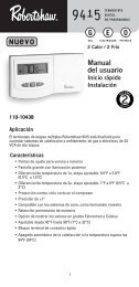
<strong>HORIZONTAL</strong> <strong>TWO</strong>-<strong>WAY</strong> <strong>COIL</strong>INSTALLATION INSTRUCTIONSImportant Safety InstructionsThe following symbols and labels are used throughout thismanual to indicate immediate or potential safety hazards. It isthe owner’s and installer’s responsibility to read and complywith all safety information and instructions accompanying thesesymbols. Failure to heed safety information increases the riskof personal injury, property damage, and/or product damage.WARNINGHIGH VOLTAGE!Disconnect ALL power before servicing.Multiple power sources may be present.Failure to do so may cause property damage,personal injury or death.ONLY individuals meeting the requirements of an“Entry Level Technician”, at a minimum, as specifiedby the <strong>Air</strong> Conditioning, Heating and RefrigerationInstitute (AHRI) may use this information. Attemptingto install or repair this unit without such backgroundmay result in product damage, personal injury,or death.Shipping InspectionUpon receiving the product, inspect it for damage from shipment.Shipping damage, and subsequent investigation is theresponsibility of the carrier. Verify the model number, specifications,electrical characteristics, and accessories are correctprior to installation. The distributor or manufacturer will notaccept claims from dealers for transportation damage or installationof incorrectly shipped units.Codes & RegulationsThis product is designed and manufactured to comply withnational codes. Installation in accordance with such codes and/or prevailing local codes/regulations is the responsibility of theinstaller. The manufacturer assumes no responsibility for equipmentinstalled in violation of any codes or regulations.The United States Environmental Protection Agency (EPA)has issued various regulations regarding the introductionand disposal of refrigerants. Failure to follow theseregulations may harm the environment and can lead tothe imposition of substantial fines. Should you have anyquestions please contact the local office of the EPA.Replacement PartsWhen reporting shortages or damages, or ordering repair parts,give the complete product model and serial numbers as stampedon the product. Replacement parts for this product are availablethrough your contractor or local distributor. For the locationof your nearest distributor consult the white businesspages, the yellow page section of the local telephone book orcontact:© 2005-2006, 2009-2012 Goodman Manufacturing Company, L.P.5151 San Felipe, Suite 500, Houston, TX 77056www.goodmanmfg.com -or- www.amana-hac.comP/N: IO-285H Date: October 2012CONSUMER AFFAIRSGOODMAN MANUFACTURING COMPANY, L.P.7401 SECURITY <strong>WAY</strong>HOUSTON, TEXAS 77040877–254–4729Pre-Installation InstructionsCarefully read all instructions for the installation prior to installingproduct. Make sure each step or procedure is understoodand any special considerations are taken into account beforestarting installation. Assemble all tools, hardware and suppliesneeded to complete the installation. Some items mayneed to be purchased locally. Make sure everything needed toinstall the product is on hand before starting.Application InformationInstall this coil upstream (discharge air) of the furnace andinstall downstream (return air) of the air handler. This coil is bidirectionalcoil and can be installed in either the left or rightdirection. Determine the coil direction by the side that allowsthe best access.RIGHT APPLICATION LEFT APPLICATIONFigure 1Front View (for Right & Left Hand Application)There is no conversion required to reverse from right to leftapplication. Attach the duct flanges to the discharge side ofthe unit. If the coil and furnace combination are not similar indepth and width, use a field-supplied transition to center thefurnace and coil openings (see figure 3). The supplied Z-bracketattachment should be used to attach the coil to a narrowerGoodman or Amana ® furnace when the furnace is one sizesmaller than the coil (i.e. coil height = 17.5-inches and furnacewidth = 14-inches) (See figure 3). Figure 3a indicates incorrectcoil/furnace attachment method.Duct Flange Attachment1. Remove the shipping bracket spanning the A-Coil apexto the rear of the wrapper on all models prior to installation.2. The bottom duct flange for the supply plenum side isshipped unattached. Carefully insert the flange into bottomrail and use a 5/16" screw to attach at the middle ofthe flange.
CAUTIONIf secondary drain is not installed, the secondary accessmust be plugged.NOTE: Trapped lines are required by many local codes. In theabsence of any prevailing local codes, please refer to therequirements listed in the Uniform Mechanical Building Code.A drain trap in a draw-through application prevents air frombeing drawn back through the drain line during fan operationthus preventing condensate from draining, and if connected toa sewer line to prevent sewer gases from being drawn into theairstream during blower operation. In a blow-through applicationthe drain trap prevents conditioned air from escaping. It ispermissible in this application to use a shallow trap designsometimes referred to as a running trap.DrainConnectionDo not use the coil pan shipped with the unit on OILfurnaces or any application where the temperature ofthe drain pan may exceed 300°F. A high temperaturedrain pan such as kits HTP-A, -B, -C and -D for normalcabinet widths of 14, 17.5, 21 and 24.5 inches,respectively, should be used for applications wherethe temperature exceeds 300°F and below 450°F. Afield fabricated metal drain pan can also be used forapplications where temperature exceeds 300°F.Failure to follow this warning may result in propertydamage and/or personal injury.Horizontal Coil Water Blower-Off BracketCHPF4860 coils are shipped with an accessory kit containinga sheet metal bracket. For horizontal-left applications wherethe airflow may exceed 1600 CFM, this bracket must beinstalled on the left side of the drain pan as shown in Figure 6.2" MIN.Cased CoilPOSITIVE LIQUID SEALREQUIRED AT TRAP3" MIN.Figure 4Condensate Drain TrapThe depth of a running trap (Figure 5) should be either 1" or adepth that permits unrestricted condensate drainage withoutexcessive air discharge.Field experience has shown condensate drain traps with anopen vertical Tee between the air handler and the condensatedrain trap can improve condensate drainage in some applications,but may cause excessive air discharge out of the openTee. Goodman® does not prohibit this type of drain but wealso do not recommend it due to the resulting air leakage.Regardless of the condensate drain design used, it is theinstaller’s responsibility to ensure the condensate drain systemis of sufficient design to ensure proper condensate removalfrom the coil drain pan.PITCHTOWARDSDRAIN1” MINTRAPFigure 5Running TrapCONDENSATEDRAIN CONN.CONNECT DRAINSAME SIZE AS ONUNIT OR LARGERRefrigerant LinesWARNINGFigure 6Horizontal Blow-Off BracketA quenching cloth is strongly recommended toprevent scorching or marring of the equipmentfinish when welding close to the painted surfaces.Use brazing alloy of 5% minimum silver content.All cut ends are to be round, burr free, and cleaned. Any othercondition increases the chance of a refrigerant leak. Use apipe cutter to remove the closed end of the spun closed suctionline.To avoid overheating after brazing, quench all welded jointswith water or a wet rag.For the correct tubing size, follow the specification for the condenser/heatpump3
WARNINGThe coil is shipped under pressure. Follow theseinstructions to prevent injury.CAUTIONApplying too much heat to any tube can melt the tube. Torchheat required to braze tubes of various sizes must beproportional to the size of the tube. Service personnel mustuse the appropriate heat level for the size of the tube beingbrazed.NOTE: Tubes of smaller size require less heat to bring thetube to brazing temperature before adding brazing alloy. Theuse of a heat shield when brazing is recommended to avoidburning the serial plate or the finish on the unit.Special InstructionsThis coil comes equipped with a check style flowrator for refrigerantmanagement. For most installations with matching applications,no change to the flowrator orifice is required. However,in mix-matched applications, a flowrator change may berequired. See the Goodman® Piston Kit Chart or consult yourlocal distributor for details regarding mix-matched orifice sizing.If the mix-match application requires a different piston size,change the piston in the distributor on the indoor coil beforeinstalling the coil and follow the procedure shown below.1. Loosen the 13/16 nut 1 TURN ONLY to allow high pressuretracer gas to escape. No gas indicates a possibleleak.2. After the gas has escaped, remove the nut and discardthe black or brass cap.3. Remove the check piston to verify it is correct and thenreplace the piston. See piston kit chart in instructions.4. Use a tube cutter to remove the spin closure on the suctionline.5. Slide the 13/16 nut into place on the tailpiece supplied inthe literature bag or with the unit.6. Braze tailpiece to the line set liquid tube.13/16" NUTTAILPIECEPLASTIC or BRASS CAPWHITETEFLON SEALPISTONFigure 7Flowrator7. Insert the suction line into the connection, slide the insulationand the rubber grommet at least 18" away from thebraze joint. Braze suction line.8. AFTER THE TAILPIECE HAS COOLED, confirm positionof the white Teflon ® seal and hand tighten the 13/16nut.9. Torque the 13/16 nut to 10-25 ft-lbs. or tighten 1/6 turn.CAUTIONExcessive torque can cause orifices to stick. Use the propertorque settings when tightening orifices.10. Replace suction line grommet and insulation.SUCTION LINEWITH SPIN CLOSUREFigure 8Suction Line GrommetRUBBERGROMMET11. Check fittings for leaks after complete installation. Evacuateand charge on the low side.NOTE: With the piston in the distributor, the seal end shouldpoint inside the distributor body and should not be seen whenlooking into the end of distributor. Make sure the piston is freeto rotate, and move up and down in the distributor body.IMPORTANT: Note 2 in the Goodman Piston Kit Chart doesnot apply to CH coils.NOTE: SPECIFICATIONS AND PERFORMANCE DATA LISTED HEREIN ARE SUBJECT TO CHANGE WITHOUT NOTICEVisit our websites at www.goodmanmfg.com or amana-hac.com for information on:• <strong>Products</strong>• Parts• Warranties• Contractor Programs and Training• Customer Service • Financing Options© 2005-2006, 2009-2012 Goodman Manufacturing Company, L.P.4

![Owner's Manual (General) [pdf] - Appliance Factory Parts](https://img.yumpu.com/50830858/1/184x260/owners-manual-general-pdf-appliance-factory-parts.jpg?quality=85)