Direct Vent Tankless Water Heater - Alpine Home Air Products
Direct Vent Tankless Water Heater - Alpine Home Air Products
Direct Vent Tankless Water Heater - Alpine Home Air Products

Create successful ePaper yourself
Turn your PDF publications into a flip-book with our unique Google optimized e-Paper software.
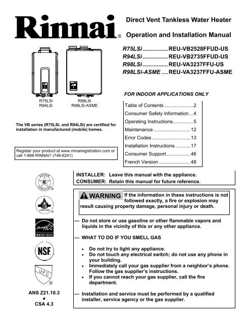
<strong>Direct</strong> <strong>Vent</strong> <strong>Tankless</strong> <strong>Water</strong> <strong>Heater</strong>Operation and Installation ManualR75LSi ................ REU-VB2528FFUD-USR94LSi ................ REU-VB2735FFUD-USR98LSi ................ REU-VA3237FFU-USR98LSi-ASME .... REU-VA3237FFU-ASMER75LSiR94LSiR98LSiR98LSi-ASMEThe VB series (R75LSi, and R94LSi) are certified forinstallation in manufactured (mobile) homes.Register your product at www.rinnairegistration.com orcall 1-866-RINNAI1 (746-6241)FOR INDOOR APPLICATIONS ONLYTable of Contents ..................... 2Consumer Safety Information ... 4Operating Instructions ............... 5Maintenance ........................... 12Error Codes ............................ 13Installation Instructions ........... 17Consumer Support .................. 46French Version ....................... 48INSTALLER: Leave this manual with the appliance.CONSUMER: Retain this manual for future reference.WARNING If the information in these instructions is notfollowed exactly, a fire or explosion mayresult causing property damage, personal injury or death.— Do not store or use gasoline or other flammable vapors andliquids in the vicinity of this or any other appliance.— WHAT TO DO IF YOU SMELL GAS• Do not try to light any appliance.• Do not touch any electrical switch; do not use any phone inyour building.• Immediately call your gas supplier from a neighbor’s phone.Follow the gas supplier’s instructions.• If you cannot reach your gas supplier, call the firedepartment.ANS Z21.10.3●CSA 4.3— Installation and service must be performed by a qualifiedinstaller, service agency or the gas supplier.
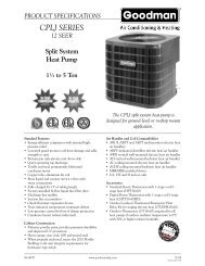
RR98LSi-ASMESpecifications ..................................................... 3Consumer Safety InformationSafety Definitions ............................................. 4Safety Behaviors and Practices ....................... 4Safety Features................................................ 4Description of Operation .................................... 4Operating InstructionsFeatures Available on TemperatureControllers ........................................................ 5Temperature Controllers - Models ............... 6, 7How to Set the Temperature ............................ 8Temperature Controller Settings .................. 8, 9Temperature Options Withouta Temperature Controller ................................. 9Setting the Sound Volume (Voice Prompt) ...... 9Using the <strong>Water</strong> Smart / Bath Fill Function ... 10Overview ................................................... 10Setting the <strong>Water</strong> Volume ......................... 10Filling the Tub ............................................ 11Setting Controller to Mute .............................. 11Setting the Clock ............................................ 11MaintenanceCleaning .................................................... 12<strong>Vent</strong> System .............................................. 12Motors ....................................................... 12Temperature Controller ............................. 12Lime / Scale Build-up ................................ 12Snow Accumulation ................................... 12Visual Inspection of Flame ........................ 12Error CodesError Code Table ...................................... 13,14Trouble Shooting for Common Issues ........... 15Accessing Operating Information................... 15<strong>Water</strong> Quality ................................................. 15Flushing the Heat Exchanger(Error Code: LC or 00) ................................... 16Installation Instructions ................................... 17General Instructions ....................................... 17Clearances from Appliance ............................ 18Attachment of the <strong>Water</strong> <strong>Heater</strong> .................... 18Electrical Connection ..................................... 19Error Indication or <strong>Air</strong> Handler Control Switch ...(R75LSi, R94LSi only) ................................... 19Table of ContentsThis model has been built in accordance withthe requirements of the ASME Boiler andPressure Vessel Code and has received theCertificate of Authorization from the NationalBoard. The heat exchanger on this unit hasthe NB and HLW stamps.California Proposition 65 lists chemical substances known to the state to cause cancer, birth defects, death,serious illness or other reproductive harm. This product may contain such substances, be their origin from fuelcombustion (gas, oil) or components of the product itself.Gas PipingGeneral Instructions ................................ 19Pipe Sizing Procedure - Example ............ 20<strong>Water</strong> PipingGeneral Instructions ................................ 21Pressure Relief Valve .............................. 21Freeze Protection .............................. 21, 22Freeze Protection Piping ............................... 23Recommended Piping for Basic Installation .. 24Recommended Piping forCirculation Systems ....................................... 25Optional Piping for Circulation Systems ........ 26<strong>Vent</strong>ing InstructionsIntake / Exhaust Guidelines ..................... 27Condensate ............................................. 27Maximum <strong>Vent</strong> Length ............................ 28<strong>Vent</strong> <strong>Products</strong> .......................................... 29Flue Terminal Clearances(ANS Z21.10.3, CSA 4.3) .............................. 30Additional Clearances - <strong>Vent</strong> Terminal .......... 31Flue Installation - Concentric <strong>Vent</strong>ing(R75LSi, R94LSi) ........................................... 32Flue Installation(R98LSi, R98LSi-ASME).......................... 33, 34Connecting Multiple <strong>Water</strong> <strong>Heater</strong>s ............... 35High Altitude Installations ........................ 35, 36Temperature Controller InstallationLocation ................................................... 37Configurations.......................................... 37Cable Lengths and Size .......................... 37Mounting the Controller ........................... 38Operating Instructions ................................... 39Technical DataPressure Drop Curve ..................................... 40Outlet Flow Data ............................................ 40Space Heating ............................................... 41Dimensions .................................................... 42Ladder Diagrams ..................................... 43, 44Consumer SupportWarranty Information ..................................... 45Limited Warranty ...................................... 45, 46State Regulations .............................................. 47French Version ............................................ 48-682 VB Series Indoor LS Manual
SpecificationsModel R75LSi R94LSi R98LSi R98LSi-ASMEMinimum Gas Consumption Btu/h9,900 (NG)10,300 (LPG)19,000Maximum Gas Consumption Btu/h 180,000199,000 (NG)190,000 (LP)237,000Hot water capacity (Min - Max) *0.4 - 7.5 GPM(1.5 - 28.5 L/min)0.4 - 9.4 GPM(1.5 - 35.5 L/min)0.6 - 9.8 GPM(2.4 - 37 L/min)Hot water capacity (45°F rise)6.6 GPM(25.0 L/min)7.1 GPM(27.0 L/min)8.5 GPM(32.2 L/min)Default Temperature Setting (no controller) 120º F (49º C)Temperature Controller Default Setting 104º F (40º C)Maximum Temp Setting (commercial **) 160º F (71º C) 185º F (85º C)Maximum Temp Setting (residential)see Temperature Ranges for more informationSelectable at 120º F (49º C) or at 140º F(60º C)Minimum Temperature Setting 98º F (37º C)140º F (60º C)Weight 51 lb (23 kg) 53 lb (24 kg) 55 lb (25 kg)Efficiency Rating 84.0%Noise level49 dBElectrical ConsumptionNormal 76 W 83 W 99 WStandbyAnti-frost Protection 184 W 116 WBy-Pass Control Fixed ElectronicMinimum Gas Supply Natural Gas5.0 inch W.C.PressurePropane8.0 inch W.C.Maximum Gas Supply Natural Gas10.5 inch W.C.PressurePropane13.5 inch W.C.Type of Appliance<strong>Direct</strong> <strong>Vent</strong>, Temperature controlled continuous flow gas hot water system.OperationApproved Gas TypeConnectionsIgnition SystemElectric Connections2 WWith or without remote controls, mounted in kitchen, bathroom, etc.Natural Gas or Propane - Ensure unit matches gas type supplied at the installationGas Supply: 3/4" MNPT, Cold <strong>Water</strong> Inlet: 3/4" MNPT, Hot <strong>Water</strong> Outlet: 3/4" MNPT<strong>Direct</strong> Electronic IgnitionAppliance: AC 120 Volts, 60Hz. Remote Control: DC 12 Volts (Digital)<strong>Water</strong> Temperature Control<strong>Water</strong> Supply PressureMaximum <strong>Water</strong> Supply PressureRemote Control CableSimulation Feedforward and Feedback.Minimum <strong>Water</strong> Pressure: 20 PSI (Recommended 30-80 PSI for maximum150 PSINon-Polarized Two Core Cable (Minimum 22 AWG)Energy Star Qualified Yes Yes No (not applicable)Certified for installation in manufactured (mobile)homesYes Yes No No* Minimum flow may vary slightly depending on the temperature setting and the inlet water temperature.** for commercial and hydronic applications requiring higher temperaturesRinnai is continually updating and improving products. Therefore, specifications are subject to change withoutprior notice.The maximum inlet gas pressure must not exceed the value specified by the manufacturer. The minimum valuelisted is for the purpose of input adjustment.VB Series Indoor LS Manual 3
Safety DefinitionsConsumer Safety InformationThis is the safety alert symbol. This symbol alerts you to potential hazards that can kill or hurt you andothers.DANGERWARNINGCAUTIONIndicates an imminently hazardous situation which, if not avoided, will result in death orserious injury.Indicates a potentially hazardous situation which, if not avoided, could result in death orserious injury.Indicates a potentially hazardous situation which, if not avoided, could result in minor ormoderate injury. It may also be used to alert against unsafe practices.Safety Behaviors and PracticesWARNING• Keep the area around the appliance clear and freefrom combustible materials, gasoline, and otherflammable vapors and liquids.• Any alteration to the appliance or its controls can bedangerous and will void the warranty.• Always check the water temperature before enteringa shower or bath.Safety Features• Overheat: The appliance will automatically shutdown when the appliance exceeds a predeterminedtemperature.• Flame Failure: The appliance will automaticallyshut down if the burner flame is not adequate.• Power Failure: The appliance will cut off the gas ifit loses electrical power.• Do not use this appliance if any part has been underwater. Immediately call a qualified servicetechnician to inspect the appliance and to replaceany part of the control system and any gas controlwhich has been under water.• Power Surge Fuse: A glass fuse protects againstovercurrent. If the fuse blows then all indicatorlamps will be off.• Fusible Link: In case the overheat feature doesnot prevent the temperature from rising then thefusible link will break shutting off the appliance.Description of OperationThe Rinnai water heater is one of the most advancedwater heaters available. It provides a continuoussupply of hot water at a preset temperature. Thisappliance is direct vent where air is brought in from theoutside and combustion gases are exhausted to theoutside.While electricity, water, and gas supplies areconnected, the Rinnai water heater produces hot waterwhenever a hot water tap is open.Ignition is electronic. There is no pilot light consuminggas while the water heater is not being used. The gasburner lights automatically when the hot water tap isopened and goes out when the tap is closed.Installation of the temperature controller is highlyrecommended. The temperature controller can set thetemperature within a specific range and can provideerror codes to diagnose any problems.The temperature of the outgoing hot water is constantlymonitored. The Rinnai water heater may adjust thewater flow in order to maintain the temperature setting.The water flow may vary from summer to winter due tothe difference in ground water temperature.4 VB Series Indoor LS Manual
Operating InstructionsThe MC-91 temperature controller is supplied with the R75LS, R94LS, and R98LS models. Additional functionsare available through the use of optional controllers.There are several models of temperature controllers that can be purchased separately. Their description,operation, and installation is provided in this manual in case additional temperature controllers are purchased andinstalled.Features Available on Temperature ControllersFeaturesMC-91MCC-91MC-100BC-100MC-502DescriptionCallSends a short series of beeps to all controllers in the system. It isnot an intercom.Clock12 hour AM/PM clock. (The MC-100 must be installed for clockto work on the BC-100.)Error CodesWhen a fault is detected an error code flashes at the temperaturedisplay on models MC-91, MCC-91, and MC-502; and flashes atthe clock display on models MC-100 and BC-100.FunctionUsed on this model to set the clock or sound volume.In Use IndicatorIndicates that hot water is being supplied (i.e. a hot water tap isopen).ON/OFF ButtonUsed to turn the water heater ON or OFF.Power SaveAllows the temperature controller to be in an energy savingmode.Priority Button /IndicatorIndicates that this controller is setting the temperature . Prioritycan be switched to another controller by pressing its PriorityButton when no hot water is running.Sound VolumeUsed to adjust the voice prompt volume.Temperature DisplayShows the temperature setting.ThermostatIncreases or decreases the temperature setting.<strong>Water</strong> Smart / Bath FillButton / IndicatorUsed to select the <strong>Water</strong> Smart / Bath Fill Function to fill a bathwith a predetermined volume of water.<strong>Water</strong> VolumeUsed to select the water volume for the <strong>Water</strong> Smart / Bath FillFunction.VB Series Indoor LS Manual 5
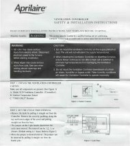
Temperature Controllers - ModelsDimensions (inches): 3.5 W x 4.75 H x 0.75 DMC-91-1US & MCC-91-1USThe MC-91 controller is the standard temperature controller that is supplied with the water heater. On indoormodels it is integrated into the front panel. The MCC-91 controller is for commercial and hydronic applicationsrequiring higher temperatures. When the MCC-91 controller is connected, these higher temperatures areavailable on all controller models in the system. Refer to the section on temperature ranges.In UseIndicatorTemperatureDisplayTemperatureSelectionPriorityIndicatorPriorityButtonON/OFFButtonDimensions (inches): 4.33 W x 5.90 H x 1.16 DMC-502RC-1US-S * (Wireless)TemperatureDisplayTemperatureSelectionON/OFFButtonPriorityIndicatorIn UseIndicatorPriorityButton* Requires the transceiver, MC-502RC-1US-M, to be connected tothe water heater.Refer to the MC-502RC-1US-S manual and the Wireless Controller Installation Instructions for complete detailson features, operation, and installation.6 VB Series Indoor LS Manual
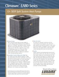
Temperature Controllers - ModelsDimensions (inches): 8.0 W x 4.125 H x 0.875 DBC-100V-1USNOTICEThe BC-100V controller is water resistant. Avoid splashing the controller.In UseIndicatorTemperatureDisplay<strong>Water</strong> SmartBath Fill IndicatorPriorityButton andIndicatorCallON/OFFButton<strong>Water</strong> SmartBath FillButtonClockPower Save<strong>Water</strong> VolumeTemperatureSelectionSound VolumeDimensions (inches): 5.0 W x 4.75 H x 0.75 DMC-100V-1USIn UseIndicatorTemperatureDisplayClockTemperatureSelectionFunctionPriority Buttonand IndicatorCallON/OFFButtonVB Series Indoor LS Manual 7
How to Set the TemperatureDANGERHot water can be dangerous, especially for infants or children, the elderly,or infirm. There is hot water scald potential if the thermostat is set too high.<strong>Water</strong> temperatures over 125º F (52º C) can cause severe burns orscalding resulting in death.Hot water can cause first degree burns with exposure for as little as:3 seconds at 140º F (60º C)20 seconds at 130º F (54º C)8 minutes at 120º F (49º C)Test the temperature of the water before placing a child in the bath orshower.Do not leave a child or an infirm person in the bath unsupervised.1. If the water heater is off, pressthe ON/OFF button to turn on.2. Press the “Priority button” on thetemperature controller. Thegreen Priority light will glowindicating that this controller iscontrolling the temperature andthat the Rinnai water heater isready to supply hot water.The priority can only be changedwhile no hot water is running.3. Press the ▲ or ▼ buttons toobtain the desired temperaturesetting.All hot water sources are able toprovide water at this temperaturesetting until it is changed again atthis or another temperaturecontroller.Temperature Controller SettingsNOTICENOTICENOTICENOTICEWhile any hot water is being provided,the temperature setting can only beadjusted between 98º F and 110º F.Check local codes for the maximumwater temperature setting allowedwhen used in nursing homes, schools,day care centers, and all other publicapplications.If a newly installed unit with acontroller has not been powered for atleast 6 hours then the temperature willreturn to the default setting of 104º F(40º C) if power is interrupted.There may be a variation between thetemperature displayed on thetemperature controller and thetemperature at the tap due to weatherconditions or the length of pipe to thewater heater.This water heater will attempt to provide hot water at the temperature setting even when the water flow is variedor when more than 1 tap is in use. The water heater can deliver water at only one temperature setting at a time.The available temperatures for a given model are provided below.ModelR75LSi 98 100 102 104 106 108 110 115 120R98LSiR98LSi-ASMETemperature Settings Available (ºF)R94LSi 98 100 102 104 106 108 110 115 1208 VB Series Indoor LS Manual125*130*135*140*98 100 102 104 106 108 110 115 120 125 130 135 140Temp in Celsius ºC 37 38 39 40 41 42 43 46 49 52 54 57 60 66 71 85An older controller, MC-45, can be installed with the R75LSi and R94LSi by moving switch No. 6 in the bank of 6switches to ON. Some of the temperature settings will be slightly different from the above table.125*130*135*140*150**150**150**160**160**160**185**185**
Temperature Controller Settings* Re-setting the Maximum Temperature (R75LS and R94LS only)Models R75LS and R94LS have a default maximum temperature of 120ºF (49º C) and an option to increase the maximum temperature to 140 ºF(60 ºC). Temperature settings from 125-140 ºF (52-60 ºC) are availableby setting switch 6 to ON in the SW1 bank of 8 switches.** MCC-91 Temperature ControllerThese settings require the MCC-91 controller. When the MCC-91controller is connected, these higher temperatures are available on allcontroller models in the system. Use of an MCC-91 controller in aresidential dwelling will reduce the warranty coverage to that of acommercial warranty application.The MCC-91 controller is intended for commercial and hydronicapplications only. If an MCC-91 controller is used in a residentialdwelling for a hydronics application, a mixing valve must also beinstalled to limit the potable hot water temperature to a safetemperature. <strong>Water</strong> temperatures over 125º F (52º C) can cause severeburns or scalding. Refer to the Danger Alert on water temperatures.Rinnai shall not, in any event, be liable for damages resulting from suchmisuse or misapplication.Maximum Temperature120º F (49º C) 140 ºF (60 ºC)Switch No.Switch No.OFFON12345678WARNINGOFFON12DO NOT adjust the other switchesunless specifically instructed to doso.345678Suggested temperatures are• Kitchen 120 ºF (49º C)• Shower 98 - 110 ºF (37 - 43 ºC)• Bath Fill 102 - 110 ºF (39 - 43 ºC)These temperatures are suggestions only.A temperature lower than 98º F (37º C) can beobtained at the tap by mixing with cold water.To change the temperature scale from Celsius toFahrenheit or vice versa, press and hold the “On/Off”button for 5 seconds while the water heater is OFF.Temperature Options Without a Temperature ControllerThe default temperature setting for this appliance installed without a temperature controller is 120º F (49º C). Ifdesired, the temperature setting can be changed to 140º F (60º C) by adjustment of a switch.In the SW1 bank of 8 switches, set switch 5 to ON to obtain 140º F water temperature setting. Set switch 5 toOFF (default) to obtain 120º F water temperature setting.If a temperature controller is installed, then switch 5 has no effect on temperature settings.Setting the Sound Volume (Voice Prompt)MC-100VPress the “Function” button toadjust the voice promptvolume. The default soundvolume is set to Medium.Each subsequent press of the▲ or ▼ button cycles throughthe volume levels in the orderbelow.BC-100VPress the “Sound Vol.” button toadjust the voice prompt volume.The default sound volume is setto Medium. Each subsequentpress of the button cyclesthrough the volume levels in theorder below.Medium Volume(default)High VolumeOff Volume(beep)Off Sound(no beep)Low VolumeVB Series Indoor LS Manual 9
Using the <strong>Water</strong> Smart / Bath Fill FunctionOverviewThis function is exclusive to the BC-100V temperaturecontroller. The bath fill function allows the consumerto fill a tub with a preset volume of water at a presettemperature. This is done by pressing the bath fillbutton on the BC-100V controller while no hot water isflowing and then opening only the hot water tap. Thewater heater will stop the hot water flow when thepreset volume has been reached. The hot water tapshould then be closed and the bath fill button pressed.The temperature settings for the bath fill function arelimited to those in the table below.Bath Fill Temperature SettingsAvailableºF 98 100 102 104 106 108ºC 37 38 39 40 41 42ºF 110 112 114 116 118 120ºC 43 44 46 47 48 49NOTICEMultiple<strong>Water</strong><strong>Heater</strong>sNOTICEPowerLossNOTICEAnti-scaldFixturesThe bath fill function will not workproperly if it is connected to multiplewater heaters. The tub will overfillbecause the bath fill function is notable to measure the water volumewhen connected to multiple waterheaters.If power is lost during the bath fillfunction, the water heater will shutdown but the water will continue toflow. When power returns, the watershuts off and Error Code 03 appearson the controller.If power is lost after the bath has filledbut before the bath fill function buttonis de-selected, then the water will notflow during the power loss or after thepower is returned. Once powerreturns, close the hot water tap andde-select the bath fill function. Noerror code appears.Do not use with single handle fixturesthat have anti-scald features built intothem. These fixtures allow apredetermined amount of cold waterwhich is not taken into account by thebath fill function.Setting the <strong>Water</strong> VolumeThe default volume is set to 25 gallons. The volumecan be set between 10 and 120 gallons.1. Press the “Priority” button on thetemperature controller. The greenPriority light will glow indicatingthat this controller is controllingthe temperature and that theRinnai water heater is ready tosupply hot water.4. Press the “<strong>Water</strong> Vol.”▲ or ▼buttons to obtain the desiredwater volume in gallons.5. Press the “<strong>Water</strong> Smart Bath Fill”button.2. Press the “<strong>Water</strong> Smart Bath Fill”button to set the water volumeand temperature.3. Press the “Temp” ▲ or ▼ buttonsto obtain the desired temperaturesetting.NOTICETo PreventOver FillingBe careful not to overfill the bath. Anaverage bath volume is 60 gallons.When filling the bath using thisfunction for the first time:•Monitor and remain by the bath whilethe water is running.•Use a low bath fill volume less than25 gallons10 VB Series Indoor LS Manual
Using the <strong>Water</strong> Smart / Bath Fill FunctionFilling the Tub1. Press the “<strong>Water</strong> Smart / Bath Fill”button once. The button willilluminate, and a tone will sound.2. The voice prompt will announce“The hot water system is ready.Open the hot water tap.”ON! COLD Make sure the water volume is set.Refer to “Setting the <strong>Water</strong>Volume” on the previous page.Open the hot water tap. The “InHOTUse” indicator will illuminate onON! COLDMC-100V and BC-100V controllers.The hot water will begin to flow.3. When the preset volume of waterhas been produced thenHOT•the water flow will cease•the “<strong>Water</strong> Smart / Bath Fill”button will flash•a tone will sound•the voice prompt will announce,“Bath fill is complete. Turnoff the bath hot water tap andpush the Bath Fill button.”4. Turn off the bath hot water tap andpush the Bath Fill button. Thewater heater will not allow hotwater to flow from any source untilthe “<strong>Water</strong> Smart / Bath Fill” buttonis pushed.The button light will go out.NOTICETo Stop theBath FillBefore itFinishesNOTICEWhenOther TapsAre OpenNOTICETo stop the water flow during the BathFill function, press the “<strong>Water</strong> Smart /Bath Fill” button. The button will flashand the voice prompt will announce,“Hot water is not available. Turn offall hot water taps and push the BathFill button.” Follow the voice promptinstructions.During the bath fill function, any hotwater flowing at other locations,subtracts from the total amount ofwater for the bath. For example if thebath fill function is set for 50 gallonsand 5 gallons of hot water are used atother locations during the fill periodthen the bath will only fill with 45gallons.During the operation of the bath fillfunction, the MC-91 “In Use” indicatordoes not light up.Setting Controller to MuteModels MC-91 and MCC-91To eliminate the beeps when keys are pressed or to turn the beeps back on, press and hold both the ▲and ▼buttons until a beep is heard (approximately 5 seconds).Setting the ClockMC-100VPress the “Function” button twice within 10 seconds to set the clock. Press the ▲ or▼ button to reach the desired time. The clock on the BC-100V automatically showsthe time which has been set on the MC-100V.VB Series Indoor LS Manual 11
MaintenanceWARNINGTurn off the electrical power supply, the manual gasvalve and the manual water control valve wheneverservicing the unit.Repairs and maintenance should be performed by aqualified service technician. The appliance should beinspected annually by a qualified service technician.Verify proper operation after servicing.CleaningIt is imperative that control compartments, burners,and circulating air passageways of the appliance bekept clean.Clean as follows:1. Turn off and disconnect electrical power. Allow tocool.2. Close the water shut off valves. Remove and cleanthe water inlet filter.3. Remove the front panel by removing 4 screws.4. Use pressurized air to remove dust from the mainburner, heat exchanger, and fan blades. Do notuse a wet cloth or spray cleaners on the burner.Do not use volatile substances such as benzeneand thinners. They may ignite or fade the paint.5. Use soft dry cloth to wipe cabinet.<strong>Vent</strong> SystemThe vent system should be inspected at least annuallyfor blockages or damage.MotorsMotors are permanently lubricated and do not needperiodic lubrication. Keep fan and motor free of dustand dirt by cleaning annually.Temperature ControllerUse a soft damp cloth to clean the temperaturecontroller. Do not use solvents.Lime / Scale Build-upIf you receive Error Code “LC”, refer to the procedure,Flushing the Heat Exchanger. Refer to the section on<strong>Water</strong> Quality to see if your water needs to be treatedor conditioned. (When checking maintenance codehistory, “00” is substituted for “LC”.)Snow AccumulationKeep the area around flue terminal free of snow andice. The appliance will not function properly if theintake air or exhaust is impeded (blocked or partiallyblocked) by obstructions.Visual Inspection of FlameThe burner must flame evenly over the entire surfacewhen operating correctly. The flame must burn with aclear, blue, stable flame. See the parts breakdown ofthe burner for the location of the view ports.The flame pattern should be as shown in the figuresbelow.12 VB Series Indoor LS Manual
Error CodesThe Rinnai water heater has the ability to check its own operation continuously. If a fault occurs, an error codewill flash on the display of the temperature controller. This assists with diagnosing the fault and may enable youto overcome a problem without a service call. Please identify the code displayed when inquiring about service.WARNINGSome of the checks below may need to be done by a qualified service technician. Call aservice technician for any remedy that involves gas or electricity. Call a servicetechnician if you have any doubt or reservation about performing the remedy yourself.Code Fault Remedy02 No burner operation during Service Callfreeze protection mode03 Power interruption duringBath Fill (<strong>Water</strong> will not flowwhen power returns).10 <strong>Air</strong> Supply or ExhaustBlockageTurn off all hot water taps. Press ON/OFF twice.Ensure Rinnai approved venting materials are being used.Check that nothing is blocking the flue inlet or exhaust.Check all vent components for proper connections.Ensure vent length is within limits.Ensure condensation collar was installed correctly.Verify dip switches are set properly.Check fan for blockage.11 No Ignition Check that the gas is turned on at the water heater, gas meter, or cylinder.Ensure gas type and pressure is correct.Ensure gas line, meter, and/or regulator is sized properly.Bleed all air from gas lines.Verify dip switches are set properly.Ensure appliance is properly grounded.Disconnect EZConnect or MSA controls to isolate the problem.Ensure igniter is operational.Check igniter wiring harness for damage.Check gas solenoid valves for open or short circuits.Remove burner cover and ensure all burners are properly seated.Remove burner plate and inspect burner surface for condensation or debris.12 Flame Failure Check that the gas is turned on at the water heater and gas meter. Check forobstructions in the flue outlet.Ensure gas line, meter, and/or regulator is sized properly.Ensure gas type and pressure is correct.Bleed all air from gas lines.Ensure proper Rinnai venting material was installed.Ensure condensation collar was installed properly.Ensure vent length is within limits.Verify dip switches are set properly.Ensure appliance is properly grounded.Disconnect keypad.Disconnect EZConnect or MSA controls to isolate the problem.Check power supply for loose connections.Check power supply for proper voltage and voltage drops.Ensure flame rod wire is connected.Check flame rod for carbon build-up.Disconnect and reconnect all wiring harnesses on unit and PC board.Check for DC shorts at components.Check gas solenoid valves for open or short circuits.Remove burner plate and inspect burner surface for condensation or debris.Check the ground wire for the PC board.VB Series Indoor LS Manual 13
Code Fault RemedyError Codes14 Thermal Fuse Check gas type of unit and ensure it matches gas type being used.Check for restrictions in air flow around unit and vent terminal.Check for low water flow in a circulating system causing short-cycling.Ensure dip switches are set to the proper position.Check for foreign materials in combustion chamber and/or exhaust piping.Check heat exchanger for cracks and/or separations.Check heat exchanger surface for hot spots which indicate blockage due to scale build-up.Refer to instructions in manual for flushing heat exchanger.Measure resistance of safety circuit.Ensure high fire and low fire manifold pressure is correct.16 Over TemperatureWarning31 Burner Sensor Error Measure resistance of sensor.32 Outgoing <strong>Water</strong>Temperature SensorFault33 Heat ExchangerOutgoing TemperatureSensor Fault34 Combustion <strong>Air</strong>Temperature SensorFaultCheck for improper conversion of product.Check for restrictions in air flow around unit and vent terminal.Check for low water flow in a circulating system causing short-cycling.Check for foreign materials in combustion chamber and/or exhaust piping.Check for clogged heat exchanger.Replace sensor.Check sensor wiring for damage.Measure resistance of sensor.Clean sensor of scale build-up.Replace sensor.Check sensor wiring for damage.Measure resistance of sensor.Clean sensor of scale build-up.Replace sensor.Check for restrictions in air flow around unit and vent terminal.Check sensor wiring for damage.Measure resistance of sensor.Clean sensor of scale build-up.Ensure fan blade is tight on motor shaft and is in good condition.Replace sensor.Check modulating gas solenoid valve wiring harness for loose or damaged terminals.Measure resistance of valve coil.52 Modulating SolenoidValve Signal Abnormal61 Combustion Fan Failure Ensure fan will turn freely.Check wiring harness to motor for damaged and/or loose connections.Measure resistance of motor winding.65 <strong>Water</strong> Flow Control Fault The water flow control valve has failed to close during the bath fill function. Immediately turnoff the water and discontinue the bath fill function. Contact a state qualified or licensedcontractor to service the appliance.71 Solenoid Valve CircuitFault72 Flame Sensing DeviceFault73 Burner Sensor CircuitErrorLCNocodeScale Build-up in HeatExchanger (whenchecking maintenancecode history, “00” issubstituted for “LC”)Nothing happens whenwater flow is activated.Replace the PC Board.Ensure flame rod is touching flame when unit fires.Check all wiring to flame rod for damage.Remove flame rod and check for carbon build-up; clean with sand paper.Check inside burner chamber for any foreign material blocking flame at flame rod.Measure micro amp output of sensor circuit with flame present.Replace flame rod.Check sensor wiring and PC board for damage.Replace sensor.Flush heat exchanger. Refer to instructions in manual.Replace heat exchanger.NOTE: The LC code is the only error code that will allow the unit to keep running. Thedisplay will alternate between the LC code and the temperature setting. The controller willcontinue to beep. The LC code will reset if power is turned off and then on.Clean inlet water supply filter.On new installations ensure hot and cold water lines are not reversed.Check for bleed over. Isolate unit from building by turning off cold water line to building.Isolate the circulating system if present. Open your pressure relief valve; if water isflowing, there is bleed over in your plumbing.Ensure you have at least the minimum flow rate required to fire unit.Ensure turbine spins freely.Measure the resistance of the water flow control sensor.Check for DC shorts at components.14 VB Series Indoor LS Manual
Trouble Shooting for Common IssuesI don’t have any hot water when I open the tap.Make sure there is gas, water, and electricity to theRinnai water heater (power is turned on and the gas isturned on).When I was using the hot water, the water got cold.If you adjusted the flow from the tap to lessen it, youmay have gone below the minimum flow required. TheRinnai water heater requires a minimum flow rate tooperate. (See the specification page for the flow rateof your model.)If you are experiencing issues with higher temperaturesettings, then Rinnai recommends reducing thetemperature setting. Selecting a temperature closer tothat which is actually used at the faucet will increasethe amount of hot water being delivered to the faucet,due to less cold water mixing at the fixture.White smoke comes out of the exhaust.During colder weather when the exhaust temperatureis much hotter than the outside air, the exhaust fumescondense producing water vapor.When I open a hot tap, I do not immediately get hotwater.Hot water must travel through your plumbing from theRinnai water heater to the faucet. The time period forhot water to reach your fixture is determined by theamount of water in the plumbing system between thewater heater and the fixture, water pressure, and theflow rate of the fixture.After I turn off the hot water tap, the fan on theRinnai water heater continues to run.The fan is designed to continue running for a short timeafter the flow of water stops. This is to ensure constantwater temperatures during rapid starting and stopping,as well as exhausting any residual gas flue productsfrom the unit.Accessing Operating InformationModels MC-91 and MCC-91To display the most recent error codes press and hold the “On/Off” button for 2 seconds. While holding the “On/Off” button press the ▲ button. The last 9 error codes will flash one after the other. To exit this mode press the“On/Off” and ▲ button as before.To display the water flow through the water heater press and hold the ▲ button for 2 seconds and withoutreleasing the ▲ button press the “On/Off” button.To display the outlet water temperature press and hold the ▼ button for 2 seconds and without releasing the ▼button press the “On/Off” button.<strong>Water</strong> QualityConsideration of care for your water heater shouldinclude evaluation of water quality. If the water qualityexceeds the target levels provided in the table, youmay want to treat or condition the water.* Source: Part 143 National Secondary Drinking <strong>Water</strong>RegulationsTotal HardnessAluminum *Chlorides *Copper *Iron *Manganese *Maximum LevelUp to 200 mg / LUp to 0.2 mg / LUp to 250 mg / LUp to 1.0 mg / LUp to 0.3 mg / LUp to 0.05 mg / LpH * 6.5 to 8.5TDS (Total DissolvedSolids) *Zinc *Up to 500 mg / LUp to 5 mg / LVB Series Indoor LS Manual 15
Flushing the Heat Exchanger (Error Code: LC or 00)An “LC” or “00” error code indicates the unit is beginning to lime up and must be flushed. Failure to flush theappliance will cause damage to the heat exchanger. Damage caused by lime build-up is not covered by the unit’swarranty. After flushing, reset the LC fault code by turning off the power to the unit and turning the power backon.1. Disconnect electrical power to the water heater.2. Close the shutoff valves on both the hot water andcold water lines (V3 and V4).3. Connect pump outlet hose (H1) to the cold waterline at service valve (V2).4. Connect drain hose (H3) to service valve (V1).5. Pour 4 gallons of undiluted virgin, food grade,white vinegar into pail.6. Place the drain hose (H3) and the hose (H2) tothe pump inlet into the cleaning solution.7. Open both service valves (V1 and V2) on the hotwater and cold water lines.8. Operate the pump and allow the cleaning solutionto circulate through the water heater for 1 hour ata rate of 4 gallons per minute (15.1 liters perminute).9. Turn off the pump.10. Rinse the cleaning solution from the water heateras follows:a. Remove the free end of the drain hose (H3)from the pail.b. Close service valve, (V2), and open shutoffvalve, (V4). Do not open shutoff valve, (V3).c. Allow water to flow through the water heater for5 minutesd. Close service valve, (V1), and open shutoffvalve, (V3).11. Disconnect all hoses.12. With (V4) closed, remove the in-line filter at thecold water inlet and clean out any residue. Placefilter back into unit and open (V4).13. Restore electrical power to the water heater.3/4" Ball Valve3/4" UnionCheck ValvePressure Relief ValveV1KEYS<strong>Water</strong> <strong>Heater</strong>V2In-lineFilterPressure RegulatorCirculating PumpBoiler Drain ValveSolenoid ValveGas SupplyCLEAN THERMISTORSRemove and clean thermistorswith a soft cloth or sponge afterremoving O-rings.H3Hot <strong>Water</strong> LineV3V4Cold <strong>Water</strong> LineCleaning solution is 4 gallons ofundiluted virgin, food grade,white vinegar.H2Circulating PumpH116 VB Series Indoor LS Manual
Only properly trained and qualified installersshould install this appliance. The warranty maybe voided due to improper installation orinstallation by a non-qualified installer.Rinnai highly recommends all installers attend aproduct knowledge class.For information on a Rinnai Training Course orfor questions on installation call 1-800-621-9419.General InstructionsInstallation InstructionsR75LSi ................ REU-VB2528FFUD-USR94LSi ................ REU-VB2735FFUD-USR98LSi ................ REU-VA3237FFU-USR98LSi-ASME .... REU-VA3237FFU-ASMEThe VB series (R75LSi, and R94LSi) are certified forinstallation in manufactured (mobile) homes.WARNINGDo not use substitute materials.Use only parts certified with the appliance.• This appliance must be installed by a state qualifiedor licensed contractor. It is the responsibility of theperson having the water heater installed to ensurethe installing contractor has proper licenses andpermits for installing water heaters in your location.Rinnai highly recommends that installers attend aproduct knowledge class to ensure customersatisfaction and warranty coverage. Failure tocomply with state and local codes pertaining towater heater installations may void the warranty.• This appliance is not to be installed outdoors.• A qualified installer or service technician shouldinstall the appliance, inspect it, and leak test itbefore use.• The installation must conform with local codes or, inthe absence of local codes, with the National FuelGas Code, ANSI Z223.1/NFPA 54, or the NaturalGas and Propane Installation Code, CSA B149.1. Ifinstalled in a manufactured home, the installationmust conform with the Manufactured <strong>Home</strong>Construction and Safety Standard, Title 24 CFR,Part 3280 and/or CAN/SCA Z240 MH Series, Mobile<strong>Home</strong>s.• The appliance, when installed, must be electricallygrounded in accordance with local codes or, in theabsence of local codes, with the National ElectricalCode, ANSI/NFPA 70, or the Canadian ElectricalCode, CSA C22.1.• The appliance and its appliance main gas valvemust be disconnected from the gas supply pipingsystem during any pressure testing of that system attest pressures in excess of 1/2 psi (3.5 kPa) (13.84in W.C.).• The appliance must be isolated from the gas supplypiping system by closing its individual manualshutoff valve during any pressure testing of the gassupply piping system at test pressures equal to orless than 1/2 psi (3.5 kPa) (13.84 in W.C.).• Follow the installation instructions and those in Careand Maintenance for adequate combustion andventilation air.• The appliance should be located in an area wherewater leakage of the unit or connections will notresult in damage to the area adjacent to theappliance or to lower floors of the structure. Whensuch locations cannot be avoided, it isrecommended that a suitable drain pan, adequatelydrained, be installed under the appliance. The panmust not restrict combustion air flow.• The flow of combustion and ventilation air shall notbe obstructed. Combustion air shall not be suppliedfrom occupied spaces.• This appliance is not suitable for use in anapplication such as a pool or spa heater that useschemically treated water . (This appliance issuitable for filling large or whirlpool bath tubs withpotable water.)• If a water heater is installed in a closed water supplysystem, such as one having a backflow preventer inthe cold water supply line, means shall be providedto control thermal expansion. Contact the watersupplier or local plumbing inspector on how tocontrol thermal expansion.• Should overheating occur or the gas supply fail toshut off, turn off the manual gas control valve to theappliance.• Keep the air intake location free of chemicals suchas chlorine or bleach that produce fumes. Thesefumes can damage components and reduce the lifeof your appliance.• For gas type conversion, contact Rinnai.VB Series Indoor LS Manual 17
Clearances from Applianceto Combustiblesto Non-Combustiblesto topR75LSiR94LSiR98LSiR75LSiR94LSiR98LSiTop of<strong>Heater</strong>Back of<strong>Heater</strong>6 inches **(152 mm)12 inches(305 mm)2 inches **(51 mm)2 inches(51 mm)0 (zero) 0 (zero) 0 (zero) 0 (zero)to sideFront of<strong>Heater</strong>6 inches(152 mm)6 inches(152 mm)6 inches(152 mm)6 inches(152 mm)Sides of<strong>Heater</strong>Ground/Bottom2 inches(51 mm)12 inches(305 mm)2 inches(51 mm)12 inches(305 mm)1/2 inch(13 mm)12 inches(305 mm)1/2 inch(13 mm)2 inches(51 mm)to front<strong>Vent</strong>0 (zero) 4 inches * 0 (zero) 0 (zero)to ground/bottom* 4 inches (102 mm) for enclosed area; 1 inch (26 mm) for unenclosed area.** 0 inches from vent components and condensate drain line.The clearance for servicing is 24 inches in front of the water heater.For closet installation: clearance is 6 inches (152 mm) from the front.Attachment of the <strong>Water</strong> <strong>Heater</strong>1. Identify the installation location and confirm thatthe installation will meet all required clearances.2. Securely attach the water heater to the wall usingany of the holes in the wall installation bracketswhich are at the top and bottom of the waterheater. Ensure that the attachment strength issufficient to support the weight. Refer to theweight of the water heater in the Specificationssection.NOTE: Rinnai water heaters should be installed in anupright position. Do not install upside down or on itsside.wall installationbrackets18 VB Series Indoor LS Manual
Electrical ConnectionThe water heater requires 120 VAC, 60 Hz power from a properly grounded circuit.If using the 6 foot long power cord, plug it into a standard 3 prong 120 VAC, 60 Hz properly grounded wall outlet.The wiring diagram is located on the Technical Sheet attached to the inside of the front cover.The water heater must be electrically grounded in accordance with local codes, or in the absence of local codeswith the National Electrical Code, ANSI/NFPA 70 and/or the CSA C22.1, Canadian Electrical Code.Error Indication or <strong>Air</strong> Handler Control Switch (R75LSi, and R94LSi only)When using the Rinnai water heater with an Error Indication Switch, switch No. 4 in the bank of 8 switches shouldbe in the off position. This is the default position.To connect the water heater to the Rinnai <strong>Air</strong> Handler, the Control Switch is necessary to function as the electricalconnection. When the Control Switch is functioning as the electrical connection between the water heater and airhandler, switch No. 4 in the bank of 8 switches should be in the on position.The Error Indication Switch and the Rinnai <strong>Air</strong> Handler Control Switch are optional products available from Rinnai.Installation instructions are included with these products.Gas PipingGeneral Instructions• A manual gas control valve must be placed in thegas supply line to the Rinnai water heater. A unioncan be used on the connection above the shut offvalve for the future servicing or disconnection of theunit.• Check the type of gas and the gas inlet pressurebefore connecting the Rinnai water heater. If theRinnai water heater is not of the gas type that thebuilding is supplied with, DO NOT connect the waterheater. Contact the dealer for the proper unit tomatch the gas type.• Check the gas supply pressure immediatelyupstream at a location provided by the gascompany. Supplied gas pressure must be within thelimits shown in the Specifications section.• Before placing the appliance in operation all jointsincluding the heater must be checked for gastightness by means of leak detector solution, soapand water, or an equivalent nonflammable solution,as applicable. (Since some leak test solutions,including soap and water, may cause corrosion orstress cracking, the piping shall be rinsed with waterafter testing, unless it has been determined that theleak test solution is non-corrosive.)• Always use approved connectors to connect the unitto the gas line. Always purge the gas line of anydebris before connection to the water heater.• The gas supply line shall be gas tight, sized, and soinstalled as to provide a supply of gas sufficient tomeet the maximum demand of the heater and allother gas consuming appliances at the locationwithout loss of pressure.• Any compound used on the threaded joint of the gaspiping shall be a type which resists the action ofliquefied petroleum gas (propane / LPG).• Refer to an approved pipe sizing chart if in doubtabout the size of the gas line.VB Series Indoor LS Manual 19
Gas PipingPipe Sizing Procedure - ExampleThe gas supply must be capable of handling the entire gas load at the location. Gas line sizing is based on gastype, the pressure drop in the system, the gas pressure supplied, and gas line type. For gas pipe sizing in theUnited States, refer to the National Fuel Gas Code, NFPA 54. For Canadian gas pipe sizing, refer to the NaturalGas and Propane Installation Code CAN/CSA B149.1. The below information is provided as an example. Theappropriate table from the applicable code must be used.1. For some tables, you will need to determine the cubic feet per hour of gas required by dividing the gas inputby the heating value of the gas (available from the local gas company). The gas input needs to include all gasproducts at the location and the maximum BTU usage at full load when all gas products are in use.Gas Input of all gas products (BTU / HR)Cubic Feet per Hour (CFH) =Heating Value of Gas (BTU / FT 3 )2. Use the table for your gas type and pipe type to find the pipe size required. The pipe size must be able toprovide the required cubic feet per hour of gas or the required BTU/hour.Example: The heating value of natural gas for your location is 1000 BTU/FT 3 . The gas input of the R94LSi is199,000 BTU/HR. Additional appliances at the location require 65,000 BTU/hr. Therefore the cubicfeet per hour = (199,000 + 65,000) / 1000 = 264 FT 3 /HR. If the pipe length is 10 feet then the 3/4 inchpipe size is capable of supplying 264 FT 3 /HR of natural gas.Pipe Sizing Table - Natural GasSchedule 40 Metallic PipeInlet Pressure: less than 2 psi (55 inches W.C.)Pressure Drop: 0.3 inches W.C.Specific Gravity: 0.60Capacity in cubic feet per hourLengthPipe Size (inches)3/4 1 1 1/4 1 1/210 273 514 1060 158020 188 353 726 109030 151 284 583 87340 129 243 499 74750 114 215 442 66260 104 195 400 60070 95 179 368 55280 89 167 343 51490 83 157 322 482100 79 148 304 455125 70 131 269 403150 63 119 244 366175 58 109 224 336200 54 102 209 313Pipe Sizing Table - Propane GasSchedule 40 Metallic PipeInlet Pressure: 11.0 inches W.C.Pressure Drop: 0.5 inches W.C.Specific Gravity: 1.50Capacity in Thousands of BTU per HourLengthPipe Size (inches)1/2 3/4 1 1 1/410 291 608 1150 235020 200 418 787 162030 160 336 632 130040 137 287 541 111050 122 255 480 98560 110 231 434 89280 101 212 400 821100 94 197 372 763125 89 185 349 716150 84 175 330 677175 74 155 292 600200 67 140 265 54320 VB Series Indoor LS Manual
<strong>Water</strong> PipingGeneral Instructions• A manual water control valve must be placed in thewater inlet connection to the Rinnai water heaterbefore it is connected to the water line. Unions maybe used on both the hot and cold water lines forfuture servicing and disconnection of the unit.• The piping (including soldering materials) andcomponents connected to this appliance must beapproved for use in potable water systems.• Purge the water line to remove all debris and air.Debris will damage the Rinnai water heater.Pressure Relief Valve• An approved pressure relief valve is required by theAmerican National Standard (ANSI Z21.10.3) /Canadian Standard (CSA 4.3) for all water heatingsystems, and shall be accessible for servicing.• The relief valve must comply with the standard forRelief Valves and Automatic Gas Shutoff Devicesfor Hot <strong>Water</strong> Supply Systems ANSI Z21.22 and /orthe standard Temperature, Pressure, Temperatureand Pressure Relief Valves and Vacuum ReliefValves, CAN1-4.4.• The relief valve must be rated up to 150 psi and toat least the maximum BTU/hr of the appliance.• The discharge from the pressure relief valve shouldbe piped to the ground or into a drain system toprevent exposure or possible burn hazards tohumans or other plant or animal life. Follow localcodes. <strong>Water</strong> discharged from the relief valve couldcause severe burns instantly, scalds, or death.• The pressure relief valve must be manuallyoperated once a year to check for correct operation.Freeze ProtectionThe freeze protection features include electricalheating elements. Freeze protection may be disabledif electricity is not supplied, or if there is an errorpreventing the water heater from functioning. Loss offreeze protection may result in water damage from aburst heat exchanger or water lines.The installation of auto drain down solenoid valves isoptional. However, Rinnai strongly recommends thatthese valves be installed to prevent damage fromfreezing in case the normal freeze protection shouldbecome disabled. Any product damage due tofreezing will not be covered by the warranty.In addition, the solenoid valves should be connectedelectrically to a surge protector with terminals. Thisallows the solenoid valves to operate if the waterheater is disabled due to an error code.• Toxic chemicals such as those used for boiler watertreatment are not to be introduced to the potablewater used for space heating.• If the appliance will be used as a potable watersource, it must not be connected to a system thatwas previously used with a nonpotable waterheating appliance.• Ensure that the water filter on the Rinnai waterheater is clean and installed.• The relief valve should be added to the hot wateroutlet line and near the hot water outlet according tothe manufacturer’s instructions. DO NOT place anyother type valve or shut off device between the reliefvalve and the water heater.• Do not plug the relief valve and do not install anyreducing fittings or other restrictions in the relief line.The relief line should allow for complete drainage ofthe valve and the line.• If a relief valve discharges periodically, this may bedue to thermal expansion in a closed water supplysystem. Contact the water supplier or localplumbing inspector on how to correct this situation.Do not plug the relief valve.• Neither Rinnai nor the American National Standard(ANSI Z21.10.3) / Canadian Standard (CSA 4.3)requires a combination temperature and pressurerelief valve for this appliance. However, local codesmay require a combination temperature andpressure relief valve.The solenoid valves and surge protector with terminalsare available for purchase at Rinnai.The freeze protection features will not prevent theexternal piping from freezing. Rinnai recommendsheat tracing and insulating hot and cold water pipesconnecting units. Pipe cover enclosures may bepacked with insulation for added freeze protection.With electrical power supplied, Rinnai water heaterswill not freeze when the outside air temperature is ascold as –22ºF (-30ºC) for indoor models or is as coldas –4ºF (-20ºC) for outdoor models, when protectedfrom direct wind exposure. Because of the “wind-chill”effect, any wind or circulation of the air on the unit willreduce its ability to freeze protect.VB Series Indoor LS Manual 21
Freeze ProtectionManual draining of the water heaterWARNINGTo avoid burns, wait until the equipment cools down before draining the water. Thewater in the appliance will remain hot after it is turned off.If the water heater is not going to be used during a period of possible freezing weather, it is recommended that thewater inside the water heater be drained.To manually drain the water:1. Shut off cold water supply and gas supply.2. Turn off the temperature controller.HOT WATER OUTLET3. Disconnect the power to the water heater.HOT WATER DRAIN PLUG *4. Open hot water tap or open hot water drain plug at thehot water outlet.WATER FILTER5. Remove water filter to drain the cold water.COLD WATER INLETGAS CONNECTIONTo resume normal operation:1. Confirm that all water drain plugs are removed, thatthe gas supply is turned off, and that all taps areclosed.2. Screw in the hot water drain plug.3. Screw in the water filter in the cold water inlet.4. Open the cold water supply.5. Open a tap and confirm that water flows, and thenclose.6. Turn on the power.7. After confirming that the temperature controller is off,turn on the gas supply.8. Turn on the temperature controller.* Use a wrench or othertool to unscrew the hotwater drain plug.Running a low volume of water through the water heater to prevent freezingIf the temperature exceeds the ability of the water heater to freezeprotect itself, or if power is lost, the following steps may prevent thewater heater and external piping from freezing. (Units connected withMSA or EZConnect should be drained to prevent freezing if not inuse.)1. Turn the water heater off.2. Close the gas supply valve.3. Reduce the flow to about 0.1 gal/min or to where the stream isabout 0.2 inches thick.When the water heater or external piping has frozen1.Do not operate the water heater if it or the external piping is frozen.2.Close the gas and water valves and turn off the power.3.Wait until the water thaws. Check by opening the water supply valve.4.Check the water heater and the piping for leaks.ON!HOTCOLD0.1 gal/min orabout 0.2 inchthick22 VB Series Indoor LS Manual
Freeze Protection PipingNOTICEWarranty does not cover damage due to freezing.In the event of a power failure at temperatures belowfreezing the water heater should be drained of allwater to prevent freezing damage.The unit may be drained manually. However, Rinnaihighly recommends that drain down solenoid valvesbe installed that will automatically drain the unit ifpower is lost. Rinnai also recommends the installationof a surge protector with terminals which allows thesolenoid valves to operate if the unit is disabled due toan error code.When the electrical power to the water heater fails, the3/4” solenoid valve closes (stopping the flow of waterinto the heater) and the 1/2” solenoid valve opens(allowing the water heater and associated piping todrain. Ensure that you run the drain for the solenoidsto the outside environment to prevent dischargingwater inside the building causing water damage).Rinnai<strong>Water</strong> <strong>Heater</strong>VacuumBreaker3/4" Gas ConnectionNOTE:Heat trace ALL water pipe and fittings locatedoutside home (attic, crawl space) or buildingstructure. (ALL water pipe and fittings shownabove the dashed line in the drawing.)Gas SupplyNOTE:ALL pipe and fittings shown below dashed lineshould be located inside home or buildingstructure.The vacuum breaker line should be locatedinside the building structure.Minimum 3/4" Hot <strong>Water</strong>Supply Line1/2" MinimumNormally OpenSolenoid ValveSS3/4" MinimumNormally ClosedSolenoid ValveRoute to Floor DrainMinimum 3/4"Cold <strong>Water</strong>Supply Line3/4" Ball Valve3/4" UnionCheck ValvePressure Relief ValveKEYSPressure RegulatorCirculating PumpBoiler Drain ValveSolenoid ValveThis is not an engineered drawing. It is intended only as a guide and notas a replacement for professionally engineered project drawings. Thisdrawing is not intended to describe a complete system. It is up to thecontractor/engineer to determine the necessary components andconfiguration of the particular system being installed. This drawing doesnot imply compliance with local building code requirements. It is theresponsibility of the contractor/engineer to ensure installation is inaccordance with all local building codes. Confer with local buildingofficials before installation.VB Series Indoor LS Manual 23
Recommended Piping for Basic InstallationRinnai<strong>Water</strong> <strong>Heater</strong>RinnaiEquipment List QTYRinnai<strong>Water</strong> <strong>Heater</strong>s 1RIK-KIT (Optional) 1(3/4" Fittings Include:2 Unions, 2 Ball Valves,2Drain Valves and1 Pressure Relief Valve.)3/4" Gas ConnectionGas Supply3/4" Hot <strong>Water</strong> Supply LineFor Building Fixtures3/4" Cold <strong>Water</strong> Supply Line3/4" Ball Valve3/4" UnionCheck ValvePressure Relief ValveKEYSPressure RegulatorCirculating PumpBoiler Drain ValveSolenoid ValveThis is not an engineered drawing. It is intended only as a guide and notas a replacement for professionally engineered project drawings. Thisdrawing is not intended to describe a complete system. It is up to thecontractor/engineer to determine the necessary components andconfiguration of the particular system being installed. This drawing doesnot imply compliance with local building code requirements. It is theresponsibility of the contractor/engineer to ensure installation is inaccordance with all local building codes. Confer with local buildingofficials before installation.24 VB Series Indoor LS Manual
Recommended Piping for Circulation SystemsNOTE:For residential and and commercialapplications, this this piping piping arrangement arrangementmaintains maintains full warranty. full warranty.Rinnai<strong>Water</strong> <strong>Heater</strong>RinnaiEquipment ListRinnai<strong>Water</strong> <strong>Heater</strong>sQTY1For this application:Pump should be controlled by an Aquastat,Timer or Combination Aquastat andTimer.Pump to be sized to maintain circulationloop temperature.The pump should be sized to overcomethe pressure loss through the tank waterheater, and supply and return plumbing.Reference the Rinnai Hot <strong>Water</strong> SystemDesign Manual, Pump Sizing for Circulation.Pump to be of bronze or stainlessconstruction.Gas SupplyRIK-KIT (Optional)(3/4" Fittings Include:2 Unions, 2 Ball Valves,2 Drain Valves and1 Pressure Relief Valve.)3/4" Gas ConnectionMinimum 3/4" Cold <strong>Water</strong> Supply Line1Tank <strong>Water</strong> <strong>Heater</strong> to be Sized forHeat Loss of Circulation Loop.Building SupplyIMPORTANT: Connect the buildingreturn line to the hot water supply lineas close as possible to the Rinnai <strong>Water</strong><strong>Heater</strong>.Electric <strong>Water</strong><strong>Heater</strong>BuildingFixturesExpansion Tank3/4" Ball Valve3/4" UnionCheck ValvePressure Relief ValveKEYSPressure RegulatorCirculating PumpBoiler Drain ValveSolenoid ValveThis is not an engineered drawing. It is intended only as a guide and notas a replacement for professionally engineered project drawings. Thisdrawing is not intended to describe a complete system. It is up to thecontractor/engineer to determine the necessary components andconfiguration of the particular system being installed. This drawing doesnot imply compliance with local building code requirements. It is theresponsibility of the contractor/engineer to ensure installation is inaccordance with all local building codes. Confer with local buildingofficials before installation.VB Series Indoor LS Manual 25
Optional Piping for Circulation SystemsNOTE:For residential and commercialapplications, this piping arrangementreduces the warranty to the following:3 years on heat exchangerFor this application:3 year on partsFull warranty will be maintained if anon-demand recirculation system isincorporated. Refer to the LimitedWarranty.Pump should be controlled by an Aquastat,Timer or Combination Aquastat and Timer.Pump to be sized to maintain circulationloop temperature.Rinnai<strong>Water</strong> <strong>Heater</strong>RinnaiEquipment ListRinnai<strong>Water</strong> <strong>Heater</strong>sRIK-KIT (Optional)(3/4" Fittings Include:2 Unions, 2 Ball Valves,2Drain Valvesand1 Pressure Relief Valve.)QTY11A minimum of 3 GPM flow is recommendedfor the circulation system.The pump should be sized to overcome thepressure loss through the Rinnai waterheater, supply and return plumbing. Refer -ence the Rinnai Hot <strong>Water</strong> System DesignManual, Pump Sizing for Circulation.Pump to be of bronze or stainless construc -tion.3/4" Gas ConnectionGas SupplyNote:<strong>Water</strong> heater outlet temperaturecannot be adjusted whencirculationpumpisrunning.Minimum 3/4" Hot <strong>Water</strong>Supply LineMinimum 3/4“ Cold <strong>Water</strong> Supply Line(Optional)2-6 GallonStorage Tank(To eliminate cold watersandwich effect caused byfrequent On/Off operation)Expansion TankBuilding Fixture Outlets3/4" Ball Valve3/4" UnionCheck ValvePressure Relief ValveKEYSPressure RegulatorCirculating PumpBoiler Drain ValveSolenoid ValveThis is not an engineered drawing. It is intended only as a guide and notas a replacement for professionally engineered project drawings. Thisdrawing is not intended to describe a complete system. It is up to thecontractor/engineer to determine the necessary components andconfiguration of the particular system being installed. This drawing doesnot imply compliance with local building code requirements. It is theresponsibility of the contractor/engineer to ensure installation is inaccordance with all local building codes. Confer with local buildingofficials before installation.26 VB Series Indoor LS Manual
<strong>Vent</strong>ing InstructionsIntake / Exhaust GuidelinesRefer to the specific instructions on your vent product for additionalinstallation requirements.• This water heater is a direct vent water heater andtherefore is certified and listed with the ventsystem. You must use vent components that arecertified and listed with the water heater model.• Do not combine vent components from differentmanufacturers.• The vent system must vent directly to the outsideof the building and use outside air for combustion.• <strong>Vent</strong>ing should be as direct as possible with aminimum number of pipe fittings.• Avoid dips or sags in horizontal vent runs byinstalling supports per the vent manufacturer’sinstructions.• Support horizontal vent runs every four feet and allvertical vent runs every six feet or in accordancewith local codes.• <strong>Vent</strong> diameter must not be reduced.• Do not connect the venting system with an existingvent or chimney.CondensateCondensate formation can occur in high efficiencydirect vent appliances. To prevent condensatedamage follow these instructions.• Vertical terminations must incorporate acondensate drain and trap as close as possible tothe appliance.• R75LSi, and R94LSi water heaters have anintegrated condensate collector.• Rinnai offers a condensate trap.• Regions of cold climate will create morecondensate in the vent system. The condensatecollector should be used in cold climates.• Use only vent that is approved and identified asacceptable for your particular model.• Do not use PVC, CPVC, ABS or galvanizedmaterial to vent this appliance.• Slope the venting toward the appliance according tothe vent manufacturers installation instructions.• All condensate must drain and be disposed of perlocal codes.• Use only PVC or CPVC pipe for the condensatedrain line.• The condensate drain pipe should be as short aspossible and have a downward pitch.• Do not connect the condensate drain pipe directlyto the rain sewer.• Do not common vent with the vent pipe of anyother water heater or appliance.• <strong>Vent</strong> connections must be firmly pressed togetherso that the gaskets form an air tight seal.• R75LSi, R94LSi: The vent piece connected to thewater heater must be secured with one self-tappingscrew.• Refer to the instructions of the vent systemmanufacturer for component assembly instructions.• If the vent system is to be enclosed, it is suggestedthat the design of the enclosure shall permitinspection of the vent system. The design of suchenclosure shall be deemed acceptable by theinstaller or the local inspector.NOTICEIf it becomes necessary to access an enclosed ventsystem for service or repairs, Rinnai is not responsiblefor any costs or difficulties in accessing the ventsystem. Warranty does not cover obtaining access toan enclosed vent system.WARNINGThe condensate trap must be primed before operationto prevent exhaust gases from entering the building.NOTICEProvisions must be made to prevent the condensatefrom entering the water heater. Without properdrainage or disposal, condensate will damage the heatexchanger.Do not plug or cap the integrated condensate line.Without proper drainage or disposal, condensate willdamage the water heater.• The condensate drain pipe (along its entire length)must be at least the same diameter as the drainline, (3/8 inch NPT).• The end of the condensate drain pipe should beopen to the atmosphere. The end should not beunder water or other substances.• Do not connect the condensate drain line with anair conditioning evaporator coil drain.• To minimize freezing of the condensate, run thecondensate drain line through an interior wall orbetween insulation and an interior wall.• The condensate collector should be used for allhydronic heating applications.VB Series Indoor LS Manual 27
Maximum <strong>Vent</strong> Length1. Determine the number of 90 degree elbows in the vent system. (Two 45 degree elbows count as one 90degree elbow. On the R98 models each one foot of semi rigid flex duct used in the air intake length isequivalent to one 90 degree elbow.)2. Refer to the table to find the maximum vent length based on the number of elbows.3. Follow the applicable note.Example: If you have one elbow then your maximum vent length is 35 feet (10.7 m). If your actual length isgreater than 15 ft (4.6 m) then move switch no. 1 (SW1) to OFF.Number of 90° Elbows0 1 2 3 4 5 641 ft 1(12.5 m)35 ft 2(10.7 m)29 ft 3(8.8 m)23 ft 4(7.0 m)17 ft 4(5.2 m)11 ft 4(3.4 m)5 ft 4(1.5 m)1 If the length is greater than 21 ft (6.4 m) then moveswitch no. 1 (SW1) to OFF.2 If the length is greater than 15 ft (4.6 m) then moveswitch no. 1 (SW1) to OFF.3 If the length is greater than 9 ft (2.7 m) then moveswitch no. 1 (SW1) to OFF.4 Move switch no. 1 (SW1) to OFF.Notes 1234Switch No.OFFON12345678NOTICEIf you have a longer vent length, switch no. 1 is required to be in the OFF position. This ensures the waterheater will run properly. Blocked flue error codes and shutdowns may result if switch no. 1 is not in the correctposition. On the R94LSi, the maximum water flow capacity will be reduced by about 10% when switch no. 1 isOFF.28 VB Series Indoor LS Manual
<strong>Vent</strong> <strong>Products</strong>Listed and Tested <strong>Vent</strong> <strong>Products</strong> for R75LSi ..................... REU-VB2528FFUD-USR94LSi ..................... REU-VB2735FFUD-USManufacturer Product PartsRinnai/UbbinkHeat-FabMetal-FabRolux <strong>Vent</strong> SystemSaf-T <strong>Vent</strong> SC systemCorr/Guard <strong>Vent</strong>/<strong>Air</strong>Refer to the manufacturer’s technical literature forspecific part numbers and instructions.Listed and Tested <strong>Vent</strong> <strong>Products</strong> forR98LSi ..................... REU-VA3237FFUR98LSi-ASME ......... REU-VA3237FFU-ASMEManufacturerProductApplianceAdapterVerticalTerminationHorizontalTerminationHorizontalConcentricTerminationAdjustableHorizontalConcentricTerminationHeat-Fab Saf-T <strong>Vent</strong> 9401AMTK 5400CI 9492 NAZ-Flex Z-<strong>Vent</strong> 2SVSNA04.5 2SVSRCF4 2SVSTPX4 NANANAProTechSystemsFasNSeal FSAAU4 * FSRC4 * FSBS4 *Metal-Fab Corr/Guard 4CGOA 4CGSWC 4CGSWMCMFSDVPTB04LH *FSDVWT44CG7HT904CG7HTFSDVWMTP4LH,FSEDVWMTP4LH* When ordering from Rinnai, ask for these part numbers or kits:FSAAU4 - ask for FSAAU4SP (single pack)FSDVPTB04LH - ask for FSDVWMT04LH Kit (includesdirect vent pass through FSDVPTB04LH, bird screen,FSRC4 - ask for FSVPK4 Variable Pitch Roof Flashingexterior and interior mounting plates, applianceKit (includes rain cap FSRC4, storm collar, roof jack,adapter, 3 foot flexible aluminum duct with 2 clamps,and roof flashing)and adjustable vertical length)FSBS4 - ask for FSBS4SP (single pack)NA<strong>Vent</strong> Manufacturer Contact Information for Installation Instructions and Parts Lists:Rinnai/UbbinkTelephone: 800-621-9419Fax: 678-829-1666Web Site: www.rinnai.usHeat-FabTelephone: 800-772-0739Fax: 413-863-4803E-mail: custsvc@heat-fab.comWeb Site: www.heatfab.comZ-FlexTelephone: 800-654-5600Fax: 888-889-3539E-mail: sales@z-flex.comWeb Site: www.novaflex.comProTech Systems, Inc.Telephone: 800-766-3473518-463-7284Fax: 518-463-5271E-mail: support@protechinfo.comWeb Site: www.protechinfo.comMetal-Fab Inc.Telephone: 800-835-2830316-943-2351Fax: 316-943-2717E-mail: info@mtlfab.comWeb Site: www.metal-fabinc.comVB Series Indoor LS Manual 29
Flue Terminal Clearances (ANS Z21.10.3, CSA 4.3)INSIDECORNER DETAILGHADEBBFIXEDCLOSEDOPERABLEIMKLBCFIXEDCLOSEDOPERABLEBBAJXVAIR SUPPLY INLETVENT TERMINALFBAREA WHERETERMINAL IS NOTPERMITTTEDRef Description Canadian Installations US InstallationsA Clearance above grade, veranda, porch, deck, or balcony 12 inches (30 cm) 12 inches (30 cm)B Clearance to window or door that may be opened 36 inches (91 cm) 12 inches (30 cm)C Clearance to permanently closed window * *DVertical clearance to ventilated soffit, located above the terminalwithin a horizontal distance of 2 feet (61 cm) from the center lineof the terminal* *1 A vent shall not terminate directly above a sidewalk or paved driveway that is located between two single family dwellings and servesboth dwellings.2 Permitted only if veranda, porch, deck, or balcony is fully open on a minimum of two sides beneath the floor.∗E Clearance to unventilated soffit * *F Clearance to outside corner * *G Clearance to inside corner * *HClearance to each side of center line extended above meter/regulator assemblyFor clearances not specified in ANSI Z223.1/NFPA 54 or CSA B149.1, clearances are in accordance with local installation codes and therequirements of the gas supplier.Clearance to opposite wall is 24 inches (60 cm) for Canada and US.30 VB Series Indoor LS Manual3 feet (91 cm) within a height15 feet (4.5 m) above themeter/regulator assemblyI Clearance to service regulator vent outlet 36 inches (91 cm) *JClearance to nonmechanical air supply inlet to building or thecombustion air inlet to any other applianceK Clearance to a mechanical air supply inlet 6 feet (1.83 m)36 inches (91 cm) 12 inches (30 cm)*3 feet (91 cm) above if within10 feet (3 m) horizontallyLClearance above paved sidewalk or paved driveway located onpublic property7 feet (2.13 m) 1 *M Clearance under veranda, porch, deck, or balcony 12 inches (30 cm) 2 *
Additional Clearances - <strong>Vent</strong> TerminalLocal codes supersede these clearances.• Avoid termination locations near a dryer vent.• Avoid termination locations near commercial cooking exhaust.• For VA3237 air intake position, follow the ANS Z21.10.3 ● CSA 4.3 requirements on the previous page.<strong>Vent</strong> terminal (represents concentric vent terminal or VA3237 exhaust only vent terminal)V60"(1.52 m) verticallybetween Rinnai terminals12"(0.30 m ) to aninside corner36"V V12"(0.91 m) to ventilatedor unventilated soffitor eve vent; or to adeck or porch(0.30 m) betweenRinnai terminals atsame levelV(0.61 m) to wall or parapet24"VINSIDECORNER(1.52 m) betweenRinnai terminalsat different levels60"VVV12"V(0.30 m) betweenRinnai terminals atsame levelVB Series Indoor LS Manual 31
Flue Installation - Concentric <strong>Vent</strong>ing (R75LSi, R94LSi)WARNINGHorizontal Termination without using the Condensate CollectorIf the condensate collector is not used, the drain pipemust be capped to prevent exhaust gases andcondensate from entering the building. The cap issupplied on the appliance.* The condensate collector must be usedin horizontal terminations if a vertical risein the vent system exceeds 5ft.Maximum Height *5 feet (1.52 m) Regions of cold climate will createmore condensate in the vent system.The condensate collector should beused in cold climates.If more than one elbow is used in thevertical section the condensatecollector must be used.Horizontal Termination usingthe Condensate CollectorVertical Termination(condensate collector must be used in all installations)CondensateTrap3 in (75 mm)minimum3 in (75 mm)minimumCondensateTrap3 in (75 mm)3minimumin (75 mm)minimumCondensate CollectorBracketSecuring ScrewTo adjust the condensate collector position or toreplace the female vent top with a male vent top:1. Loosen the 4 screws at the rear bracket2. Slide the bracket away from the female vent top.3. Remove the 4 screws attaching the female venttop to the water heater.4. Lift up the female vent top and reposition asdesired (or replace with a male vent top).5. Install the 4 screws at the vent top and tighten the4 screws at the bracket.Secure the first vent component to the water heaterwith one self-tapping screw at the hole located abovethe condensate collector.32 VB Series Indoor LS Manual
Flue Installation (R98LSi, R98LSi-ASME)<strong>Air</strong> Intake AssemblyThe air intake system consists of a field supplied 4inch diameter stainless steel, Schedule 40 PVC, ABSor CPVC pipe. A maximum 6 feet of semi-rigidflexible aluminum ducting can also be used. Foilwrapped dryer vent and cell core products are notauthorized.The air intake has a zero clearance to combustibles.<strong>Air</strong> Intake Connection1. Drill 2 small holes at the end of the air intakepipe.2. Slide the pipe over the air intake terminal.3. Using a level, ensure the pipe is straight up anddown.4. With self tapping screws, attach the pipe to the airintake terminal.5. Apply a bead of silicone around the pipe and airintake terminal, ensuring an air tight connection.Exhaust Pipe AssemblyRefer to the manufacturer’s installation instructions forthe specific exhaust vent system.1 234<strong>Vent</strong>ing Clearances to CombustiblesEnclosed Unenclosed<strong>Vent</strong> SizeHorizontal & Horizontal &Horizontal Terminations4" (102 mm) 4" (102 mm) 1" (26 mm)The air intake must be located in relation to the exhaust as shown below. The air intake must angle 1/4 inch perfoot to the termination to prevent entry of rain.6”<strong>Vent</strong>8”IntakeOptionalIntakeEXHAUSTCOMBUSTION AIR /INTAKEThe vent termination and airintake must be in the samepressure zone and face thesame direction.SLOPE INTAKE AND EXHAUSTTOWARD OUTSIDE TERMINATIONMINIMUM 1/4" PER FOOTVB Series Indoor LS Manual 33
Flue Installation (R98LSi, R98LSi-ASME)Horizontal with Concentric TerminationSLOPE INTAKE AND EXHAUSTTOWARD OUTSIDE TERMINATIONMINIMUM 1/4" PER FOOTVertical TerminationsThe air intake requires a return bend or two 90º elbows to prevent entry of rain.The vent termination and air intake must be in the same pressure zone.34 VB Series Indoor LS Manual
Connecting Multiple <strong>Water</strong> <strong>Heater</strong>sThe EZConnect cable is an optional accessorythat connects 2 water heaters and allows them tofunction as one hot water source.The MSA-2M and MSA-2S packs are optionalaccessories that connect 2 to 5 water heatersand allow them to function as one hot watersource.Refer to the instructions that come with theaccessory for complete installation information.Number ofConnectedAccessories Necessary:<strong>Water</strong> <strong>Heater</strong>s:2 (1) EZConnect Cable or (1) MSA-2M3 (1) MSA-2M and (1) MSA-2S4 (1) MSA-2M and (2) MSA-2S5 (1) MSA-2M and (3) MSA-2SGuidelines• Do not install both the EZConnect and theMSA packs because they are not designed tooperate together.• <strong>Water</strong> heaters connected with theEZConnect Cable or the MSA-2M and MSA-2S packs cannot be used for the bath fillfunction.• <strong>Water</strong> heaters should be installed less than 18inches apart so that the cables will reachbetween units and to prevent temperaturefluctuations (cold water sandwich effect) whenthe water is shut off and turned back on.• Temperature settings can only be changed onthe controller for the primary unit. (Thischanges the temperature on all units within theMSA or EZConnect system.)Activation Options for EZConnectOne unit in standby allows for quicker activation time withflow rates within the capacity of a single unit.Two units in standby allows for quicker delivery temperaturefor flow rates requiring both units.Applicable for the R75LS and R94LS models only.ModelR75LS,R94LSNumber of unitsin standbyPosition of switch No. 5 inbank of 6 switches1 ON2 OFF (default)High Altitude InstallationsSet switches 2 and 3 to the values shown in tablebelow for your altitude. The default setting for theappliance is 0-2000 ft (0-610 m) with switches No. 2and No. 3 in the OFF position.WARNINGDO NOT adjust the otherswitches unless specificallyinstructed to do so.0-2000 ft(0-610 m)2001-5200 ft(610-1585 m)5201-7700 ft(1585-2347 m)7701-10200 ft(2347-3109 m)Switch No. 2 OFF OFF ON ONSwitch No. 3 OFF ON OFF ONSwitch No.Switch No.Switch No.Switch No.OFFON12345678OFFON12345678OFFON12345678OFFON12345678VB Series Indoor LS Manual 35
<strong>Water</strong> <strong>Heater</strong> High Altitude Installation Setting Procedure610 - 1372 m (2001 - 4500 ft) for Canada Only / Procédure Reglagede Chaffeau á' Haute Altitude 610 - 1372 m (2001 - 4500 ft) pourCanada SeulementAll settings/adjustments must be performed by a qualifiedService Technician / Tous reglages/ajustements doivent être exécutéspar un Technicien d'entretien qualifié.AVERTISSEMENTWARNINGDO NOT adjust the otherswitches unless specificallyinstructed to do so.NE modifiez PAS la disposition desautres micro-commutateurs sauf surinstructions spécifiques.CANADA ONLY1. Turn off the power source and gas supply to the water heater / Coupez l`alimentation de gaz etélectrique.2. Remove the front cover from the water heater/ Enlever la couverture de devant du chauffe-eau.3. Set the switches 2 and 3 to the values shown in the table below for your altitude. The defaultsetting for the appliance is 0-2000 ft (0-610 m) with switches No. 2 and No. 3 in the OFF position/ Régler les micro-commutateurs 2 et 3 aux valeurs montrées dans la table au dessouspour votre altitude. Le reglage de défaut pour l'appareil est 0-2000 ft (0-610 m) avec les commutateursNo 2 et No 3 sur la position OFF.4. Turn on the gas and power to the water heater / Ouvrez l`alimentatation de gaz et électrique.5. Open a fixture or fixtures to flow water through the water heater at the maximum flow rate obtainable(at least three gallons per minute) / Ouvrir un accessoire ou accessoires pour couler del'eau par le chauffe-eau au débit maximum procurable (au moins trois gallons par minute).Switchmicrocommutateur0-2000 ft(0-610 m)2001-4500 ft(610-1372 m)No 2 OFF OFFNo 3 OFF ONSwitch No.ONO 1FF 2345678Switch No.ONO 1FF 2345678The conversion shall be carried outby a manufacturer’s authorized representative,in accordance with therequirements of the manufacturer,provincial or territorial authoritieshaving jurisdiction and in accordancewith the requirements of the CAN/CGA-B149.1 or CAN/CGA-B149.2Installation Codes / La conversionsera exécuté par un représentant dufabricant autorisé, conformément auxconditions du fabricant, les autoritésprovinciaux ou territoriaux ayant lajuridiction et conformément aux conditionsdu CAN/CGA-B149.1 ouCAN/CGA-B149.2 Codes d'Installation.36 VB Series Indoor LS Manual
Temperature Controller InstallationIndoor models have their controller built into the front panel. A kit is available that allows the integrated controllerto be removed and used as a remote controller. Additional controllers can also be installed.Location• The controller should be out of reach of smallchildren.• Avoid locations where the controller may becomehot (near the oven or radiant heater).• Avoid locations in direct sunlight. The digitaldisplay may be difficult to read in direct sunlight.• Avoid locations where the temperature controllercould be splashed with liquids.• Do not install in locations where it can be adjustedby the public.ConfigurationsA maximum of 4 temperature controllers, includingwired and wireless, can be installed for a water heateror bank of water heaters. Controllers can only bewired in parallel. Controllers cannot be wired inseries.The 4 temperature controllers can consist of multipleMC-91’s or MC-502RC’s but only 1 BC-100V and only1 MC-100V.Any one of the 5 types of controllers can be installedby itself and still operate the water heater. Allfunctions will be available with the exception that theclock function on the BC-100V will only be available ifan MC-100V is also connected.If 4 MC-91’s are installed, simultaneously press thePriority and On/Off buttons on the fourth controlleruntil a beep sounds.The table to the right shows some of the possiblecombinations of controllers.ControllersWire controllers in parallelMC-91 + MC-91 + MCC-91 + MC-502RCMC-91 + MCC-91 + MC-502RC + MC-502RCMCC-91 + MC-502RC + BC-100V + MC-100VMC-91 + MC-502RC + BC-100V + MC-100VMC-91 + MC-91 + MC-502RC + BC-100VMC-91 + MC-502RC + MC-502RC + MC-100VCable Lengths and SizeThe cable for the temperature controller should be anon-polarized two-core cable with a minimum gaugeof 22 AWG. The maximum cable length from eachcontroller to the water heater depends on the totalnumber of wired controllers connected to the waterheater.Number of WiredControllersMaximum Cable Length for eachController to <strong>Water</strong> <strong>Heater</strong>1 328 ft (100 m)2 164 ft (50 m)3 or 4 65 ft (20 m)VB Series Indoor LS Manual 37
Temperature Controller InstallationMounting the ControllerFollow the procedure below to install MC-91 orMCC-91 temperature controllers.1. Determine a suitable location for thecontroller.2. Make three holes in the wall as shown.3. Run the cable between the controller and theRinnai water heater or the controller and theother controller.4. Remove the face plate from the temperaturecontroller using a screwdriver.5. Connect the cable to the temperaturecontroller.6. Mount the controller to the wall using theholes drilled in step 2.7. Disconnect the power from the Rinnai waterheater.8. Remove the cover of the Rinnai water heater.9. Remove the plastic cover from the PCB andelectrical connections.10. Thread the cable through the access hole atthe base of the unit and connect the wires tothe controller terminals on the right hand sidebottom of the PCB.11. Secure the controller cable using the clampprovided.12. Replace plastic cover over PCB and thenreplace the cover of the Rinnai water heater.WARNINGDo not attempt to connect the temperature controllerswith the power on. There is 120 volt potential, next tothe temperature controller connections inside the unit.Do not connect the temperature controller to the120VAC terminals provided for the optionalsolenoid drain valves.All service and wiring should be performed by aregistered installer.securing screwwiring holesecuring screwOutline of Remote1-21/32"3-5/16"38 VB Series Indoor LS Manual
Operating InstructionsFOR YOUR SAFETY READ BEFORE OPERATINGWARNINGIf you do not follow these instructions exactly, a fire or explosionmay result causing property damage, personal injury or loss of life.A. This appliance does not have a pilot. It isequipped with an ignition device whichautomatically lights the burner. Do not try to lightthe burner by hand.B. BEFORE OPERATING smell all around theappliance area for gas. Be sure to smell next tothe floor because some gas is heavier than air andwill settle on the floor.WHAT TO DO IF YOU SMELL GAS• Do not try to light any appliance.• Do not touch any electric switch; do not use anyphone in your building.• Immediately call your gas supplier from aneighbor’s phone. Follow the gas supplier’sinstructions.• If you cannot reach your gas supplier, call thefire department.C. Use only your hand to push in or turn the gascontrol knob. Never use tools. If the knob will notpush in or turn by hand, do not try to repair it, call aqualified service technician. Force or attemptedrepair may result in a fire or explosion.D. Do not use this appliance if any part has beenunder water. Immediately call a qualified servicetechnician to inspect the appliance and to replaceany part of the control system and any gas controlwhich has been under water.1. STOP! Read the safety information above.2. Set the thermostat to lowest setting.3. Turn off all electric power to the appliance usingthe ON/OFF button.4. This appliance is equipped with an ignition devicewhich automatically lights the burner. Do not try tolight the burner by hand.5. Locate the manual gas valve on the side of theheater. Turn the manual valveclockwise to the full OFF position.Manual ValveCLOSEOPERATING INSTRUCTIONSOPEN6. Wait five (5) minutes to clear out any gas. Thensmell for gas, including near the floor. If you smellgas, STOP! Follow “B” in the safety informationabove. If you don’t smell gas, go to the next step.7. Turn the manual gas valve counterclockwise to thefull ON position.8. Turn on all electric power to the appliance usingthe ON/OFF button.9. Set the thermostat to desired setting.10. Open a hot water tap. If the appliance will notoperate, follow the instructions “To Turn Off GasTo Appliance” and call your service technician orgas supplier. See manual for additionalinformation.1. Turn off all electric power to the appliance usingthe ON/OFF button.2. Set the thermostat to lowest setting.TO TURN OFF GAS TO APPLIANCE3. Locate the manual gas valve on the side of theheater. Turn the manual valve clockwise to the fullOFF position.VB Series Indoor LS Manual 39
Pressure Drop CurveTechnical DataR98LSiR98LSi-ASMER94LSiR75LSiPressure Loss (psi)Pressure Loss (ft head)Outlet Flow Data0.09.0 R94LSi<strong>Water</strong> Flow (gpm)R98LSiR98LSi-ASME<strong>Water</strong> Flow (gpm)8.07.06.05.04.03.02.01.00.0R75LSi0 25 50 75 100 125 150delta T - Temperature Rise (ºF)40 VB Series Indoor LS Manual
Space HeatingIf the water heater is to be used for both water (potable) heating and space heating then the following apply.• The piping and components connected to the water heater shall be suitable for use with potable water.• Toxic chemicals, such as used for boiler treatment, shall not be introduced into the potable water.• The water heater shall not be connected to any heating system or components previously used with anonpotable water heating appliance.• When the system requires water for space heating at temperatures higher than required for other uses, ameans such as a mixing valve shall be installed to temper the water for other uses in order to reduce thescald hazard potential.Space heating applications are considered commercial applications for warranty purposes.Temperature SettingWhen using this appliance to provide domestic hot water it is recommended that the domestic hot watertemperature be reduced to acceptable temperatures in accordance with local codes. In the absence of localcodes it is recommended that the domestic hot water temperature be set to 140º F (60º C) or lower in accordancewith UPC 501.6 by using mixing valves or the temperature controller for the water heater.PumpsOnly use pumps of brass or stainless steel construction. Do not use pumps of iron construction as they willoxidize and clog the inlet filter on the appliance.Pumps circulating water through the water heater must be sized to overcome the pressure loss through the waterheater, the heating system, and any additional plumbing pressure losses. The pressure drop curve based on thewater heater model is provided in this manual.ReplacementWhen replacing an existing space heating application’s water heating source (boiler, tank water heater, tanklesswater heater, etc.) with Rinnai water heaters, ensure that the water heaters are sized to adequately provide thenecessary BTU input for the desired space heating application. Rinnai water heaters are designed to maintain aconstant outlet temperature and will supply only the necessary amount of BTU’s to maintain that temperature.Depending on the application the maximum BTU rating of the unit may not be achieved. Contact Rinnai’sApplications Engineering Department for assistance at (800) 621-9419 ext. 4490.Iron ComponentsDo not use Rinnai water heaters directly for space heating applications involving iron radiators or applications withany iron components. Iron components may oxidize creating rust that will clog the inlet filter of the Rinnai waterheater.VB Series Indoor LS Manual 41
10.8600DimensionsR75LSi, R94LSiR98LSi, R98LSi-ASMEABLABCDCDKKEFHJGIEHFJIGDIM DESCRIPTION R75LSiR94LSiin (mm)R98LSiR98LSi-ASMEin (mm)A Width 14 (355.6) 18.5 (470)B Depth * 9.6 (244.5) 9.1 (230.5)C Height - Unit 22.9 (582) 23.6 (600)D Height - with brackets 25.5 (648.2) 25.2 (639.8)E Hot <strong>Water</strong> Outlet - from wall * 3.6 (91) 4.3 (110)F Hot <strong>Water</strong> Outlet - from center 4.3 (110) 2.4 (61)G Cold <strong>Water</strong> Inlet - from wall * 2.8 (70) 3.7 (94)H Cold <strong>Water</strong> Inlet - from center 1.1 (27) 2.0 (52)I Gas Connection - from wall * 3.9 (99) 2.2 (56.2)J Gas Connection - from center 3.5 (89) 4.3 (110)KFrom base to gas connection 1.6 (40) 1.6 (40)From base to cold connection 2.0 (50) 2.0 (50)From base to hot connection 1.6 (41) 1.6 (41)* This is the minimum dimension from the wall. The wall bracket is adjustable to allow an additional 1.57 inches(40 mm).42 VB Series Indoor LS Manual
Ladder Diagram (for R75LSi and R94LSi)5A (FUSE)For the R98LSi and R98LSiASMEmodels see the next page.VB Series Indoor LS Manual 43
Ladder Diagram (for R98LSi and R98LSi-ASME)HOTNEUTRAL3A(FUSE)FROST SENSINGSWITCHARRESTERANTI-FROST HEATERVARISTORVARISTORGNDRELAY 1IGIGNITIONESWITCHINGPOWER SUPPLYDPGDC170VDC12VDC12.6VDC5VDC40VA B C SGAWATER FLOWSENSORTHERMAL FUSEOVER HEATSWITCHQSWATER FLOWCONTROL DEVICEMBY-PASS FLOWCONTROL DEVICEMAWATER FLOWSENSORCIRCUITAWATER FLOWCONTROL DEVICECIRCUITABY-PASS SERVO MODEL ONLYBY-PASS FLOWCONTROL DEVICECIRCUITRELAY 1SV0SV1SV2SGSGSGRELAYDRIVINGCIRCUI TSOLENOIDDRIVINGCIRCUITBCPUCENTRALPROCESSINGUNITA B CMODULATINGVALVE POWERCONTROLCIRCUITDSGFANCONTROLCIRCUITPGAEFLAMEDETECTINGCIRCUITMODULATINGSOLENOIDVALVEPOVCOMBUSTIONFANFANFLAME RODFROUTGOING WATERTHERMISTORSV3BSGSGAGNDBHEAT EXCHANGERTHERMISTORAIR TEMPERATURETHERMISTORTHERMISTORCIRCUITSGREMOTECONTROLLERCIRCUITSGREMOTECONTROLLERINDOOR MODEL ONLYSG44 VB Series Indoor LS Manual
Warranty InformationConsumer SupportThe installer is responsible for your water heater’s correct installation.Please complete the information below to keep for your records:Purchased from: _________________________________________________________________Address: _____________________________Phone: ______________________________________________________________Date of Purchase: __________________________________Model No.: ________________________________________Serial No.: ________________________________________Installed by: ___________________________ Installer’s License No.: _____________________Address: _____________________________Phone: _________________________________Date of Installation: __________________________________Limited WarrantyWhat is covered?This Warranty covers any defects in materials or workmanship when the product is installed and operated according to Rinnaiwritten installation instructions, subject to the terms within this Limited Warranty document. This Warranty applies only toproducts that are installed correctly. Improper installation may void this Warranty. Rinnai strongly suggests that you use astate qualified or licensed installer who has attended a Rinnai product knowledge class before installing this water heater. ThisWarranty extends to the original purchaser and subsequent owners, but only while the product remains at the site of theoriginal installation. This Warranty only extends through the first installation of the product and terminates if the product ismoved or reinstalled at a new location.How long does coverage last?ItemPeriod of Coverage (from date of purchase)Used with Rinnai <strong>Air</strong> Handlerfor domestic heating and waterCommercial Applicationsincluding radiant heatingHeat Exchanger 12 years * 10 years * † 5 years *All Other Parts and Components 5 years * 5 years * † 5 years *Reasonable LaborResidential Applications* Note: Period of coverage is reduced to 3 years from date of purchase when used as a circulating water heater within a hotwater circulation loop, where the water heater is in series with a circulation system and all circulating water flowsthrough the water heater, and where an on-demand recirculation system is not incorporated.On-demand recirculation is defined as a hot water recirculating loop or system that utilizes existing hot and cold linesor a dedicated return line, and only activates when hot water is used. It can be activated by a push button, motionsensor, or voice activation but not by a temperature sensor. A timer added to a standard recirculating pump is notconsidered as on-demand.There is no warranty coverage on product installed in a closed loop application, commonly associated with spaceheating only applications.Use of an MCC-91 controller in a residential dwelling will reduce the warranty coverage to that of a commercialwarranty application (except when an MCC-91 is used with a Rinnai Hydronic <strong>Air</strong> Handler).The integrated controller on indoor models has a 1 year warranty on parts.† Note: Period of coverage is reduced to 5 years from date of purchase if the Rinnai water heater temperature settingexceeds 160º F (71º C).1 yearVB Series Indoor LS Manual 45
Limited Warranty ContinuedWhat will Rinnai do?Rinnai will repair or replace the covered product or any part or component that is defective in materials or workmanship as setforth. Rinnai will pay reasonable labor charges associated with the repair or replacement of any such part or component. Allrepair parts must be genuine Rinnai parts. All repairs or replacements must be performed by an individual or servicingcompany that is properly trained, state qualified or licensed to do the type of repair.Replacement of the product may be authorized by Rinnai only. Rinnai does not authorize any person or company to assumefor it any obligation or liability in connection with the replacement of the product. If Rinnai determines that repair of a product isnot possible, Rinnai will replace the product with a comparable product at Rinnai’s discretion. If a component or productreturned to Rinnai is found to be free of defects in material or workmanship, or damaged by improper installation or damagedduring return shipping, the warranty claim for product, parts and labor may be denied.How do I get service?You must contact a state qualified/licensed contractor or authorized service provider for the repair of a product under thisWarranty. For the name of a qualified/authorized service provider please contact your place of purchase, visit the Rinnaiwebsite (www.rinnai.us), call Rinnai at 1-800-621-9419 or write to Rinnai at 103 International Drive, Peachtree City, Georgia30269.Proof of purchase is required to obtain warranty service. You may show proof of purchase with a dated sales receipt, or byregistering within 30 days of purchasing the product. To register your tankless water heater, please visitwww.rinnairegistration.com. For those without internet access, please call 1-866-RINNAI1 (746-6241). Receipt of Registrationby Rinnai will constitute proof-of-purchase for this product. However, Registration is not necessary in order to validate thisWarranty.What is not covered?This Warranty does not cover any failures or operating difficulties due to the following:• accident, abuse, or misuse• alteration• misapplication• force majeure• improper installation (such as but not limited to inadequate water quality, condensate damage, improper venting, incorrectgas type, incorrect gas or water pressure, or absence of a drain pan under the appliance)• improper maintenance (such as but not limited to scale build-up, freeze damage, or vent blockage)• incorrect sizing• any other causes other than defects in materials or workmanshipThis Warranty does not apply to any product whose serial number or manufacture date has been defaced. This Warranty doesnot cover any product used in an application that uses chemically treated water such as a pool or spa heater. This appliance issuitable for filling large or whirlpool bath tubs with potable water. Refer to the <strong>Water</strong> Quality Section in the Operation andInstallation Manual.Limitation on warrantiesNo one is authorized to make any other warranties on behalf of Rinnai America Corporation. Except as expressly providedherein, there are no other warranties, expressed or implied, including, but not limited to warranties of merchantability or fitnessfor a particular purpose, which extend beyond the description of the warranty herein and further Rinnai shall not be liable forindirect, incidental, special, consequential or other similar damages that may arise, including lost profits, damage to person orproperty, loss of use, inconvenience, or liability arising from improper installation, service or use. Some states do not allow theexclusion or limitation of incidental or consequential damages, so the above limitation may not apply to you.Any implied warranties of merchantability and fitness arising under state law are limited in duration to the period of coverageprovided by this limited Warranty, unless the period provided by state law is less. Some states do not allow limitations on howlong an implied Warranty lasts, so the above limitation may not apply to you.This Warranty gives you specific legal rights, and you may also have other rights which vary from state to state.46 VB Series Indoor LS Manual
State RegulationsNOTICE BEFORE INSTALLATIONRinnai direct-vent appliance must be installed by a state qualified or licensed contractor and a properlytrained Rinnai Installer. If you are not properly trained, you must not install this unit.IMPORTANT: In the State of Massachusetts (248 CMR 4.00 & 5.00)For all side wall horizontally vented gas fueled equipment installed in every dwelling, building orstructure used in whole or in part for residential purposes, including those owned or operated by theCommonwealth and where the side wall exhaust vent termination is less than seven (7) feet above finishedgrade in the area of the venting, including but not limited to decks and porches, the following requirementsshall be satisfied:1. INSTALLATION OF CARBON MONOXIDE DETECTORS. At the time of installation of the side wallhorizontal vented gas fueled equipment, the installing plumber or gasfitter shall observe that a hardwired carbon monoxide detector with an alarm and battery back-up is installed on the floor level wherethe gas equipment is to be installed. In addition, the installing plumber or gasfitter shall observe that abattery operated or hard wired carbon monoxide detector with an alarm is installed on each additionallevel of the dwelling, building or structure served by the side wall horizontal vented gas fueledequipment. It shall be the responsibility of the property owner to secure the services of qualifiedlicensed professionals for the installation of hard wired carbon monoxide detectorsa. In the event that the side wall horizontally vented gas fueled equipment is installed in a crawl spaceor an attic, the hard wired carbon monoxide detector with alarm and battery back-up may beinstalled on the next adjacent floor level.b. In the event that the requirements of this subdivision can not be met at the time of completion ofinstallation, the owner shall have a period of thirty (30) days to comply with the above requirements;provided, however, that during said thirty (30) day period, a battery operated carbon monoxidedetector with an alarm shall be installed.2. APPROVED CARBON MONOXIDE DETECTORS. Each carbon monoxide detector as required inaccordance with the above provisions shall comply with NFPA 720 and be ANSI/UL 2034 listed andIAS certified.3. SIGNAGE. A metal or plastic identification plate shall be permanently mounted to the exterior of thebuilding at a minimum height of eight (8) feet above grade directly in line with the exhaust vent terminalfor the horizontally vented gas fueled heating appliance or equipment. The sign shall read, in print sizeno less than one-half (1/2) inch in size, "GAS VENT DIRECTLY BELOW. KEEP CLEAR OF ALLOBSTRUCTIONS".4. INSPECTION. The state or local gas inspector of the side wall horizontally vented gas fueledequipment shall not approve the installation unless, upon inspection, the inspector observes carbonmonoxide detectors and signage installed in accordance with the provisions of 248 CMR 5.08(2)(a)1through 4.VB Series Indoor LS Manual 47
Chauffe-eau d’intérieur sansréservoir à ventilation directeManuel d'installation et d'utilisationR75LSi ..................... REU-VB2528FFUD-USR94LSi ..................... REU-VB2735FFUD-USR98LSi ..................... REU-VA3237FFU-USR98LSi-ASME .......... REU-VA3237FFU-ASMEPOUR USAGE UNIQUEMENT ÀL’INTÉRIEUREnregistrer votre produit àwww.rinnairegistration.comou l'appel 1-866-RINNAI1 (746-6241)INSTALLATEUR : Laissez ce manuel avecl'appareil installé.CONSOMMATEUR : Conservez ce manuelcomme référence ultérieure.Pour une traduction complète du manuel en français,vous pouvez le télécharger du site Web dewww.rinnai.us.Instructions d'utilisationComportements et pratiques de sécurité ........... 49Réglage de température ................................... 49Plages de température avec un contrôleurde température ................................................... 50Options de température sanscontrôleur à distance .......................................... 50Entretien ............................................................. 51Instructions d’installationInstructions générales ........................................ 52Écartements par rapport à l'appareil .................. 53Fixation du chauffe-eau ..................................... 53Installation à altitude élevée ............................... 54Tuyauterie de gaz .............................................. 54Tuyauterie d'eau ................................................ 55Qualité de l'eau .................................................. 55Tuyauterie recommandée pourinstallation de base ............................................. 56Instructions de ventilationConsignes pour aspiration/évacuation ....... 57Condensat .................................................. 57Longueur maximum de ventilation ............... 58Produits de ventilation ................................. 59Espacements pour terminaison de cheminée(ANSI Z21.10.3, CSA 4.3 .................................. 60Installation de conduit de cheminée(R75LSi, R94LSi) ............................................... 61Installation de conduit de cheminée(R98LSi, R98LSi-ASME) .............................. 62, 63Instructions d'utilisation ...................................... 64Diagramme en escalier ................................ 65, 66Support à la clientele / Garantie limitée ........ 67, 68AVERTISSEMENT : Assurez-vous de bien suivre les instructions données dans cette noticepour réduire au minimum le risque d'incendie ou d'explosion ou pour éviter tout dommagematériel, toute blessure ou la mort.— Ne pas entreposer ni utiliser d'essence ou ni d'autres vapeurs ou liquides inflammables àproximité de cet appareil ou de tout autre appareil.— QUE FAIRE SI VOUS SENTEZ UNE ODEUR DE GAZ• Ne pas tenter d'allumer d'appareil.• Ne touchez à aucun interrupteur ; ne pas vous servir des téléphones se trouvant dans lebâtiment.• Appelez immédiatement votre fournisseur de gaz depuis un voisin. Suivez lesinstructions du fournisseur.• Si vous ne pouvez rejoindre le fournisseur, appelez le service des incendies.— L'installation et l'entretien doivent être assurés par un installateur ou un service d'entretienqualifié ou par le fournisseur de gaz.RR98LSi-ASMECe modèle a été construit en conformité avec lesexigences de la norme d'ASME sur chaudières etappareils sous pression, et a reçu le certificatd'autorisation du conseil d'administration national.L'échangeur thermique sur cette unité comporte lestampons NB et HLW.48 Manuel – Chauffe-eau d’intérieur série VB LS
Comportements et pratiques de sécuritéAVERTISSEMENT• Gardez la zone autour de l’appareil dégagée et exemptede matériaux combustibles, essence et autres vapeurs etliquides inflammables.• N’utilisez pas cet appareil s’il a été plongé dans l’eau,même partiellement. Faites inspecter l’appareil par untechnicien qualifié et remplacez toute partie du systèmede contrôle et toute commande qui ont été plongés dansl’eau.Réglage de températureInstructions d'utilisation• Cet appareil est équipé d'une prise de trois-fourche pourvotre protection contre le risque de choc et devrait êtrebranché directement à un réceptacle correctement fondéde trois-fourche. Ne coupez pas ou n'enlevez pas lafourche moulue de cette prise.• Toute altération de cet appareil ou de ses commandespeut être dangereuse.• Vérifiez toujours la température de l'eau avant d'entrersous la douche ou dans la baignoire.DANGERChaudBrûlureL'eau chaude peut être dangereuse, en particulier pour les enfants, les personnesâgées et les infirmes. Il y a un risque d'échaudage si la consigne du thermostat estréglée trop haut.Des températures dépassant 125º F (52 ºC) peuvent causer de sévères brûlures ouun échaudage, pouvant entraîner la mort.L'eau chaude peut causer des brûlures au premier degré suite à des expositionsaussi limités que :3 secondes à 140º F (60 ºC)20 secondes à 130º F (54 ºC)8 minutes à 120º F (49 ºC)Testez la température de l'eau avant de placer un enfant sous la douche ou dans lebain.Ne laissez pas un enfant ou une personne infirme dans une baignoire sanssurveillance.Temp. d’eau1. Appuyez sur le bouton de priorité ducontrôleur à distance. Le voyant vertde priorité va s'allumer pour montrerque c'est ce contrôleur qui règle latempérature de consigne et que lechauffe-eau Rinnai est prêt à fournirde l'eau chaude.La préséance d'un contrôleur sur lesautres ne peut se modifier que s'il n'ya pas d'eau chaude qui coule.2. Appuyer sur les boutons ▲ou▼ pourobtenir la valeur de température deconsigne voulue.L’eau chaude est fournie à tous lespoints de distribution à cettetempérature sauf un changementdésiré au point d’origine ou àn’importe quelle commande.AVISAVISAVISAVISLa température peut être ajustée entre98º F (37 ºC) et 110º F (43 ºC) même encas de tirage d’eau.Vérifiez vos normes locales concernant latempérature maximale de l'eau permisepour une utilisation dans maisons desoins, écoles, garderies, et pour toutesles autres applications publiques.Si une unité nouvellement installée avecun contrôleur à distance n'a pas étéactivée pendant au moins 6 heures, alorssa température de consigne reviendra àla valeur par défaut de 104º F (40 ºC) s'ily a une interruption du secteur.Il peut y avoir une différence entre latempérature de consigne affichée sur lecontrôleur à distance et la températureréelle au robinet, du fait des conditionsd'environnement, ou de la longueur detuyauterie depuis le chauffe-eau.Manuel – Chauffe-eau d’intérieur série VB LS 49
Plages de température avec un contrôleur de températureCe chauffe-eau va tenter de fournir de l'eau chaude à température stable malgré les variations de débit ou quand plus d'unrobinet est ouvert. La chauffe-eau ne peut délivrer de l'eau qu'à une seule température de consigne à la fois. Les températuresde consigne disponibles pour un modèle donné sont fournies ci-dessous :ModelR75LSi 98 100 102 104 106 108 110 115 120R98LSiR98LSi-ASMEPlages de température disponible (ºF)R94LSi 98 100 102 104 106 108 110 115 120125*130*135*140*98 100 102 104 106 108 110 115 120 125 130 135 140Temp in Celsius ºC 37 38 39 40 41 42 43 46 49 52 54 57 60 66 71 85125*130*135*140*150**150**150**160**160**160**185**185**Un contrôleur plus ancien, MC-45, peut être installé avec le R75LSi et le R94LSi en déplaçant le commutateur no6 dans la Banque de 6 commutateurs à ON. Certains paramètres de la température sera légèrement différentede la table ci-dessus.Redéfinissant la température maximale (R75LS et R94LS, uniquement)* Modèles R75LS et R94LS ont une température maximale par défaut de 120º F (49ºC) et une option pour augmenter la température maximale de 140 ºF (60 ºC).Les cadres de température de 125-140 ºF (52-60º C) sont disponible en réglant lecommutateur de baisse 6 à SUR dans le SW1 banque de 8 commutateurs de baisse.** MCC-91 Contrôleur de Température Ces cadres exigent le MCC-91 contrôleur. Quandle MCC-91 contrôleur est connecté, ces plus hautes températures sont disponibles surtous modèles de contrôleur dans le système. L'usage d'un MCC-91 contrôleur dans unedemeure résidentielle réduira la couverture de garantie à cela d'une application de garantiecommerciale.Le MCC-91 contrôleur est l'intention eu pour les applications de publicité et hydronicseulement. Si un MCC-91 contrôleur est utilisé dans une demeure résidentielle pourune application de hydronics, une soupape mélangeant doit être aussi installée pourlimiter la température d'eau chaude potable à une température sûre. Arroser destempératures plus de 125º F (52º C) peut causer des brûlures ou scalding sévère.Se référer à l'Alerte de Danger sur les températures d'eau. Rinnai ne fait pas, en toutcas, être responsable des dommages qui résultent de tel usage impropre ou telmauvais usage.Température Maximum120º F (49º C) 140 ºF (60 ºC)N° de micro-Switch commutateur No.N° de micro-Switch commutateur No.OFFON12345678AVERTISSEMENTOFFON12NE touchez PAS aux autres microcommutateurssauf s'il vous estspécifiquement demandé de le faire.345678Les températures suggérées sont de :• Cuisine 120º F (49º C)• Douche 98 - 110 ºF (37 - 43 ºC)• Baignoire 102 - 110 ºF (39 - 43 ºC)Ces températures ne sont que des suggestions.Une température inférieure à 98º F (37 ºC) peut s'obtenir parajout d'eau froide avec un robinet mitigeur.Pour passer l'affichage de température de Celsius àFahrenheit ou vice versa, actionnez et maintenez enfoncé lebouton M/A pendant 5 secondes avec le chauffe-eau enposition d'arrêt.Options de température sans contrôleur à distanceLe réglage de température de consigne par défaut pour cet appareil sans un contrôleur à distance est de 120º F (49 ºC). Onpeut, si on le souhaite, la passer sur 140º F (60 ºC) en modifiant la position d'un seul micro-commutateur DIP.À la banque SW1 de 8 interrupteurs à positions multiples, le micro-commutateur 5 donne un réglage à 120°F (49 ºC) s'il estsur OFF (valeur automatique) mais à 140°F (60 ºC) s'il est sur ON.Si un contrôleur de température est installé, alors le contact 5 n'a aucun effet sur des arrangements de température.50 Manuel – Chauffe-eau d’intérieur série VB LS
EntretienAVERTISSEMENTCoupez l'alimentation électrique, et fermez l'arrivée de gazet d'eau à leur vanne de coupure manuelle avant touteintervention sur l'unité.Les réparations ne doivent être effectuées que par untechnicien de service qualifié. Cet appareil doit être inspectéannuellement par un technicien de service qualifié. Vérifiezle bon fonctionnement après chaque intervention.NettoyageIl est impératif de contrôler compartiments, brûleurs etpassages pour la circulation de l'air sur l'appareil à nettoyer.Procédez au nettoyage comme ceci :1. Coupez et débranchez l'alimentation électrique. Laissezrefroidir le chauffe-eau.2. Fermez l'eau fermer les robinets. Démontez et nettoyezle filtre d'arrivée d'eau.3. Démontez le panneau frontal en enlevant ses 4 vis.4. Utilisez de l'air comprimé pour dépoussiérer brûleurprincipal, échangeur thermique et pales de ventilateur.N'utilisez pas de chiffon mouillé ou de nettoyants àpulvériser sur le brûleur. N'utilisez pas de substancesvolatiles comme benzène ou diluants. Ils pourraients'enflammer ou décolorer la peinture.5. Utilisez un chiffon doux sec pour essuyer le boîtier.Système de ventilationLes conduites de prise d'air et d'évacuation doivent êtreinspectées au moins tous les ans pour y détecter desblocages ou dommages éventuels.MoteursLes moteurs sont lubrifiés à vie et ne demandent pas delubrification périodique. Maintenez ventilateur et moteursans poussière ou saleté en les nettoyant tous les ans.Contrôleur à distanceUtilisez un chiffon humide pour nettoyer les contrôleurs àdistance. N'employez pas de solvants.Accumulation de calcaire et de tartreSi vous recevez le code d'erreur « LC », reportez-vous à laprocédure de rinçage de l'échangeur thermique. Voyezaussi la section sur la qualité de l'eau pour savoir si votreeau a besoin d'un traitement ou conditionnement en amont.(Lors de la vérification de l'historique des anomalies pourl'entretien, le code « 00 » aura remplacé « LC ».)Accumulation de neigeMaintenez la zone autour de la terminaison de cheminéelibre de toute neige et glace. Cet appareil ne peut pas bienfonctionner si ses bouches d'aspiration et d'évacuation d'airsont entravées (blocage total ou même partiel) par desobstacles quelconques.Inspection visuelle de flammeLe brûleur doit être allumé de façon régulière sur toute sasurface quand il fonctionne correctement. La flamme doitêtre claire, bleutée et stable. Reportez-vous à ladécomposition par pièces du brûleur pour l'emplacementdes hublots d'inspection.La configuration de flamme est illustrée ci-dessous :CORRECTINCORRECTVUE DE FACEFLAMMEBLEUEVUE DE FACEFLAMME JAUNEÉLECTRODE DEDÉTECTIONÉLECTRODE DEDÉTECTIONManuel – Chauffe-eau d’intérieur série VB LS 51
Seuls des installateurs qualifiés avec une formationadéquate peuvent installer cet appareil. La garantiepeut être annulée suite à une installation incorrecteou réalisée par un installateur non qualifié.Rinnai recommande fortement que les installateurssuivent une classe pour la connaissance desproduits. Pour vous informer sur les cours deformation de Rinnai, appelez :1-800-621-9419.Instructions généralesAVERTISSEMENTN'utilisez pas de matériaux de substitution.N'utilisez sur cet appareil que des pièces certifiées• Cet appareil doit être installé par un sous-traitant qualifiéou agréé. Il est de la responsabilité de la personne devantfaire installer un chauffe-eau de s'assurer que ce soustraitantinstallateur possède les autorisations et permisadéquats pour installer des chauffe-eau dans votrerégion. Rinnai recommande fortement que lesinstallateurs suivent une classe de connaissance de sesappareils pour assurer la satisfaction du client et lacouverture par la garantie. Le non respect deréglementations d'état ou de province relatifs àl'installation de chauffe-eau peut annuler la garantie.Installation InstructionsR75LSi ............... REU-VB2528FFUD-USR94LSi ............... REU-VB2735FFUD-USR98LSi ............... REU-VA3237FFU-USR98LSi-ASME .... REU-VA3237FFU-ASMELa série VB (R75LSi et R94LSi) est certifiée pour l'installationà domicile (mobile) fabriqués.• L'appareil doit être isolé du système de conduited'alimentation en gaz en fermant sa vanne individuelle decoupure durant les essais du système en pressioninférieurs ou égaux à 1/2 psi (3.5 kPa ou 13,84 pouces dehauteur de colonne d'eau).• Suivez les instructions d'installation et les conseils desoins et entretien pour avoir de l'air de combustion et deventilation de façon adéquate.• L'appareil doit être placé à un endroit où des fuites d'eauvenant de l'unité ou des raccordements n'entraîneront pasde dommages dans les environs immédiats de l'appareilou aux étages inférieurs de la structure. Si un endroitidéal n'est pas disponible, il est recommandé d'installer unbac de récupération bien drainé sous l'appareil. Ce bacne doit pas freiner le flux de l'air de combustion.• Le flux d'air de combustion et de ventilation ne doit pasêtre obstrué.• Cet appareil n'est pas prévu pour une installation àl'extérieur.• C'est un installateur ou un technicien de service qualifiéqui doit installer, inspecter et vérifier l'absence de fuitesde cet appareil avant sa mise en service.• L'installation doit être en conformité avec les normeslocales, et en leur absence avec la norme américaine surle gaz combustible, ANSI Z223.1/NFPA 54, ou la normecanadienne sur les installations au gaz naturel etpropane, CSA B149.1.• Cet appareil doit être installé selon la Manufactured <strong>Home</strong>Construction and Safety Standard, Title 24 CFR, Part3280 ou la norme CAN/CSA-Z240 MM M86, Maisonsmobiles.• L'appareil, quand il est installé, doit être électriquementrelié à la terre en conformité avec la norme américaineélectrique, ANSI/NFPA 70, ou la norme canadienneélectrique, CSA C22.1.• L'appareil et sa vanne de gaz doivent être débranchés dela conduite d'alimentation en gaz durant les essais dusystème en pression dépassant 1/2 psi (3.5 kPa ou 13,84pouces de hauteur de colonne d'eau).• Cet appareil ne convient pas pour une utilisation dans uneapplication comme le chauffage d'eau de piscine ou despa utilisant de l'eau chimiquement traitée (cet appareilpeut par contre remplir de grandes baignoires ou bains àtourbillon avec de l'eau potable chaude).• Si un chauffe-eau est installé dans un système ferméd'alimentation en eau, ayant par exemple un dispositif anti-refoulement dans la conduite d'alimentation en eaufroide, il faut fournir les moyens de contrôler l'expansionthermique. Contactez le fournisseur d'eau ou uninspecteur en plomberie local sur la façon de gérer cettesituation.• En cas de surchauffe, ou si la coupure du gaz ne se faitpas, fermez l'arrivée de gaz au niveau de la vanne decontrôle manuelle alimentant l'appareil.• Gardez la zone d'aspiration d'air exempte de produitschimiques comme chlore ou agent de blanchiment quiproduisent des fumées. Ces fumées pourraientendommager des composants et réduire la durée deservice de votre appareil.• Pour la conversion de type de gaz, contactez Rinnai.52 Manuel – Chauffe-eau d’intérieur série VB LS
Écartements par rapport à l'appareilJusqu'à matièrescombustiblesJusqu'àmatièresnon-combustiblesVers le hautto topR75LSiR94LSiR98LSiR75LSiR94LSiR98LSiDessus duchauffe-eauArrière duchauffe-eau6 pouces **(152 mm)12 pouces(305 mm)2 pouces**(51 mm)2 pouces(51 mm)0 (zero) 0 (zero) 0 (zero) 0 (zero)Sur to le side côtéAvant duchauffe-eau6 pouces(152 mm)6 pouces(152 mm)6 pouces(152 mm)6 pouces(152 mm)Côtés duchauffe-eau2 pouces(51 mm)2 pouces(51 mm)1/2 pouce(13 mm)1/2 pouce(13 mm)Par rapportau plancher/sol<strong>Vent</strong>ilation12 pouces(305 mm)12 pouces(305 mm)12 pouces(305 mm)2 pouces(51 mm)0 (zero) 4 pouces* 0 (zero) 0 (zero)to floor/ground Vers le solVers to l'avant front* 4 pouces (102 mm) pour zone confinée ; 1 pouce (26 mm) pour zone ouverte.** 0 pouces des composants de ventilation et de la canalisation de vidange condensat.L'espacement pour des interventions doit faire 24 pouces (610 mm) sur l'avant du chauffe-eau.Pour installation en placard : espacement de 6 pouces (152 mm) à l'avant.Fixation du chauffe-eau1. Identifiez l'emplacement d'installation et confirmez quelà les espacements requis seront respectés.2. Fixez bien le chauffe-eau au mur en utilisant n'importelesquels des trous des supports d'installation muraleplacés en haut et en bas du chauffe-eau. Assurez-vousque la résistance des fixations est suffisante poursupporter le poids de l'appareil. Reportez-vous aupoids des modèles de chauffe-eau dans la section desspécifications.Supportsd'installationmuraleManuel – Chauffe-eau d’intérieur série VB LS 53
Installation à altitude élevéeDisposez les micro-commutateurs N° 2 et N° 3 sur lespositions montrées dans le tableau qui suit en fonctionde votre altitude d'installation.AVERTISSEMENT NE modifiez PAS la dispositiondes autres micro-commutateurssauf sur instructionsspécifiques.Micro-commutateur0-2000 ft(0-610 m)2001-5200 ft(610-1585 m)5201-7700 ft(1585-2347 m)7701-10200 ft(2347-3109 m)N° 2 OFF OFF ON ONN° 3 OFF ON OFF ONN° de microcommutateurSwitch No.N° de microcommutateurSwitch No.N° de microcommutateurSwitch No.N° de microcommutateurSwitch No.OFFON12345678OFFON12345678OFFON12345678OFFON12345678Pour les installations canadiennes, reportez-vous à la page 36.Tuyauterie de gazInstructions générales• Une vanne manuelle de coupure de gaz doit être placéesur la conduite d'alimentation en gaz en amont du chauffe-eau Rinnai. Un raccord union peut être utilisé sur laconnexion au-dessus de la vanne de coupure pourpouvoir ultérieurement intervenir sur l'unité en ladéconnectant.• Vérifiez le type de gaz d'arrivée et sa pression avant deraccorder le chauffe-eau Rinnai. Si l'appareil a besoind'un gaz qui n'est pas celui disponible localement, NEbranchez PAS le chauffe-eau Rinnai. Contactez votrerevendeur pour obtenir le bon modèle correspondant àvotre type de gaz.• Vérifiez la pression du gaz d'alimentation immédiatementen amont à l'arrivée de la régie fournissant le gaz. Lapression d'arrivée du gaz doit être dans la fourchette delimites montrée dans la section de spécifications.• Avant de mettre l'appareil en service, tous les joints, ycompris sur le chauffe-eau, doivent avoir leur étanchéitévérifiée, au moyen d'une solution de détection de fuites àl'eau savonneuse, ou une solution ininflammableéquivalente éventuellement (comme certaines solutionspour détection de fuites de gaz, incluant l'eausavonneuse, peuvent causer corrosion ou fissuration parcontrainte, la tuyauterie doit être rincée avec de l'eauaprès le test, sauf si vous avez pu déterminer que lasolution de détection utilisée n'était pas corrosive).• Utilisez toujours des connecteurs approuvés pourraccorder l'unité sur la conduite de gaz. Purgez toujours laconduite de gaz de tous débris éventuels avant sonbranchement sur le chauffe-eau;• La conduite d'alimentation en gaz doit être étanche augaz, du bon calibre et installée d'une façon permettant defournir assez de gaz pour satisfaire la demande maximaledu chauffe-eau et de tous les autres appareilsfonctionnant au gaz du lieu sans qu'il y ait de chute depression.• Tout composé utilisé sur la jonction filetée du tuyau degaz doit être d'un type qui résiste à l'action du gazpropane ou naturel.• Reportez-vous à un tableau de calibrage approuvé detuyauterie de gaz si vous avez un doute sur la taille devotre conduite.54 Manuel – Chauffe-eau d’intérieur série VB LS
Tuyauterie d'eauInstructions générales• Une vanne manuelle de coupure d'eau doit intercalée surla conduite en amont sur l'arrivée d'eau au chauffe-eauRinnai. Des raccords union peuvent s'utiliser sur lesconduites d'eau froide et d'eau chaude pour faciliter lesinterventions ultérieures avec déconnexion de l'unité.• La tuyauterie (incluant les matériaux de soudage) et lescomposants connectés à cet appareil doivent être approuvéspour une utilisation sur des systèmes à eau potable.• Purgez la conduite d'eau pour en éliminer les débris etl'air. Des débris entrant dans le chauffe-eau Rinnaipourraient l'endommager.Soupape de sûreté• Une soupape de sûreté est nécessaire, d'un typeapprouvé par les normes américaines (ANSI Z21.10.3) etcanadiennes (CSA 4.3) pour tous les systèmes dechauffage par eau.• La soupape de sûreté doit être compatible avec lesnormes ANSI Z21.22 (soupapes de sûreté et dispositifsde coupure automatique de gaz pour systèmes defourniture d'eau chaude) et/ou CAN1-4.4 (soupapes desûreté combinées à pression et à température etsoupapes casse-vide).• La soupape de sûreté doit être homologuée pour 150 PSI(1034 kPa) et au moins la valeur maximum de BTU/H del'appareil.• Le déversement venant de la soupape de sûreté doit êtreamené par tuyau au sol ou dans un système de drainagepour éviter une exposition avec possibilité de brûlure pourhumains, végétaux ou animaux. Conformez-vous auxnormes locales. L'eau chaude sortant de la soupape desûreté peut causer des brûlures sévères et deséchaudages pouvant même provoquer la mort.• Des produits chimiques toxiques, comme ceux utiliséspour le traitement d'eau de chaudière, ne doivent pas êtreutilisés dans l'eau potable utilisée pour le chauffage deslocaux.• Si l'appareil doit être utilisé comme source d'eau potable,il ne doit pas être connecté à un appareil utiliséauparavant comme chauffage et fourniture d’eau nonpotable.• Le filtre d’eau du chauffage Rinnai dout être propre etinstallé.• La soupape de sûreté doit être actionnée manuellementau moins une fois par an pour vérifier qu'elle est toujoursfonctionnelle.• La soupape de sûreté doit être insérée dans la conduitede sortie d'eau chaude en suivant les instructions dufabricant. N'intercalez PAS n'importe quel autre type devanne ou dispositif de coupure entre la soupape de sûretéet le chauffe-eau.• Ne bouchez pas la soupape de sûreté, et n'installezaucun raccord réducteur ou autre restriction dans laconduite de déversement. Elle doit permettre un drainagecomplet de la soupape et de la conduite.• Si une soupape de sûreté déverse périodiquement, celapeut venir d'une expansion thermique dans un systèmed'eau fermé. Contactez votre fournisseur d'eau ou votreinspecteur de plomberie local pour voir comment réglercette situation. Mais ne bouchez pas la soupape.• Ni Rinnai ni la norme nationale américaine (ANSIZ21.10.3) ou canadienne (CSA 4.3) n'exigent d'utiliserune soupape de sûreté combinée à pression et àtempérature pour cet appareil. Cependant des normeslocales peuvent le demander.Qualité de l'eauParmi les soins à apporter à votre chauffe-eau il y al'évaluation de la qualité de l'eau consommée. Si lesparamètres de votre eau dépassent les limites fournies dansce tableau, il vous faudra traiter ou conditionner cette eau.* Source : Part 143 National Secondary Drinking <strong>Water</strong>Regulations (normes américaines sur les réseauxd'alimentation secondaires en eau potable)Dureté totaleAluminium*Chlorures*Cuivre*Fer*Manganèse*Niveau maximumJusqu'à 200 mg/LJusqu'à 0,2 mg/LJusqu'à 250 mg/LJusqu'à 1,0 mg/LJusqu'à 0,3 mg/LJusqu'à 0,05 mg/LpH * 6,5 à 8,5Matières dissoutestotales (MDT)*Zinc *Jusqu'à 500 mg/LJusqu'à 5 mg/LManuel – Chauffe-eau d’intérieur série VB LS 55
Tuyauterie recommandée pour installation de baseChauffe-eau Rinnai<strong>Water</strong> Rinnai <strong>Heater</strong>Liste d'équipementRinnaiQtéRinnaiEquipment List QTYChauffe-eau Rinnai 1Rinnai<strong>Water</strong> <strong>Heater</strong>sKit RIK (optionnel)11(raccords RIK-KIT 3/4 (Optional) po (19 mm) 1comprenant (3/4" Fittings : Include:2 unions, Unions, 22vannes Ball Valves, à boisseausphérique, 2Drain Valves 2 électrovannes and dedrainage, 1 Pressure 1 soupape Relief Valve.) de sûreté)Connexion de gaz en 3/4 po(19 mm)3/4" Gas ConnectionConduite de sortie d'eau chaude en 3/4 po(19 mm)3/4" Hot <strong>Water</strong> Supply LineAppareils For Building du bâtiment FixturesAlimentation en gazGas SupplyConduite d'alimentation en eau froide en 3/4 po (19 mm)3/4" Cold <strong>Water</strong> Supply LineLégendeKEYVanne à tournant sphérique3/4" po Ball (19 mm) ValveRaccord 3/4" Union union 3/4 po (19 mm)Clapet Checkanti-retourValveSoupape Pressurede Relief décharge Valve SRégulateur de pressionPressure RegulatorPompe de circulationCirculating PumpVanne de purge dechaudière Boiler Drain ValveÉlectrovanne Solenoid ValveCeci n'est pas un schéma technique, son but n'est que de vous guider, et il ne tientpasThislieu deis notdessinanindustrielengineeredprofessionneldrawing,pourit isunintendedprojet. Ceonlyschémaas an'aguidepasandl'ambition not asde a décrire replacement un système for professionally au complet. C'est engineered la responsabilité project du concepteur drawings.ou This de l'ingénieur drawingde isdéterminer not intended les composants to describe nécessaires a complete la system, configuration it is uppour tole the système contractor/engineer spécifique à installer. to determine Ce schéma the n'implique necessary aucune componentsconformitéavec forles and exigences configuration des normes of the de construction particular system locales. being C'est la installed. responsabilité Theduconcepteur drawingou does de l'ingénieur not implyde compliance s'assurer que with l'installation local building sera en code conformité avectoutes requirements. les normes locales It is the de construction engineer/contractor applicables. responsiblity Consultez les autoritésensurecompétentes the installation dans ce isdomaine accordance avant l'installation. with local building codes. Conferwith local building officials before installation.56 Manuel – Chauffe-eau d’intérieur série VB LS
Instructions de ventilationConsignes pour aspiration/évacuation Référez-vous aux instructions spécifiques sur votre produit deventilation pour les exigences supplémentaires d'installation.• Ce chauffe-eau est un modèle à ventilation directe, et dece fait est certifié et listé avec son système de ventilation.Vous devez utiliser des composants de ventilation qui sontcertifiés et listés avec le modèle de chauffe-eau. Necombinez pas de composants de ventilation venant deconstructeurs différents.• Le système de ventilation doit vent directement àl'extérieur du bâtiment et d'utiliser l'air extérieur à lacombustion.• Le système doit ventiler directement vers l'extérieur dubâtiment et utiliser de l'air extérieur pour la combustion.• La ventilation doit être aussi directe que possible avec unminimum de raccords de tuyauterie.• Évitez les abaissements et fléchissements sur les tronçonsde ventilation horizontaux en installant des supports ensuivant les installations du fabricant de la ventilation.• Supportez les tronçons de ventilation horizontaux tous les4' (1,2 m) et les tronçons verticaux tous les 6' (1,8 m), ouen conformité avec les normes locales.• Le diamètre de ventilation ne doit pas comporter deréductions.• Ne connectez pas le système de ventilation sur uneventilation ou une cheminée existante.CondensatLa formation de condensat peut arriver même sur lesappareils à ventilation directe de haute performance. Pouréviter que le condensat n'endommage, suivez cesinstructions :• Les terminaisons verticales doivent incorporer un drainagede condensat et un piège aussi près que possible del'appareil.• Le chauffage de l'eau R75LSi et R94LSi a un collecteur decondensat intégré.• Rinnai offre un piège de condensats.• Dans les régions à climat froid il se produira plus decondensat dans le système de ventilation. Un collecteur decondensat est recommandé pour ces climats.• Utiliser uniquement le vent qui est approuvé et identifiécomme acceptable pour votre modèle particulier.• N'utilisez pas de vent cette appliance en PVC, CPVC, ABSou matériau galvanisé.• Pente la ventilation vers l'appliance selon les instructionsd'installation du fabricant évent.• Rejetez le condensat en respectant les normes locales.• Utiliser uniquement des tuyaux en PVC ou CPVC pour laligne de cerveaux de condensats.• Le tuyau de cerveaux condensat doit être aussi courte quepossible et ont une hauteur de ton vers le bas.• Ne branchez pas le tuyau de cerveaux condensatdirectement à l'égout de pluie.• Ne partagez pas la ventilation avec le tuyau de ventilationde tout autre chauffe-eau ou appareillage.• Les connexions de ventilation doivent être fermementpressées ensemble de façon à ce que leurs jonctionsforment une bonne étanchéité à l'air.• La pièce de ventilation connectée sur le chauffe-eau doitêtre fixée avec une vis autotaraudeuse.• Reportez-vous aux instructions du constructeur de laventilation pour les instructions d'assemblage desdifférents éléments.• Si le circuit de mise à l'air libre doit être enfermé, on lesuggère que la conception de la clôture permettel'inspection du circuit de mise à l'air libre. La conceptiond'une telle clôture sera considérée acceptable parl'installateur ou l'inspecteur local.AVISS'il devient nécessaire d'accéder à un circuit de mise à l'airlibre inclus pour le service ou les réparations, Rinnai n'estpas responsable d'aucuns coûts ou difficulté en accédant aucircuit de mise à l'air libre. La garantie ne couvre pas obtenirl'accès à un circuit de mise à l'air libre inclus.AVISAVERTISSEMENTSi un collecteur de condensat n'est pas utilisé, le tuyaude drainage doit être capuchonnée pour éviter que gazd'échappement et condensat n'entrent dans le bâtiment.Ce capuchon est livré sur l'appareil.Des dispositions doivent être prises pour éviter que ducondensat n'entre dans le chauffe-eau. Sans un drainageadéquat et un rejet, le condensat peut endommagerl'échangeur thermique.• Le tuyau de cerveaux condensat (sur toute sa longueur)doit être au moins le même diamètre que la ligne decerveaux.• La fin de la conduite de cerveaux condensat doit êtreouverte à l'atmosphère. La fin ne devrait pas être sousl'eau ou d'autres substances.• Ne branchez pas la ligne de cerveaux condensat avec uneclimatisation Evaporateur bobine des cerveaux.• Pour minimiser la congélation du condensat, exécutez laligne de cerveaux de condensat à travers un mur intérieurou entre l'isolation et un mur intérieur.• Le collecteur de condensat devrait être utilisé pour toutesles applications de chauffage hydronic.Manuel – Chauffe-eau d’intérieur série VB LS 57
Longueur maximum de ventilation1. Déterminez le nombre de coudes à 90° dans le système de ventilation (deux coudes à 45° comptent pour un coude à 90°.Sur les modèles R98 chaque pied de conduite semi flexible utilisée dans la longueur d'inspiration d'air équivaut à uncoude à 90°).2. Référez-vous au tableau pour trouver la longueur de ventilation maximum sur la base du nombre de coudes.3. Suivez les recommandations de la note applicable.Exemple : Si vous n'avez qu'un coude votre longueur de ventilation maximum est alors de 35 pieds (10,7 m). Si votrelongueur effective fait plus de 15 pieds (4,6 m) vous devez passer le microcommutateur N° 1 (SW1) en positionOFF.Nombre de coudes à 90°0 1 2 3 4 5 641 ft 1(12.5 m)35 ft 2(10.7 m)29 ft 3(8.8 m)23 ft 4(7.0 m)17 ft 4(5.2 m)11 ft 4(3.4 m)5 ft 4(1.5 m)1 Si la longueur fait plus de 21' (6,4 m) passez lemicrocommutateur N° 1 (SW1) en position OFF.2 Si la longueur fait plus de 15' (4,6 m) passez lemicrocommutateur N° 1 (SW1) en position OFF.3 Si la longueur fait plus de 9' (2,7 m) passez lemicrocommutateur N° 1 (SW1) en position OFF.4 Passez le microcommutateur N° 1 (SW1) en positionOFF.Notes 1234Switch No.OFFON12345678AVISSi vous avez une longueur de ventilation plus grande, le microcommutateur N° 1 doit être mis en position OFF. Celaassure que le chauffe-eau fonctionne correctement. Des codes d'erreur de conduit de cheminée obstruée et des coupurespeuvent arriver si ce microcommutateur N° 1 n'est pas en position correcte. Sur le R94LSi, la capacité maximale de débitd'eau sera réduite d'environ 10% quand ce microcommutateur N° 1 est en position OFF.58 Manuel – Chauffe-eau d’intérieur série VB LS
Produits de ventilationProduits de ventilation listés et testéspourR75LSi ..................... REU-VB2528FFUD-USR94LSi ..................... REU-VB2735FFUD-USConstructeur Produit PiècesRinnai/UbbinkHeat-FabMetal-FabSystème de ventilation RoluxSystème de ventilation SC Saf-TSystème de ventilation/admissiond'air Com/GuardReportez-vous aux documents techniques du constructeurpour les numéros de pièces spécifiques et les instructions.Produits de ventilation listés et testéspourR98LSi ..................... REU-VA3237FFUR98LSi-ASME ......... REU-VA3237FFU-ASMEManufacturerProductAdaptateurd'appareilTerminaisonVerticalTerminaisonhorizontaleTerminaisonhorizontaleconcentriqueTerminaisonhorizontaleconcentriqueréglableHeat-Fab Saf-T <strong>Vent</strong> 9401AMTK 5400CI 9492 NAZ-Flex Z-<strong>Vent</strong> 2SVSNA04.5 2SVSRCF4 2SVSTPX4 NANANAProTechSystemsFasNSeal FSAAU4 * FSRC4 * FSBS4 *FSDVPTB04LH *FSDVWT4FSDVWMTP4LH,FSEDVWMTP4LHMetal-Fab Corr/Guard 4CGOA 4CGSWC 4CGSWMCM4CG7HT904CG7HTNA* En commandant chez Rinnai, demandez ces numéros de pièces et de kits :FSAAU4 - demandez le FSAAU4SP (monobloc)FSDVPTB04LH - demandez le kit FSDV WMT04LH (incluttraversée pour ventilation directe FSDVPTB04LH, grillageFSRC4 - demandez le kit FSVPK4 de solin de toit à pasaviaire, plaques de montage intérieures et extérieures,variable (inclut chapeau contre la pluie FSRC4, mitre,adaptateur d'appareil, conduite en aluminium flexible desupport de fixation rigide et solin de toit)3 pieds avec 2 colliers, et longueur verticale ajustable)FSBS4 - demandez le FSBS4SP (monobloc)Contacts avec les constructeurs de ventilation pour des informations d'installation et de liste de pièces :Rinnai/UbbinkTéléphone : 800-621-9419Fax : 678-829-1666Site Web : www.rinnai.usHeat-FabTéléphone : 800-772-0739Fax : 413-863-4803Courriel : custsvc@heat-fab.comSite Web : www.heatfab.comZ-FlexTéléphone : 800-654-5600Fax : 888-889-3539Courriel : sales@z-flex.comSite Web : www.novaflex.comProTech Systems, Inc.Téléphone : 800-766-3473518-463-7284Fax : 518-463-5271Courriel : support@protechinfo.comSite Web : www.protechinfo.comMetal-Fab Inc.Téléphone : 800-835-2830316-943-2351Fax : 316-943-2717Courriel : info@mtlfab.comSite Web : www.metal-fabinc.comManuel – Chauffe-eau d’intérieur série VB LS 59
Espacements pour terminaison de cheminée (ANS Z21.10.3, CSA 4.3)DÉTAIL INSIDED'ANGLECORNER INTÉRIEUR DETAILGAHDEBBFERMETUREFIXEDPERMANENTECLOSEDOPERABLEOUVRABLEIMKLBFCFERMETURE FIXEDPERMANENTECLOSEDOPERABLEOUVRABLEBBAJXVENTÉE D'ALIMENTATIONEN AIRTERMINAISON DEVENTILATIONBZONE OÙ LA TERMINAISONN'EST PAS PERMISERéf. Description Installations au Canada Installations aux USAAEspace au dessus de niveau du sol, véranda, porche, plate-formeou balcon12" (30 cm) 12" (30 cm)B Écartement par rapport à fenêtre ou porte qui peut s'ouvrir 36" (91 cm) 12" (30 cm)C Écartement par rapport à fenêtre toujours fermée * *DEspacement vertical par rapport à combles ventilés, situésau-dessus de la terminaison à une distance horizontale de* *2 ' (61 cm) de la ligne centrale de terminaisonE Espacement vertical par rapport à combles non ventilés * *F Écartement par rapport à un angle extérieur * *G Écartement par rapport à un angle intérieur * *HIJEspacement par rapport à chaque côté d'une ligne centraleprolongée au-dessus de l'ensemble de compteur/régulateurÉcartement par rapport à la sortie de ventilation du régulateurde serviceÉcartement par rapport à entrée d'alimentation d'air nonmécanique dans le bâtiment ou entrée d'air de combustionvers tout autre appareil3 pieds (91 cm) avec unehauteur de 15 pieds (4,5 m)au-dessus de l'ensemblede régulationK Écartement par rapport à entrée d'alimentation d'air mécanique 6' (1,83 m)36 " (91 cm) *36 " (91 cm) 12" (30 cm)*3' (91 cm) au dessus si à10' (3 m) horizontalementLEspacement au dessus d' un trottoir ou passage pavé situé dansle domaine public7' (2,13 m) 1 *M Espacement sous véranda, porche, plate-forme ou balcon 12" (30 cm) 2 *1 Une ventilation ne doit pas se terminer directement au-dessus d'un trottoir ou passage pavé situé entre deux habitations familiales et les desservant toutesles deux.2 Permis uniquement si véranda, porche, plate-forme ou balcon est entièrement ouvert au moins sur deux côtés en dessous du plancher.* Pour les espacements non spécifiés dans ANSI Z223.1/NFPA 54 ou CSA B149.1, il faut appliquer les valeurs conformes aux normes locales d'installation etaux exigences du fournisseur de gaz..L'espacement par rapport au mur opposé est de 24" (60 cm) pour Canada et USA.60 Manuel – Chauffe-eau d’intérieur série VB LS
Installation de conduit de cheminée (R75LSi, R94LSi)Horizontal Termination without using the Condensate CollectorAVERTISSEMENTSi un collecteur de condensat n'est pas utilisé, le tuyaude drainage doit être capuchonnée pour éviter que gazd'échappement et condensat n'entrent dans le bâtiment.Ce capuchon est livré sur l'appareil.* Un collecteur de condensat est requissur les terminaisons horizontales si uneélévation verticale dans le système deventilation dépasse 5' (1,52 m).Hauteur maximum *5' (1,52 m) Dans les régions à climat froid il seproduira plus de condensat dans lesystème de ventilation. Un collecteurde condensat est recommandé pources climats.Si plus d'un coude est utilisé dans lasection verticale, vous devez utiliserun collecteur de condensat.Terminaison horizontaleavec collecteur de condensatTerminaison verticale(collecteur de condensat requis pour toutes lesinstallations)Piège àcondensat3 in (75 mm)minimum3 in (75 mm)minimumCondensateTrap3 in (75 mm)3minimumin (75 mm)minimumCollecteur de condensatSupportPour régler la position du collecteur de condensat, ouremplacer le haut de ventilation femelle par un male :1. Desserrez les 4 vis du support arrière.2. Faites glisser le support du haut de ventilation femelle.3. Enlevez les 4 vis fixant le haut de ventilation femelle surle chauffe-eau.4. Levez le haut de ventilation femelle et repositionnez-lecomme souhaité (ou remplacez-le par un haut deventilation male).5. Remettez les 4 vis du haut de ventilation et resserrezles 4 vis du support.Vis de fixationFixez la pièce de ventilation connectée sur le chauffe-eauavec une vis autotaraudeuse dans le trou situé au dessusdu collecteur de condensat.Manuel – Chauffe-eau d’intérieur série VB LS 61
Installation de conduit de cheminée (R98LSi, R98LSi-ASME)Ensemble de prise d'airLe système d'admission d'air consiste en un tuyau defourniture locale de 4 pouces de diamètre en acier inox, enPVC, ABS ou CPVC catégorie 40. Un maximum de 6 piedsde conduite semi flexible en aluminium peut être utilisée.Une ventilation de sécheuse entouré de papier d'argent oudes produits à corps cellulaire ne sont pas autorisés.L'admission d'air a un espacement pouvant être nul parrapport aux combustibles.Connexion de prise d'air1. Percez 2 petits trous en bout du tuyau d'admission d'air.2. Glissez le tuyau par dessus le terminaison de prised'air.3. En utilisant un niveau, assurez-vous que le tuyau estbien droit.4. Avec des vis autotaraudeuses, fixez le tuyau sur laterminaison de prise d'air.5. Appliquez un cordon de silicone autour du tuyau et de laterminaison de prise d'air, afin d'assurer une connexionétanche.Montage du tuyau d'évacuationRéférez-vous aux instructions d'installation du constructeurpour le système de ventilation d'évacuation spécifique.Terminaisons horizontales1 2L'admission d'air doit être située par rapport à l'évacuation comme illustré ci-dessous. L'arrivée d'air doit avoir une pente de1/4" par pied afin d'éviter l'entrée de la pluie.3Taille deventilationEspacement de la ventilation parrapport aux combustiblesEnfermée4Horizontale etVerticaleNon enferméeHorizontale etVerticale4" (102 mm) 4" (102 mm) 1" (26 mm)6”ÉVACUATION8”EntréeEntréeoptionnelleEXHAUST SORTIEENTRÉE COMBUSTION D'AIR DE AIR /COMBUSTION INTAKELa terminaison de ventilation etl’entrée d’air doivent être dans lamême zone de pression.12" MINIMUM AUDESSUS DU SOL OU DUNIVEAU DE LA NEIGESLOPE INCLINER INTAKE ENTRÉE AND ET ÉVACUATION EXHAUSTTOWARD VERS LA TERMINAISON OUTSIDE TERMINATIONEXTÉRIEUREAU MINIMUM 1/4" DE 1/4" PER PAR FOOT PIED62 Manuel – Chauffe-eau d’intérieur série VB LS
Installation de conduit de cheminée (R98LSi, R98LSi-ASME)Terminaison horizontale concentriqueSLOPE INCLINER INTAKE ENTRÉE AND ET ÉVACUATION EXHAUSTTOWARD VERS LA TERMINAISON OUTSIDE TERMINATIONEXTÉRIEUREAU MINIMUM 1/4" DE 1/4" PER PAR FOOT PIED12" MINIMUM AUDESSUS DU SOL OU DUNIVEAU DE LA NEIGETerminaisons verticalesL'admission d'air nécessite un coude en U ou deux couses à 90° pour éviter l'entrée de la pluie.La terminaison de ventilation et l’entrée d’air doivent être dans la même zone de pression.NIVEAUANTICIPÉDE LA NEIGETUYAU D'AIRDE COMBUSTIONTUYAU D'ÉVACUATIONManuel – Chauffe-eau d’intérieur série VB LS 63
Instructions d'utilisationÀ LIRE AVANT LA MISE EN SERVICE POUR VOTRE SÉCURITÉAVERTISSEMENTSi vous ne suivez pas exactement ces instructions, il peut enrésulter un départ d'incendie ou une explosion, causant dégâtsA. Cet appareil ne comporte pas de veilleuse. Il est munid’un dispositif d’allumage qui allume automatiquement lebrûleur. Ne tentez pas d’allumer la veilleusemanuellement.B. AVANT DE FAIRE FONCTIONNER, reniflez tout autourde l’appareil pour déceler une odeur de gaz. Reniflezprès du plancher, car certains gaz sont plus lourds quel’air et peuvent s’accumuler au niveau du sol.QUE FAIRE SI VOUS SENTEZ UNE ODEUR DE GAZ :• Ne pas tenter d’allumer d’appareil.• Ne touchez à aucun interrupteur ; ne pas vous servirdes téléphones se trouvant dans le bâtiment.• Appelez immédiatement votre fournisseur de gazdepuis un voisin. Suivez les instructions dufournisseur.• Si vous ne pouvez rejoindre le fournisseur, appelez leservice des incendies.C. Ne poussez ou tournez la manette d’admission du gazqu’à la main ; ne jamais utiliser d’outil. Si la manettereste coincée, ne pas tenter de la réparer ; appelez untechnicien qualifié. Le fait de forcer la manette ou de laréparer peut déclencher une explosion ou un incendie.D. N’utilisez pas cet appareil s’il a été plongé dans l’eau,même partiellement. Faites inspecter l’appareil par untechnicien qualifié et remplacez toute partie du systèmede contrôle et toute commande qui ont été plongés dansl’eau.1. ARRÊTEZ ! Lisez les instructions de sécurité sur laportion supérieure (à gauche) de cette étiquette.2. Réglez le thermostat sur la consigne la plus basse.3. Coupez l'alimentation électrique de l'appareil en utilisantson bouton M/A.4. L'appareil est équipé d'un dispositif d'allumage quiallume automatiquement le brûleur. Ne tentez pasd’allumer la veilleuse manuellement.5. Repérez la vanne de gaz manuelle sur le côté duchauffe-eau. Fermez-la en la tournant à fond dans lesens horaire (position OFF).Vanne Manual manuelle ValveINSTRUCTIONS DE MISE EN MARCHEFERMÉE CLOSE OUVERTE OPEN6. Attendre cinq (5) minutes pour laisser échapper tout legaz. Reniflez tout autour de l’appareil, y compris près duplancher, pour déceler une odeur de gaz. Si vous sentezune odeur de gaz, ARRÊTEZ ! Passez à l’étape B desinstructions de sécurité sur la portion supérieure (àgauche) de cette étiquette. S’il n’y a pas d’odeur de gaz,passez à l’étape suivante.7. Ouvrez l'arrivée de gaz en tournant la vanne manuellede gaz en sens antihoraire (position ON).8. Rétablissez l'alimentation électrique de l'appareil avecson bouton M/A.9. Passez le thermostat sur le réglage de consignesouhaité.10. Ouvrez un robinet d'eau chaude du circuit. Si l'appareilne démarre pas, suivez les instructions ci-dessousrelatives à la coupure du gaz vers l'appareil et appelezun technicien de service ou votre fournisseur de gaz.Reportez-vous au manuel pour plus d'informations.COMMENT COUPER L’ADMISSION DE GAZ DE L’APPAREIL1. Coupez l'alimentation électrique de l'appareil en utilisantson bouton M/A.2. Réglez le thermostat sur la consigne la plus basse.3. Repérez la vanne de gaz manuelle sur le côté duchauffe-eau. Fermez-la en la tournant à fond dans lesens horaire (position OFF).64 Manuel – Chauffe-eau d’intérieur série VB LS
Diagramme en escalier (R75LSi, R94LSi)PHASENEUTRE5 ACONTACT DEDÉTECTION DE GELANTI-FOUDREVARISTORVARISTORANTI-FOUDRETERRERELAIS 1ALLUMAGEALIMENTATION ÀDÉCOUPAGE170 V CC12 V CC12,6 V40 V CC5 V CCDÉTECTEURD'ÉCOULEMENTDISPOSITIF DE CON-TRÔLE D'ÉCOULEMENTCIRCUITDÉTECTEURD'ÉCOULEMENTCIRCUIT D'ALIMENTA-TION D'ÉLECTRO-VANNE ÀMODULATIONÉLECTRO-VANNE ÀMODULATIONCIRCUIT DISPOSITIF DECONTRÔLE D'ÉCOULEMENTCIRCUIT DE CONTRÔLED'ÉCOULEMENT DEDÉRIVATIONDISPOSITIF DEM CONTRÔLE DÉCOULE-MENT DE DÉRIVATIONR94LS Séries UNIQUEMENTUNITÉCENTRALEDETRAITE-MENTCIRCUIT DECOMMANDE DEVENTILATEURVEBTILATEURDE COMBUS-VENTI-LATEURFUS THER.INTERRUPTEURDE SUR-CHAUFFERELAIS 1CIRCUIT DECOMMANDEDE RELAISCIRCUIT DECOMMANDED'ÉLECTRO-VANNECIRCUIT DEDÉTECTION DEFLAMMETERREÉLECTRODEDE FLAMME 1ÉLECTRODEDE FLAMME 2THERMISTANCE DESORTIE D'EAU 1CIRCUIT DECONTRÔLEURÀ DISTANCECONTRÔLEUR ÀDISTANCETHERMISTANCE DE SORTIED'EAU 2THERMISTANCE D'ÉCHAGEURTHERMIQUETHERMISTANCE DEBRÛLEURTHERMISTANCE DETEMPÉRATURE D'AIRMODÈLE D'INTÉRIEUR UNIQUEMENTCIRCUIT DETHERMISTANCEPour les modèles R98LSi etR98LSiASME, consultez la pagesuivante.Manuel – Chauffe-eau d’intérieur série VB LS 65
Diagramme en escalier (R98LSi, R98LSiASME)PHASE HOTNEUTRALNEUTRE3 A3A(FUSE)CONTACT DEFROST SENSINGDÉTECTION SWITCH DE GELANTI-FOUDRE ARRESTERANTI-FROST ANTI-FOUDRE HEATERVARISTORVARISTORVARISTORTERRE GNDRELAY RELAIS 1 1IGIGNITIONALLUMAGEESWITCHINGALIMENTATION ÀPOWERDÉCOUPAGESUPPLYDPGDC170VV CCDC12VV CCDC12.6V 12,6 VDC40VV CCDC5V5 V CCA B C SGDÉTECTEURD'ÉCOULEMENTWATER FLOWSENSORQSDISPOSITIF DECONTRÔLE WATER FLOW D'ÉCOULE-MENT CONTROL DEVICEMCIRCUIT DE CONTRÔLED'ÉCOULEMENT BY-PASS FLOW DEDÉRIVATION CONTROL DEVICEMWATER CIRCUIT FLOWSENSORCIRCUITAMODÈLE DE DÉVIATION SEULEMENTBY-PASS SERVO MODEL ONLYDÉTECTEUR D'É-COULEMENTA SGWATER CIRCUIT FLOW DISPOSITIFCONTROL DE CONTRÔLE DEVICECIRCUIT D'ÉCOULEMENTA SGBY-PASS DISPOSITIF FLOW DECONTROL DEVICECIRCUITSGCIRCUIT RELAY DECOMMANDEDRIVINGDE CIRCUI RELAIS TCIRCUIT DEARELAY RELAIS 1SV0THERMAL FUS THER. FUSEINTERRUPTEUR SV1OVER DE SUR- HEATSWITCH CHAUFFESV2SOLENOIDCOMMANDEDRIVINGD'ÉLECTRO-CIRCUITVANNEBCPUUNITÉCENTRALEPROCESSINGDE UNITTRAITE-MENTA B CMODULATINGTION VALVE D'ÉLECTRO- POWERCONTROL VANNE ÀCIRCUITMODULATIONCIRCUIT D'ALIMENTA-SGD ECIRCUIT FAN DECONTROLCIRCUITCOMMANDE DEVENTILATEURPGAFLAME CIRCUIT DEDETECTINGCIRCUITFLAMMEDÉTECTION DEÉLECTRO-MODULATINGVANNE ÀSOLENOIDMODULATIONVALVEPOVVEBTILATEUR DECOMBUSTIONCOMBUSTIONFANCONTRÔLE DÉCOULE-MENT DE DÉRIVATIONVENTI-LATEUR FANFLAME RODFRÉLECTRODEDE FLAMMESV3OUTGOING THERMISTANCE WATER DETHERMISTORSORTIE D'EAUBSGSGATERRE GNDBHEAT THERMISTANCE EXCHANGER D'É-THERMISTORCHAGEUR THERMIQUEAIRTHERMISTANCE TEMPERATURE DETHERMISTORTEMPÉRATURE D'AIRTHERMISTORCIRCUIT DECIRCUITTHERMISTANCESGCIRCUIT DEREMOTECONTRÔLEUR ÀCONTROLLERDISTANCECIRCUITSGCONTRÔLEUR REMOTE ÀCONTROLLERDISTANCEINDOOR MODEL ONLYMODÈLE D'INTÉRIEUR UNIQUEMENTSG66 Manuel – Chauffe-eau d’intérieur série VB LS
Informations sur la garantieSupport à la clientèleL'installateur est responsable de l'installation correcte de votre chauffe-eau.Veuillez fournir les informations demandées ci-dessous et les archiver :Appareil acheté chez :: _________________________________________________________________Adresse : _____________________________ Téléphone : _________________________________Date de l'achat : __________________________________Référence de modèle : ________________________________________Numéro de série : ________________________________________Installé par : ___________________________ N° d'immatriculation de l'installateur : _________________Adresse : _____________________________ Téléphone : _________________________________Date de l'installation: __________________________________Garantie limitéeQu'est-ce qui est couvert ?Cette garantie couvre tous défauts dus aux matériaux et à la main d'œuvre quand le produit a été installé et utilisé en suivantles instructions écrites d'installation de Rinnai, dans les termes décrits dans ce document de garantie limitée. Cette garanties'applique seulement aux produits qui sont installés correctement. Une installation incorrecte pourrait annuler cette garantie.Rinnai vous recommande fortement d'employer un installateur qui aura suivi une classe Rinnai pour la connaissance desproduits avant d'installer le chauffe-eau. Cette garantie couvre l'acheteur d'origine uniquement tant que le produit reste sur lesite de son installation initiale. Cette garantie ne joue qu'après la toute première installation du produit et se termine s'il estdéplacé ou réinstallé à un autre emplacement.Combien de temps dure la couverture ?ÉlémentPériode de couverture (à partir de la date d'achat) pour Séries LSApplicationsdomestiquesAvec traitement d'airRinnai pour chauffage eteau domestiquesApplicationscommerciales incluantchauffage radiantÉchangeur thermique 12 ans* 10 ans* † 5 ans*Autre pièces et composants 5 ans* 5 ans* † 5 ans*Main d'œuvre dans la limite du raisonnable1 an* Note : La période de couverture est réduite à 3 ans à partir de la date d'achat quand le chauffe-eau est utilisé comme chauffaged'eau circulante dans une boucle de circulation d'eau chaude, où il est utilisé en série avec un système de circulation, et quetoute l'eau qui circule passe au travers de lui, et où un système de recirculation à la demande n'est pas incorporé.Une recirculation à la demande est définie comme une boucle de recirculation d'eau chaude ou un système qui utilise desconduites d'eau chaude et froide existantes, ou une conduite de retour dédiée, et qui ne s'active que lorsque de l'eau chaudeest utilisée. L'activation peut se faire par bouton poussoir, détecteur de mouvement ou activation vocale, mais pas par uncapteur de température. Une minuterie ajoutée sur une pompe de recirculation standard n'est pas considérée commedonnant un système à la demande.L'utilisation d'un contrôleur MCC-91 dans une habitation résidentielle réduira la couverture de garantie au niveau de lagarantie pour une application commerciale† Note : La période de garantie est réduite à 5 ans à partir de la date d'achat si le réglage de température du chauffe-eau Rinnaidépasse 160°F (71 °C).Manuel – Chauffe-eau d’intérieur série VB LS 67
Garantie limitéeQue fait Rinnai pour exercer la garantie ?Rinnai va réparer ou remplacer le produit, ou toute partie ou tout composant défectueux pour cause de matériaux ou de maind'œuvre, dans les conditions définies plus loin. Rinnai remboursera des charges de main d'œuvre raisonnables associéesavec la réparation ou le remplacement de toute pièce ou tout composant. Toutes les pièces utilisées pour la réparation doiventêtre des pièces Rinnai d'origine. Toutes les réparations et tous les remplacement doivent être effectués par un artisan ou dupersonnel de société de service qui aura été convenablement formé et sera administrativement agréé pour effectuer ce typede travail.Le remplacement du produit complet ne peut être autorisé que par Rinnai. Rinnai n'autorise aucune personne ou entité àassumer pour elle toute obligation ou responsabilité en relation avec le remplacement du produit. Si Rinnai détermine que laréparation d'un produit n'est pas possible, Rinnai le remplacera par un produit comparable, à sa discrétion. Si un composantou un produit retourné à Rinnai est trouvé sans défaut du aux matériaux ou à la main d'œuvre, ou qu'il est déterminé qu'il a étémal installé ou endommagé pendant l'expédition de retour, la réclamation au titre de la garantie pourra être rejetée.Comment obtenir le service au titre de la garantie ?Vous devez contacter un fournisseur de service qualifié/agréé pour la réparation d'un produit dans le cadre de cette garantie.Pour trouver les coordonnées d'un tel fournisseur local, veuillez contacter votre point d'achat, ou allez sur le site Web deRinnai (www.rinnai.us). Vous pouvez aussi téléphoner à Rinnai au 1-800-621-9419 ou écrire à Rinnai : 103 International Drive,Peachtree City, Georgia 30269, USA.La preuve de votre achat est nécessaire pour bénéficier du service dans le cadre de la garantie. Vous pouvez montrer lapreuve de l'achat avec une facture ou un ticket de caisse datés, ou en vous enregistrant dans les 30 jours suivant l'achat duproduit. Veuillez remplir l'enregistrement en ligne sur www.rinnairegistration.com ou envoyez par la poste la carted'enregistrement de l'appareil à Rinnai (adresse imprimée sur la carte). Pour thos sans l'accès à Internet, s'il vous plaît appeler1-866-RINNAI1 (746-6241) La réception de cette carte d'enregistrement servira de preuve de l'achat du produit. Cependant ladémarche d'enregistrement n'est pas une obligation pour valider cette garantie.Qu'est-ce qui n'est pas couvert ?Cette garantie ne couvre pas routes pannes ou difficultés de fonctionnement découlant de :• accident, abus, mauvais usage• altération• application non prévue• cas de force majeure• installation incorrecte (comme sans y être limité mauvaise qualité de l'eau, dommages dus à la condensation, mauvaiseventilation, type de gaz ou pression d'eau inadéquats, absence de bac de drainage sous l'appareil)• entretien inadéquat (comme sans y être limité accumulation de tartre, dommages dus au gel, blocage de ventilation)• mauvais dimensionnement de l’installation.• ou pour toutes autres causes autres que des défauts dans les matériaux et la main d'œuvreCette garantie ne s'applique pas pour tout produit sur lequel numéro de série ou date de fabrication auraient été effacés. Cettegarantie ne couvre pas tout produit utilisé dans une application qui gère de l'eau traitée chimiquement, comme le chauffage depiscine ou de spa. Cette appareil reste utilisable pour remplir de baignoires de grande contenance avec de l'eau potable.Reportez-vous à la section relative à la qualité de l'eau dans le manuel d'installation et d'utilisation.Limitation sur les garantiesPersonne n'est autorisé a offrir toute autre garantie au nom de Rinnai America Corporation. Sauf pour ce qui est expressémentcommuniqué ici, il n'y a aucune autre garantie, explicite ou implicite, y compris sans y être limité les garanties de valeurmarchande ou d'adéquation à une finalité particulière, qui s'étendrait au-delà de la description de garantie fournie ici. De plusRinnai n'est pas responsable de tous dommages spéciaux, accessoires, indirects ou consécutifs qui peuvent survenir, ycompris les dommages aux personnes et aux biens, la perte d'usage, les désagréments ou les conséquences de mauvaisequalité d'installation,entretien ou utilisation. Certains états ne permettent pas l'exclusion ou la limitation des dommagesannexes ou consécutifs, de ce fait la limitation qui précède peut ne pas être applicable à votre cas.Toutes garanties implicites de valeur marchande et d'adéquation à une finalité spécifique autorisées par la législation localeseront de toutes façons limitées en durée à la période de couverture offerte par cette garantie limitée, sauf si la période légalelocale d'application est plus courte. Certains états ne permettent pas de limitations sur le temps que durent les garantiesimplicites, de ce fait la limitation qui précède peut ne pas être applicable à votre cas.Cette garantie vous donne des droits légaux spécifiques, et vous pouvez également avoir d'autres droits qui peuvent varierd'un état à l'autre.68 Manuel – Chauffe-eau d’intérieur série VB LS
NotesVB Series Indoor LS Manual 69
Notes70 VB Series Indoor LS Manual
NotesVB Series Indoor LS Manual 71
VB2528FFU,VB2735FFU,VA3237FFUU287-1833Printed in Japan

![Owner's Manual (General) [pdf] - Appliance Factory Parts](https://img.yumpu.com/50830858/1/184x260/owners-manual-general-pdf-appliance-factory-parts.jpg?quality=85)