Thermostatic expansion valves, type T 2 and TE 2 - Imimg
Thermostatic expansion valves, type T 2 and TE 2 - Imimg
Thermostatic expansion valves, type T 2 and TE 2 - Imimg
- No tags were found...

You also want an ePaper? Increase the reach of your titles
YUMPU automatically turns print PDFs into web optimized ePapers that Google loves.
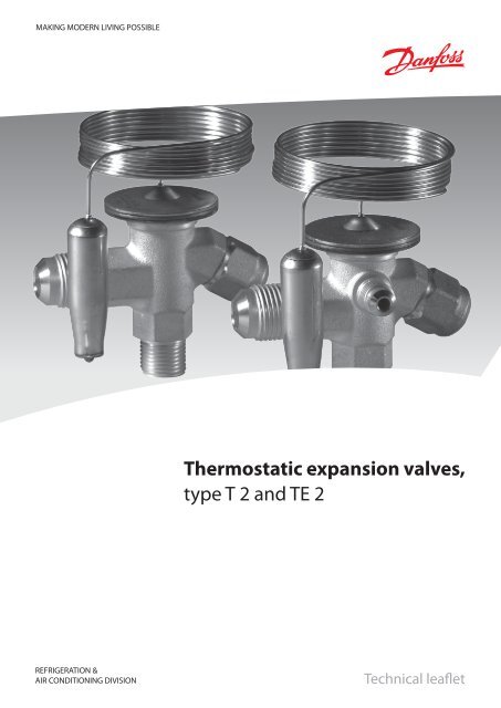
MAKING MODERN LIVING POSSIBLE<strong>Thermostatic</strong> <strong>expansion</strong> <strong>valves</strong>,<strong>type</strong> T 2 <strong>and</strong> <strong>TE</strong> 2REFRIGERATION &AIR CONDITIONING DIVISIONTechnical leaflet
Technical leaflet <strong>Thermostatic</strong> <strong>expansion</strong> <strong>valves</strong>, <strong>type</strong> T 2 <strong>and</strong> <strong>TE</strong> 2ContentsPageIntroduction. . . . . . . . . . . . . . . . . . . . . . . . . . . . . . . . . . . . . . . . . . . . . . . . . . . . . . . . . . . . . . . . . . . . . . . . . . . . . . . . . . . . . . . .3Features. . . . . . . . . . . . . . . . . . . . . . . . . . . . . . . . . . . . . . . . . . . . . . . . . . . . . . . . . . . . . . . . . . . . . . . . . . . . . . . . . . . . . . . . . . . .3Technical data . . . . . . . . . . . . . . . . . . . . . . . . . . . . . . . . . . . . . . . . . . . . . . . . . . . . . . . . . . . . . . . . . . . . . . . . . . . . . . . . . . . . . .3Superheat . . . . . . . . . . . . . . . . . . . . . . . . . . . . . . . . . . . . . . . . . . . . . . . . . . . . . . . . . . . . . . . . . . . . . . . . . . . . . . . . . .3Ordering:. . . . . . . . . . . . . . . . . . . . . . . . . . . . . . . . . . . . . . . . . . . . . . . . . . . . . . . . . . . . . . . . . . . . . . . . . . . . . . . . . . . . . . . . . . . .Components with flare × flare connection . . . . . . . . . . . . . . . . . . . . . . . . . . . . . . . . . . . . . . . . . . . . . . . . . . . . . . .4Flare connections . . . . . . . . . . . . . . . . . . . . . . . . . . . . . . . . . . . . . . . . . . . . . . . . . . . . . . . . . . . . . . . . . . . . . . . . . . .4Orifice assembly with filter . . . . . . . . . . . . . . . . . . . . . . . . . . . . . . . . . . . . . . . . . . . . . . . . . . . . . . . . . . . . . . . . . .4Components with flare × solder connection . . . . . . . . . . . . . . . . . . . . . . . . . . . . . . . . . . . . . . . . . . . . . . . . . . . . .4Solder adaptor . . . . . . . . . . . . . . . . . . . . . . . . . . . . . . . . . . . . . . . . . . . . . . . . . . . . . . . . . . . . . . . . . . . . . . . . . . . . . .5Orifice assembly with filter for solder adapter . . . . . . . . . . . . . . . . . . . . . . . . . . . . . . . . . . . . . . . . . . . . . . . .5Capacity:R22. . . . . . . . . . . . . . . . . . . . . . . . . . . . . . . . . . . . . . . . . . . . . . . . . . . . . . . . . . . . . . . . . . . . . . . . . . . . . . . . . . . . . . . . . . . . .6R407C . . . . . . . . . . . . . . . . . . . . . . . . . . . . . . . . . . . . . . . . . . . . . . . . . . . . . . . . . . . . . . . . . . . . . . . . . . . . . . . . . . . . . . . . . .7R134a . . . . . . . . . . . . . . . . . . . . . . . . . . . . . . . . . . . . . . . . . . . . . . . . . . . . . . . . . . . . . . . . . . . . . . . . . . . . . . . . . . . . . . . . . .8R404A / R507 . . . . . . . . . . . . . . . . . . . . . . . . . . . . . . . . . . . . . . . . . . . . . . . . . . . . . . . . . . . . . . . . . . . . . . . . . . . . . . . . . . .9Design - Function. . . . . . . . . . . . . . . . . . . . . . . . . . . . . . . . . . . . . . . . . . . . . . . . . . . . . . . . . . . . . . . . . . . . . . . . . . . . . . . . . 10Identification . . . . . . . . . . . . . . . . . . . . . . . . . . . . . . . . . . . . . . . . . . . . . . . . . . . . . . . . . . . . . . . . . . . . . . . . . . . . . . . . . . . . . 11Dimensions <strong>and</strong> weights. . . . . . . . . . . . . . . . . . . . . . . . . . . . . . . . . . . . . . . . . . . . . . . . . . . . . . . . . . . . . . . . . . . . . . . . . . 11 DKRCC.PD.AA0.A2.02 / 520H1659 © Danfoss A/S (AC-DSL / SKT), 12 - 2006
Technical leaflet <strong>Thermostatic</strong> <strong>expansion</strong> <strong>valves</strong>, <strong>type</strong> T 2 <strong>and</strong> <strong>TE</strong> 2Introduction<strong>Thermostatic</strong> <strong>expansion</strong> <strong>valves</strong> regulate theinjection of refrigerant liquid into evaporators.Injection is controlled by the refrigerant superheat.Therefore the <strong>valves</strong> are especially suitable forliquid injection in ”dry“ evaporators where thesuperheat at the evaporator outlet is proportionalto the evaporator load.FeaturesLarge temperature rangeEqually applicable to freezing, refrigeration<strong>and</strong> air conditioning applications.Interchangeable orifice assembly– easier stocking– easy capacity matching– better service.Rated capacities from 0.5 to 15.5 kW(0.15 to 4.5 TR) for R22.Can be supplied with MOP(Max. Operating Pressure)Protects the compressor motor againstexcessive evaporating pressure during normaloperation.Stainless steel bulbFast <strong>and</strong> easy to install.Good temperature transfer from pipe to bulb.Valves for special temperature ranges can besupplied.Technical dataMax. temperatureBulb, when valve is installed: 100°CBulb, element not mounted: 60°CMin. temperatureT 2 → <strong>TE</strong> 2: –60°CMax. test pressurePT = 38 barMax. working pressurePS/MWP = 34 barMOP-pointsRefrigerantRange N–40°C → +10°CRange NM–40°C → –5°CRange NL–40°C → –15°CRange B–60°C → –25°CMOP-point in evaporating temperature t e <strong>and</strong> evaporating pressure p e+15°C / +60°F 0°C / +32°F –10°C / +15°F –20°C / –4°FR22 100 psig/6.9 bar 60 psig/4.0 bar 35 psig/3.5 bar 20 psig/1.5 barR407C95 psig/6.6 barR134a 55 psig/5.0 bar 30 psig/3.1 bar 15 psig/2.1 barR404A/R507 120 psig/9.3 bar 75 psig/6.2 bar 50 psig/4.4 bar 30 psig/3.1 barSuperheatSS = static superheatOS = opening superheatSH = SS + OS = total superheatQ nom= rated capacityQ max= maximum capacityThe st<strong>and</strong>ard superheat setting SS is 5 K for <strong>valves</strong>without MOP <strong>and</strong> 4 K for <strong>valves</strong> with MOP.The opening superheat OS is 6 K from whenopening begins to where the valve gives its ratedcapacity Q nom.Static superheat SS can be adjusted with settingspindle.ExampleStatic superheatOpening superheatTotal superheatSS = 5 KOS = 6 KSH = 5 + 6 = 11 K© Danfoss A/S (AC-DSL / SKT), 12 - 2006 DKRCC.PD.AA0.A2.02 / 520H1659 3
Technical leaflet <strong>Thermostatic</strong> <strong>expansion</strong> <strong>valves</strong>, <strong>type</strong> T 2 <strong>and</strong> <strong>TE</strong> 2Ordering, components with flare × flare connection<strong>Thermostatic</strong> element with sensor b<strong>and</strong>, without orifice, filter cone, nutsRefrigerantValve<strong>type</strong>Pressureequalization 1 )CapillarytubeConnectionInlet × outlet 1 )Range N–40 to +10°CRange NM–40 to –5°CCode no.Range NL–40 to –15°CRange B–60 to –25°Cm in. × in. mm × mm Without MOP With MOP With MOP With MOP Without MOP With MOPR22 TX 2 Int. 1.5 3/8 × 1 /2 10 × 12 068Z3206 068Z3208 068Z3224 068Z3226 068Z3207 068Z3228<strong>TE</strong>X 2 Ext. 1.5 3/8 × 1 /2 10 × 12 068Z3209 068Z3211 068Z3225 068Z3227 068Z3210 068Z3229R407C TZ 2 Int. 1.5 3/8 × 1 /2 10 × 12 068Z3496 068Z3516<strong>TE</strong>Z 2 Ext. 1.5 3/8 × 1 /2 10 × 12 068Z3501 068Z3517R134a TN 2 Int. 1.5 3/8 × 1 /2 10 × 12 068Z3346 068Z3347 068Z3393 068Z3369R404A/R507<strong>TE</strong>N 2 Ext. 1.5 3/8 × 1 /2 10 × 12 068Z3348 068Z3349 068Z3392 068Z3370TS 2 Int. 1.5 3/8 × 1 /2 10 × 12 068Z3400 068Z3402 068Z3406 068Z3408 068Z3401 068Z3410<strong>TE</strong>S 2 Ext. 1.5 3/8 × 1 /2 10 × 12 068Z3403 068Z3405 068Z3407 068Z3409 068Z3404 068Z34111) See the section "Flare connections".Flare connectionsConnection for copper tubingwith outside diameterReducer for copper tubingwith outside diameterin. mm in. mmCode no.1/4 6 011L11013/ 8 10 011L11351/2 12 011L11031/4 6 011L1107ExampleA <strong>TE</strong> 2 thermostatic <strong>expansion</strong> valve consists oftwo elements + flare nuts if required:– 1 thermostatic element– 1 orifice assembly <strong>and</strong> flare nutsWhen ordering one thermostatic <strong>expansion</strong> valve,<strong>TE</strong>X 2 with orifice 01, five code numbers are required:– 1-off thermostatic element, 068Z3209– 1-off orifice assembly 01, 068-2010– 1-off 3 / 8 in. flare nut, 011L1135– 1-off 1 / 2 in. flare nut, 011L1103– 1-off 1 / 4 in. flare nut, 011L1101Orifice assembly with filterRange N: –40 to +10°COrifice no.Rated capacity in tons (TR)R22 R407C R134aR404AR507Rated capacity in kWR22 R407C R134aR404AR507Code no. 2 )0X 0.15 0.16 0.11 0.11 0.50 0.50 0.40 0.38 068-200200 0.30 0.30 0.25 0.21 1.0 1.1 0.90 0.70 068-200301 0.70 0.80 0.50 0.45 2.5 2.7 1.8 1.6 068-201002 1.0 1.1 0.80 0.60 3.5 3.8 2.6 2.1 068-201503 1.5 1.6 1.3 1.2 5.2 5.6 4.6 4.2 068-200604 2.3 2.5 1.9 1.7 8.0 8.6 6.7 6.0 068-200705 3.0 3.2 2.5 2.2 10.5 11.3 8.6 7.7 068-200806 4.5 4.9 3.0 2.6 15.5 16.7 10.5 9.1 068-2009The rated capacity is based on:Evaporating temperature t e= +5°Cfor range N <strong>and</strong>t e= –30°C for range BCondensing temperature t c= +32°CRefrigerant temperature aheadof valve t l= +28°CRange B: –60 to –25°COrifice no.Rated capacity in tons (TR)R22R404AR507Rated capacity in kWR22R404AR507Code no. 2 )0X 0.15 0.11 0.50 0.38 068-200200 0.20 0.21 0.70 0.70 068-200301 0.30 0.45 1.0 1.6 068-201002 0.60 0.60 2.1 2.1 068-201503 0.80 1.0 2.8 3.5 068-200604 1.2 1.4 4.2 4.9 068-200705 1.5 1.7 5.2 6.0 068-200806 2.0 1.9 7.0 6.6 068-20092)These orifice assemblies cannot be used together with solder adapters. Please see adapterinformation on next page. DKRCC.PD.AA0.A2.02 / 520H1659 © Danfoss A/S (AC-DSL / SKT), 12 - 2006
Technical leaflet <strong>Thermostatic</strong> <strong>expansion</strong> <strong>valves</strong>, <strong>type</strong> T 2 <strong>and</strong> <strong>TE</strong> 2Ordering, components with flare × solder connection<strong>Thermostatic</strong> element with sensor b<strong>and</strong>, without orifice, filter cone, nutsRefrigerantR22R407CR134aR 404A/R507Valve<strong>type</strong>Pressureequalization 3 )CapillarytubeInletFlareTX 2 Int. 1.5 3/8ConnectionOutletODF solderRange N–40 to +10°CCode no.Range NL–40 to –15°CRange B–60 to –25°Cm in. / mm in. mm Without MOP MOP +15°C Mop –10°C Without MOP MOP –20°C1/2 068Z3281 068Z3287 068Z3357 068Z3319TX 2 Int. 1.5 10 12 068Z3302 068Z3308 068Z3366 068Z3361 068Z3276<strong>TE</strong>X 2 Ext. 1.5 3/81/2 068Z3284 068Z3290 068Z3359 068Z3320<strong>TE</strong>X 2 Ext. 1.5 10 12 068Z3305 068Z3311 068Z3367 068Z3363 068Z3277TZ 2 Int. 1.5 3/81/2 068Z3329TZ 2 Int. 1.5 10 12 068Z3502 068Z3514<strong>TE</strong>Z 2 Ext. 1.5 3/81/2 068Z3446 068Z3447<strong>TE</strong>Z 2 Ext. 1.5 10 12 068Z3503 068Z3515TN 2 Int. 1.5 3/81/2 068Z3383 068Z3387TN 2 Int. 1.5 10 12 068Z3384 068Z3388<strong>TE</strong>N 2 Ext. 1.5 3/81/2 068Z3385 068Z3389<strong>TE</strong>N 2 Ext. 1.5 10 12 068Z3386 068Z3390TS 2 Int. 1.5 3/81/2 068Z3414 068Z3416 068Z3429 068Z3418 068Z3420TS 2 Int. 1.5 10 12 068Z3435 068Z3423 068Z3436 068Z3425 068Z3427<strong>TE</strong>S 2 Ext. 1.5 3/81/2 068Z3415 068Z3417 068Z3430 068Z3419 068Z3421<strong>TE</strong>S 2 Ext. 1.5 10 12 068Z3422 068Z3424 068Z3437 068Z3426 068Z34283)<strong>TE</strong> <strong>valves</strong> with inch outlet have 1 /4 inch pressure equalization. <strong>TE</strong> <strong>valves</strong> with mm outlet have 6 mm pressure equalization.Solder adaptorThe adaptor is for use with thermostatic<strong>expansion</strong> <strong>valves</strong> T 2 <strong>and</strong> <strong>TE</strong> 2 withflare × solder connections. When the adaptor isfitted correctly it meets the sealing requirementsof DIN 8964.The adaptor offers the following advantages:The orifice assembly can be replaced.The filter can be cleaned or replaced.When using the solder adapter, a special orificeassembly is required. Please use the followingtables to select both the appropriate adapter <strong>and</strong>orifice asembly.Only in this way can the sealing requirements ofDIN 8964 be fulfilled.Solder adaptor for filter drier (FSA) may not beused in the T 2 inlet.Flare connectionsSee previous page.Solder adaptor without orifice assembly <strong>and</strong> filterConnection ODF solderCode no.1/4 in. 068-20626 mm 068-20633/8 in. 068-206010 mm 068-2061Filter for solder adaptorDescriptionCode no.Filter excl. orifice assembly 068-0015Orifice assembly with filter forsolder adaptorOrifice no.Code no.0X 068-208900 068-209001 068-209102 068-209203 068-209304 068-209405 068-209506 068-2096For capacities see previous page.© Danfoss A/S (AC-DSL / SKT), 12 - 2006 DKRCC.PD.AA0.A2.02 / 520H1659 5
Technical leaflet <strong>Thermostatic</strong> <strong>expansion</strong> <strong>valves</strong>, <strong>type</strong> T 2 <strong>and</strong> <strong>TE</strong> 2CapacityCapacity in kW for range N: –40°C to +10°CValve <strong>type</strong>TX 2/<strong>TE</strong>X 2-0.15TX 2/<strong>TE</strong>X 2-0.3TX 2/<strong>TE</strong>X 2-0.7TX 2/<strong>TE</strong>X 2-1.0TX 2/<strong>TE</strong>X 2-1.5TX 2/<strong>TE</strong>X 2-2.3TX 2/<strong>TE</strong>X 2-3.0TX 2/<strong>TE</strong>X 2-4.5TX 2/<strong>TE</strong>X 2-0.15TX 2/<strong>TE</strong>X 2-0.3TX 2/<strong>TE</strong>X 2-0.7TX 2/<strong>TE</strong>X 2-1.0TX 2/<strong>TE</strong>X 2-1.5TX 2/<strong>TE</strong>X 2-2.3TX 2/<strong>TE</strong>X 2-3.0TX 2/<strong>TE</strong>X 2-4.5TX 2/<strong>TE</strong>X 2-0.15TX 2/<strong>TE</strong>X 2-0.3TX 2/<strong>TE</strong>X 2-0.7TX 2/<strong>TE</strong>X 2-1.0TX 2/<strong>TE</strong>X 2-1.5TX 2/<strong>TE</strong>X 2-2.3TX 2/<strong>TE</strong>X 2-3.0TX 2/<strong>TE</strong>X 2-4.5Orificeno.0X000102030405060X000102030405060X00010203040506Pressure drop across valve ∆p barPressure drop across valve ∆p barR222 4 6 8 10 12 14 16 2 4 6 8 10 12 14 160.370.872.23.05.48.110.212.60.370.791.62.23.95.87.49.10.481.12.84.07.210.813.616.70.470.962.02.95.17.69.611.80.400.791.41.93.45.06.47.8Evaporating temperature +10°C Evaporating temperature 0°C0.551.23.24.78.312.515.719.30.601.33.45.19.113.817.221.00.631.43.65.49.714.518.322.3Evaporating temperature –10°C0.531.12.33.35.98.711.013.50.571.22.53.66.49.512.014.70.601.22.63.86.810.112.815.6Evaporating temperature –30°C0.450.901.52.23.95.77.28.80.490.961.72.74.26.27.89.60.521.01.82.54.46.58.310.10.651.43.75.610.015.018.923.10.631.32.74.07.110.513.316.20.551.11.82.64.66.88.610.50.651.43.85.810.215.419.323.50.641.32.84.17.310.813.616.60.561.11.92.64.77.08.810.80.671.53.85.810.315.519.523.70.641.32.84.17.310.913.816.80.571.11.92.74.87.19.011.00.370.841.92.64.66.98.810.80.481.02.43.46.19.111.614.20.440.881.72.44.26.27.99.60.551.22.74.07.110.513.316.30.591.33.04.37.811.514.617.80.631.33.14.68.212.215.518.90.651.43.24.88.512.716.119.6Evaporating temperature –20°C0.501.01.92.74.87.19.011.00.541.12.02.95.27.79.811.90.571.12.23.15.58.210.312.60.591.22.33.25.88.510.813.1Evaporating temperature –40°C0.420.801.31.73.14.65.87.10.450.861.41.93.44.96.37.70.480.921.42.03.55.26.68.10.500.951.52.03.75.46.98.40.661.43.34.98.713.016.420.00.611.22.33.35.98.711.013.50.520.981.52.13.85.67.18.70.661.43.35.08.813.216.620.20.611.22.33.36.08.811.213.70.530.991.62.13.85.77.28.8Capacity in kW for range B: –60°C to –25°CValve <strong>type</strong>TX 2/<strong>TE</strong>X 2-0.2TX 2/<strong>TE</strong>X 2-0.3TX 2/<strong>TE</strong>X 2-0.6TX 2/<strong>TE</strong>X 2-0.8TX 2/<strong>TE</strong>X 2-1.2TX 2/<strong>TE</strong>X 2-1.5TX 2/<strong>TE</strong>X 2-2.0TX 2/<strong>TE</strong>X 2-0.2TX 2/<strong>TE</strong>X 2-0.3TX 2/<strong>TE</strong>X 2-0.6TX 2/<strong>TE</strong>X 2-0.8TX 2/<strong>TE</strong>X 2-1.2TX 2/<strong>TE</strong>X 2-1.5TX 2/<strong>TE</strong>X 2-2.0TX 2/<strong>TE</strong>X 2-0.2TX 2/<strong>TE</strong>X 2-0.3TX 2/<strong>TE</strong>X 2-0.6TX 2/<strong>TE</strong>X 2-0.8TX 2/<strong>TE</strong>X 2-1.2TX 2/<strong>TE</strong>X 2-1.5TX 2/<strong>TE</strong>X 2-2.0Orificeno.000102030405060001020304050600010203040506Pressure drop across valve ∆p barPressure drop across valve ∆p bar2 4 6 8 10 12 14 16 2 4 6 8 10 12 14 160.691.21.73.04.45.66.80.600.901.22.23.24.15.00.500.640.91.62.22.93.50.831.52.13.85.67.18.70.711.11.62.84.05.16.30.600.791.11.92.83.64.4Evaporating temperature –25°C0.941.72.44.36.48.19.81.01.92.64.76.98.710.71.12.02.85.07.39.311.3Evaporating temperature –40°C0.801.31.73.14.65.87.10.861.41.93.44.96.37.70.921.42.03.55.26.68.1Evaporating temperature –60°C0.660.881.22.23.14.04.90.710.951.32.33.44.35.30.751.01.42.43.64.65.61.12.02.95.27.69.611.80.951.52.13.75.46.98.40.771.01.42.53.74.85.81.12.12.95.37.89.912.10.981.52.13.85.67.18.70.791.11.42.63.84.96.01.22.13.05.37.910.012.30.991.62.13.85.77.28.80.801.11.42.63.95.06.10.661.11.52.73.95.06.10.540.741.01.82.63.44.10.791.41.93.45.06.47.80.650.921.32.33.34.25.1Evaporating temperature –30°C0.891.52.23.95.77.28.80.961.72.34.26.27.89.61.01.82.54.46.58.310.11.11.82.64.66.88.610.5Evaporating temperature –50°C0.721.01.42.63.74.75.80.781.11.52.74.05.16.20.821.21.62.94.25.46.60.851.21.73.04.45.66.91.11.92.64.77.08.810.80.871.31.73.14.55.87.11.11.92.74.87.19.011.00.881.31.73.14.65.97.2Correctionfor subcooling ∆t subNote:Insufficient subcooling can produceflash gas.The evaporator capacities used must becorrected if subcooling deviates from 4 K.The corrected capacity can be obtained bydividing the required evaporator capacity by thecorrection factor below. Selections can then bemade from the tables above.∆t u 4 K 10 K 15 K 20 K 25 K 30 K 35 K 40 K 45 K 50 KCorrection factor 1.00 1.06 1.11 1.15 1.20 1.25 1.30 1.35 1.39 1.44ExampleRefrigerant = R22Evaporator capacity Q e= 5 kWSubcooling = 10 KCorrection factor from table = 1.06Corrected capacity = 5 : 1.06 = 4.72 kW DKRCC.PD.AA0.A2.02 / 520H1659 © Danfoss A/S (AC-DSL / SKT), 12 - 2006
Technical leaflet <strong>Thermostatic</strong> <strong>expansion</strong> <strong>valves</strong>, <strong>type</strong> T 2 <strong>and</strong> <strong>TE</strong> 2CapacityCapacity in kW for range N: –40°C to +10°CValve <strong>type</strong>TZ 2/<strong>TE</strong>Z 2 - 0.16TZ 2/<strong>TE</strong>Z 2 - 0.30TZ 2/<strong>TE</strong>Z 2 - 0.80TZ 2/<strong>TE</strong>Z 2 - 1.1TZ 2/<strong>TE</strong>Z 2 - 1.6TZ 2/<strong>TE</strong>Z 2 - 2.5TZ 2/<strong>TE</strong>Z 2 - 3.2TZ 2/<strong>TE</strong>Z 2 - 4.9TZ 2/<strong>TE</strong>Z 2 - 0.16TZ 2/<strong>TE</strong>Z 2 - 0.30TZ 2/<strong>TE</strong>Z 2 - 0.80TZ 2/<strong>TE</strong>Z 2 - 1.1TZ 2/<strong>TE</strong>Z 2 - 1.6TZ 2/<strong>TE</strong>Z 2 - 2.5TZ 2/<strong>TE</strong>Z 2 - 3.2TZ 2/<strong>TE</strong>Z 2 - 4.9TZ 2/<strong>TE</strong>Z 2 - 0.16TZ 2/<strong>TE</strong>Z 2 - 0.30TZ 2/<strong>TE</strong>Z 2 - 0.80TZ 2/<strong>TE</strong>Z 2 - 1.1TZ 2/<strong>TE</strong>Z 2 - 1.6TZ 2/<strong>TE</strong>Z 2 - 2.5TZ 2/<strong>TE</strong>Z 2 - 3.2TZ 2/<strong>TE</strong>Z 2 - 4.9Orificeno.0X000102030405060X000102030405060X00010203040506Pressure drop across valve ∆p barPressure drop across valve ∆p barR407C2 4 6 8 10 12 14 16 2 4 6 8 10 12 14 160.400.902.33.15.68.410.613.10.380.821.72.34.16.07.79.50.501.12.94.17.411.114.017.20.481.02.03.05.27.89.812.00.410.811.41.93.55.16.58.0Evaporating temperature +10°C Evaporating temperature 0°C0.561.23.34.88.512.816.019.70.611.33.45.29.213.917.421.20.631.43.65.49.714.518.322.3Evaporating temperature –10°C0.541.12.33.36.08.811.113.60.571.22.53.66.49.512.014.70.601.22.63.86.810.112.815.6Evaporating temperature –30°C0.450.901.52.23.95.87.38.90.491.01.72.74.26.17.79.50.511.01.82.54.36.48.19.90.641.43.65.59.814.718.522.60.621.32.63.97.010.313.015.90.531.11.72.54.46.58.310.10.631.43.75.69.914.918.722.80.621.32.74.07.110.513.216.10.531.01.82.54.56.78.410.30.641.43.65.69.914.918.722.80.611.22.73.96.910.413.116.00.531.01.82.54.56.68.410.20.400.872.02.74.87.29.211.20.501.02.53.56.39.411.914.60.450.901.72.44.36.38.19.80.561.22.84.17.210.713.616.60.601.33.04.37.911.614.718.00.631.33.14.68.212.215.518.90.641.43.14.78.312.415.819.2Evaporating temperature –20°C0.511.01.92.74.87.29.111.10.541.12.02.95.27.79.811.90.561.12.23.15.48.110.212.50.571.22.23.15.68.210.512.7Evaporating temperature –40°C0.420.801.31.73.14.65.87.10.440.841.41.93.34.86.27.50.460.901.31.93.45.06.37.80.480.901.41.93.55.16.68.00.641.43.24.88.412.615.919.40.591.22.23.25.78.410.613.00.480.901.42.03.55.26.68.10.631.33.24.88.412.715.919.40.571.12.23.15.68.310.512.90.490.901.51.93.55.26.68.1Correctionfor subcooling ∆t subNote:Insufficient subcooling can produceflash gas.The evaporator capacities used must becorrected if subcooling deviates from 4 K.The corrected capacity can be obtained bydividing the required evaporator capacity by thecorrection factor below. Selections can then bemade from the tables above.∆t u 4 K 10 K 15 K 20 K 25 K 30 K 35 K 40 K 45 K 50 KCorrection factor 1.00 1.08 1.14 1.21 1.27 1.33 1.39 1.45 1.51 1.57© Danfoss A/S (AC-DSL / SKT), 12 - 2006 DKRCC.PD.AA0.A2.02 / 520H1659 7
Technical leaflet <strong>Thermostatic</strong> <strong>expansion</strong> <strong>valves</strong>, <strong>type</strong> T 2 <strong>and</strong> <strong>TE</strong> 2CapacityCorrectionfor subcooling ∆t subNote:Insufficient subcooling can produceflash gas.Capacity in kW for range N: –40°C to +10°CValve <strong>type</strong>TN 2/<strong>TE</strong>N 2 - 0.11TN 2/<strong>TE</strong>N 2 - 0.25TN 2/<strong>TE</strong>N 2 - 0.5TN 2/<strong>TE</strong>N 2 - 0.8TN 2/<strong>TE</strong>N 2 - 1.3TN 2/<strong>TE</strong>N 2 - 1.9TN 2/<strong>TE</strong>N 2 - 2.5TN 2/<strong>TE</strong>N 2 - 3.0TN 2/<strong>TE</strong>N 2 - 0.11TN 2/<strong>TE</strong>N 2 - 0.25TN 2/<strong>TE</strong>N 2 - 0.5TN 2/<strong>TE</strong>N 2 - 0.8TN 2/<strong>TE</strong>N 2 - 1.3TN 2/<strong>TE</strong>N 2 - 1.9TN 2/<strong>TE</strong>N 2 - 2.5TN 2/<strong>TE</strong>N 2 - 3.0TN 2/<strong>TE</strong>N 2 - 0.11TN 2/<strong>TE</strong>N 2 - 0.25TN 2/<strong>TE</strong>N 2 - 0.5TN 2/<strong>TE</strong>N 2 - 0.8TN 2/<strong>TE</strong>N 2 - 1.3TN 2/<strong>TE</strong>N 2 - 1.9TN 2/<strong>TE</strong>N 2 - 2.5TN 2/<strong>TE</strong>N 2 - 3.0Orificeno.0X000102030405060X000102030405060X00010203040506Pressure drop across valve ∆p barR134aPressure drop across valve ∆p bar2 4 6 8 10 2 4 6 8 10Evaporating temperature +10°C Evaporating temperature 0°C0.340.711.52.03.65.46.98.40.430.861.92.64.77.08.910.80.470.932.13.05.37.89.912.10.500.972.23.15.68.310.812.8Evaporating temperature –10°C0.300.591.01.42.53.64.65.70.380.701.31.83.14.65.87.10.430.771.42.03.55.16.58.00.440.811.52.13.75.46.98.4Evaporating temperature –30°C0.250.480.660.901.62.33.03.60.320.550.801.12.02.93.64.4The evaporator capacities used must becorrected if subcooling deviates from 4 K.The corrected capacity can be obtained by0.350.610.881.22.23.24.04.90.370.640.931.32.33.34.25.20.510.982.23.25.88.610.913.20.440.821.52.13.85.67.18.60.380.640.951.32.33.44.35.30.330.651.31.73.04.55.77.00.280.530.811.12.02.93.74.50.230.440.540.741.31.92.43.00.420.781.62.23.95.77.38.90.460.861.72.44.46.48.110.00.470.891.82.64.66.88.610.5Evaporating temperature –20°C0.350.621.001.42.53.64.65.60.390.691.11.52.84.05.16.20.410.721.21.62.94.35.46.6Evaporating temperature –40°C0.280.500.650.891.62.32.93.60.320.540.720.981.82.63.24.00.330.560.761.01.92.73.54.20.490.911.82.64.77.08.810.80.420.731.21.73.04.45.56.80.340.570.771.01.92.73.54.3dividing the required evaporator capacity by thecorrection factor below. Selections can then bemade from the tables above.∆t u 4 K 10 K 15 K 20 K 25 K 30 K 35 K 40 K 45 K 50 KCorrection factor 1.00 1.08 1.13 1.19 1.25 1.31 1.37 1.42 1.48 1.54 DKRCC.PD.AA0.A2.02 / 520H1659 © Danfoss A/S (AC-DSL / SKT), 12 - 2006
Technical leaflet <strong>Thermostatic</strong> <strong>expansion</strong> <strong>valves</strong>, <strong>type</strong> T 2 <strong>and</strong> <strong>TE</strong> 2CapacityCapacity in kW for range N: –40°C to +10°CValve <strong>type</strong>TS 2/<strong>TE</strong>S 2 - 0.11TS 2/<strong>TE</strong>S 2 - 0.21TS 2/<strong>TE</strong>S 2 - 0.45TS 2/<strong>TE</strong>S 2 - 0.6TS 2/<strong>TE</strong>S 2 - 1.2TS 2/<strong>TE</strong>S 2 - 1.7TS 2/<strong>TE</strong>S 2 - 2.2TS 2/<strong>TE</strong>S 2 - 2.6TS 2/<strong>TE</strong>S 2 - 0.11TS 2/<strong>TE</strong>S 2 - 0.21TS 2/<strong>TE</strong>S 2 - 0.45TS 2/<strong>TE</strong>S 2 - 0.6TS 2/<strong>TE</strong>S 2 - 1.2TS 2/<strong>TE</strong>S 2 - 1.7TS 2/<strong>TE</strong>S 2 - 2.2TS 2/<strong>TE</strong>S 2 - 2.6TS 2/<strong>TE</strong>S 2 - 0.11TS 2/<strong>TE</strong>S 2 - 0.21TS 2/<strong>TE</strong>S 2 - 0.45TS 2/<strong>TE</strong>S 2 - 0.6TS 2/<strong>TE</strong>S 2 - 1.2TS 2/<strong>TE</strong>S 2 - 1.7TS 2/<strong>TE</strong>S 2 - 2.2TS 2/<strong>TE</strong>S 2 - 2.6Orificeno.0X000102030405060X000102030405060X00010203040506Pressure drop across valve ∆p barR404A / R507Pressure drop across valve ∆p bar2 4 6 8 10 12 14 16 2 4 6 8 10 12 14 160.280.671.72.34.26.27.99.70.300.651.31.83.14.75.97.30.350.822.13.05.48.110.212.50.370.761.62.24.06.07.69.3Evaporating temperature +10°C Evaporating temperature 0°C0.400.902.33.46.09.111.414.00.420.942.43.66.49.712.214.90.430.962.53.76.610.012.515.3Evaporating temperature –10°C0.400.821.72.54.56.68.410.30.420.841.82.64.77.08.810.80.420.871.82.74.87.19.011.0Evaporating temperature –30°C0.350.671.21.62.94.35.56.70.370.701.21.73.04.55.76.90.360.701.21.73.14.55.77.00.430.962.53.76.710.012.615.30.420.871.92.74.87.29.111.10.370.701.21.73.14.55.77.00.420.932.43.76.69.812.315.10.410.851.82.74.87.19.011.00.360.691.21.73.04.55.76.90.410.902.33.66.49.612.014.70.410.831.82.64.76.98.710.70.350.671.21.62.94.45.56.80.300.681.52.13.75.57.08.60.370.801.92.64.77.18.910.90.350.701.31.93.34.96.27.60.410.872.03.05.37.910.012.20.420.902.13.15.68.310.512.90.430.922.23.25.88.610.813.20.430.932.23.35.88.610.913.3Evaporating temperature –20°C0.380.751.52.03.75.46.98.40.400.771.52.13.85.67.28.80.390.791.52.23.95.87.38.90.400.791.52.23.95.87.38.9Evaporating temperature –40°C0.320.600.921.32.33.34.35.20.330.610.961.32.43.54.45.40.330.620.971.32.43.54.55.50.330.610.961.32.43.54.45.40.430.912.23.25.78.510.813.10.390.791.52.23.95.77.28.80.320.600.941.32.33.44.45.30.410.872.13.15.68.310.412.70.380.761.52.13.85.67.18.60.320.590.911.22.23.34.25.2Capacity in kW for range B: –60°C to –25°CValve <strong>type</strong>TS 2/<strong>TE</strong>S 2 - 0.21TS 2/<strong>TE</strong>S 2 - 0.45TS 2/<strong>TE</strong>S 2 - 0.6TS 2/<strong>TE</strong>S 2 - 1.0TS 2/<strong>TE</strong>S 2 - 1.4TS 2/<strong>TE</strong>S 2 - 1.7TS 2/<strong>TE</strong>S 2 - 1.9TS 2/<strong>TE</strong>S 2 - 0.21TS 2/<strong>TE</strong>S 2 - 0.45TS 2/<strong>TE</strong>S 2 - 0.6TS 2/<strong>TE</strong>S 2 - 1.0TS 2/<strong>TE</strong>S 2 - 1.4TS 2/<strong>TE</strong>S 2 - 1.7TS 2/<strong>TE</strong>S 2 - 1.9TS 2/<strong>TE</strong>S 2 - 0.21TS 2/<strong>TE</strong>S 2 - 0.45TS 2/<strong>TE</strong>S 2 - 0.6TS 2/<strong>TE</strong>S 2 - 1.0TS 2/<strong>TE</strong>S 2 - 1.4TS 2/<strong>TE</strong>S 2 - 1.7TS 2/<strong>TE</strong>S 2 - 1.9Orificeno.000102030405060001020304050600010203040506Pressure drop across valve ∆p barPressure drop across valve ∆p bar2 4 6 8 10 12 14 16 2 4 6 8 10 12 14 160.570.981.32.43.54.45.40.671.21.73.04.45.66.80.560.851.22.13.03.94.7Evaporating temperature –25°C0.721.31.83.34.86.17.50.731.51.93.45.06.47.80.741.41.93.55.16.57.9Evaporating temperature –40°C0.600.921.32.33.34.35.20.610.961.32.43.54.45.40.620.971.32.43.54.55.5Evaporating temperature –60°C0.460.580.781.42.02.63.20.480.600.801.42.12.73.30.470.600.801.42.12.73.30.851.41.93.55.16.57.90.610.961.32.43.54.45.50.450.580.781.42.12.73.30.741.41.93.45.16.47.90.600.941.32.33.44.45.30.450.560.751.42.02.63.20.711.311.93.34.96.37.60.590.911.22.23.34.25.20.430.540.721.32.02.53.10.530.881.22.13.13.94.80.641.071.52.73.94.96.10.490.510.911.62.43.03.7Evaporating temperature –30°C0.671.21.62.94.35.56.70.701.21.73.04.55.76.90.701.21.73.14.55.77.00.701.21.73.14.55.77.0Evaporating temperature –50°C0.530.570.991.82.63.34.00.540.601.01.82.73.44.20.540.601.01.82.73.54.20.530.601.01.82.73.44.20.691.21.73.04.55.76.90.520.600.981.82.63.44.10.671.21.62.94.45.56.80.500.590.951.72.63.34.0Correctionfor subcooling ∆t subNote:Insufficient subcooling can produceflash gas.The evaporator capacities used must becorrected if subcooling deviates from 4 K.The corrected capacity can be obtained bydividing the required evaporator capacity by thecorrection factor below. Selections can then bemade from the tables above.∆t u 4 K 10 K 15 K 20 K 25 K 30 K 35 K 40 K 45 K 50 KCorrection factor 1.00 1.10 1.20 1.29 1.37 1.46 1.54 1.63 1.70 1.78© Danfoss A/S (AC-DSL / SKT), 12 - 2006 DKRCC.PD.AA0.A2.02 / 520H1659 9

![Owner's Manual (General) [pdf] - Appliance Factory Parts](https://img.yumpu.com/50830858/1/184x260/owners-manual-general-pdf-appliance-factory-parts.jpg?quality=85)