Thermostatic expansion valves, type T 2 and TE 2 - Imimg
Thermostatic expansion valves, type T 2 and TE 2 - Imimg
Thermostatic expansion valves, type T 2 and TE 2 - Imimg
- No tags were found...

Create successful ePaper yourself
Turn your PDF publications into a flip-book with our unique Google optimized e-Paper software.
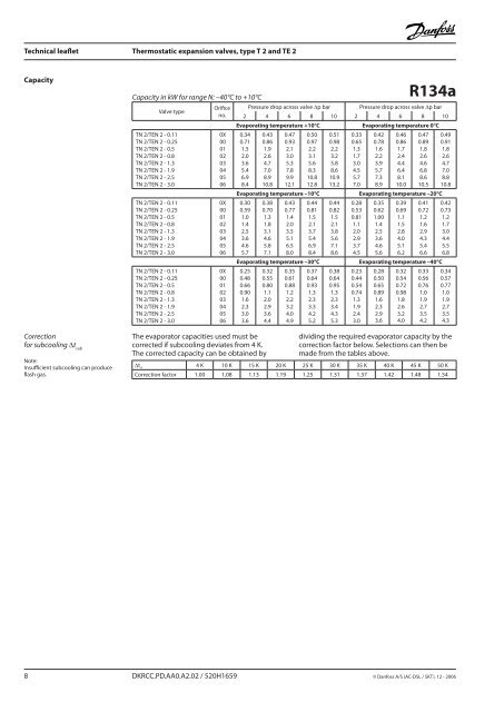
Technical leaflet <strong>Thermostatic</strong> <strong>expansion</strong> <strong>valves</strong>, <strong>type</strong> T 2 <strong>and</strong> <strong>TE</strong> 2CapacityCorrectionfor subcooling ∆t subNote:Insufficient subcooling can produceflash gas.Capacity in kW for range N: –40°C to +10°CValve <strong>type</strong>TN 2/<strong>TE</strong>N 2 - 0.11TN 2/<strong>TE</strong>N 2 - 0.25TN 2/<strong>TE</strong>N 2 - 0.5TN 2/<strong>TE</strong>N 2 - 0.8TN 2/<strong>TE</strong>N 2 - 1.3TN 2/<strong>TE</strong>N 2 - 1.9TN 2/<strong>TE</strong>N 2 - 2.5TN 2/<strong>TE</strong>N 2 - 3.0TN 2/<strong>TE</strong>N 2 - 0.11TN 2/<strong>TE</strong>N 2 - 0.25TN 2/<strong>TE</strong>N 2 - 0.5TN 2/<strong>TE</strong>N 2 - 0.8TN 2/<strong>TE</strong>N 2 - 1.3TN 2/<strong>TE</strong>N 2 - 1.9TN 2/<strong>TE</strong>N 2 - 2.5TN 2/<strong>TE</strong>N 2 - 3.0TN 2/<strong>TE</strong>N 2 - 0.11TN 2/<strong>TE</strong>N 2 - 0.25TN 2/<strong>TE</strong>N 2 - 0.5TN 2/<strong>TE</strong>N 2 - 0.8TN 2/<strong>TE</strong>N 2 - 1.3TN 2/<strong>TE</strong>N 2 - 1.9TN 2/<strong>TE</strong>N 2 - 2.5TN 2/<strong>TE</strong>N 2 - 3.0Orificeno.0X000102030405060X000102030405060X00010203040506Pressure drop across valve ∆p barR134aPressure drop across valve ∆p bar2 4 6 8 10 2 4 6 8 10Evaporating temperature +10°C Evaporating temperature 0°C0.340.711.52.03.65.46.98.40.430.861.92.64.77.08.910.80.470.932.13.05.37.89.912.10.500.972.23.15.68.310.812.8Evaporating temperature –10°C0.300.591.01.42.53.64.65.70.380.701.31.83.14.65.87.10.430.771.42.03.55.16.58.00.440.811.52.13.75.46.98.4Evaporating temperature –30°C0.250.480.660.901.62.33.03.60.320.550.801.12.02.93.64.4The evaporator capacities used must becorrected if subcooling deviates from 4 K.The corrected capacity can be obtained by0.350.610.881.22.23.24.04.90.370.640.931.32.33.34.25.20.510.982.23.25.88.610.913.20.440.821.52.13.85.67.18.60.380.640.951.32.33.44.35.30.330.651.31.73.04.55.77.00.280.530.811.12.02.93.74.50.230.440.540.741.31.92.43.00.420.781.62.23.95.77.38.90.460.861.72.44.46.48.110.00.470.891.82.64.66.88.610.5Evaporating temperature –20°C0.350.621.001.42.53.64.65.60.390.691.11.52.84.05.16.20.410.721.21.62.94.35.46.6Evaporating temperature –40°C0.280.500.650.891.62.32.93.60.320.540.720.981.82.63.24.00.330.560.761.01.92.73.54.20.490.911.82.64.77.08.810.80.420.731.21.73.04.45.56.80.340.570.771.01.92.73.54.3dividing the required evaporator capacity by thecorrection factor below. Selections can then bemade from the tables above.∆t u 4 K 10 K 15 K 20 K 25 K 30 K 35 K 40 K 45 K 50 KCorrection factor 1.00 1.08 1.13 1.19 1.25 1.31 1.37 1.42 1.48 1.54 DKRCC.PD.AA0.A2.02 / 520H1659 © Danfoss A/S (AC-DSL / SKT), 12 - 2006

![Owner's Manual (General) [pdf] - Appliance Factory Parts](https://img.yumpu.com/50830858/1/184x260/owners-manual-general-pdf-appliance-factory-parts.jpg?quality=85)