Thermostatic expansion valves, type T 2 and TE 2 - Imimg
Thermostatic expansion valves, type T 2 and TE 2 - Imimg
Thermostatic expansion valves, type T 2 and TE 2 - Imimg
- No tags were found...

Create successful ePaper yourself
Turn your PDF publications into a flip-book with our unique Google optimized e-Paper software.
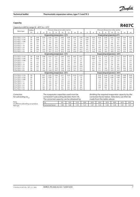
Technical leaflet <strong>Thermostatic</strong> <strong>expansion</strong> <strong>valves</strong>, <strong>type</strong> T 2 <strong>and</strong> <strong>TE</strong> 2CapacityCapacity in kW for range N: –40°C to +10°CValve <strong>type</strong>TZ 2/<strong>TE</strong>Z 2 - 0.16TZ 2/<strong>TE</strong>Z 2 - 0.30TZ 2/<strong>TE</strong>Z 2 - 0.80TZ 2/<strong>TE</strong>Z 2 - 1.1TZ 2/<strong>TE</strong>Z 2 - 1.6TZ 2/<strong>TE</strong>Z 2 - 2.5TZ 2/<strong>TE</strong>Z 2 - 3.2TZ 2/<strong>TE</strong>Z 2 - 4.9TZ 2/<strong>TE</strong>Z 2 - 0.16TZ 2/<strong>TE</strong>Z 2 - 0.30TZ 2/<strong>TE</strong>Z 2 - 0.80TZ 2/<strong>TE</strong>Z 2 - 1.1TZ 2/<strong>TE</strong>Z 2 - 1.6TZ 2/<strong>TE</strong>Z 2 - 2.5TZ 2/<strong>TE</strong>Z 2 - 3.2TZ 2/<strong>TE</strong>Z 2 - 4.9TZ 2/<strong>TE</strong>Z 2 - 0.16TZ 2/<strong>TE</strong>Z 2 - 0.30TZ 2/<strong>TE</strong>Z 2 - 0.80TZ 2/<strong>TE</strong>Z 2 - 1.1TZ 2/<strong>TE</strong>Z 2 - 1.6TZ 2/<strong>TE</strong>Z 2 - 2.5TZ 2/<strong>TE</strong>Z 2 - 3.2TZ 2/<strong>TE</strong>Z 2 - 4.9Orificeno.0X000102030405060X000102030405060X00010203040506Pressure drop across valve ∆p barPressure drop across valve ∆p barR407C2 4 6 8 10 12 14 16 2 4 6 8 10 12 14 160.400.902.33.15.68.410.613.10.380.821.72.34.16.07.79.50.501.12.94.17.411.114.017.20.481.02.03.05.27.89.812.00.410.811.41.93.55.16.58.0Evaporating temperature +10°C Evaporating temperature 0°C0.561.23.34.88.512.816.019.70.611.33.45.29.213.917.421.20.631.43.65.49.714.518.322.3Evaporating temperature –10°C0.541.12.33.36.08.811.113.60.571.22.53.66.49.512.014.70.601.22.63.86.810.112.815.6Evaporating temperature –30°C0.450.901.52.23.95.87.38.90.491.01.72.74.26.17.79.50.511.01.82.54.36.48.19.90.641.43.65.59.814.718.522.60.621.32.63.97.010.313.015.90.531.11.72.54.46.58.310.10.631.43.75.69.914.918.722.80.621.32.74.07.110.513.216.10.531.01.82.54.56.78.410.30.641.43.65.69.914.918.722.80.611.22.73.96.910.413.116.00.531.01.82.54.56.68.410.20.400.872.02.74.87.29.211.20.501.02.53.56.39.411.914.60.450.901.72.44.36.38.19.80.561.22.84.17.210.713.616.60.601.33.04.37.911.614.718.00.631.33.14.68.212.215.518.90.641.43.14.78.312.415.819.2Evaporating temperature –20°C0.511.01.92.74.87.29.111.10.541.12.02.95.27.79.811.90.561.12.23.15.48.110.212.50.571.22.23.15.68.210.512.7Evaporating temperature –40°C0.420.801.31.73.14.65.87.10.440.841.41.93.34.86.27.50.460.901.31.93.45.06.37.80.480.901.41.93.55.16.68.00.641.43.24.88.412.615.919.40.591.22.23.25.78.410.613.00.480.901.42.03.55.26.68.10.631.33.24.88.412.715.919.40.571.12.23.15.68.310.512.90.490.901.51.93.55.26.68.1Correctionfor subcooling ∆t subNote:Insufficient subcooling can produceflash gas.The evaporator capacities used must becorrected if subcooling deviates from 4 K.The corrected capacity can be obtained bydividing the required evaporator capacity by thecorrection factor below. Selections can then bemade from the tables above.∆t u 4 K 10 K 15 K 20 K 25 K 30 K 35 K 40 K 45 K 50 KCorrection factor 1.00 1.08 1.14 1.21 1.27 1.33 1.39 1.45 1.51 1.57© Danfoss A/S (AC-DSL / SKT), 12 - 2006 DKRCC.PD.AA0.A2.02 / 520H1659 7

![Owner's Manual (General) [pdf] - Appliance Factory Parts](https://img.yumpu.com/50830858/1/184x260/owners-manual-general-pdf-appliance-factory-parts.jpg?quality=85)