INSTALLATION INSTRUCTIONS Evaporator Coils - Alpine Home Air ...
INSTALLATION INSTRUCTIONS Evaporator Coils - Alpine Home Air ...
INSTALLATION INSTRUCTIONS Evaporator Coils - Alpine Home Air ...
- No tags were found...
Create successful ePaper yourself
Turn your PDF publications into a flip-book with our unique Google optimized e-Paper software.
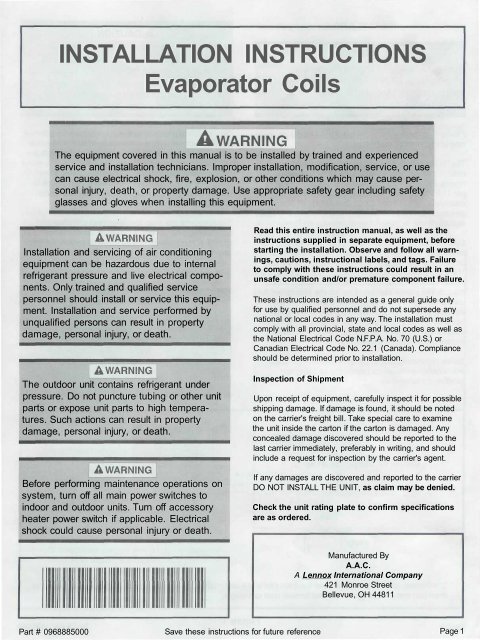
<strong>INSTALLATION</strong> <strong>INSTRUCTIONS</strong><strong>Evaporator</strong> <strong>Coils</strong>The equipment covered in this manual is to be installed by trained and experiencedservice and installation technicians. Improper installation, modification, service, or usecan cause electrical shock, fire, explosion, or other conditions which may cause personalinjury, death, or property damage. Use appropriate safety gear including safetyglasses and gloves when installing this equipment.Installation and servicing of air conditioningequipment can be hazardous due to internalrefrigerant pressure and live electrical components.Only trained and qualified servicepersonnel should install or service this equipment.Installation and service performed byunqualified persons can result in propertydamage, personal injury, or death.The outdoor unit contains refrigerant underpressure. Do not puncture tubing or other unitparts or expose unit parts to high temperatures.Such actions can result in propertydamage, personal injury, or death.Before performing maintenance operations onsystem, turn off all main power switches toindoor and outdoor units. Turn off accessoryheater power switch if applicable. Electricalshock could cause personal injury or death.Read this entire instruction manual, as well as theinstructions supplied in separate equipment, beforestarting the installation. Observe and follow all warnings,cautions, instructional labels, and tags. Failureto comply with these instructions could result in anunsafe condition and/or premature component failure.These instructions are intended as a general guide onlyfor use by qualified personnel and do not supersede anynational or local codes in any way. The installation mustcomply with all provincial, state and local codes as well asthe National Electrical Code N.F.P.A. No. 70 (U.S.) orCanadian Electrical Code No. 22.1 (Canada). Complianceshould be determined prior to installation.Inspection of ShipmentUpon receipt of equipment, carefully inspect it for possibleshipping damage. If damage is found, it should be notedon the carrier's freight bill. Take special care to examinethe unit inside the carton if the carton is damaged. Anyconcealed damage discovered should be reported to thelast carrier immediately, preferably in writing, and shouldinclude a request for inspection by the carrier's agent.If any damages are discovered and reported to the carrierDO NOT INSTALL THE UNIT, as claim may be denied.Check the unit rating plate to confirm specificationsare as ordered.Manufactured ByA.A.C.A Lennox International Company421 Monroe StreetBellevue, OH 44811Part # 0968885000 Save these instructions for future reference Page 1
<strong>INSTALLATION</strong>! A CAUTIONThis coil was manufactured containingair precharge of 20 psi.This pressurerelieved through the center of the rubberseal plugs before removing the plugs.Please read these instructions completely before beginningevaporator coil installation.The blower and duct system must be properly sized inorder to provide adequate cooling and heating performance.Select a furnace blower output of 350-450 CFMper 12,000 BTUH of cooling. All air passing over theevaporator coil must be filtered. Use return air filters ofgenerous size to avoid contaminating the coil, blower,and ductwork, or restricting necessary air flow.<strong>Evaporator</strong> coils are matched to specific condensing unitsto obtain an ARI rating. The florator orifice piston installedon each coil is chosen for the BTUH capacity of the coil.The factory installed orifice piston size is stamped on theflorator body, and is identified with a label on the front ofthe coil. The piston size must match the size called foron the refrigerant charging table found on the condensingunit. Failure to install the proper orifice pistoncan lead to poor system performance and possiblecompressor damage. A selection of replacement orificepistons is available from the distributor.Before installation, carefully wash the coil finned areaswith a coil cleaning product to remove shipping andhandling contamination.[ A CAUTIONWhen an air conditioning unit is used in conjunctionwith a furnace, the evaporator coilmust be installed in the discharge (supply) air.Do not install an evaporator coil in the returnair; excessive condensation will occur withinthe furnace.The "A" Coil drain pan is high quality engineering polymerwith a maximum service temperature of 500° F. However,adequate space must be provided between the drain panand the furnace heat exchanger. At least a 2" space isrequired for a fictionalized heat exchanger and 4" fordrum-type or oil-fired furnace exchanger (see Figure 1).Closer spacing may damage the drain pan and causeleaking.The horizontal coil drain pan is made of a high qualityengineering polymer with a maximum service temperatureof 150° F. This material has proven to be entirely satisfactoryfor use as a drain pan material with horizontal gasfurnace. The horizontal coil for bidirectional airflow, for theconvenience of refrigerant and drain line installation.|_ACAUTJON IWhen the coil is installed in an attic, above afinished ceiling, or any instance where condensateoverflow would result in propertydamage, a secondary drain pan must beprovided by the installer. The secondary drainpan must be connected to a drainage systemseparate from the primary condensate drain.Furnace Heat Exchanger* 2" minimum space required between the drain pan and a fictionalized heat exchanger or 4" minimum between thedrain pan and a drum-type or oil-fired furnace heat exchanger.Page 2Figure 1Part # 0968885000
Page 3Be sure that the coil is installed level or with a slight slopetoward the drain connection to ensure proper condensatedisposal. Long drain runs or negative air pressure conditionsin the coil housing or plenum can create the need fora vent tee in the drain line near the coil. The auxiliary drainshould be routed to empty at a location easily visible, sothat any condensate flow from that line can be seen,investigated, and the problem corrected.A brazing/soldering torch must not be used on thedrain lines closer than 6" to the drain pan. Use thetorch on fittings away from the pan and then thread theline into the pan fittings. The drain pan is equipped with aprimary (larger hole) and auxiliary pipe connection each ofwhich are 3/4" NPT. The drain lines should be no smallerthan this size. A horizontal run of condensate drain linesshould have a minimum drop of 1/4" per foot of run, so asto properly empty.Use thread sealant on drain pan fittings. Install drain linehand tight. Do not over torque.Upflow ModelsInstalling Line SetsOnly clean, dry, refrigeration-grade copper tubing shouldbe used for interconnecting refrigerant lines. Selection ofcorrect tubing size is referenced in the Product Specificationscatalog.Copper tubing should be brazed to the copper stubs at thecoil and at the condensing unit while flowing an inert gas,such as nitrogen, through the joints during heating toprevent oxide formation inside the tubing which could clogthe florator piston.To avoid damage to rubber grommets in cabinet, assemblerefrigerant lines to coil. Then remove both grommetsfrom panel by sliding over lines and away fromsource of heat. Braze refrigerant line connections and letcool before re-installing grommets.<strong>Evaporator</strong>s equipped with nonbleed expansion valvesmust be used with condensing units which either have ascroll type compressor or have hard start capability.When using an uncased coil, if the supply opening of thefurnace is larger than the drain pan in either direction, anyexisting gap must be closed off to prevent bypass of airaround the coil and drain pan. Use sheet metal angleswide enough to support the coil and attach them to theinside of the plenum.If the bottom of the duct connection extends below theapex of the coil, then the supply air duct should be ductedoff both sides of the plenum.Counterflow (Downflow) Models<strong>Air</strong> seals must be placed on the inside of the evaporator'sdrain pan to prevent water blow off (see Figure 2) in allcounterflow model installations. A kit, ACFAIRSEAL-1, isavailable from the local distributor. The kit contains four airseals, enough to complete two counterflow installations.All supply duct must be ducted below the drain pan. Thedrain connection should be kept 4" to 6" above the floorline to allow for rotation of a pipe fitting and for pitch of adrain line to a floor drain.It is not recommended that any coils be used in acounterflow model if the system is located directly overobjects which could be damaged by condensate, such asin an installation on a second floor over a finished ceiling.If such a location is unavoidable, it is suggested that awatertight, galvanized auxiliary pan at least 2" deep and atleast 2" larger in all directions than the supply plenum beinstalled beneath the supply plenum. A separate drain linefrom the auxiliary pan to an open drain should be provided.This open drain should be visible so that any watercoming from the auxiliary drain can be seen as an indicatorthat the primary drain is plugged.Figure 2
Limited WarrantyAugust 1, 1997This warranty gives you specific legal rights and you may have other rightswhich vary from state/province to state/province.Warrantor: Armstrong <strong>Air</strong> Conditioning Inc., 421 Monroe St., Bellevue, OH 44811Armstrong <strong>Air</strong> Conditioning Inc. products are available under the following names: <strong>Air</strong> Ease, Armstrong <strong>Air</strong>, American <strong>Air</strong>e, ConcordSubject to the limitations stated in this warranty, we warrant to the first buyer for use the residential heating, cooling or heat pump unit,when installed, operated and maintained as required by this warranty, to be free of defects in workmanship or material for a period of fiveyears (1 year for commercial equipment) from the time of installation. We will replace any defective component without cost or expenseto you except for the costs of delivery and labor for removal and replacement of the defective component.Warranty BeginsThe warranty period begins when the installation is complete and the product is ready to operate. You must be able to verify this datewhenever a warranty claim is made. Original bill of sale, installer's invoice or other similar document will suffice. If the beginning datecannot be verified, we will consider warranty coverage to begin six months after the date the product was shipped from our factory.Limitations on Implied WarrantiesImplied warranties of merchantability or, to the extent applicable, fitness for a particular purpose are limited to five years, the sameduration as the basic limited written warranty provided herein. Some states/provinces do not allow limitations on how long an impliedwarranty of merchantability or fitness lasts, so the above limitations or exclusions may not apply to you.Only WarrantyThis written Limited Warranty is the only warranty made by the warrantor; this warranty is in lieu of and excludes all other warranties,express or implied. The warrantor does not authorize any person to provide any other warranty or to assume for it any further obligationin connection with the warranted product.What is NOT Covered1. Cabinets or cabinet pieces.2. Normal maintenance items such as filters, fan belts, fuses or other consumable items.3. Damage caused by misuse, failure to maintain properly, accidents or acts of God.4. External wiring, piping, venting or attachment of accessory products not integral to our product, including without limitation,humidifier, air cleaner, vent damper, thermostat or other mechanical devices not manufactured by the warrantor.5. Products that have been operated in a corrosive atmosphere where a concentration of acids, halogenated hydrocarbons orother corrosive elements causes deterioration to metal surfaces or integral components. NOTE: Operation in a corrosiveatmosphere is considered abuse and voids this warranty.6. Products that have NOT been installed in accordance with our published installation instructions, applicable local, state/provincial or national codes, ACCA published standards.7. Products that have NOT been installed by competent, qualified installers.8. Products that have been moved from their original place of installation.Warranty on Replacement ComponentsAny replacement component furnished by us will assume the remaining (unused) portion of the Limited Warranty.Consequential DamagesThe warrantor shall not be responsible for any consequential damages caused by any defect in the product. Some state/provinces do notallow the exclusion or limitations of incidental or consequential damages, so the above limitation or exclusion may not apply to you.NOTE: After the first year, in the event that a gas or oil heat exchanger is no longer being manufactured by the warrantor, the warrantorwill allow a credit equal to the then current wholesale price of an equivalent heat exchanger towards the purchase of a new Armstrong gasor oil furnace.This product must be installed, used and cared for in accordance with the instruction manual. You are responsible for required periodicmaintenance or service, such as changing or cleaning of air filters and lubrication or cleaning of components. Failure to properly install,operate or maintain your unit voids this warranty.Owner RecordModel # Serial # Installation DateINSTALLED BY:DealerAddressTelephone # License #



![Owner's Manual (General) [pdf] - Appliance Factory Parts](https://img.yumpu.com/50830858/1/184x260/owners-manual-general-pdf-appliance-factory-parts.jpg?quality=85)
