Direct Vent Tankless Water Heater - Alpine Home Air Products
Direct Vent Tankless Water Heater - Alpine Home Air Products
Direct Vent Tankless Water Heater - Alpine Home Air Products

Create successful ePaper yourself
Turn your PDF publications into a flip-book with our unique Google optimized e-Paper software.
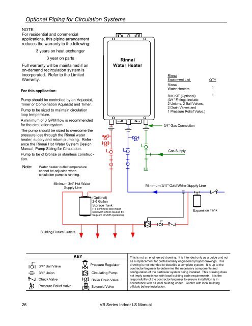
Optional Piping for Circulation SystemsNOTE:For residential and commercialapplications, this piping arrangementreduces the warranty to the following:3 years on heat exchangerFor this application:3 year on partsFull warranty will be maintained if anon-demand recirculation system isincorporated. Refer to the LimitedWarranty.Pump should be controlled by an Aquastat,Timer or Combination Aquastat and Timer.Pump to be sized to maintain circulationloop temperature.Rinnai<strong>Water</strong> <strong>Heater</strong>RinnaiEquipment ListRinnai<strong>Water</strong> <strong>Heater</strong>sRIK-KIT (Optional)(3/4" Fittings Include:2 Unions, 2 Ball Valves,2Drain Valvesand1 Pressure Relief Valve.)QTY11A minimum of 3 GPM flow is recommendedfor the circulation system.The pump should be sized to overcome thepressure loss through the Rinnai waterheater, supply and return plumbing. Refer -ence the Rinnai Hot <strong>Water</strong> System DesignManual, Pump Sizing for Circulation.Pump to be of bronze or stainless construc -tion.3/4" Gas ConnectionGas SupplyNote:<strong>Water</strong> heater outlet temperaturecannot be adjusted whencirculationpumpisrunning.Minimum 3/4" Hot <strong>Water</strong>Supply LineMinimum 3/4“ Cold <strong>Water</strong> Supply Line(Optional)2-6 GallonStorage Tank(To eliminate cold watersandwich effect caused byfrequent On/Off operation)Expansion TankBuilding Fixture Outlets3/4" Ball Valve3/4" UnionCheck ValvePressure Relief ValveKEYSPressure RegulatorCirculating PumpBoiler Drain ValveSolenoid ValveThis is not an engineered drawing. It is intended only as a guide and notas a replacement for professionally engineered project drawings. Thisdrawing is not intended to describe a complete system. It is up to thecontractor/engineer to determine the necessary components andconfiguration of the particular system being installed. This drawing doesnot imply compliance with local building code requirements. It is theresponsibility of the contractor/engineer to ensure installation is inaccordance with all local building codes. Confer with local buildingofficials before installation.26 VB Series Indoor LS Manual

![Owner's Manual (General) [pdf] - Appliance Factory Parts](https://img.yumpu.com/50830858/1/184x260/owners-manual-general-pdf-appliance-factory-parts.jpg?quality=85)