Direct Vent Tankless Water Heater - Alpine Home Air Products
Direct Vent Tankless Water Heater - Alpine Home Air Products
Direct Vent Tankless Water Heater - Alpine Home Air Products

You also want an ePaper? Increase the reach of your titles
YUMPU automatically turns print PDFs into web optimized ePapers that Google loves.
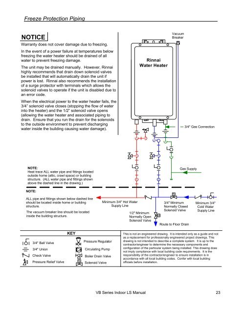
Freeze Protection PipingNOTICEWarranty does not cover damage due to freezing.In the event of a power failure at temperatures belowfreezing the water heater should be drained of allwater to prevent freezing damage.The unit may be drained manually. However, Rinnaihighly recommends that drain down solenoid valvesbe installed that will automatically drain the unit ifpower is lost. Rinnai also recommends the installationof a surge protector with terminals which allows thesolenoid valves to operate if the unit is disabled due toan error code.When the electrical power to the water heater fails, the3/4” solenoid valve closes (stopping the flow of waterinto the heater) and the 1/2” solenoid valve opens(allowing the water heater and associated piping todrain. Ensure that you run the drain for the solenoidsto the outside environment to prevent dischargingwater inside the building causing water damage).Rinnai<strong>Water</strong> <strong>Heater</strong>VacuumBreaker3/4" Gas ConnectionNOTE:Heat trace ALL water pipe and fittings locatedoutside home (attic, crawl space) or buildingstructure. (ALL water pipe and fittings shownabove the dashed line in the drawing.)Gas SupplyNOTE:ALL pipe and fittings shown below dashed lineshould be located inside home or buildingstructure.The vacuum breaker line should be locatedinside the building structure.Minimum 3/4" Hot <strong>Water</strong>Supply Line1/2" MinimumNormally OpenSolenoid ValveSS3/4" MinimumNormally ClosedSolenoid ValveRoute to Floor DrainMinimum 3/4"Cold <strong>Water</strong>Supply Line3/4" Ball Valve3/4" UnionCheck ValvePressure Relief ValveKEYSPressure RegulatorCirculating PumpBoiler Drain ValveSolenoid ValveThis is not an engineered drawing. It is intended only as a guide and notas a replacement for professionally engineered project drawings. Thisdrawing is not intended to describe a complete system. It is up to thecontractor/engineer to determine the necessary components andconfiguration of the particular system being installed. This drawing doesnot imply compliance with local building code requirements. It is theresponsibility of the contractor/engineer to ensure installation is inaccordance with all local building codes. Confer with local buildingofficials before installation.VB Series Indoor LS Manual 23

![Owner's Manual (General) [pdf] - Appliance Factory Parts](https://img.yumpu.com/50830858/1/184x260/owners-manual-general-pdf-appliance-factory-parts.jpg?quality=85)