Atmel Segment LCD1 Xplained Pro (USER GUIDE) - Atmel Store
Atmel Segment LCD1 Xplained Pro (USER GUIDE) - Atmel Store
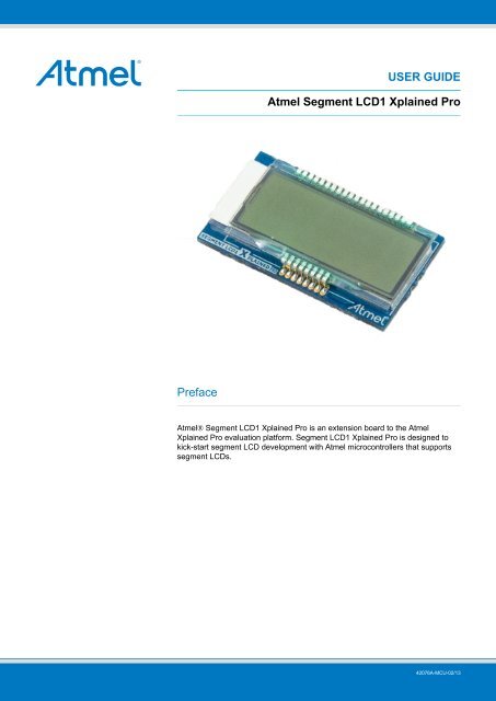
Atmel Segment LCD1 Xplained Pro (USER GUIDE) - Atmel Store

You also want an ePaper? Increase the reach of your titles
YUMPU automatically turns print PDFs into web optimized ePapers that Google loves.
Description Function Pin Pin Function Description<strong>Segment</strong> 12 SEG12 17 18 SEG13 <strong>Segment</strong> 13<strong>Segment</strong> 14 SEG14 19 20 SEG15 <strong>Segment</strong> 15<strong>Segment</strong> 16 SEG16 21 22 SEG17 <strong>Segment</strong> 17<strong>Segment</strong> 18 SEG18 23 24 SEG19 <strong>Segment</strong> 19<strong>Segment</strong> 20 SEG20 25 26 SEG21 <strong>Segment</strong> 21<strong>Segment</strong> 22 SEG22 27 28 SEG23 <strong>Segment</strong> 23<strong>Segment</strong> 24 SEG24 29 30 SEG25 <strong>Segment</strong> 25<strong>Segment</strong> 26 SEG26 31 32 SEG27 <strong>Segment</strong> 27<strong>Segment</strong> 28 SEG28 33 34 SEG29 <strong>Segment</strong> 29<strong>Segment</strong> 30 SEG30 35 36 SEG31 <strong>Segment</strong> 31<strong>Segment</strong> 32 SEG32 37 38 SEG33 <strong>Segment</strong> 33<strong>Segment</strong> 34 SEG34 39 40 SEG35 <strong>Segment</strong> 35<strong>Segment</strong> 36 SEG36 41 42 SEG37 <strong>Segment</strong> 37<strong>Segment</strong> 38 SEG38 43 44 SEG39 <strong>Segment</strong> 39Not Connected NC 45 46 NC Not ConnectedBacklight Anode Backlight V+ 47 48 Backlight V- Backlight CathodeBacklight ControlBacklightCTRLGround GND 5149 50 ID <strong>Xplained</strong> <strong>Pro</strong> ID line<strong>Atmel</strong> <strong>Segment</strong> <strong>LCD1</strong> <strong>Xplained</strong> <strong>Pro</strong> [<strong>USER</strong> <strong>GUIDE</strong>]42076A-MCU-02/137
4. Hardware user guide4.1 Headers and connectors4.1.1 <strong>Segment</strong> <strong>LCD1</strong> <strong>Xplained</strong> <strong>Pro</strong> extension connector<strong>Segment</strong> <strong>LCD1</strong> <strong>Xplained</strong> <strong>Pro</strong> implements one segment LCD extension connector which makes it possible toconnect the board to any <strong>Xplained</strong> <strong>Pro</strong> MCU board with segment LCD support. <strong>Segment</strong> <strong>LCD1</strong> <strong>Xplained</strong> <strong>Pro</strong>requires 4 common terminals and segment terminal 0 through 23 to control all segments. The complete pinmappingfor the connector is described in Table 4.1, “<strong>Segment</strong> <strong>LCD1</strong> <strong>Xplained</strong> <strong>Pro</strong> Extension Connector”.Table 4.1. <strong>Segment</strong> <strong>LCD1</strong> <strong>Xplained</strong> <strong>Pro</strong> Extension ConnectorDescription Function Pin Pin Function DescriptionCommon terminal 3 COM3 1 2 COM2 Common terminal 2Common terminal 1 COM1 3 4 COM0 Common terminal 0<strong>Segment</strong> 0 SEG0 5 6 SEG1 <strong>Segment</strong> 1<strong>Segment</strong> 2 SEG2 7 8 SEG3 <strong>Segment</strong> 3<strong>Segment</strong> 4 SEG4 9 10 SEG5 <strong>Segment</strong> 5<strong>Segment</strong> 6 SEG6 11 12 SEG7 <strong>Segment</strong> 7<strong>Segment</strong> 8 SEG8 13 14 SEG9 <strong>Segment</strong> 9<strong>Segment</strong> 10 SEG10 15 16 SEG11 <strong>Segment</strong> 11<strong>Segment</strong> 12 SEG12 17 18 SEG13 <strong>Segment</strong> 13<strong>Segment</strong> 14 SEG14 19 20 SEG15 <strong>Segment</strong> 15<strong>Segment</strong> 16 SEG16 21 22 SEG17 <strong>Segment</strong> 17<strong>Segment</strong> 18 SEG18 23 24 SEG19 <strong>Segment</strong> 19<strong>Segment</strong> 20 SEG20 25 26 SEG21 <strong>Segment</strong> 21<strong>Segment</strong> 22 SEG22 27 28 SEG23 <strong>Segment</strong> 23NC 29 30 NCNC 31 32 NCNC 33 34 NCNC 35 36 NCNC 37 38 NCNC 39 40 NCNC 41 42 NCNC 43 44 NCNC 45 46 NCBacklight Anode Backlight V+ 47 48 Backlight V- Backlight CathodeBacklight ControlBacklightCTRLGround GND 5149 50 ID <strong>Xplained</strong> <strong>Pro</strong> ID line4.2 <strong>Segment</strong> LCD display<strong>Segment</strong> <strong>LCD1</strong> <strong>Xplained</strong> <strong>Pro</strong> features an LCD module with 4 common and 24 segment terminals. These 96segments form several symbols and five 14-segment characters. The LCD module runs at 1/4 duty cycle and1/3 bias and has yellow-green backlighting.4.2.1 <strong>Segment</strong>sFigure 4.1, “YMCC42412AAAFDCL segments” and Table 4.2, “YMCC42412AAAFDCL segments” shows therelation between the common terminals, segment terminals and the segments on the display.<strong>Atmel</strong> <strong>Segment</strong> <strong>LCD1</strong> <strong>Xplained</strong> <strong>Pro</strong> [<strong>USER</strong> <strong>GUIDE</strong>]42076A-MCU-02/138
Figure 4.1. YMCC42412AAAFDCL segmentsTable 4.2. YMCC42412AAAFDCL segments4.2.2 BacklightCOM0 COM1 COM2 COM3 CommentsSEG0 G1 G2 G4 G3SEG1 G0 G6 G7 G5SEG2 E7 E5 E3 E1SEG3 E6 E4 E2 E0SEG4 A0-h A0-i A0-k A0-nSEG5 B3 A0-f A0-e A0-dSEG6 A0-a A0-b A0-c B4SEG7 A0-g A0-j A0-l A0-mSEG8 A1-h A1-i A1-k A1-nSEG9 B2 A1-f A1-e A1-dSEG10 A1-a A1-b A1-c B5SEG11 A1-g A1-j A1-l A1-mSEG12 A2-h A2-i A2-k A2-nSEG13 B1 A2-f A2-e A2-dSEG14 A2-a A2-b A2-c B6SEG15 A2-g A2-j A2-l A2-mSEG16 A3-h A3-i A3-k A3-nSEG17 B0 A3-f A3-e A3-dSEG18 A3-a A3-b A3-c B7SEG19 A3-g A3-j A3-l A3-mSEG20 A4-h A4-i A4-k A4-nSEG21 B8 A4-f A4-e A4-dSEG22 A4-a A4-b A4-c B9SEG23 A4-g A4-j A4-l A4-m<strong>Atmel</strong> logo, 4 stage battery-, Dot-point-, usbandplay indicator4 stage wireless-, AM-, PM- Volt- and milli voltindicator1st 14-segment character.2nd 14-segment character3rd 14-segment character4th 14-segment character.5th 14-segment character. Celsius andFahrenheit indicator.The segment LCD’s backlight is disabled by default and can be enabled by driving the BACKLIGHT CTRL pinhigh. A FET drives the backlight. A PWM signal can be used to control the backlight intensity.<strong>Atmel</strong> <strong>Segment</strong> <strong>LCD1</strong> <strong>Xplained</strong> <strong>Pro</strong> [<strong>USER</strong> <strong>GUIDE</strong>]42076A-MCU-02/139
5. Hardware revision history and known issues5.1 Identifying product ID and revisionThe revision and product identifier of <strong>Xplained</strong> <strong>Pro</strong> boards can be found in two ways, through <strong>Atmel</strong> Studio orby looking at the sticker on the bottom side of the PCB.By connecting a <strong>Xplained</strong> <strong>Pro</strong> MCU board to a computer with <strong>Atmel</strong> Studio running, an information window willpop up. The first 6 digits of the serial number, which is listed under kit details, contain the product identifier andrevision. Information about connected <strong>Xplained</strong> <strong>Pro</strong> extension boards will also appear in the <strong>Atmel</strong> Kits window.The same information can be found on the sticker on the bottom side of the PCB. Most kits will print the identifierand revision in plain text as A09-nnnn\rr where nnnn is the identifier and rr is the revision. Boards with limitedspace have a sticker with only a QR-code which contains a serial number string.The serial number string has the following format:"nnnnrrssssssssss"n = product identifierr = revisions = serial numberThe kit identifier for <strong>Segment</strong> <strong>LCD1</strong> <strong>Xplained</strong> <strong>Pro</strong> is 1774.5.2 Revision 2Revision 2 of <strong>Segment</strong> <strong>LCD1</strong> <strong>Xplained</strong> <strong>Pro</strong> is the initial released version. There are no known issues<strong>Atmel</strong> <strong>Segment</strong> <strong>LCD1</strong> <strong>Xplained</strong> <strong>Pro</strong> [<strong>USER</strong> <strong>GUIDE</strong>]42076A-MCU-02/1310
6. Document revision historyDoc. Rev. Date CommentA 25/02/2013 First release<strong>Atmel</strong> <strong>Segment</strong> <strong>LCD1</strong> <strong>Xplained</strong> <strong>Pro</strong> [<strong>USER</strong> <strong>GUIDE</strong>]42076A-MCU-02/1311
7. Evaluation board/kit important notice7.1 Evaluation board/kit important noticeThis evaluation board/kit is intended for use for FURTHER ENGINEERING, DEVELOPMENT, DEMONS-TRATION, OR EVALUATION PURPOSES ONLY. It is not a finished product and may not (yet) comply withsome or any technical or legal requirements that are applicable to finished products, including, without limitation,directives regarding electromagnetic compatibility, recycling (WEEE), FCC, CE or UL (except as may beotherwise noted on the board/kit). <strong>Atmel</strong> supplied this board/kit "AS IS," without any warranties, with all faults,at the buyer's and further users' sole risk. The user assumes all responsibility and liability for proper and safehandling of the goods. Further, the user indemnifies <strong>Atmel</strong> from all claims arising from the handling or use ofthe goods. Due to the open construction of the product, it is the user's responsibility to take any and all appropriateprecautions with regard to electrostatic discharge and any other technical or legal concerns.EXCEPT TO THE EXTENT OF THE INDEMNITY SET FORTH ABOVE, NEITHER <strong>USER</strong> NOR ATMEL SHALLBE LIABLE TO EACH OTHER FOR ANY INDIRECT, SPECIAL, INCIDENTAL, OR CONSEQUENTIAL DAM-AGES.No license is granted under any patent right or other intellectual property right of <strong>Atmel</strong> covering or relating toany machine, process, or combination in which such <strong>Atmel</strong> products or services might be or are used.Mailing Address: <strong>Atmel</strong> Corporation, 1600 Technology Drive, San Jose, CA 95110<strong>Atmel</strong> <strong>Segment</strong> <strong>LCD1</strong> <strong>Xplained</strong> <strong>Pro</strong> [<strong>USER</strong> <strong>GUIDE</strong>]42076A-MCU-02/1312
<strong>Atmel</strong> Corporation 1600 Technology Drive, San Jose, CA 95110 USA T: (+1)(408) 441.0311 F: (+1)(408) 436.4200 | www.atmel.com© 2013 <strong>Atmel</strong> Corporation. All rights reserved. / Rev.: 42076A-MCU-02/13<strong>Atmel</strong>®, <strong>Atmel</strong> logo and combinations thereof, , Enabling Unlimited Possibilities®, and others are registered trademarks or trademarks of <strong>Atmel</strong>Corporation or its subsidiaries. Other terms and product names may be trademarks of others.Disclaimer: The information in this document is provided in connection with <strong>Atmel</strong> products. No license, express or implied, by estoppel or otherwise, to any intellectual property right is grantedby this document or in connection with the sale of <strong>Atmel</strong> products. EXCEPT AS SET FORTH IN THE ATMEL TERMS AND CONDITIONS OF SALES LOCATED ON THE ATMEL WEBSITE,ATMEL ASSUMES NO LIABILITY WHATSOEVER AND DISCLAIMS ANY EXPRESS, IMPLIED OR STATUTORY WARRANTY RELATING TO ITS PRODUCTS INCLUDING, BUT NOTLIMITED TO, THE IMPLIED WARRANTY OF MERCHANTABILITY, FITNESS FOR A PARTICULAR PURPOSE, OR NON-INFRINGEMENT. IN NO EVENT SHALL ATMEL BE LIABLE FORANY DIRECT, INDIRECT, CONSEQUENTIAL, PUNITIVE, SPECIAL OR INCIDENTAL DAMAGES (INCLUDING, WITHOUT LIMITATION, DAMAGES FOR LOSS AND PROFITS, BUSINESSINTERRUPTION, OR LOSS OF INFORMATION) ARISING OUT OF THE USE OR INABILITY TO USE THIS DOCUMENT, EVEN IF ATMEL HAS BEEN ADVISED OF THE POSSIBILITY OFSUCH DAMAGES. <strong>Atmel</strong> makes no representations or warranties with respect to the accuracy or completeness of the contents of this document and reserves the right to make changes tospecifications and products descriptions at any time without notice. <strong>Atmel</strong> does not make any commitment to update the information contained herein. Unless specifically provided otherwise,<strong>Atmel</strong> products are not suitable for, and shall not be used in, automotive applications. <strong>Atmel</strong> products are not intended, authorized, or warranted for use as components in applications intendedto support or sustain life.