Configuration Handbook - Kamami.pl
Configuration Handbook - Kamami.pl
Configuration Handbook - Kamami.pl

Create successful ePaper yourself
Turn your PDF publications into a flip-book with our unique Google optimized e-Paper software.
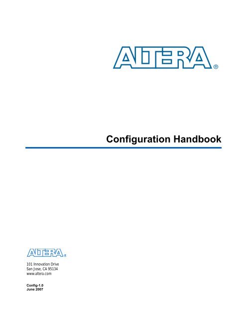
<strong>Configuration</strong> <strong>Handbook</strong>Preliminary Information101 Innovation DriveSan Jose, CA 95134www.altera.comConfig-1.0June 2007
Copyright © 2007 Altera Corporation. All rights reserved. Altera, The Programmable Solutions Company, the stylized Altera logo, specific device designations,and all other words and logos that are identified as trademarks and/or service marks are, unless noted otherwise, the trademarks andservice marks of Altera Corporation in the U.S. and other countries. All other product or service names are the property of their respective holders. Alteraproducts are protected under numerous U.S. and foreign patents and pending ap<strong>pl</strong>ications, maskwork rights, and copyrights. Altera warrantsperformance of its semiconductor products to current specifications in accordance with Altera's standard warranty, but reserves the right to makechanges to any products and services at any time without notice. Altera assumes no responsibility or liability arising out of the ap<strong>pl</strong>icationor use of any information, product, or service described herein except as expressly agreed to in writing by AlteraCorporation. Altera customers are advised to obtain the latest version of device specifications before relying on any published informationand before <strong>pl</strong>acing orders for products or services.ii Altera CorporationPreliminary
ContentsVolume I........................................................................................................................................................................................................................4Section I. Altera FPGAs..............................................................................................................................................................................................5Configuring Altera FPGAs........................................................................................................................................................................................6Configuring Stratix III Devices..................................................................................................................................................................................14Configuring Stratix II & Stratix II GX Devices...........................................................................................................................................................98Configuring Stratix & Stratix GX Devices.................................................................................................................................................................204Configuring Cyclone II Devices................................................................................................................................................................................264Configuring Cyclone FPGAs....................................................................................................................................................................................336Configuring APEX II Devices...................................................................................................................................................................................388Configuring APEX 20KE & APEX 20KC Devices.....................................................................................................................................................456Configuring Mercury, APEX 20K [2.5 V], ACEX 1K & FLEX 10K Devices...............................................................................................................526Volume II.......................................................................................................................................................................................................................596Section I. FPGA <strong>Configuration</strong> Devices......................................................................................................................................................................597Altera <strong>Configuration</strong> Devices....................................................................................................................................................................................598Enhanced <strong>Configuration</strong> Devices [EPC4, EPC8 & EPC16] Data Sheet..................................................................................................................606Altera Enhanced <strong>Configuration</strong> Devices..................................................................................................................................................................644Serial <strong>Configuration</strong> Devices [EPCS1, EPCS4, EPCS16 & EPCS64] Data Sheet..................................................................................................666<strong>Configuration</strong> Devices for SRAM-Based LUT Devices Data Sheet.........................................................................................................................708Section II. Software Settings.......................................................................................................................................................................................742Device <strong>Configuration</strong> Options..................................................................................................................................................................................743<strong>Configuration</strong> File Formats.......................................................................................................................................................................................753Section III. Advanced <strong>Configuration</strong> Schemes............................................................................................................................................................761Configuring Mixed Altera FPGA Chains...................................................................................................................................................................762Combining Different <strong>Configuration</strong> Schemes...........................................................................................................................................................766Using Flash Memory to Configure FPGAs...............................................................................................................................................................774Section IV. Board Layout Tips & Debugging Techniques.........................................................................................................................................788Debugging <strong>Configuration</strong> Problems.........................................................................................................................................................................789Altera Corporationiii
<strong>Configuration</strong> <strong>Handbook</strong>, Volume IPreliminary Information101 Innovation DriveSan Jose, CA 95134www.altera.com
Altera FPGAsPreliminary Information101 Innovation DriveSan Jose, CA 95134www.altera.com
1. Configuring Altera FPGAsCF51001-2.1IntroductionStratix ® series, Cyclone series, APEX II, APEX 20K (includingAPEX 20KE and APEX 20KC), Mercury, ACEX ® 1K, FLEX ® 10K(including FLEX 10KE and FLEX 10KA), and FLEX 6000 devices can beconfigured using one of seven configuration schemes. Table 1–1 showswhich device families support which configuration schemes.Table 1–1. <strong>Configuration</strong> Scheme Device Family SupportDevice Family<strong>Configuration</strong>SchemeStratix IIStratix, Stratix GXCyclone IICycloneAPEX IIAPEX 20K, APEX 20KE,APEX 20KCMercuryACEX 1KFLEX 10K, FLEX 10KE,FLEX 10KAFLEX 6000Passive Serial (PS) v v v v v v v v v vActive Serial (AS) v v vFast Passive Parallel(FPP)v v vPassive ParallelSynchronous (PPS)Passive ParallelAsynchronous (PPA)Passive SerialAsynchronous (PSA)Joint Test ActionGroup (JTAG)v v v vv v v v v v vv v v v v v v v v (1)Note to Table 1–1:(1) Although you cannot configure FLEX 6000 devices through the JTAG pins, you can perform JTAG boundary-scantesting.vAltera Corporation 1–1August 2005
IntroductionAll configuration schemes use either an intelligent host or a configurationdevice(s) (Table 1–2).Table 1–2. <strong>Configuration</strong> Schemes<strong>Configuration</strong> SchemeTypical UsePassive Serial (PS)<strong>Configuration</strong> with the enhanced configuration devices (EPC16, EPC8,and EPC4), EPC2, EPC1, EPC1441 configuration devices, serialsynchronous microprocessor interface, the USB Blaster USB PortDownload Cable, MasterBlaster TM communications cable, ByteBlaster TM IIparallel download cable or ByteBlasterMV TM parallel port download cable.Active Serial (AS)<strong>Configuration</strong> with the serial configuration devices (EPCS1 and EPCS4).Passive Parallel Synchronous (PPS) <strong>Configuration</strong> with a parallel synchronous microprocessor interface.Fast Passive Parallel (FPP) <strong>Configuration</strong> with an enhanced configuration device or parallelsynchronous microprocessor interface where 8 bits of configuration dataare loaded on every clock cycle. Eight times faster than PPS.Passive Parallel Asynchronous(PPA)Passive Serial Asynchronous (PSA)<strong>Configuration</strong> with a parallel asynchronous microprocessor interface. Inthis scheme, the microprocessor treats the target device as memory.<strong>Configuration</strong> with a serial asynchronous microprocessor interface.Joint Test Action Group (JTAG) <strong>Configuration</strong> through the IEEE Std. 1149.1 (JTAG) pins. (1)The following chapters discuss how to configure one or more Stratixseries, Cyclone series, APEX II, APEX 20K (including APEX 20KE andAPEX 20KC), Mercury, ACEX 1K, FLEX 10K (including FLEX 10KE andFLEX 10KA), and FLEX 6000 devices. The following chapters should beused in conjunction with the following documents:■■■■■■■■■■■■■Stratix II Device <strong>Handbook</strong>Stratix Device <strong>Handbook</strong>Stratix GX FPGA Family Data SheetCyclone II Device <strong>Handbook</strong>Cyclone Device <strong>Handbook</strong>APEX II Programmable Logic Device Family Data SheetAPEX 20K Programmable Logic Device Family Data SheetAPEX 20KC Programmable Logic Device Data SheetMercury Programmable Logic Device Family Data SheetACEX 1K Programmable Logic Device Family Data SheetFLEX 10K Embedded Programmable Logic Family Data SheetFLEX 10KE Embedded Programmable Logic Family Data SheetFLEX 6000 Programmable Logic Device Family Data SheetVolume I covers how to configure Altera FPGAs, where each chaptercovers a different device family. Each subsection describes how toconfigure the devices with the following configuration schemes:1–2 Altera Corporation<strong>Configuration</strong> <strong>Handbook</strong>, Volume 1 August 2005
Configuring Altera FPGAs■■■■■■■PS <strong>Configuration</strong>● Using a <strong>Configuration</strong> Device● Using a Microprocessor● Using a Download CableAS <strong>Configuration</strong> (Stratix II FPGAs and the Cyclone Series Only)FPP <strong>Configuration</strong> (Stratix Series and APEX II Devices Only)● Using an enhanced <strong>Configuration</strong> Device● Using a MicroprocessorPPS <strong>Configuration</strong> (APEX 20K, Mercury, ACEX 1K, and FLEX 10KDevices Only)PPA <strong>Configuration</strong> (Stratix Series, APEX II, APEX 20K, Mercury,ACEX 1K, and FLEX 10K Devices Only)PSA <strong>Configuration</strong> (FLEX 6000 Devices Only)JTAG Programming and <strong>Configuration</strong> (Stratix Series,Cyclone Series, APEX II, APEX 20K, Mercury, ACEX 1K, andFLEX 10K Devices Only)Volume II contains information that is relevant for all Altera FPGAsdiscussed in this handbook. Information about configuration devices andcombining different Altera device families in the same configurationchain can be found in this volume.Device<strong>Configuration</strong>Overview forPassiveSchemesDuring device operation, Altera FPGAs store configuration data in SRAMcells. Because SRAM memory is volatile, the SRAM cells must be loadedwith configuration data each time the device powers up. After the deviceis configured, its registers and I/O pins must be initialized. Afterinitialization, the device enters user mode for in-system operation.Figure 1–1 shows the waveform of the configuration pins duringconfiguration, initialization, and user-mode.Figure 1–1. <strong>Configuration</strong> Cycle WaveformnCONFIGnSTATUSCONF_DONEDCLKDATAUser I/OsINIT_DONEMODEHigh-ZD(N – 1)D0 D1 D2 D3DN High-ZHigh-ZUser I/O<strong>Configuration</strong> <strong>Configuration</strong> Initialization User- ModeAltera Corporation 1–3August 2005 <strong>Configuration</strong> <strong>Handbook</strong>, Volume 1
Device <strong>Configuration</strong> Overview for Passive SchemesThe low-to-high transition of nCONFIG on the FPGA begins theconfiguration cycle. The configuration cycle consists of 3 stages: reset,configuration, and initialization. While nCONFIG is low, the device is inreset. When the device comes out of reset, nCONFIG must be at a logichigh level in order for the device to release the open-drain nSTATUS pin.Once nSTATUS is released, it is pulled high by a pull-up resistor and theFPGA is ready to receive configuration data. Before and duringconfiguration all user I/O pins are tri-stated. Stratix series, Cycloneseries, APEX II, APEX 20K, Mercury, ACEX 1K, and FLEX 10KE deviceshave weak pull-up resistors on the I/O pins which are on before andduring configuration.nCONFIG and nSTATUS must be at a logic high level in order for theconfiguration stage to begin. The device receives configuration data on itsDATA pin(s) and (for synchronous configuration schemes) the clocksource on the DCLK pin. <strong>Configuration</strong> data is latched into the FPGA onthe rising edge of DCLK. After the FPGA has received all configurationdata successfully it releases the CONF_DONE pin, which is pulled high bya pull-up resistor. A low to high transition on CONF_DONE indicatesconfiguration is com<strong>pl</strong>ete and initialization of the device can begin.An optional INIT_DONE pin is available, which signals the end ofinitialization and the start of user-mode. During initialization, internallogic, internal and I/O registers are initialized and I/O buffers areenabled. When initialization is finished, the INIT_DONE pin is releasedand pulled high by an external pull-up resistor. Once in user-mode, theuser I/O pins will no longer have a weak pull-up and will function asassigned in your design. The DCLK, DATA (FLEX 6000), and DATA0(Stratix series, Cyclone series, APEX II, APEX 20K, Mercury, ACEX 1K,and FLEX 10KE) pins should not be left floating after configuration; theyshould be driven high or low, whichever is convenient, on your board.A reconfiguration is initiated by toggling the nCONFIG pin from high tolow and then back to high. When nCONFIG is pulled low, nSTATUS andCONF_DONE are also pulled low and all I/O pins are tri-stated. OncenCONFIG and nSTATUS return to a logic high level, configuration begins.Figure 1–2 shows a sim<strong>pl</strong>e state diagram of the configuration process.1–4 Altera Corporation<strong>Configuration</strong> <strong>Handbook</strong>, Volume 1 August 2005
Configuring Altera FPGAsFigure 1–2. <strong>Configuration</strong> Cycle State MachinePower UpnSTATUS & CONF_DONE driven lowAll I/Os tri-stated<strong>Configuration</strong> RAM bits clearedPower sup<strong>pl</strong>y not stablePower sup<strong>pl</strong>y reachedrecommended operating voltageResetnSTATUS & CONF_DONE driven lowAll I/Os tri-statedMSEL pins sam<strong>pl</strong>ed<strong>Configuration</strong> RAM bits clearednCONFIG or nSTATUS held lownCONFIG at logic high &nSTATUS released and at a logic high<strong>Configuration</strong>CONF_DONE lownCONFIG driven lowor CRC error occured<strong>Configuration</strong> data writtento deviceCONF_DONE released &pulled high by pull-up resistornCONFIG pulled lowInitializationInternal logic and registers initializedI/O buffers enabledINIT_DONE released(if option enabled)Need more initalization clocksInitialization com<strong>pl</strong>etenCONFIG pulled lowUser-ModeAltera Corporation 1–5August 2005 <strong>Configuration</strong> <strong>Handbook</strong>, Volume 1
Selecting a <strong>Configuration</strong> SchemeSelecting a<strong>Configuration</strong>SchemeThe configuration data for Altera devices can be loaded using an active,passive or JTAG configuration scheme. When using an activeconfiguration scheme with a serial configuration device, the target FPGAgenerates the control and synchronization signals. When both devices areready to begin configuration, the serial configuration device sends data tothe FPGA.When using any passive configuration scheme, the Altera device isincorporated into a system with an Altera configuration device or anintelligent host, such as a microprocessor, that controls the configurationprocess. The configuration device or host sup<strong>pl</strong>ies configuration datafrom a storage device (a configuration device(s), a hard disk, RAM, orother system memory). When using passive configuration, you canchange the target device's functionality while the system is in operationby reconfiguring it.Altera devices support a number of configuration schemes. Not all devicefamilies support all configuration schemes. Table 1–1 and the individualdevice family sections should be referenced to determine if your targetdevice family supports your intended configuration scheme. Once youhave decided on the appropriate configuration scheme for your system,you will need to drive the dedicated mode select control pins, MSEL, ofthe FPGA to set the configuration mode.fFor further details on how to set the MSEL pins for your target device,refer to the appropriate device family chapters.Below is a brief description of each configuration scheme. For detailedinformation, consult the appropriate sections.Passive Serial <strong>Configuration</strong>The PS configuration scheme is supported in the Stratix series, Cycloneseries, APEX II, APEX 20K, Mercury, ACEX 1K, FLEX 10K, andFLEX 6000 device families. PS configuration can be performed by usingan Altera download cable, an Altera enhanced configuration device orconfiguration device, or an intelligent host, such as a microprocessor.During PS configuration, configuration data is transferred from a storagedevice, such as a configuration device or flash memory, to the FPGA onthe DATA (FLEX 6000) or DATA0 (Stratix series, Cyclone series, APEX II,APEX 20K, Mercury, ACEX 1K, and FLEX 10K) pin. This configurationdata is latched into the FPGA on the rising edge of DCLK. <strong>Configuration</strong>data is transferred one bit per clock cycle.1–6 Altera Corporation<strong>Configuration</strong> <strong>Handbook</strong>, Volume 1 August 2005
Configuring Altera FPGAsActive Serial <strong>Configuration</strong>The AS configuration scheme is supported in the Stratix II and Cycloneseries device families. AS configuration can be performed by using anAltera Serial <strong>Configuration</strong> device. During AS configuration, theStratix II or Cyclone series device is the master and the configurationdevice is the slave. <strong>Configuration</strong> data is transferred to the FPGA on theDATA0 pin. This configuration data is synchronized to the DCLK input.<strong>Configuration</strong> data is transferred one bit per clock cycle.Passive Parallel Synchronous <strong>Configuration</strong>The PPS configuration scheme is supported in the APEX 20K, Mercury,ACEX 1K and FLEX 10K device families. PPS configuration can beperformed by using an intelligent host, such as a microprocessor. DuringPPS configuration, configuration data is transferred from a storagedevice, such as flash memory, to the FPGA on the DATA[7..0] pins. Thisconfiguration data is synchronized to the DCLK input. On the first risingedge of DCLK, a byte of configuration data is latched into the FPGA. Thenext 8 falling edges of DCLK are needed to internally serialize the data inthe FPGA.Fast Passive Parallel <strong>Configuration</strong>The FPP configuration scheme is supported in the Stratix series andAPEX II device families. FPP configuration can be performed by using anAltera enhanced configuration device, or an intelligent host, such as amicroprocessor. During FPP configuration, configuration data istransferred from a storage device, such as an enhanced configurationdevice or flash memory, to the FPGA on the DATA[7..0] pins. Thisconfiguration data is latched into the FPGA on the rising edge of DCLK.<strong>Configuration</strong> data is transferred one byte per clock cycle.Passive Parallel Asynchronous <strong>Configuration</strong>The PPA configuration scheme is supported in the Stratix series, APEX II,APEX 20K, Mercury, ACEX 1K and FLEX 10K device families. PPAconfiguration can be performed by using an intelligent host, such as amicroprocessor. During PPA configuration, configuration data istransferred from a storage device, such as a configuration device or flashmemory, to the FPGA on the DATA[7..0] pins. Since this configurationscheme is asynchronous, control signals are used to regulate theconfiguration cycle.Altera Corporation 1–7August 2005 <strong>Configuration</strong> <strong>Handbook</strong>, Volume 1
Selecting a <strong>Configuration</strong> SchemePassive Serial Asynchronous <strong>Configuration</strong>The PSA configuration scheme is supported in the FLEX 6000 devicefamily. PSA configuration can be performed by using an intelligent host,such as a microprocessor. During PSA configuration, configuration datais transferred from a storage device, such as a configuration device orflash memory, to the FPGA on the DATA pin. Since this configurationscheme is asynchronous, control signals are used to regulate theconfiguration cycle.JTAG <strong>Configuration</strong>The JTAG configuration scheme is supported in the Stratix series, Cycloneseries, APEX II, APEX 20K, Mercury, ACEX 1K, and FLEX 10K devicefamilies. JTAG configuration uses the IEEE Std 1149.1 JTAG interface pinsand supports the JAM STAPL standard. JTAG configuration can beperformed by using an Altera download cable or an intelligent host, suchas a microprocessor.1–8 Altera Corporation<strong>Configuration</strong> <strong>Handbook</strong>, Volume 1 August 2005
11. Configuring Stratix IIIDevicesSIII51011-1.1IntroductionThis chapter contains com<strong>pl</strong>ete information on the Stratix ® III supportedconfiguration schemes, how to execute the required configurationschemes, and all the necessary option pin settings.Stratix III devices use SRAM cells to store configuration data. As SRAMmemory is volatile, you must download configuration data to theStratix III device each time the device powers up. You can configureStratix III devices using one of four configuration schemes:■■■■Fast passive parallel (FPP)Fast active serial (AS)Passive serial (PS)Joint Test Action Group (JTAG)All configuration schemes use either an external controller (for exam<strong>pl</strong>e,a MAX ® II device or microprocessor), a configuration device, or adownload cable. Refer to the “<strong>Configuration</strong> Features” on page 11–4 formore information.<strong>Configuration</strong> DevicesThere are two types of configuration devices to support differentconfiguration solutions on a single-device or multi-device configurationchain:■■Enhanced configuration devicesSerial configuration devicesThe configuration devices are chosen based on the type of configurationscheme you use, the cost of the configuration solution, and whethercascading is required to support large configuration bitstreams.The Altera ® enhanced configuration devices (EPC16, EPC8, and EPC4)support a single-device configuration solution for high-density devicesand can be used in the fast passive parallel (FPP) and passive serial (PS)configuration schemes. They are in-system programmability(ISP)-capable through their JTAG interface. The enhanced configurationdevices are divided into two major blocks: the controller and the flashmemory.Altera Corporation 11–1May 2007
IntroductionfFor information on enhanced configuration devices, refer to the Enhanced<strong>Configuration</strong> Devices (EPC4, EPC8 and EPC16) Data Sheet and the UsingAltera Enhanced <strong>Configuration</strong> Devices chapters in volume 2 of the<strong>Configuration</strong> <strong>Handbook</strong>.1 The largest enhanced configuration device supports 16 MBits ofconfiguration bitstream. You may need to use the MAX IIdevice, or use a microprocessor using a flash memoryconfiguration method, or use the compression feature, to reducethe configuration file size of large Stratix III devices.The Altera serial configuration devices (EPCS128, EPCS64, and EPCS16)support a single-device configuration solution for Stratix III devices andare used in the fast AS configuration scheme. Serial configuration devicesoffer a low-cost, low-pin count configuration solution.fFor information on serial configuration devices, refer to the Serial<strong>Configuration</strong> Devices (EPCS1, EPCS4, EPCS16, EPCS64, and EPCS128)Data Sheet in volume 2 of the <strong>Configuration</strong> <strong>Handbook</strong>.1 The largest serial configuration device currently supports64 MBits of configuration bitstream.<strong>Configuration</strong> SchemesSelect the configuration scheme by driving the Stratix III device MSELpins either high or low, as shown in Table 11–1. The MSEL pins arepowered by the V CCPGM power sup<strong>pl</strong>y of the bank they reside in. TheMSEL[2..0] pins have 5-kΩ internal pull-down resistors that are alwaysactive. During power-on reset (POR) and during reconfiguration, theMSEL pins have to be at LVTTL V IL and V IH levels to be considered a logiclow and logic high.1 To avoid any problems with detecting an incorrect configurationscheme, hard-wire the MSEL[] pins to V CCPGM and GND,without any pull-up or pull-down resistors. Do not drive theMSEL[] pins by a microprocessor or another device.Table 11–1. Stratix III <strong>Configuration</strong> Schemes (Part 1 of 2)<strong>Configuration</strong> Scheme MSEL2 MSEL1 MSEL0Fast passive parallel (FPP) 0 0 0Passive serial (PS) 0 1 011–2 Altera CorporationStratix III Device <strong>Handbook</strong>, Volume 1 May 2007
Configuring Stratix III DevicesTable 11–1. Stratix III <strong>Configuration</strong> Schemes (Part 2 of 2)<strong>Configuration</strong> Scheme MSEL2 MSEL1 MSEL0Fast AS (40 MHz) (1) 0 1 1Remote system upgrade fast AS 0 1 1(40 MHz) (1)FPP with design security featureand/or decompression enabled(2)0 0 1JTAG-based configuration (4) (3) (3) (3)Notes to Table 11–1:(1) Stratix III only supports Fast AS configuration. You would need to use eitherEPCS16, EPCS64, or EPCS128 devices. The largest serial configuration devicecurrently supports 64 MBits of configuration bitstream.(2) These modes are only supported when using a MAX ® II device or amicroprocessor with flash memory for configuration. In these modes, the hostsystem must output a DCLK that is 4× the data rate.(3) Do not leave the MSEL pins floating. Connect them to V CCPGM or ground.These pins support the non-JTAG configuration scheme used in production.If you only use JTAG configuration, you should connect the MSEL pins toground.(4) JTAG-based configuration takes precedence over other configurationschemes, which means MSEL pin settings are ignored.Table 11–2 shows the uncompressed raw binary file (.rbf) configurationfile sizes for Stratix III devices.Table 11–2. Stratix III Uncompressed Raw Binary File (.rbf) Sizes Note (1)Device Data Size (Mbits) Data Size (MBytes)EP3SL50 22 2.75EP3SL70 22 2.75EP3SL110 47 5.875EP3SL150 47 5.875EP3SL200 66 8.25EP3SE260 93 11.625EP3SL340 120 15EP3SE50 26 3.25EP3SE80 48 6EP3SE110 48 6Note to Table 11–2:(1) These values are preliminary.Altera Corporation 11–3May 2007 Stratix III Device <strong>Handbook</strong>, Volume 1
<strong>Configuration</strong> FeaturesUse the data in Table 11–2 to estimate the file size before designcompilation. Different configuration file formats, such as a hexidecimal(.hex) or tabular text file (.ttf) format, will have different file sizes. Referto Quartus ® II software for the different types of configuration file and thefile sizes. However, for any specific version of the Quartus II software,any design targeted for the same device will have the sameuncompressed configuration file size. If you are using compression, thefile size can vary after each compilation because the compression ratio isdependent on the design.fFor more information on setting device configuration options or creatingconfiguration files, refer to the Software Settings chapter in volume 2 ofthe <strong>Configuration</strong> <strong>Handbook</strong>.<strong>Configuration</strong>FeaturesStratix III devices offer design security, decompression, and remotesystem upgrade features. Design security using configuration bitstreamencryption is available in Stratix III devices, which protects your designs.Stratix III devices can receive a compressed configuration bitstream anddecompress this data in real-time, reducing storage requirements andconfiguration time. You can make real-time system upgrades from remotelocations of your Stratix III designs with the remote system upgradefeature.Table 11–3 summarizes which configuration features you can use in eachconfiguration scheme.Table 11–3. Stratix III <strong>Configuration</strong> Features (Part 1 of 2)<strong>Configuration</strong>SchemeFPP<strong>Configuration</strong> MethodMAX II device or a Microprocessor withflash memoryDecompression Design SecurityRemote SystemUpgrade√(1) √(1) —Enhanced configuration device (4) √(2) — —Fast AS Serial configuration device (5) √ √ √(3)PSMAX II device or a Microprocessor withflash memory√ √ —Enhanced configuration device (4) √ √ —Download cable √ √ —11–4 Altera CorporationStratix III Device <strong>Handbook</strong>, Volume 1 May 2007
Configuring Stratix III DevicesTable 11–3. Stratix III <strong>Configuration</strong> Features (Part 2 of 2)<strong>Configuration</strong>SchemeJTAG<strong>Configuration</strong> MethodMAX II device or a Microprocessor withflash memoryDecompression Design SecurityRemote SystemUpgrade— — —Download cable — — —Notes to Table 11–3:(1) In these modes, the host system must send a DCLK that is 4× the data rate.(2) The enhanced configuration device decompression feature is available, while the Stratix III decompression featureis not available.(3) Remote system upgrade is only available in the Fast AS configuration scheme. Only remote update mode issupported when using the Fast AS configuration scheme. Local update mode is not supported.(4) The largest enhanced configuration device supports 16 MBits of configuration bitstream. You may need to use theMax II device, or us a microprocessor using the flash memory configuration method, or use the compressionfeature, to reduce the configuration file size of large Stratix III devices.(5) The largest serial configuration device currently supports 64 MBits of configuration bitstream.If your system already contains a common flash interface (CFI) flashmemory, you can utilize it for the Stratix III device configuration storageas well. The MAX II parallel flash loader (PFL) feature in MAX II devicesprovides an efficient method to program CFI flash memory devicesthrough the JTAG interface and the logic to control configuration from theflash memory device to the Stratix III device. Both PS and FPPconfiguration modes are supported using this PFL feature.ffFor more information on PFL, refer to AN 386: Using the MAX II ParallelFlash Loader with the Quartus II Software.For more information on programming Altera serial configurationdevices, refer to “Programming Serial <strong>Configuration</strong> Devices” onpage 11–38.<strong>Configuration</strong> Data DecompressionStratix III devices support configuration data decompression, whichsaves configuration memory space and time. This feature allows you tostore compressed configuration data in configuration devices or othermemory and transmit this compressed bitstream to Stratix III devices.During configuration, Stratix III devices decompress the bitstream in realtime and programs its SRAM cells.1 Preliminary data indicates that compression typically reducesthe configuration bitstream size by 35 to 55% based on thedesigns used.Altera Corporation 11–5May 2007 Stratix III Device <strong>Handbook</strong>, Volume 1
<strong>Configuration</strong> FeaturesStratix III devices support decompression in the FPP (when using aMAX II device/microprocessor + flash), fast AS, and PS configurationschemes. The Stratix III decompression feature is not available in the FPP(when using enhanced configuration device) and JTAG configurationschemes.1 When using FPP mode, the intelligent host must provide a DCLKthat is 4× the data rate. Therefore, the configuration data must bevalid for four DCLK cycles.The decompression feature supported by Stratix III devices is differentfrom the decompression feature in enhanced configuration devices(EPC16, EPC8, and EPC4), although they both use the same compressionalgorithm. The data decompression feature in the enhanced configurationdevices allows them to store compressed data and decompresses thebitstream before transmitting it to the target devices. When usingStratix III devices in FPP mode with enhanced configuration devices, thedecompression feature is available only in the enhanced configurationdevice, not in the Stratix III device.In PS mode, use the Stratix III decompression feature because sendingcompressed configuration data reduces configuration time.1 Do not use both the Stratix III device and the enhancedconfiguration device decompression feature simultaneously.The compression algorithm is not intended to be recursive andcould expand the configuration file instead of compressing itfurther.When you enable compression, the Quartus II software generatesconfiguration files with compressed configuration data. This compressedfile reduces the storage requirements in the configuration device or flashmemory, and decreases the time needed to transmit the bitstream to theStratix III device. The time required by a Stratix III device to decompressa configuration file is less than the time needed to transmit theconfiguration data to the device.There are two ways to enable compression for Stratix III bitstreams:before design compilation (in the Compiler Settings menu) and afterdesign compilation (in the Convert Programming Files window).To enable compression in the project's Compiler Settings menu,1. Select Device under the Assignments menu to bring up the Settingswindow.11–6 Altera CorporationStratix III Device <strong>Handbook</strong>, Volume 1 May 2007
Configuring Stratix III Devices2. After selecting your Stratix III device, open the Device and PinOptions window3. In the <strong>Configuration</strong> settings tab, enable the check box for Generatecompressed bitstreams (as shown in Figure 11–1).Figure 11–1. Enabling Compression for Stratix III Bitstreams in CompilerSettingsYou can also enable compression when creating programming files fromthe Convert Programming Files window.1. Click Convert Programming Files (File menu).2. Select the programming file type (.pof, .sram, .hex, .rbf, or .ttf).3. For POF output files, select a configuration device.4. In the Input files to convert box, select SOF Data.Altera Corporation 11–7May 2007 Stratix III Device <strong>Handbook</strong>, Volume 1
<strong>Configuration</strong> Features5. Select Add File and add a Stratix III device SOF(s).6. Select the name of the file you added to the SOF Data area and clickProperties.7. Check the Compression check box.When multi<strong>pl</strong>e Stratix III devices are cascaded, you can selectively enablethe compression feature for each device in the chain if you are using aserial configuration scheme. Figure 11–2 depicts a chain of two Stratix IIIdevices. The first Stratix III device has compression enabled and thereforereceives a compressed bitstream from the configuration device. Thesecond Stratix III device has the compression feature disabled andreceives uncompressed data.In a multi-device FPP configuration chain (with a MAX IIdevice/microprocessor + flash), all Stratix III devices in the chain musteither enable or disable the decompression feature. You can notselectively enable the compression feature for each device in the chainbecause of the DATA and DCLK relationship.Figure 11–2. Compressed and Uncompressed <strong>Configuration</strong> Data in the Same<strong>Configuration</strong> FileSerial <strong>Configuration</strong> DataCompressed<strong>Configuration</strong>DataDecompressionControllerUncompressed<strong>Configuration</strong>DataSerial or Enhanced<strong>Configuration</strong>DevicenCEStratix IIIFPGAnCEOStratix IIIFPGAnCE nCEO N.C.GNDYou can generate programming files for this setup from the ConvertProgramming Files window (File menu) in the Quartus II software.11–8 Altera CorporationStratix III Device <strong>Handbook</strong>, Volume 1 May 2007
Configuring Stratix III DevicesDesign Security Using <strong>Configuration</strong> Bitstream EncryptionStratix III devices support decryption of configuration bitstream usingthe advanced encryption standard (AES) algorithm—the most advancedencryption algorithm available today. Both non-volatile and volatile keyprogramming are supported using Stratix III devices. When using thedesign security feature, a 256-bit security key is stored in the Stratix IIIdevice. In order to successfully configure a Stratix III device that has thedesign security feature enabled, it must be configured with aconfiguration file that was encrypted using the same 256-bit security key.Non-volatile key programming does not require any external devices,such as a battery backup, for storage. However, for different ap<strong>pl</strong>ications,you can store the security keys in volatile memory in the Stratix III device.An external battery is needed for this volatile key storage.1 When using a serial configuration scheme such as PS or fast AS,configuration time is the same whether or not the designsecurity feature is enabled. If the FPP scheme is used with thedesign security or decompression feature, a 4× DCLK is required.This results in a slower configuration time when compared tothe configuration time of a Stratix III device that has neither thedesign security, nor the decompression feature enabled.1 For more information about this feature, refer to the DesignSecurity in Stratix III Devices chapter in volume 1 of the Stratix IIIDevice <strong>Handbook</strong>.fRemote System UpgradeStratix III devices feature remote update. For more information aboutthis feature, refer to the Remote System Upgrades with Stratix III Devices involume 2 of the Stratix III Device <strong>Handbook</strong>.Power-On Reset CircuitThe POR circuit keeps the entire system in reset until the power sup<strong>pl</strong>yvoltage levels have stabilized on power-up. Upon power-up, the devicedoes not release nSTATUS until V CCL , V CC , V CCPD , and V CCPGM are abovethe device's POR trip point. On power down, brown-out will occur if V CCor V CCL ramps down below the POR trip point and any of the V CC , V CCPD,or V CCPGM drops below the threshold voltage.In Stratix III devices, a pin-selectable option (PORSEL) is provided thatallows you to select between a typical POR time setting of 12 ms or100 ms. In both cases, you can extend the POR time by using an externalcomponent to assert the nSTATUS pin low.Altera Corporation 11–9May 2007 Stratix III Device <strong>Handbook</strong>, Volume 1
<strong>Configuration</strong> FeaturesV CCPGM PinsStratix III devices offer a new power sup<strong>pl</strong>y, V CCPGM , for all the dedicatedconfiguration pins and dual function pins. <strong>Configuration</strong> voltagesupported is 1.8 V, 2.5 V, and 3.0 V. Stratix III devices do not support 1.5 Vconfiguration.Use this pin to power all dedicated configuration inputs, dedicatedconfiguration outputs, dedicated configuration bidirectional pins, andsome of the dual functional pins that you use for configuration. WithV CCPGM , configuration input buffers do not have to share power lineswith the regular I/O buffer in Stratix III devices.The operating voltage for the configuration input pin is independent ofthe I/O banks power sup<strong>pl</strong>y V CCIO during the configuration. Therefore,no configuration voltage constraints on V CCIO are needed in Stratix IIIdevices.V CCPD PinsStratix III devices have a dedicated programming power sup<strong>pl</strong>y, V CCPD ,which must be connected to 3.0 V /2.5 V in order to power the I/Opre-drivers, the JTAG input and output pins (TCK, TMS, TDI, TDO andTRST), and the design security circuitry.1 V CCPGM and V CCPD must ramp-up from 0 V to the desiredvoltage level within 100 ms. If these sup<strong>pl</strong>ies are not ramped upwithin this specified time, your Stratix III device will notconfigure successfully. If your system does not allow ramp-uptime of 100 ms or less, you must hold nCONFIG low until allpower sup<strong>pl</strong>ies are stable.fFor more information on the configuration pins power sup<strong>pl</strong>y, refer to“Device <strong>Configuration</strong> Pins” on page 11–73.11–10 Altera CorporationStratix III Device <strong>Handbook</strong>, Volume 1 May 2007
Configuring Stratix III DevicesFast PassiveParallel<strong>Configuration</strong>Fast passive parallel (FPP) configuration in Stratix III devices is designedto meet the continuously increasing demand for faster configurationtimes. Stratix III devices are designed with the capability of receivingbyte-wide configuration data per clock cycle. Table 11–4 shows the MSELpin settings when using the FPP configuration scheme.Table 11–4. Stratix III MSEL Pin Settings for FPP <strong>Configuration</strong> Schemes<strong>Configuration</strong> Scheme MSEL2 MSEL1 MSEL0FPP when not using the design security feature and/ordecompression enabledFPP with the design security feature and/ordecompression enabled (1)0 0 00 0 1Note to Table 11–4:(1) These modes are only supported when using a MAX II device or a microprocessorwith flash memory for configuration. In these modes, the host system must outputa DCLK that is 4× the data rate.You can perform FPP configuration of Stratix III devices using anintelligent host, such as a MAX II device, a microprocessor, or an Alteraenhanced configuration device. As the largest enhanced configurationdevice supports 16 MBits of configuration bitstream, you may need to usethe MAX II device, or use a microprocessor using the flash memoryconfiguration method, or use the compression feature, to reduce theconfiguration file size of large Stratix III devices.FPP <strong>Configuration</strong> Using a MAX II Device as an External HostFPP configuration using compression and an external host provides thefastest method to configure Stratix III devices. In this configurationscheme, you can use a MAX II device as an intelligent host that controlsthe transfer of configuration data from a storage device, such as flashmemory, to the target Stratix III device. You can store configuration datain .rbf, .hex, or .ttf format. When using the MAX II devices as anintelligent host, a design that controls the configuration process such asfetching the data from flash memory and sending it to the device must bestored in the MAX II device.1 If you are using the Stratix III decompression and/or designsecurity feature, the external host must be able to send a DCLKfrequency that is 4× the data rate.Altera Corporation 11–11May 2007 Stratix III Device <strong>Handbook</strong>, Volume 1
Fast Passive Parallel <strong>Configuration</strong>The 4× DCLK signal does not require an additional pin and is sent on theDCLK pin. The maximum DCLK frequency is 100 MHz, which results in amaximum data rate of 200 Mbps. If you are not using the Stratix IIIdecompression or design security features, the data rate is 8× the DCLKfrequency.Figure 11–3 shows the configuration interface connections between theStratix III device and a MAX II device for single device configuration.Figure 11–3. Single Device FPP <strong>Configuration</strong> Using an External HostADDRMemoryDATA[7..0]V CC (1)V CC (1)10 kΩ 10 kΩStratix III DeviceMSEL[2..0]CONF_DONEnSTATUSnCEGNDExternal Host(MAX II Device orMicroprocessor)GNDDATA[7..0]nCONFIGnCEON.C.DCLKNote to Figure 11–3:(1) You should connect the resistor to a sup<strong>pl</strong>y that provides an acceptable inputsignal for the device. V CC should be high enough to meet the V IH specification ofthe I/O on the device and the external host.Upon power-up, the Stratix III device goes through a POR. The PORdelay is dependent on the PORSEL pin setting. When PORSEL is drivenlow, the POR time is approximately 100 ms. When PORSEL is driven high,the POR time is approximately 12 ms. During POR, the device resets,holds nSTATUS low, and tri-states all user I/O pins. Once the devicesuccessfully exits POR, all user I/O pins continue to be tri-stated. IfnIO_pullup is driven low during power up and configuration, the userI/O pins and dual-purpose I/O pins have weak pull-up resistors, whichare on (after POR) before and during configuration. If nIO_pullup isdriven high, the weak pull-up resistors are disabled.The configuration cycle consists of three stages: reset, configuration, andinitialization. While nCONFIG or nSTATUS are low, the device is in thereset stage. To initiate configuration, the MAX II device must drive thenCONFIG pin from low to high.11–12 Altera CorporationStratix III Device <strong>Handbook</strong>, Volume 1 May 2007
Configuring Stratix III Devices1 V CC , V CCIO , V CCPGM , and V CCPD of the banks where theconfiguration and JTAG pins reside need to be fully powered tothe appropriate voltage levels in order to begin theconfiguration process.When nCONFIG goes high, the device comes out of reset and releases theopen-drain nSTATUS pin, which is then pulled high by an external 10-kΩpull-up resistor. Once nSTATUS is released, the device is ready to receiveconfiguration data and the configuration stage begins. When nSTATUS ispulled high, the MAX II device <strong>pl</strong>aces the configuration data one byte ata time on the DATA[7..0] pins.1 Stratix III devices receive configuration data on theDATA[7..0] pins and the clock is received on the DCLK pin.Data is latched into the device on the rising edge of DCLK. If youare using the Stratix III decompression and/or design securityfeature, configuration data is latched on the rising edge of everyfourth DCLK cycle. After the configuration data is latched in, it isprocessed during the following three DCLK cycles.Data is continuously clocked into the target device until CONF_DONE goeshigh. The CONF_DONE pin goes high one byte early in parallelconfiguration (FPP) modes. The last byte is required for serialconfiguration (AS and PS) modes. After the device has received the nextto last byte of the configuration data successfully, it releases theopen-drain CONF_DONE pin, which is pulled high by an external 10-kΩpull-up resistor. A low-to-high transition on CONF_DONE indicatesconfiguration is com<strong>pl</strong>ete and initialization of the device can begin. TheCONF_DONE pin must have an external 10-kΩ pull-up resistor in order forthe device to initialize.In Stratix III devices, the initialization clock source is either the internaloscillator (typically 10 MHz) or the optional CLKUSR pin. By default, theinternal oscillator is the clock source for initialization. If you use theinternal oscillator, the Stratix III device provides itself with enough clockcycles for proper initialization. Therefore, if the internal oscillator is theinitialization clock source, sending the entire configuration file to thedevice is sufficient to configure and initialize the device. Driving DCLK tothe device after configuration is com<strong>pl</strong>ete does not affect deviceoperation.You can also synchronize initialization of multi<strong>pl</strong>e devices or delayinitialization with the CLKUSR option. You can turn on the Enableuser-sup<strong>pl</strong>ied start-up clock (CLKUSR) option in the Quartus IIsoftware from the General tab of the Device and Pin Options dialog box.Sup<strong>pl</strong>ying a clock on CLKUSR does not affect the configuration process.The CONF_DONE pin goes high one byte early in parallel configurationAltera Corporation 11–13May 2007 Stratix III Device <strong>Handbook</strong>, Volume 1
Fast Passive Parallel <strong>Configuration</strong>(FPP) modes. The last byte is required for serial configuration (AS and PS)modes. After the CONF_DONE pin transitions high, CLKUSR is enabledafter the time specified as t CD2CU . After this time period elapses, Stratix IIIdevices require 4,436 clock cycles to initialize properly and enter usermode. Stratix III devices support a CLKUSR f MAX of 100 MHz.An optional INIT_DONE pin is available, which signals the end ofinitialization and the start of user-mode with a low-to-high transition.This Enable INIT_DONE Output option is available in the Quartus IIsoftware from the General tab of the Device and Pin Options dialog box.If you use the INIT_DONE pin, it is high because of an external 10-kΩpull-up resistor when nCONFIG is low and during the beginning ofconfiguration. Once the option bit to enable INIT_DONE is programmedinto the device (during the first frame of configuration data), theINIT_DONE pin goes low. When initialization is com<strong>pl</strong>ete, theINIT_DONE pin is released and pulled high. The MAX II device must beable to detect this low-to-high transition, which signals the device hasentered user mode. When initialization is com<strong>pl</strong>ete, the device enters usermode. In user-mode, the user I/O pins no longer have weak pull-upresistors and function as assigned in your design.To ensure DCLK and DATA[7..0] are not left floating at the end ofconfiguration, the MAX II device must drive them either high or low,whichever is convenient on your board. The DATA[7..0] pins areavailable as user I/O pins after configuration. When you select the FPPscheme as a default in the Quartus II software, these I/O pins aretri-stated in user mode. To change this default option in the Quartus IIsoftware, select the Dual-Purpose Pins tab of the Device and Pin Optionsdialog box.The configuration clock (DCLK) speed must be below the specifiedfrequency to ensure correct configuration. No maximum DCLK periodexists, which means you can pause configuration by halting DCLK for anindefinite amount of time.1 If you are using the Stratix III decompression and/or designsecurity feature and need to stop DCLK, it can only be stoppedthree clock cycles after the last data byte was latched into theStratix III device.By stopping DCLK, the configuration circuit allows enough clock cycles toprocess the last byte of latched configuration data. When the clockrestarts, the MAX II device must provide data on the DATA[7..0] pinsprior to sending the first DCLK rising edge.11–14 Altera CorporationStratix III Device <strong>Handbook</strong>, Volume 1 May 2007
Configuring Stratix III DevicesIf an error occurs during configuration, the device drives its nSTATUS pinlow, resetting itself internally. The low signal on the nSTATUS pin alsoalerts the MAX II device that there is an error. If the Auto-restartconfiguration after error option (available in the Quartus II softwarefrom the General tab of the Device and Pin Options dialog box) is turnedon, the device releases nSTATUS after a reset time-out period (maximumof 100 ms). After nSTATUS is released and pulled high by a pull-upresistor, the MAX II device can try to reconfigure the target devicewithout needing to pulse nCONFIG low. If this option is turned off, theMAX II device must generate a low-to-high transition (with a low pulseof at least 2 ms) on nCONFIG to restart the configuration process.The MAX II device can also monitor the CONF_DONE and INIT_DONEpins to ensure successful configuration. The MAX II device must monitorthe CONF_DONE pin to detect errors and determine when programmingcom<strong>pl</strong>etes. If all configuration data is sent, but the CONF_DONE orINIT_DONE signals have not gone high, the MAX II device willreconfigure the target device.1 If you use the optional CLKUSR pin and the nCONFIG is pulledlow to restart configuration during device initialization, youneed to ensure CLKUSR continues toggling during the timenSTATUS is low (maximum of 100 ms).When the device is in user mode, initiating a reconfiguration is done bytransitioning the nCONFIG pin low-to-high. The nCONFIG pin should below for at least 2 ms. When nCONFIG is pulled low, the device also pullsnSTATUS and CONF_DONE low and all I/O pins are tri-stated. OncenCONFIG returns to a logic high level and nSTATUS is released by thedevice, reconfiguration begins.Figure 11–4 shows how to configure multi<strong>pl</strong>e devices using a MAX IIdevice. This circuit is similar to the FPP configuration circuit for a singledevice, except the Stratix III devices are cascaded for multi-deviceconfiguration.Altera Corporation 11–15May 2007 Stratix III Device <strong>Handbook</strong>, Volume 1
Fast Passive Parallel <strong>Configuration</strong>Figure 11–4. Multi-Device FPP <strong>Configuration</strong> Using an External HostMemoryADDR DATA[7..0]V CC (1) V CC (1)10 kΩ 10 kΩStratix III Device 1 Stratix III Device 2MSEL[2..0]MSEL[2..0]CONF_DONEnSTATUSnCEGNDCONF_DONEnSTATUSnCEGNDExternal Host(MAX II Device orMicroprocessor)GNDDATA[7..0]nCONFIGnCEODATA[7..0]nCONFIGDCLKnCEON.C.DCLKNote to Figure 11–4:(1) You should connect the pull-up resistor to a sup<strong>pl</strong>y that provides an acceptable input signal for all devices in thechain. V CC should be high enough to meet the V IH specification of the I/O standard on the device and the externalhost.In a multi-device FPP configuration, the first device's nCE pin isconnected to GND while its nCEO pin is connected to nCE of the nextdevice in the chain. The last device's nCE input comes from the previousdevice, while its nCEO pin is left floating. After the first device com<strong>pl</strong>etesconfiguration in a multi-device configuration chain, its nCEO pin driveslow to activate the second device's nCE pin, which prompts the seconddevice to begin configuration. The second device in the chain beginsconfiguration within one clock cycle; therefore, the transfer of datadestinations is transparent to the MAX II device. All other configurationpins (nCONFIG, nSTATUS, DCLK, DATA[7..0], and CONF_DONE) areconnected to every device in the chain. The configuration signals mayrequire buffering to ensure signal integrity and prevent clock skewproblems. Ensure that the DCLK and DATA lines are buffered for everyfourth device. Because all device CONF_DONE pins are tied together, alldevices initialize and enter user mode at the same time.All nSTATUS and CONF_DONE pins are tied together and if any devicedetects an error, configuration stops for the entire chain and you mustreconfigure the entire chain. For exam<strong>pl</strong>e, if the first device flags an erroron nSTATUS, it resets the chain by pulling its nSTATUS pin low. Thisbehavior is similar to a single device detecting an error.If the Auto-restart configuration after error option is turned on, thedevices release their nSTATUS pins after a reset time-out period(maximum of 100 ms). After all nSTATUS pins are released and pulledhigh, the MAX II device tries to reconfigure the chain without pulsing11–16 Altera CorporationStratix III Device <strong>Handbook</strong>, Volume 1 May 2007
Configuring Stratix III DevicesnCONFIG low. If this option is turned off, the MAX II device mustgenerate a low-to-high transition (with a low pulse of at least 2 ms) onnCONFIG to restart the configuration process.In a multi-device FPP configuration chain, all Stratix III devices in thechain must either enable or disable the decompression and/or designsecurity feature. You cannot selectively enable the decompression and/ordesign security feature for each device in the chain because of the DATAand DCLK relationship. If the chain contains devices that do not supportdesign security, you should use a serial configuration scheme.If a system has multi<strong>pl</strong>e devices that contain the same configuration data,tie all device nCE inputs to GND, and leave nCEO pins floating. All otherconfiguration pins (nCONFIG, nSTATUS, DCLK, DATA[7..0], andCONF_DONE) are connected to every device in the chain. <strong>Configuration</strong>signals may require buffering to ensure signal integrity and prevent clockskew problems. Ensure that the DCLK and DATA lines are buffered forevery fourth device. Devices must be the same density and package. Alldevices start and com<strong>pl</strong>ete configuration at the same time. Figure 11–5shows a multi-device FPP configuration when both Stratix III devices arereceiving the same configuration data.Figure 11–5. Multi<strong>pl</strong>e-Device FPP <strong>Configuration</strong> Using an External Host When Both Devices Receive theSame DataMemoryADDR DATA[7..0]V CC (1) V CC (1)10 kΩ 10 kΩStratix III DeviceStratix III DeviceMSEL[2..0]MSEL[2..0]External Host(MAX II Device orMicroprocessor)GNDCONF_DONEnSTATUSnCEDATA[7..0]nCONFIGGNDnCEO N.C. (2)GNDCONF_DONEnSTATUSnCEDATA[7..0]nCONFIGGNDnCEO N.C. (2)DCLKDCLKNotes to Figure 11–5:(1) You should connect the pull-up resistor to a sup<strong>pl</strong>y that provides an acceptable input signal for all devices in thechain. V CC should be high enough to meet the V IH specification of the I/O on the device and the external host.(2) The nCEO pins of both Stratix III devices are left unconnected when configuring the same configuration data intomulti<strong>pl</strong>e devices.Altera Corporation 11–17May 2007 Stratix III Device <strong>Handbook</strong>, Volume 1
Fast Passive Parallel <strong>Configuration</strong>You can use a single configuration chain to configure Stratix III deviceswith other Altera devices that support FPP configuration, such as Stratixdevices. To ensure that all devices in the chain com<strong>pl</strong>ete configuration atthe same time, or that an error flagged by one device initiatesreconfiguration in all devices, tie all of the device CONF_DONE andnSTATUS pins together.fFor more information on configuring multi<strong>pl</strong>e Altera devices in the sameconfiguration chain, refer to Configuring Mixed Altera Device Chains in the<strong>Configuration</strong> <strong>Handbook</strong>.FPP <strong>Configuration</strong> TimingFigure 11–6 shows the timing waveform for FPP configuration whenusing a MAX II device as an external host. This waveform shows thetiming when the decompression and the design security feature are notenabled.Figure 11–6. FPP <strong>Configuration</strong> Timing Waveform Notes (1), (2)t CFGt CF2ST1nCONFIGt CF2CKt STATUSnSTATUS (3)t CF2ST0t CLKCONF_DONE (4)t CF2CDDCLK(5)DATA[7..0]t CH t CLt DHt ST2CKHigh-ZByte 0 Byte 1 Byte 2 Byte 3 Byte n(5)User Modet DSUUser I/OUser ModeINIT_DONEt CD2UMNotes to Figure 11–6:(1) You should use this timing waveform when the decompression and design security features are not used.(2) The beginning of this waveform shows the device in user-mode. In user-mode, nCONFIG, nSTATUS, andCONF_DONE are at logic high levels. When nCONFIG is pulled low, a reconfiguration cycle begins.(3) Upon power-up, the Stratix III device holds nSTATUS low for the time of the POR delay.(4) Upon power-up, before and during configuration, CONF_DONE is low.(5) You should not leave DCLK floating after configuration. You should drive it high or low, whichever is moreconvenient.(6) DATA[7..0] are available as user I/O pins after configuration. The state of these pins depends on the dual-purposepin settings.11–18 Altera CorporationStratix III Device <strong>Handbook</strong>, Volume 1 May 2007
Configuring Stratix III DevicesTable 11–5 defines the timing parameters for Stratix III devices for FPPconfiguration when the decompression and the design security featuresare not enabled.Table 11–5. FPP Timing Parameters for Stratix III Devices Notes (1), (2)Symbol Parameter Minimum Maximum Unitst CF2CD nCONFIG low to CONF_DONE low — 800 nst CF2ST0 nCONFIG low to nSTATUS low — 800 nst CFG nCONFIG low pulse width 2 — μst STATUS nSTATUS low pulse width 10 100 (3) μst CF2ST1 nCONFIG high to nSTATUS high 100 (3) μst CF2CK nCONFIG high to first rising edge on DCLK 100 — μst ST2CK nSTATUS high to first rising edge of DCLK 2 — μst DSU Data setup time before rising edge on DCLK 5 — nst DH Data hold time after rising edge on DCLK 0 — nst CH DCLK high time 4 — nst CL DCLK low time 4 — nst CLK DCLK period 10 — nsf MAX DCLK frequency — 100 MHzt R Input rise time — 40 nst Input fall time — 40 nst CD2UM CONF_DONE high to user mode (4) 20 100 μst CD2CU CONF_DONE high to CLKUSR enabled 4 × maximumDCLK period— —t CD2UMCCONF_DONE high to user mode withCLKUSR option ont CD2CU + (4,436× CLKUSRperiod)— —Notes to Table 11–5:(1) This information is preliminary.(2) You should use these timing parameters when the decompression and design security features are not used.(3) This value is obtainable if you do not delay configuration by extending the nCONFIG or nSTATUS low pulse width.(4) The minimum and maximum numbers ap<strong>pl</strong>y only if you chose the internal oscillator as the clock source forstarting up the device.Altera Corporation 11–19May 2007 Stratix III Device <strong>Handbook</strong>, Volume 1
Fast Passive Parallel <strong>Configuration</strong>Figure 11–7 shows the timing waveform for FPP configuration whenusing a MAX II device as an external host. This waveform shows thetiming when the decompression and/or the design security feature areenabled.Figure 11–7. FPP <strong>Configuration</strong> Timing Waveform With Decompression or Design Security Feature EnabledNotes (1), (2)nCONFIGt CFGt CF2ST1t CF2CKt(3) nSTATUSSTATUS(4) CONF_DONEt CF2CDt CF2ST0t CHt CLDCLK1 2 3 4 1 2 3 4 (6) 14(5)DATA[7..0]t CLKByte 0 Byte 1 (6) Byte 2Byte n(5)User ModeUser I/Ot ST2CKHigh-Zt DSUt DHt DHUser ModeINIT_DONEt CD2UMNotes to Figure 11–7:(1) You should use this timing waveform when the decompression and/or design security features are used.(2) The beginning of this waveform shows the device in user-mode. In user-mode, nCONFIG, nSTATUS, andCONF_DONE are at logic high levels. When nCONFIG is pulled low, a reconfiguration cycle begins.(3) Upon power-up, the Stratix III device holds nSTATUS low for the time of the POR delay.(4) Upon power-up, before and during configuration, CONF_DONE is low.(5) You should not leave DCLK floating after configuration. You should drive it high or low, whichever is moreconvenient.(6) DATA[7..0] are available as user I/O pins after configuration. The state of these pins depends on the dual-purposepin settings.(7) If needed, you can pause DCLK by holding it low. When DCLK restarts, the external host must provide data on theDATA[7..0] pins prior to sending the first DCLK rising edge.11–20 Altera CorporationStratix III Device <strong>Handbook</strong>, Volume 1 May 2007
Configuring Stratix III DevicesTable 11–6 defines the timing parameters for Stratix III devices for FPPconfiguration when the decompression and/or the design securityfeature are enabled.Table 11–6. FPP Timing Parameters for Stratix III Devices With Decompression or Design Security FeatureEnabled Notes (1), (2)Symbol Parameter Minimum Maximum Unitst CF2CD nCONFIG low to CONF_DONE low — 800 nst CF2ST0 nCONFIG low to nSTATUS low — 800 nst CFG nCONFIG low pulse width 2 — μst STATUS nSTATUS low pulse width 10 100 (3) μst CF2ST1 nCONFIG high to nSTATUS high 100 (3) μst CF2CK nCONFIG high to first rising edge on DCLK 100 — μst ST2CK nSTATUS high to first rising edge of DCLK 2 — μst DSU Data setup time before rising edge on DCLK 5 — nst DH Data hold time after rising edge on DCLK 30 — nst CH DCLK high time 4 — nst CL DCLK low time 4 — nst CLK DCLK period 10 — nsf MAX DCLK frequency — 100 MHzt DATA Data rate — 200 Mbpst R Input rise time — 40 nst Input fall time — 40 nst CD2UM CONF_DONE high to user mode (4) 20 100 μst CD2CU CONF_DONE high to CLKUSR enabled 4 × maximumDCLK period— —t CD2UMCCONF_DONE high to user mode withCLKUSR option ont CD2CU + (4,436 ×CLKUSR period)— —Notes to Table 11–6:(1) This information is preliminary.(2) You should use these timing parameters when the decompression and design security features are used.(3) This value is obtainable if you do not delay configuration by extending the nCONFIG or nSTATUS low pulse width.(4) The minimum and maximum numbers ap<strong>pl</strong>y only if you chose the internal oscillator as the clock source forstarting up the device.fDevice configuration options and how to create configuration files arediscussed further in the Software Settings chapter in the <strong>Configuration</strong><strong>Handbook</strong>.Altera Corporation 11–21May 2007 Stratix III Device <strong>Handbook</strong>, Volume 1
Fast Passive Parallel <strong>Configuration</strong>FPP <strong>Configuration</strong> Using a MicroprocessorIn this configuration scheme, a microprocessor can control the transfer ofconfiguration data from a storage device, such as flash memory, to thetarget Stratix III device.fAll information in “FPP <strong>Configuration</strong> Using a MAX II Device as anExternal Host” on page 11–11 is also ap<strong>pl</strong>icable when using amicroprocessor as an external host. Refer to this section for allconfiguration and timing information.FPP <strong>Configuration</strong> Using an Enhanced <strong>Configuration</strong> DeviceIn this configuration setup, an enhanced configuration device sends abyte of configuration data every DCLK cycle to the Stratix III device.<strong>Configuration</strong> data is stored in the configuration device.1 When configuring your Stratix III device using FPP mode andan enhanced configuration device, the enhanced configurationdevice decompression feature is available while the Stratix IIIdecompression and design security features are not.Figure 11–8 shows the configuration interface connections between aStratix III device and the enhanced configuration device for a singledevice configuration.1 The figures in this chapter only show the configuration-relatedpins and the configuration pin connections between theconfiguration device and the device.fFor more information on the enhanced configuration device and flashinterface pins, such as PGM[2..0], EXCLK, PORSEL, A[20..0], andDQ[15..0], refer to the Enhanced <strong>Configuration</strong> Devices (EPC4, EPC8 andEPC16) Data Sheet.11–22 Altera CorporationStratix III Device <strong>Handbook</strong>, Volume 1 May 2007
Configuring Stratix III DevicesFigure 11–8. Single Device FPP <strong>Configuration</strong> Using an Enhanced<strong>Configuration</strong> DeviceStratix III DeviceMSEL[2..0]DCLKDATA[7..0]nSTATUSCONF_DONEnCONFIGnCEOnCEV CC (1) V CC (1)10 kΩ (3) (3) 10 kΩN.C.Enhanced<strong>Configuration</strong>DeviceDCLKDATA[7..0]OE (3)nCS (3)nINIT_CONF (2)GNDGNDNotes to Figure 11–8:(1) You should connect the pull-up resistor to the same sup<strong>pl</strong>y voltage as theconfiguration device.(2) The nINIT_CONF pin is available on enhanced configuration devices and has aninternal pull-up resistor that is always active. This means you should not use anexternal pull-up resistor on the nINIT_CONF-nCONFIG line. You do not need toconnect the nINIT_CONF pin if its functionality is not used. If you do not usenINIT_CONF, you must pull nCONFIG to V CC through a 10-kΩ resistor.(3) The enhanced configuration devices' OE and nCS pins have internal programmablepull-up resistors. If you use internal pull-up resistors, you should not use externalpull-up resistors on these pins. The internal pull-up resistors are used by default inthe Quartus II software. To turn off the internal pull-up 10-kΩ resistor, check theDisable nCS and OE pull-ups on configuration device option when generatingprogramming files.fYou can find the value of the internal pull-up resistors on enhancedconfiguration devices in the Enhanced <strong>Configuration</strong> Devices (EPC4, EPC8,and EPC16) Data Sheet.When using enhanced configuration devices, you can connect thedevice's nCONFIG pin to the nINIT_CONF pin of the enhancedconfiguration device, which allows the INIT_CONF JTAG instruction toinitiate device configuration. You do not need to connect thenINIT_CONF pin if its functionality is not used. If nINIT_CONF is notused, nCONFIG must be pulled to V CC through a 10-kΩ resistor. Aninternal pull-up resistor on the nINIT_CONF pin is always active in theenhanced configuration devices, which means you should not use anexternal pull-up resistor if nCONFIG is tied to nINIT_CONF.Upon power-up, the Stratix III device goes through a POR. The PORdelay is dependent on the PORSEL pin setting. When PORSEL is drivenlow, the POR time is approximately 100 ms. When PORSEL is driven high,the POR time is approximately 12 ms. During POR, the device will reset,hold nSTATUS low, and tri-state all user I/O pins. The configurationAltera Corporation 11–23May 2007 Stratix III Device <strong>Handbook</strong>, Volume 1
Fast Passive Parallel <strong>Configuration</strong>device also goes through a POR delay to allow the power sup<strong>pl</strong>y tostabilize. You can set the POR time for enhanced configuration devices toeither 100 ms or 2 ms, depending on its PORSEL pin setting. If the PORSELpin is connected to GND, the POR delay is 100 ms. If the PORSEL pin isconnected to V CC , the POR delay is 2 ms. During this time, theconfiguration device drives its OE pin low. This low signal delaysconfiguration because the OE pin is connected to the target device'snSTATUS pin.1 When selecting a POR time, you need to ensure that the devicecom<strong>pl</strong>etes power-up before the enhanced configuration deviceexits POR. Altera recommends that you use a 12 ms POR timefor the Stratix III device, and that you use a 100 ms POR time forthe enhanced configuration device.When both devices com<strong>pl</strong>ete POR, they release their open-drain OE ornSTATUS pin, which is then pulled high by a pull-up resistor. Once thedevice successfully exits POR, all user I/O pins continue to be tri-stated.If nIO_pullup is driven low during power-up and configuration, theuser I/O pins and dual-purpose I/O pins will have weak pull-upresistors, which are on (after POR) before and during configuration. IfnIO_pullup is driven high, the weak pull-up resistors are disabled.When the power sup<strong>pl</strong>ies have reached the appropriate operatingvoltages, the target device senses the low-to-high transition on nCONFIGand initiates the configuration cycle. The configuration cycle consists ofthree stages: reset, configuration, and initialization. While nCONFIG ornSTATUS are low, the device is in reset. You can delay the beginning ofconfiguration by holding the nCONFIG or nSTATUS pin low.1 V CC , V CCIO , V CCPGM , and V CCPD of the banks where theconfiguration and JTAG pins reside need to be fully powered tothe appropriate voltage levels in order to begin theconfiguration process.When nCONFIG goes high, the device comes out of reset and releases thenSTATUS pin, which is pulled high by a pull-up resistor. Enhancedconfiguration devices have an optional internal pull-up resistor on the OEpin. This option is available in the Quartus II software from the Generaltab of the Device and Pin Options dialog box. If you do not use thisinternal pull-up resistor, an external 10-kΩ pull-up resistor on theOE-nSTATUS line is required. Once nSTATUS is released, the device isready to receive configuration data and the configuration stage begins.11–24 Altera CorporationStratix III Device <strong>Handbook</strong>, Volume 1 May 2007
Configuring Stratix III DevicesWhen nSTATUS is pulled high, the configuration device's OE pin alsogoes high and the configuration device clocks data out to the device usingthe Stratix III device's internal oscillator. The Stratix III device receivesconfiguration data on the DATA[7..0] pins and the clock is received onthe DCLK pin. A byte of data is latched into the device on each rising edgeof DCLK.After the device has received all configuration data successfully, itreleases the open-drain CONF_DONE pin which is pulled high by a pull-upresistor. Because CONF_DONE is tied to the configuration device's nCS pin,the configuration device is disabled when CONF_DONE goes high.Enhanced configuration devices have an optional internal pull-upresistor on the nCS pin. This option is available in the Quartus II softwarefrom the General tab of the Device and Pin Options dialog box. If you donot use this internal pull-up resistor, an external 10-kΩ pull-up resistoron the nCS-CONF_DONE line is required. A low-to-high transition onCONF_DONE indicates configuration is com<strong>pl</strong>ete and initialization of thedevice can begin.In Stratix III devices, the initialization clock source is either the internaloscillator (typically 10 MHz) or the optional CLKUSR pin. By default, theinternal oscillator is the clock source for initialization. If you use theinternal oscillator, the Stratix III device provides itself with enough clockcycles for proper initialization. You also have the flexibility tosynchronize initialization of multi<strong>pl</strong>e devices or to delay initializationwith the CLKUSR option. You can turn on the Enable user-sup<strong>pl</strong>iedstart-up clock (CLKUSR) option in the Quartus II software from theGeneral tab of the Device and Pin Options dialog box. Sup<strong>pl</strong>ying a clockon CLKUSR will not affect the configuration process. After allconfiguration data has been accepted and CONF_DONE goes high,CLKUSR will be enabled after the time specified as t CD2CU . After this timeperiod elapses, Stratix III devices require 4,436 clock cycles to initializeproperly and enter user mode. Stratix III devices support a CLKUSR f MAXof 100 MHz.An optional INIT_DONE pin is available, which signals the end ofinitialization and the start of user-mode with a low-to-high transition.The Enable INIT_DONE Output option is available in the Quartus IIsoftware from the General tab of the Device and Pin Options dialog box.If you use the INIT_DONE pin, it will be high due to an external 10-kΩpull-up resistor when nCONFIG is low and during the beginning ofconfiguration. Once the option bit to enable INIT_DONE is programmedinto the device (during the first frame of configuration data), theINIT_DONE pin will go low. When initialization is com<strong>pl</strong>ete, theINIT_DONE pin will be released and pulled high. In user-mode, the userAltera Corporation 11–25May 2007 Stratix III Device <strong>Handbook</strong>, Volume 1
Fast Passive Parallel <strong>Configuration</strong>I/O pins will no longer have weak pull-up resistors and will function asassigned in your design. The enhanced configuration device will driveDCLK low and DATA[7..0] high at the end of configuration.If an error occurs during configuration, the device drives its nSTATUS pinlow, resetting itself internally. Since the nSTATUS pin is tied to OE, theconfiguration device will also be reset. If the Auto-restart configurationafter error option (available in the Quartus II software from the Generaltab of the Device and Pin Options dialog box) is turned on, the devicewill automatically initiate reconfiguration if an error occurs. The StratixIII device releases its nSTATUS pin after a reset time-out period(maximum of 100 ms). When the nSTATUS pin is released and pulledhigh by a pull-up resistor, the configuration device reconfigures the chain.If this option is turned off, the external system must monitor nSTATUS forerrors and then pulse nCONFIG low for at least 2 ms to restartconfiguration. The external system can pulse nCONFIG if nCONFIG isunder system control rather than tied to V CC .In addition, if the configuration device sends all of its data and thendetects that CONF_DONE has not gone high, it recognizes that the devicehas not configured successfully. Enhanced configuration devices wait for64 DCLK cycles after the last configuration bit was sent for CONF_DONE toreach a high state. In this case, the configuration device pulls its OE pinlow, which in turn drives the target device's nSTATUS pin low. If theAuto-restart configuration after error option is set in the software, thetarget device resets and then releases its nSTATUS pin after a resettime-out period (maximum of 100 ms). When nSTATUS returns to a logichigh level, the configuration device will try to reconfigure the device.When CONF_DONE is sensed low after configuration, the configurationdevice recognizes that the target device has not configured successfully.Therefore, your system should not pull CONF_DONE low to delayinitialization. Instead, you should use the CLKUSR option to synchronizethe initialization of multi<strong>pl</strong>e devices that are not in the sameconfiguration chain. Devices in the same configuration chain willinitialize together if their CONF_DONE pins are tied together.1 If you use the optional CLKUSR pin and nCONFIG is pulled lowto restart configuration during device initialization, ensureCLKUSR continues toggling during the time nSTATUS is low(maximum of 100 ms).When the device is in user-mode, you can initialize a reconfiguration bypulling the nCONFIG pin low. The nCONFIG pin should be low for at least2 ms. When nCONFIG is pulled low, the device also pulls nSTATUS andCONF_DONE low and all I/O pins are tri-stated. Because CONF_DONE is11–26 Altera CorporationStratix III Device <strong>Handbook</strong>, Volume 1 May 2007
Configuring Stratix III Devicespulled low, this activates the configuration device because it sees its nCSpin drive low. Once nCONFIG returns to a logic high level and nSTATUSis released by the device, reconfiguration begins.Figure 11–9 shows how to configure multi<strong>pl</strong>e Stratix III devices with anenhanced configuration device. This circuit is similar to the configurationdevice circuit for a single device, except the Stratix III devices arecascaded for multi-device configuration.Figure 11–9. Multi-Device FPP <strong>Configuration</strong> Using an Enhanced <strong>Configuration</strong> DeviceV CC (1)V CC (1)10 kΩ (3)(3) 10 kΩStratix III Device 2 Stratix III Device 1Enhanced<strong>Configuration</strong> DeviceDCLKDCLKDCLKGNDMSEL[2..0]DATA[7..0]nSTATUSCONF_DONEGNDMSEL[2..0]DATA[7..0]nSTATUSCONF_DONEDATA[7..0]OE (3)nCS (3)nCONFIGnCONFIGnINIT_CONF (2)N.C.nCEOnCEnCEOnCEGNDNotes to Figure 11–9:(1) You should connect the pull-up resistor to the same sup<strong>pl</strong>y voltage as the configuration device.(2) The nINIT_CONF pin is available on enhanced configuration devices and has an internal pull-up resistor that isalways active. This means you should not use an external pull-up resistor on the nINIT_CONF-nCONFIG line. Youdo not need to configure the nINIT_CONF pin if its functionality is not used. If you do not use nINIT_CONF, youmust pull nCONFIG to V CC or through a 10-kΩ resistor.(3) The enhanced configuration devices' OE and nCS pins have internal programmable pull-up resistors. If you useinternal pull-up resistors, you should not use external pull-up resistors on these pins. The internal pull-up resistorsare used by default in the Quartus II software. To turn off the internal pull-up resistors, check the Disable nCS andOE pull-up resistors on the configuration device option when generating programming files.1 You cannot cascade enhanced configuration devices.When performing a multi-device configuration, you must generate theconfiguration device's POF from each project's SOF. You can combinemulti<strong>pl</strong>e SOFs using the Convert Programming Files window in theQuartus II software.Altera Corporation 11–27May 2007 Stratix III Device <strong>Handbook</strong>, Volume 1
Fast Passive Parallel <strong>Configuration</strong>fFor more information on how to create configuration files formulti-device configuration chains, refer to the Software Settings chapterin volume 2 of the <strong>Configuration</strong> <strong>Handbook</strong>.In multi-device FPP configuration, the first device's nCE pin is connectedto GND while its nCEO pin is connected to nCE of the next device in thechain. The last device's nCE input comes from the previous device, whileits nCEO pin is left floating. After the first device com<strong>pl</strong>etes configurationin a multi-device configuration chain, its nCEO pin drives low to activatethe second device's nCE pin, which prompts the second device to beginconfiguration. All other configuration pins (nCONFIG, nSTATUS, DCLK,DATA[7..0], and CONF_DONE) are connected to every device in thechain. Pay special attention to the configuration signals because they mayrequire buffering to ensure signal integrity and prevent clock skewproblems. Ensure that the DCLK and DATA lines are buffered for everyfourth device.When configuring multi<strong>pl</strong>e devices, configuration does not begin until alldevices release their OE or nSTATUS pins. Similarly, since all deviceCONF_DONE pins are tied together, all devices initialize and enter usermode at the same time.Since all nSTATUS and CONF_DONE pins are tied together, if any devicedetects an error, configuration stops for the entire chain and you mustreconfigure the entire chain. For exam<strong>pl</strong>e, if the first device flags an erroron nSTATUS, it resets the chain by pulling its nSTATUS pin low. This lowsignal drives the OE pin low on the enhanced configuration device anddrives nSTATUS low on all devices, which causes them to enter a resetstate. This behavior is similar to a single device detecting an error.If the Auto-restart configuration after error option is turned on, thedevices will automatically initiate reconfiguration if an error occurs. Thedevices will release their nSTATUS pins after a reset time-out period(maximum of 100 ms). When all the nSTATUS pins are released andpulled high, the configuration device tries to reconfigure the chain. If theAuto-restart configuration after error option is turned off, the externalsystem must monitor nSTATUS for errors and then pulse nCONFIG lowfor at least 2 ms to restart configuration. The external system can pulsenCONFIG if nCONFIG is under system control rather than tied to V CC .Your system may have multi<strong>pl</strong>e devices that contain the sameconfiguration data. To support this configuration scheme, all device nCEinputs are tied to GND, while nCEO pins are left floating. All otherconfiguration pins (nCONFIG, nSTATUS, DCLK, DATA[7..0], andCONF_DONE) are connected to every device in the chain. <strong>Configuration</strong>signals may require buffering to ensure signal integrity and prevent clockskew problems. Ensure that the DCLK and DATA lines are buffered for11–28 Altera CorporationStratix III Device <strong>Handbook</strong>, Volume 1 May 2007
Configuring Stratix III Devicesevery fourth device. Devices must be the same density and package. Alldevices will start and com<strong>pl</strong>ete configuration at the same time.Figure 11–10 shows a multi-device FPP configuration when bothStratix III devices are receiving the same configuration data.Figure 11–10. Multi<strong>pl</strong>e-Device FPP <strong>Configuration</strong> Using an Enhanced <strong>Configuration</strong> Device When Bothdevices Receive the Same Data10 kΩV CC (1)(3)(3)V CC (1)10 kΩStratix III DeviceStratix III DeviceEnhanced<strong>Configuration</strong> DeviceDCLKDCLKDCLKGNDMSEL[2..0]DATA[7..0]nSTATUSCONF_DONEGNDMSEL[2..0]DATA[7..0]nSTATUSCONF_DONEDATA[7..0]OE (3)nCS (3)nCONFIGnCONFIGnINIT_CONF (2)(4) N.C.nCEOnCE(4) N.C.nCEOnCEGNDGNDNotes to Figure 11–10:(1) You should connect the pull-up resistor to the same sup<strong>pl</strong>y voltage as the configuration device.(2) The nINIT_CONF pin is available on enhanced configuration devices and has an internal pull-up resistor that isalways active. This means you should not use an external pull-up resistor on the nINIT_CONF-nCONFIG line. Youdo not need to connect the nINIT_CONF pin if its functionality is not used. If you do not use nINIT_CONF, you mustpull nCONFIG to V CC through a 10-kΩ resistor.(3) The enhanced configuration devices' OE and nCS pins have internal programmable pull-up resistors. If you useinternal pull-up resistors, you should not use external pull-up resistors on these pins. The internal pull-up resistorsare used by default in the Quartus II software. To turn off the internal pull-up resistors, check the Disable nCS andOE pull-ups on the configuration device option when generating programming files.(4) The nCEO pins of both devices are left unconnected when configuring the same configuration data into multi<strong>pl</strong>edevices.You can use a single enhanced configuration chain to configure multi<strong>pl</strong>eStratix III devices with other Altera devices that support FPPconfiguration, such as Stratix and Stratix ® GX devices. To ensure that alldevices in the chain com<strong>pl</strong>ete configuration at the same time, or that anerror flagged by one device initiates reconfiguration in all devices, all ofthe device CONF_DONE and nSTATUS pins must be tied together.fFor more information on configuring multi<strong>pl</strong>e Altera devices in the sameconfiguration chain, refer to the Configuring Mixed Altera Device Chainschapter in the <strong>Configuration</strong> <strong>Handbook</strong>.Altera Corporation 11–29May 2007 Stratix III Device <strong>Handbook</strong>, Volume 1
Fast Active Serial <strong>Configuration</strong> (Serial <strong>Configuration</strong> Devices)Figure 11–11 shows the timing waveform for the FPP configurationscheme using an enhanced configuration device.Figure 11–11. Stratix III FPP <strong>Configuration</strong> Using an Enhanced <strong>Configuration</strong> Device Timing WaveformnINIT_CONF orVCC/nCONFIGt LOEOE/nSTATUSnCS/CONF_DONEt CEt HCt LCDCLKDATA[7..0]User I/ODriven Highbyte1byte2bytent OETri-StateTri-StateUser ModeINIT_DONEt CD2UM (1)Note to Figure 11–11:(1) The initialization clock can come from the Stratix III device's internal oscillator or the CLKUSR pin.ffFor timing information, refer to the Enhanced <strong>Configuration</strong> Devices(EPC4, EPC8 and EPC16) Data Sheet in the <strong>Configuration</strong> <strong>Handbook</strong>.Device configuration options and how to create configuration files arediscussed further in the Software Settings chapter of the <strong>Configuration</strong><strong>Handbook</strong>.Fast ActiveSerial<strong>Configuration</strong>(Serial<strong>Configuration</strong>Devices)In the fast AS configuration scheme, Stratix III devices are configuredusing a serial configuration device. These configuration devices arelow-cost devices with non-volatile memory that feature a sim<strong>pl</strong>e four-pininterface and a small form factor. These features make serialconfiguration devices an ideal low-cost configuration solution.1 The largest serial configuration device currently supports64 MBits of configuration bitstream.For more information on serial configuration devices, refer to the Serial<strong>Configuration</strong> Devices Data Sheet in the <strong>Configuration</strong> <strong>Handbook</strong>.Serial configuration devices provide a serial interface to accessconfiguration data. During device configuration, Stratix III devices readconfiguration data via the serial interface, decompress data if necessary,and configure their SRAM cells. This scheme is referred to as the AS11–30 Altera CorporationStratix III Device <strong>Handbook</strong>, Volume 1 May 2007
Configuring Stratix III Devicesconfiguration scheme because the Stratix III device controls theconfiguration interface. This scheme contrasts with the PS configurationscheme, where the configuration device controls the interface.1 The Stratix III decompression and design security features arefully available when configuring your Stratix III device usingfast AS mode.Table 11–7 shows the MSEL pin settings when using the AS configurationscheme.Table 11–7. Stratix III MSEL Pin Settings for AS <strong>Configuration</strong> SchemesNote (1)<strong>Configuration</strong> Scheme MSEL2 MSEL1 MSEL0Fast AS (40 MHz) 0 1 1Remote system upgrade fast AS (40 MHz) 0 1 1Note to Table 11–7:(1) You would need to use either EPCS16, EPCS64, or EPCS128 devices. The largestserial configuration device currently supports 64 MBits of configurationbitstream.Serial configuration devices have a four-pin interface: serial clock input(DCLK), serial data output (DATA), AS data input (ASDI), and anactive-low chip select (nCS). This four-pin interface connects to Stratix IIIdevice pins, as shown in Figure 11–12.Altera Corporation 11–31May 2007 Stratix III Device <strong>Handbook</strong>, Volume 1
Fast Active Serial <strong>Configuration</strong> (Serial <strong>Configuration</strong> Devices)Figure 11–12. Single Device Fast AS <strong>Configuration</strong>V CC (1) V CC (1) V CC (1)10 kΩ10 kΩ10 kΩSerial <strong>Configuration</strong>DeviceStratix III FPGAnSTATUSCONF_DONE nCEOnCONFIGnCEN.C.DATAGNDDATA0V CCDCLKnCSDCLKnCSOMSEL2MSEL1ASDI(2)ASDOMSEL0GNDNotes to Figure 11–12:(1) Connect the pull-up resistors to a 3.0-V sup<strong>pl</strong>y.(2) Stratix III devices use the ASDO-to-ASDI path to control the configuration device.Upon power-up, the Stratix III devices go through a POR. The POR delayis dependent on the PORSEL pin setting. When PORSEL is driven low, thePOR time is approximately 100 ms. If PORSEL is driven high, the PORtime is approximately 12 ms. During POR, the device will reset, holdnSTATUS and CONF_DONE low, and tri-state all user I/O pins. Once thedevice successfully exits POR, all user I/O pins continue to be tri-stated.If nIO_pullup is driven low during power-up and configuration, theuser I/O pins and dual-purpose I/O pins will have weak pull-upresistors which are on (after POR) before and during configuration. IfnIO_pullup is driven high, the weak pull-up resistors are disabled.The configuration cycle consists of three stages: reset, configuration, andinitialization. While nCONFIG or nSTATUS are low, the device is in reset.After POR, the Stratix III device releases nSTATUS, which is pulled highby an external 10-kΩ pull-up resistor and enters configuration mode.1 To begin configuration, power the V CC , V CCIO , V CCPGM , andV CCPD voltages (for the banks where the configuration and JTAGpins reside) to the appropriate voltage levels.The serial clock (DCLK) generated by the Stratix III device controls theentire configuration cycle and provides the timing for the serial interface.Stratix III devices use an internal oscillator to generate DCLK. Using theMSEL[] pins, you can select to use a 40 MHz oscillator.11–32 Altera CorporationStratix III Device <strong>Handbook</strong>, Volume 1 May 2007
Configuring Stratix III DevicesIn fast AS configuration schemes, Stratix III devices drive out controlsignals on the falling edge of DCLK. The serial configuration deviceresponds to the instructions by driving out configuration data on thefalling edge of DCLK. Then the data is latched into the Stratix III device onthe following falling edge of DCLK.In configuration mode, Stratix III devices enable the serial configurationdevice by driving the nCSO output pin low, which connects to the chipselect (nCS) pin of the configuration device. The Stratix III device uses theserial clock (DCLK) and serial data output (ASDO) pins to send operationcommands and/or read address signals to the serial configuration device.The configuration device provides data on its serial data output (DATA)pin, which connects to the DATA0 input of the Stratix III devices.After all configuration bits are received by the Stratix III device, it releasesthe open-drain CONF_DONE pin, which is pulled high by an external10-kΩ resistor. Initialization begins only after the CONF_DONE signalreaches a logic high level. All AS configuration pins (DATA0, DCLK, nCSO,and ASDO) have weak internal pull-up resistors that are always active.After configuration, these pins are set as input tri-stated and are drivenhigh by the weak internal pull-up resistors. The CONF_DONE pin musthave an external 10-kΩ pull-up resistor in order for the device toinitialize.In Stratix III devices, the initialization clock source is either the 10 MHz(typical) internal oscillator (separate from the active serial internaloscillator) or the optional CLKUSR pin. By default, the internal oscillatoris the clock source for initialization. If you use the internal oscillator, theStratix III device provides itself with enough clock cycles for properinitialization. You also have the flexibility to synchronize initialization ofmulti<strong>pl</strong>e devices or to delay initialization with the CLKUSR option. Youcan turn on the Enable user-sup<strong>pl</strong>ied start-up clock (CLKUSR) option inthe Quartus II software from the General tab of the Device andand PinOptions dialog box. When you enable the user sup<strong>pl</strong>ied start-up clockoption, the CLKUSR pin is the initialization clock source. Sup<strong>pl</strong>ying aclock on CLKUSR will not affect the configuration process. After allconfiguration data has been accepted and CONF_DONE goes high,CLKUSR is enabled after 600 ns. After this time period elapses, Stratix IIIdevices require 4,436 clock cycles to initialize properly and enter usermode. Stratix III devices support a CLKUSR f MAX of 100 MHz.An optional INIT_DONE pin is available, which signals the end ofinitialization and the start of user-mode with a low-to-high transition.The Enable INIT_DONE Output option is available in the Quartus IIsoftware from the General tab of the Device and Pin Options dialog box.If you use the INIT_DONE pin, it will be high due to an external 10-kΩpull-up resistor when nCONFIG is low and during the beginning ofAltera Corporation 11–33May 2007 Stratix III Device <strong>Handbook</strong>, Volume 1
Fast Active Serial <strong>Configuration</strong> (Serial <strong>Configuration</strong> Devices)configuration. Once the option bit to enable INIT_DONE is programmedinto the device (during the first frame of configuration data), theINIT_DONE pin goes low. When initialization is com<strong>pl</strong>ete, theINIT_DONE pin is released and pulled high. This low-to-high transitionsignals that the device has entered user mode. When initialization iscom<strong>pl</strong>ete, the device enters user mode. In user mode, the user I/O pinsno longer have weak pull-up resistors and function as assigned in yourdesign.If an error occurs during configuration, Stratix III devices assert thenSTATUS signal low, indicating a data frame error, and the CONF_DONEsignal stays low. If the Auto-restart configuration after error option(available in the Quartus II software from the General tab of the Deviceand Pin Options dialog box) is turned on, the Stratix III device resets theconfiguration device by pulsing nCSO, releases nSTATUS after a resettime-out period (maximum of 100 ms), and retries configuration. If thisoption is turned off, the system must monitor nSTATUS for errors andthen pulse nCONFIG low for at least 2 ms to restart configuration.When the Stratix III device is in user mode, you can initiatereconfiguration by pulling the nCONFIG pin low. The nCONFIG pinshould be low for at least 2 ms. When nCONFIG is pulled low, the devicealso pulls nSTATUS and CONF_DONE low and all I/O pins are tri-stated.Once nCONFIG returns to a logic high level and nSTATUS is released bythe Stratix III device, reconfiguration begins.You can configure multi<strong>pl</strong>e Stratix III devices using a single serialconfiguration device. You can cascade multi<strong>pl</strong>e Stratix III devices usingthe chip-enable (nCE) and chip-enable-out (nCEO) pins. The first device inthe chain must have its nCE pin connected to ground. You must connectits nCEO pin to the nCE pin of the next device in the chain. When the firstdevice captures all of its configuration data from the bitstream, it drivesthe nCEO pin low, enabling the next device in the chain. You must leavethe nCEO pin of the last device unconnected. The nCONFIG, nSTATUS,CONF_DONE, DCLK, and DATA0 pins of each device in the chain areconnected (refer to Figure 11–13).This first Stratix III device in the chain is the configuration master andcontrols configuration of the entire chain. You must connect its MSEL pinsto select the AS configuration scheme. The remaining Stratix III devicesare configuration slaves. You must connect their MSEL pins to select thePS configuration scheme. Any other Altera device that supports PSconfiguration can also be part of the chain as a configuration slave.Figure 11–13 shows the pin connections for this setup.11–34 Altera CorporationStratix III Device <strong>Handbook</strong>, Volume 1 May 2007
Configuring Stratix III DevicesFigure 11–13. Multi-Device Fast AS <strong>Configuration</strong>(1) V CC (1) V CC (1)10 kΩ10 kΩ10 kΩSerial <strong>Configuration</strong>Device Stratix III FPGA Master Stratix III FPGA SlavenSTATUSCONF_DONEnCEnCEOV CCnCONFIG nCONFIGnSTATUSCONF_DONEnCEON.C.nCEDATADCLKnCSASDIGNDDATA0DCLKnCSOASDOMSEL2MSEL1MSEL0V CCGNDDATA0DCLKMSEL2MSEL1MSEL0V CCGNDNote to Figure 11–13:(1) Connect the pull-up resistors to a 3.0-V sup<strong>pl</strong>y.As shown in Figure 11–13, the nSTATUS and CONF_DONE pins on alltarget devices are connected together with external pull-up resistors.These pins are open-drain bidirectional pins on the devices. When thefirst device asserts nCEO (after receiving all of its configuration data), itreleases its CONF_DONE pin. But the subsequent devices in the chain keepthis shared CONF_DONE line low until they have received theirconfiguration data. When all target devices in the chain have receivedtheir configuration data and have released CONF_DONE, the pull-upresistor drives a high level on this line and all devices simultaneouslyenter initialization mode.If an error occurs at any point during configuration, the nSTATUS line isdriven low by the failing device. If you enable the Auto-restartconfiguration after error option, reconfiguration of the entire chain beginsafter a reset time-out period (maximum of 100 ms). If the Auto-restartconfiguration after error option is turned off, the external system mustmonitor nSTATUS for errors and then pulse nCONFIG low to restartconfiguration. The external system can pulse nCONFIG if it is undersystem control rather than tied to V CC .1 While you can cascade Stratix III devices, you cannot cascade orchain together serial configuration devices.Altera Corporation 11–35May 2007 Stratix III Device <strong>Handbook</strong>, Volume 1
Fast Active Serial <strong>Configuration</strong> (Serial <strong>Configuration</strong> Devices)If the configuration bitstream size exceeds the capacity of a serialconfiguration device, you must select a larger configuration deviceand/or enable the compression feature. When configuring multi<strong>pl</strong>edevices, the size of the bitstream is the sum of the individual devices'configuration bitstreams.A system may have multi<strong>pl</strong>e devices that contain the same configurationdata. In active serial chains, you can im<strong>pl</strong>ement this by storing two copiesof the SOF in the serial configuration device. The first copy wouldconfigure the master Stratix III device; the second copy would configureall remaining slave devices concurrently. All slave devices must be thesame density and package. The setup is similar to Figure 11–13, where themaster is set up in active serial mode and the slave devices are set up inpassive serial mode.To configure four identical Stratix III devices with the same SOF, youcould set up the chain similar to the exam<strong>pl</strong>e shown in Figure 11–14. Thefirst device is the master device and its MSEL pins should be set to selectAS configuration. The other three slave devices are set up for concurrentconfiguration and their MSEL pins should be set to select PSconfiguration. The nCEO pin from the master device drives the nCE inputpins on all three slave devices, and the DATA and DCLK pins connect inparallel to all four devices. During the first configuration cycle, the masterdevice reads its configuration data from the serial configuration devicewhile holding nCEO high. After com<strong>pl</strong>eting its configuration cycle, themaster drives nCE low and transmits the second copy of the configurationdata to all three slave devices, configuring them simultaneously.11–36 Altera CorporationStratix III Device <strong>Handbook</strong>, Volume 1 May 2007
Configuring Stratix III DevicesFigure 11–14. Multi-Device Fast AS <strong>Configuration</strong> When devices Receive the Same DataStratix IIIFPGA SlavenSTATUSCONF_DONE nCEOnCONFIGnCEN.C.(1) V CC (1) V CC (1)10 kΩ10 kΩ10 kΩDATA0DCLKMSEL2MSEL1V CCMSEL0Serial <strong>Configuration</strong>DeviceV CCnCONFIG nCONFIGStratix IIIFPGA MasternSTATUSCONF_DONEStratix IIIFPGA SlavenSTATUSCONF_DONEnCEOGNDN.C.nCEnCEOnCEDATADCLKnCSASDIGNDDATA0DCLKnCSOASDOV CCMSEL2MSEL1MSEL0GNDDATA0DCLKMSEL2MSEL1MSEL0V CCStratix IIIFPGA SlavenSTATUSCONF_DONE nCEOnCONFIGnCEGNDN.C.DATA0DCLKMSEL2MSEL1MSEL0V CCGNDNote to Figure 11–14:(1) Connect the pull-up resistors to a 3.0-V sup<strong>pl</strong>y.Estimating Active Serial <strong>Configuration</strong> TimeActive serial configuration time is dominated by the time it takes totransfer data from the serial configuration device to the Stratix III device.This serial interface is clocked by the Stratix III DCLK output (generatedfrom an internal oscillator). As the Stratix III device only supports fast ASconfiguration, the DCLK frequency needs to be set to 40 MHz (25 ns).Therefore, the minimum configuration time estimate for an EP3SL50device (15 MBits of uncompressed data) is:RBF Size × (minimum DCLK period / 1 bit per DCLK cycle) = estimatedminimum configuration time15 Mbits × (25 ns / 1 bit) = 375 msAltera Corporation 11–37May 2007 Stratix III Device <strong>Handbook</strong>, Volume 1
Fast Active Serial <strong>Configuration</strong> (Serial <strong>Configuration</strong> Devices)Enabling compression reduces the amount of configuration data that istransmitted to the Stratix III device, which also reduces configurationtime. On average, compression reduces configuration time, depending onthe design.Programming Serial <strong>Configuration</strong> DevicesSerial configuration devices are non-volatile, flash-memory-baseddevices. You can program these devices in-system using theUSB-Blaster or ByteBlaster II download cable. Alternatively, you canprogram them using the Altera programming unit (APU), supportedthird-party programmers, or a microprocessor with the SRunner softwaredriver.You can perform in-system programming of serial configuration devicesvia the conventional AS programming interface or JTAG interfacesolution.As serial configuration devices do not support the JTAG interface, theconventional method to program them is via the AS programminginterface. The configuration data used to program serial configurationdevices is downloaded via programming hardware.During in-system programming, the download cable disables deviceaccess to the AS interface by driving the nCE pin high. Stratix III devicesare also held in reset by a low level on nCONFIG. After programming iscom<strong>pl</strong>ete, the download cable releases nCE and nCONFIG, allowing thepull-down and pull-up resistors to drive GND and V CC , respectively.Figure 11–15 shows the download cable connections to the serialconfiguration device.Altera has developed Serial FlashLoader (SFL); an in-systemprogramming solution for serial configuration devices using the JTAGinterface. This solution requires the Stratix III device to be a bridgebetween the JTAG interface and the serial configuration device.ffFor more information on SFL, refer to the AN 370: Using the SerialFlashLoader with Quartus II Software.For more information on the USB Blaster download cable, refer to theUSB-Blaster USB Port Download Cable Data Sheet. For more informationon the ByteBlaster II cable, refer to the ByteBlaster II Download CableData Sheet.11–38 Altera CorporationStratix III Device <strong>Handbook</strong>, Volume 1 May 2007
Configuring Stratix III DevicesFigure 11–15. In-System Programming of Serial <strong>Configuration</strong> Devices(1) (1) (1)10 kΩ 10 kΩ 10 kΩStratix III FPGACONF_DONESerial<strong>Configuration</strong>DevicenSTATUSnCONFIGnCEnCEON.C.10 kΩV CC V CC V CCV CCDATADATA0V CCDCLKnCSDCLKnCSOMSEL2MSEL1ASDIASDOMSEL0GNDPin 1(2)USB Blaster or ByteBlaser II(AS Mode)10-Pin Male HeaderNotes to Figure 11–15:(1) Connect these pull-up resistors to 3.0-V sup<strong>pl</strong>y.(2) Power up the ByteBlaster II cable's V CC with a 3.0-V sup<strong>pl</strong>y.You can program serial configuration devices with the Quartus IIsoftware using the Altera programming hardware and the appropriateconfiguration device programming adapter.In production environments, you can program serial configurationdevices using multi<strong>pl</strong>e methods. You can use Altera programminghardware or other third-party programming hardware to program blankserial configuration devices before they are mounted onto printed circuitboards (PCBs). Alternatively, you can use an on-board microprocessor toprogram the serial configuration device in-system using C-basedsoftware drivers provided by Altera.You can program a serial configuration device in-system by an externalmicroprocessor using SRunner. SRunner is a software driver developedfor embedded serial configuration device programming, which can beeasily customized to fit in different embedded systems. SRunner is able toread a raw programming data (.rpd) file and write to the serialAltera Corporation 11–39May 2007 Stratix III Device <strong>Handbook</strong>, Volume 1
Fast Active Serial <strong>Configuration</strong> (Serial <strong>Configuration</strong> Devices)configuration devices. The serial configuration device programming timeusing SRunner is comparable to the programming time with theQuartus II software.ffFor more information about SRunner, refer to AN 418: SRunner: AnEmbedded Solution for EPCS Programming and the source code on theAltera web site at www.altera.com.For more information on programming serial configuration devices,refer to the Serial <strong>Configuration</strong> Devices (EPCS1, EPCS4, EPCS16, EPCS64,and EPCS128) Data Sheet in the <strong>Configuration</strong> <strong>Handbook</strong>.Figure 11–16. Fast AS <strong>Configuration</strong> TimingnCONFIGt PORnSTATUSCONF_DONEnCSODCLKASDODATA0t CLt CHt HRead Addresst SUbit N bit N − 1bit 1 bit 0t CD2UM (1)INIT_DONEUser I/OUser ModeNote to Figure 11–16:(1) The initialization clock can come from the Stratix III device's internal oscillator or the CLKUSR pin.11–40 Altera CorporationStratix III Device <strong>Handbook</strong>, Volume 1 May 2007
Configuring Stratix III DevicesTable 11–8 shows the fast AS timing parameters for Stratix III devices.Table 11–8. Fast AS Timing Parameters for Stratix III DevicesSymbol Parameter Minimum Typical Maximum Unitst CF2ST1 nCONFIG high to nSTATUS high — — 100 μst DSUData setup time before falling edgeon DCLK7 — — nst DHData hold time after falling edge onDCLK0 — — nst CH DCLK high time 10 — — nst CL DCLK low time 10 — — nst CD2UM CONF_DONE high to user mode 20 — 100 μsPassive Serial<strong>Configuration</strong>You can program PS configuration of Stratix III devices using anintelligent host, such as a MAX II device or microprocessor with flashmemory, an Altera configuration device, or a download cable. In the PSscheme, an external host (a MAX II device, embedded processor,configuration device, or host PC) controls configuration. As the largestenhanced configuration device supports 16 MBits of configurationbitstream, you may need to use the MAX II device, or use amicroprocessor using the flash memory configuration method, or utilizethe compression feature, to reduce the configuration file size of largeStratix III devices. <strong>Configuration</strong> data is clocked into the target Stratix IIIdevice via the DATA0 pin at each rising edge of DCLK.1 The Stratix III decompression and design security features arefully available when configuring your Stratix III device using PSmode.Table 11–9 shows the MSEL pin settings when using the PS configurationscheme.Table 11–9. Stratix III MSEL Pin Settings for PS <strong>Configuration</strong>Schemes<strong>Configuration</strong> Scheme MSEL2 MSEL1 MSEL0PS 0 1 0Altera Corporation 11–41May 2007 Stratix III Device <strong>Handbook</strong>, Volume 1
Passive Serial <strong>Configuration</strong>PS <strong>Configuration</strong> Using a MAX II Device as an External HostIn this configuration scheme, you can use a MAX II device as anintelligent host that controls the transfer of configuration data from astorage device, such as flash memory, to the target Stratix III device. Youcan store configuration data in .rbf, .hex, or .ttf format. Figure 11–17shows the configuration interface connections between a Stratix III deviceand a MAX II device for single device configuration.Figure 11–17. Single Device PS <strong>Configuration</strong> Using an External HostMemoryADDRDATA0(1) VCC VCC (1)10 kΩ 10 kΩStratix III DeviceCONF_DONEnSTATUSnCEExternal Host(MAX II Device orMicroprocessor)GNDnCEODATA0 MSEL2nCONFIG MSEL1DCLKMSEL0N.C.V CCNote to Figure 11–17:(1) Connect the pull-up resistor to a sup<strong>pl</strong>y that provides an acceptable input signalfor the device. V CC should be high enough to meet the V IH specification of the I/Oon the device and the external host.GNDUpon power-up, Stratix III devices go through a POR. The POR delay isdependent on the PORSEL pin setting. When PORSEL is driven low, thePOR time is approximately 100 ms. When PORSEL is driven high, thePOR time is approximately 12 ms. During POR, the device resets, holdsnSTATUS low, and tri-states all user I/O pins. Once the devicesuccessfully exits POR, all user I/O pins continue to be tri-stated. IfnIO_pullup is driven low during power-up and configuration, the userI/O pins and dual-purpose I/O pins will have weak pull-up resistorswhich are on (after POR) before and during configuration. IfnIO_pullup is driven high, the weak pull-up resistors are disabled.The configuration cycle consists of three stages: reset, configuration, andinitialization. While nCONFIG or nSTATUS are low, the device is in reset.To initiate configuration, the MAX II device must generate a low-to-hightransition on the nCONFIG pin.11–42 Altera CorporationStratix III Device <strong>Handbook</strong>, Volume 1 May 2007
Configuring Stratix III Devices1 V CC , V CCIO , V CCPGM and V CCPD , of the banks where theconfiguration and JTAG pins reside, need to be fully powered tothe appropriate voltage levels in order to begin theconfiguration process.When nCONFIG goes high, the device comes out of reset and releases theopen-drain nSTATUS pin, which is then pulled high by an external 10-kΩpull-up resistor. Once nSTATUS is released, the device is ready to receiveconfiguration data and the configuration stage begins. When nSTATUS ispulled high, the MAX II device should <strong>pl</strong>ace the configuration data onebit at a time on the DATA0 pin. If you are using configuration data in .rbf,.hex, or .ttf format, you must send the least significant bit (LSB) of eachdata byte first. For exam<strong>pl</strong>e, if the RBF contains the byte sequence 02 1BEE 01 FA, the serial bitstream you should transmit to the device is0100-0000 1101-1000 0111-0111 1000-0000 0101-1111.The Stratix III device receives configuration data on the DATA0 pin andthe clock is received on the DCLK pin. Data is latched into the device onthe rising edge of DCLK. Data is continuously clocked into the targetdevice until CONF_DONE goes high. After the device has received allconfiguration data successfully, it releases the open-drain CONF_DONEpin, which is pulled high by an external 10-kΩ pull-up resistor. Alow-to-high transition on CONF_DONE indicates configuration is com<strong>pl</strong>eteand initialization of the device can begin. The CONF_DONE pin must havean external 10-kΩ pull-up resistor in order for the device to initialize.In Stratix III devices, the initialization clock source is either the internaloscillator (typically 10 MHz) or the optional CLKUSR pin. By default, theinternal oscillator is the clock source for initialization. If you use theinternal oscillator, the Stratix III device provides itself with enough clockcycles for proper initialization. Therefore, if the internal oscillator is theinitialization clock source, sending the entire configuration file to thedevice is sufficient to configure and initialize the device. Driving DCLK tothe device after configuration is com<strong>pl</strong>ete does not affect deviceoperation.You also have the flexibility to synchronize initialization of multi<strong>pl</strong>edevices or to delay initialization with the CLKUSR option. You can turn onthe Enable user-sup<strong>pl</strong>ied start-up clock (CLKUSR) option in theQuartus II software from the General tab of the Device and Pin Optionsdialog box. If you sup<strong>pl</strong>y a clock on CLKUSR, it will not affect theconfiguration process. After all configuration data has been accepted andCONF_DONE goes high, CLKUSR will be enabled after the time specified ast CD2CU . After this time period elapses, Stratix III devices require 4,436clock cycles to initialize properly and enter user mode. Stratix III devicessupport a CLKUSR f MAX of 100 MHz.Altera Corporation 11–43May 2007 Stratix III Device <strong>Handbook</strong>, Volume 1
Passive Serial <strong>Configuration</strong>An optional INIT_DONE pin is available, which signals the end ofinitialization and the start of user-mode with a low-to-high transition.The Enable INIT_DONE Output option is available in the Quartus IIsoftware from the General tab of the Device and Pin Options dialog box.If you use the INIT_DONE pin, it will be high due to an external 10-kΩpull-up resistor when nCONFIG is low and during the beginning ofconfiguration. Once the option bit to enable INIT_DONE is programmedinto the device (during the first frame of configuration data), theINIT_DONE pin will go low. When initialization is com<strong>pl</strong>ete, theINIT_DONE pin will be released and pulled high. The MAX II devicemust be able to detect this low-to-high transition which signals the devicehas entered user mode. When initialization is com<strong>pl</strong>ete, the device entersuser mode. In user-mode, the user I/O pins will no longer have weakpull-up resistors and will function as assigned in your design.To ensure DCLK and DATA0 are not left floating at the end ofconfiguration, the MAX II device must drive them either high or low,whichever is convenient on your board. The DATA[0] pin is available asa user I/O pin after configuration. When you chose the PS scheme as adefault in the Quartus II software, this I/O pin is tri-stated in user modeand should be driven by the MAX II device. To change this default optionin the Quartus II software, select the Dual-Purpose Pins tab of the Deviceand Pin Options dialog box.The configuration clock (DCLK) speed must be below the specifiedfrequency to ensure correct configuration. No maximum DCLK periodexists, which means you can pause configuration by halting DCLK for anindefinite amount of time.If an error occurs during configuration, the device drives its nSTATUS pinlow, resetting itself internally. The low signal on the nSTATUS pin alsoalerts the MAX II device that there is an error. If the Auto-restartconfiguration after error option (available in the Quartus II softwarefrom the General tab of the Device and Pin Options dialog box) is turnedon, the Stratix III device releases nSTATUS after a reset time-out period(maximum of 100 ms). After nSTATUS is released and pulled high by apull-up resistor, the MAX II device can try to reconfigure the target devicewithout needing to pulse nCONFIG low. If this option is turned off, theMAX II device must generate a low-to-high transition (with a low pulseof at least 2ms) on nCONFIG to restart the configuration process.The MAX II device can also monitor the CONF_DONE and INIT_DONEpins to ensure successful configuration. The CONF_DONE pin must bemonitored by the MAX II device to detect errors and determine whenprogramming com<strong>pl</strong>etes. If all configuration data is sent, but CONF_DONEor INIT_DONE have not gone high, the MAX II device must reconfigurethe target device.11–44 Altera CorporationStratix III Device <strong>Handbook</strong>, Volume 1 May 2007
Configuring Stratix III Devices1 If you use the optional CLKUSR pin and nCONFIG is pulled lowto restart configuration during device initialization, you need toensure that CLKUSR continues toggling during the timenSTATUS is low (maximum of 100 ms).When the device is in user-mode, you can initiate a reconfiguration bytransitioning the nCONFIG pin low-to-high. The nCONFIG pin must below for at least 2 ms. When nCONFIG is pulled low, the device also pullsnSTATUS and CONF_DONE low and all I/O pins are tri-stated. OncenCONFIG returns to a logic high level and nSTATUS is released by thedevice, reconfiguration begins.Figure 11–18 shows how to configure multi<strong>pl</strong>e devices using a MAX IIdevice. This circuit is similar to the PS configuration circuit for a singledevice, except Stratix III devices are cascaded for multi-deviceconfiguration.Figure 11–18. Multi-Device PS <strong>Configuration</strong> Using an External HostADDRMemoryDATA0V CC (1)V CC (1)10 kΩ 10 kΩStratix III Device 1 Stratix III Device 2External Host(MAX II Device orMicroprocessor)GNDCONF_DONEnSTATUSnCEnCEOMSEL2DATA0nCONFIG MSEL1V CCCONF_DONEnSTATUS nCEOnCEMSEL2DATA0nCONFIGMSEL1N.C.V CCDCLKMSEL0DCLKMSEL0GNDGNDNote to Figure 11–18:(1) You should connect the pull-up resistor to a sup<strong>pl</strong>y that provides an acceptable input signal for all devices in thechain. V CC should be high enough to meet the V IH specification of the I/O on the device and the external host.In multi-device PS configuration, the first device's nCE pin is connectedto GND while its nCEO pin is connected to nCE of the next device in thechain. The last device's nCE input comes from the previous device, whileits nCEO pin is left floating. After the first device com<strong>pl</strong>etes configurationin a multi-device configuration chain, its nCEO pin drives low to activatethe second device's nCE pin, which prompts the second device to beginconfiguration. The second device in the chain begins configuration withinone clock cycle. Therefore, the transfer of data destinations is transparentto the MAX II device. All other configuration pins (nCONFIG, nSTATUS,Altera Corporation 11–45May 2007 Stratix III Device <strong>Handbook</strong>, Volume 1
Passive Serial <strong>Configuration</strong>DCLK, DATA0, and CONF_DONE) are connected to every device in thechain. <strong>Configuration</strong> signals can require buffering to ensure signalintegrity and prevent clock skew problems. Ensure that the DCLK andDATA lines are buffered for every fourth device. Because all deviceCONF_DONE pins are tied together, all devices initialize and enter usermode at the same time.Since all nSTATUS and CONF_DONE pins are tied together, if any devicedetects an error, configuration stops for the entire chain and you mustreconfigure the entire chain. For exam<strong>pl</strong>e, if the first device flags an erroron nSTATUS, it resets the chain by pulling its nSTATUS pin low. Thisbehavior is similar to a single device detecting an error.If the Auto-restart configuration after error option is turned on, thedevices release their nSTATUS pins after a reset time-out period(maximum of 100 ms). After all nSTATUS pins are released and pulledhigh, the MAX II device can try to reconfigure the chain without needingto pulse nCONFIG low. If this option is turned off, the MAX II device mustgenerate a low-to-high transition (with a low pulse of at least 2 ms) onnCONFIG to restart the configuration process.In your system, you can have multi<strong>pl</strong>e devices that contain the sameconfiguration data. To support this configuration scheme, all device nCEinputs are tied to GND, while nCEO pins are left floating. All otherconfiguration pins (nCONFIG, nSTATUS, DCLK, DATA0, and CONF_DONE)are connected to every device in the chain. <strong>Configuration</strong> signals canrequire buffering to ensure signal integrity and prevent clock skewproblems. Ensure that the DCLK and DATA lines are buffered for everyfourth device. Devices must be the same density and package. All deviceswill start and com<strong>pl</strong>ete configuration at the same time. Figure 11–19shows multi-device PS configuration when both Stratix III devices arereceiving the same configuration data.11–46 Altera CorporationStratix III Device <strong>Handbook</strong>, Volume 1 May 2007
Configuring Stratix III DevicesFigure 11–19. Multi<strong>pl</strong>e-Device PS <strong>Configuration</strong> When Both devices Receive the Same DataADDRMemoryDATA0V CC (1)V CC (1)10 kΩ 10 kΩStratix III DeviceStratix III DeviceExternal Host(MAX II Device orMicroprocessor)GNDCONF_DONEnSTATUSnCEnCEOMSEL2DATA0nCONFIG MSEL1DCLK MSEL0N.C. (2)V CCGNDCONF_DONEnSTATUS nCEOnCEDATA0nCONFIGDCLKMSEL2MSEL1MSEL0N.C. (2)V CCGNDGNDNotes to Figure 11–19:(1) You should connect the pull-up resistor to a sup<strong>pl</strong>y that provides an acceptable input signal for all devices in thechain. V CC should be high enough to meet the V IH specification of the I/O on the device and the external host.(2) The nCEO pins of both devices are left unconnected when configuring the same configuration data into multi<strong>pl</strong>edevices.You can use a single configuration chain to configure Stratix III deviceswith other Altera devices. To ensure that all devices in the chain com<strong>pl</strong>eteconfiguration at the same time, or that an error flagged by one deviceinitiates reconfiguration in all devices, all of the device CONF_DONE andnSTATUS pins must be tied together.fFor more information on configuring multi<strong>pl</strong>e Altera devices in the sameconfiguration chain, refer to the Configuring Mixed Altera device Chainschapter in the <strong>Configuration</strong> <strong>Handbook</strong>.PS <strong>Configuration</strong> TimingFigure 11–20 shows the timing waveform for PS configuration whenusing a MAX II device as an external host.Altera Corporation 11–47May 2007 Stratix III Device <strong>Handbook</strong>, Volume 1
Passive Serial <strong>Configuration</strong>Figure 11–20. PS <strong>Configuration</strong> Timing Waveform (1)t CFGt CF2ST1nCONFIGt CF2CKt STATUSnSTATUS (2)CONF_DONE (3)DCLKDATAt CF2ST0 t CLKt CF2CDt CH t CLt DHBit 0 Bit 1 Bit 2 Bit 3 Bit n(4)(4)t ST2CKHigh-ZUser I/Ot DSUUser ModeINIT_DONEt CD2UMNotes to Figure 11–20:(1) The beginning of this waveform shows the device in user-mode. In user-mode, nCONFIG, nSTATUS, andCONF_DONE are at logic high levels. When nCONFIG is pulled low, a reconfiguration cycle begins.(2) Upon power-up, the Stratix III device holds nSTATUS low for the time of the POR delay.(3) Upon power-up, before and during configuration, CONF_DONE is low.(4) You should not leave DCLK floating after configuration. You should drive it high or low, whichever is moreconvenient. DATA[0] is available as a user I/O pin after configuration. The state of this pin depends on thedual-purpose pin settings.Table 11–10 defines the timing parameters for Stratix III devices for PSconfiguration.Table 11–10. PS Timing Parameters for Stratix III Devices Note (1) (Part 1 of 2)Symbol Parameter Minimum Maximum Unitst CF2CD nCONFIG low to CONF_DONE low — 800 nst CF2ST0 nCONFIG low to nSTATUS low — 800 nst CFG nCONFIG low pulse width 2 — μst STATUS nSTATUS low pulse width 10 100 (2) μst CF2ST1 nCONFIG high to nSTATUS high — 100 (2) μst CF2CK nCONFIG high to first rising edge on DCLK 100 — μst ST2CK nSTATUS high to first rising edge of DCLK 2 — μst DSU Data setup time before rising edge on DCLK 5 — nst DH Data hold time after rising edge on DCLK 0 — ns11–48 Altera CorporationStratix III Device <strong>Handbook</strong>, Volume 1 May 2007
Configuring Stratix III DevicesTable 11–10. PS Timing Parameters for Stratix III Devices Note (1) (Part 2 of 2)Symbol Parameter Minimum Maximum Unitst CH DCLK high time 4 — nst CL DCLK low time 4 — nst CLK DCLK period 10 — nsf MAX DCLK frequency — 100 MHzt R Input rise time — 40 nst Input fall time — 40 nst CD2UM CONF_DONE high to user mode (3) 20 100 μst CD2CU CONF_DONE high to CLKUSR enabled 4 × maximumDCLK period— —t CD2UMCCONF_DONE high to user mode withCLKUSR option ont CD2CU + (4,436 ×CLKUSR period)— —Notes to Table 11–10:(1) This information is preliminary.(2) This value is ap<strong>pl</strong>icable if you do not delay configuration by extending the nCONFIG or nSTATUS low pulse width.(3) The minimum and maximum numbers ap<strong>pl</strong>y only if you choose the internal oscillator as the clock source for startingthe device.fDevice configuration options and how to create configuration files arediscussed further in the Software Settings chapter in volume 2 of the<strong>Configuration</strong> <strong>Handbook</strong>.An exam<strong>pl</strong>e PS design that uses a MAX II device as the external host forconfiguration will be available when the devices are available.PS <strong>Configuration</strong> Using a MicroprocessorIn this PS configuration scheme, a microprocessor can control the transferof configuration data from a storage device, such as flash memory, to thetarget Stratix III device.fAll information in the “PS <strong>Configuration</strong> Using a MAX II Device as anExternal Host” section is also ap<strong>pl</strong>icable when using a microprocessor asan external host. Refer to that section for all configuration and timinginformation.Altera Corporation 11–49May 2007 Stratix III Device <strong>Handbook</strong>, Volume 1
Passive Serial <strong>Configuration</strong>PS <strong>Configuration</strong> Using a <strong>Configuration</strong> DeviceYou can use an Altera enhanced configuration device to configureStratix III devices using a serial configuration bitstream. <strong>Configuration</strong>data is stored in the configuration device. Figure 11–21 shows theconfiguration interface connections between a Stratix III device and aconfiguration device.1 The figures in this chapter only show the configuration-relatedpins and the configuration pin connections between theconfiguration device and the device.fFor more information on the enhanced configuration device and flashinterface pins (such as PGM[2..0], EXCLK, PORSEL, A[20..0], andDQ[15..0]), refer to the Enhanced <strong>Configuration</strong> Devices (EPC4, EPC8,and EPC16) Data Sheet in volume 2 of the <strong>Configuration</strong> <strong>Handbook</strong>.Figure 11–21. Single Device PS <strong>Configuration</strong> Using an Enhanced<strong>Configuration</strong> DeviceV CCStratix III DeviceMSEL2DCLKDATA0nSTATUSCONF_DONEnCONFIGVCC (1) VCC (1)10 kΩ (3) 10 kΩ (3)Enhanced<strong>Configuration</strong>DeviceDCLKDATAOE (3)nCS (3)nINIT_CONF (2)MSEL1MSEL0N.C.nCEOnCEGNDGNDNotes to Figure 11–21:(1) You should connect the pull-up resistor to the same sup<strong>pl</strong>y voltage as theconfiguration device.(2) The nINIT_CONF pin is available on enhanced configuration devices and has aninternal pull-up resistor that is always active. This means you should not use anexternal pull-up resistor on the nINIT_CONF-nCONFIG line. You do not need toconnect the nINIT_CONF pin if its functionality is not used. If you do not usenINIT_CONF, you must pull nCONFIG to V CC through a 10-kΩ resistor.(3) The enhanced configuration devices' OE and nCS pins have internal programmablepull-up resistors. If you use internal pull-up resistors, you should not use externalpull-up resistors on these pins. The internal pull-up resistors are used by default inthe Quartus II software. To turn off the internal pull-up resistors, check the DisablenCS and OE pull-ups on configuration device option when generatingprogramming files.11–50 Altera CorporationStratix III Device <strong>Handbook</strong>, Volume 1 May 2007
Configuring Stratix III DevicesfYou can find the value of the internal pull-up resistors on enhancedconfiguration devices in the Operating Conditions table of the Enhanced<strong>Configuration</strong> Devices (EPC4, EPC8, and EPC16) Data Sheet.When using enhanced configuration devices, you can connect nCONFIGof the device to nINIT_CONF of the configuration device, which allowsthe INIT_CONF JTAG instruction to initiate device configuration. You donot need to connect the nINIT_CONF pin if its functionality is not used.An internal pull-up resistor on the nINIT_CONF pin is always active inthe enhanced configuration devices, which means you should not use anexternal pull-up resistor if nCONFIG is tied to nINIT_CONF.Upon power-up, the Stratix III devices go through a POR. The POR delayis dependent on the PORSEL pin setting. When PORSEL is driven low, thePOR time is approximately 100 ms. If PORSEL is driven high, the PORtime is approximately 12 ms. During POR, the device will reset, holdnSTATUS low, and tri-state all user I/O pins. The configuration devicealso goes through a POR delay to allow the power sup<strong>pl</strong>y to stabilize. Youcan set the POR time for enhanced configuration devices to either 100 msor 2 ms, depending on its PORSEL pin setting. If the PORSEL pin isconnected to GND, the POR delay is 100 ms. If the PORSEL pin isconnected to V CC , the POR delay is 2 ms. During this time, theconfiguration device drives its OE pin low. This low signal delaysconfiguration because the OE pin is connected to the target device'snSTATUS pin.1 When selecting a POR time, you need to ensure that the devicecom<strong>pl</strong>etes power-up before the enhanced configuration deviceexits POR. Altera recommends that you choose a POR time forthe Stratix III device of 12 ms, while selecting a POR time for theenhanced configuration device of 100 ms.When both devices com<strong>pl</strong>ete POR, they release their open-drain OE ornSTATUS pin, which is then pulled high by a pull-up resistor. Once thedevice successfully exits POR, all user I/O pins continue to be tri-stated.If nIO_pullup is driven low during power-up and configuration, theuser I/O pins and dual-purpose I/O pins will have weak pull-upresistors which are on (after POR) before and during configuration. IfnIO_pullup is driven high, the weak pull-up resistors are disabled.When the power sup<strong>pl</strong>ies have reached the appropriate operatingvoltages, the target device senses the low-to-high transition on nCONFIGand initiates the configuration cycle. The configuration cycle consists ofthree stages: reset, configuration, and initialization. While nCONFIG ornSTATUS are low, the device is in reset. You can delay the beginning ofconfiguration by holding the nCONFIG or nSTATUS pin low.Altera Corporation 11–51May 2007 Stratix III Device <strong>Handbook</strong>, Volume 1
Passive Serial <strong>Configuration</strong>1 To begin configuration, power the V CC , V CCIO , V CCPGM , andV CCPD voltages (for the banks where the configuration and JTAGpins reside) to the appropriate voltage levels.When nCONFIG goes high, the device comes out of reset and releases thenSTATUS pin, which is pulled high by a pull-up resistor. Enhancedconfiguration devices have an optional internal pull-up resistor on the OEpin. This option is available in the Quartus II software from the Generaltab of the Device and Pin Options dialog box. If you do not use thisinternal pull-up resistor, an external 10-kΩ pull-up resistor on theOE-nSTATUS line is required. Once nSTATUS is released, the device isready to receive configuration data and the configuration stage begins.When nSTATUS is pulled high, OE of the configuration device also goeshigh and the configuration device clocks data out serially to the deviceusing the Stratix III device's internal oscillator. The Stratix III devicesreceive configuration data on the DATA0 pin and the clock is received onthe DCLK pin. Data is latched into the device on the rising edge of DCLK.After the device has received all configuration data successfully, itreleases the open-drain CONF_DONE pin, which is pulled high by apull-up resistor. Since CONF_DONE is tied to the configuration device'snCS pin, the configuration device is disabled when CONF_DONE goeshigh. Enhanced configuration devices have an optional internal pull-upresistor on the nCS pin. This option is available in the Quartus II softwarefrom the General tab of the Device and Pin Options dialog box. If thisinternal pull-up resistor is not used, an external 10-kΩ pull-up resistor onthe nCS-CONF_DONE line is required. A low-to-high transition onCONF_DONE indicates configuration is com<strong>pl</strong>ete and initialization of thedevice can begin.In Stratix III devices, the initialization clock source is either the internaloscillator (typically 10 MHz) or the optional CLKUSR pin. By default, theinternal oscillator is the clock source for initialization. If you are using aninternal oscillator, the Stratix III device sup<strong>pl</strong>ies itself with enough clockcycles for proper initialization. You also have the flexibility tosynchronize initialization of multi<strong>pl</strong>e devices or to delay initializationwith the CLKUSR option. You can turn on the Enable user-sup<strong>pl</strong>iedstart-up clock (CLKUSR) option in the Quartus II software from theGeneral tab of the Device and Pin Options dialog box. Sup<strong>pl</strong>ying a clockon CLKUSR will not affect the configuration process. After allconfiguration data has been accepted and CONF_DONE goes high,CLKUSR will be enabled after the time specified as t CD2CU . After this timeperiod elapses, the Stratix III devices require 4,436 clock cycles toinitialize properly and enter user mode. Stratix III devices support aCLKUSR f MAX of 100 MHz.11–52 Altera CorporationStratix III Device <strong>Handbook</strong>, Volume 1 May 2007
Configuring Stratix III DevicesAn optional INIT_DONE pin is available, which signals the end ofinitialization and the start of user-mode with a low-to-high transition.The Enable INIT_DONE Output option is available in the Quartus IIsoftware from the General tab of the Device and Pin Options dialog box.If you are using the INIT_DONE pin, it will be high due to an external10-kΩ pull-up resistor when nCONFIG is low and during the beginning ofconfiguration. Once the option bit to enable INIT_DONE is programmedinto the device (during the first frame of configuration data), theINIT_DONE pin goes low. When initialization is com<strong>pl</strong>ete, theINIT_DONE pin is released and pulled high. This low-to-high transitionsignals that the device has entered user mode. In user-mode, the user I/Opins will no longer have weak pull-up resistors and will function asassigned in your design. Enhanced configuration devices drive DCLK lowand DATA0 high at the end of configuration.If an error occurs during configuration, the device drives its nSTATUS pinlow, resetting itself internally. Since the nSTATUS pin is tied to OE, theconfiguration device will also be reset. If the Auto-restart configurationafter error option, available in the Quartus II software, from the Generaltab of the Device and Pin Options dialog box, is turned on, the deviceautomatically initiates reconfiguration if an error occurs. The Stratix IIIdevices release the nSTATUS pin after a reset time-out period (maximumof 100 ms). When the nSTATUS pin is released and pulled high by apull-up resistor, the configuration device reconfigures the chain. If thisoption is turned off, the external system must monitor nSTATUS forerrors and then pulse nCONFIG low for at least 2 ms to restartconfiguration. The external system can pulse nCONFIG if nCONFIG isunder system control rather than tied to V CC .In addition, if the configuration device sends all of its data and thendetects that CONF_DONE has not gone high, it recognizes that the devicehas not configured successfully. Enhanced configuration devices wait for64 DCLK cycles after the last configuration bit was sent for CONF_DONE toreach a high state. In this case, the configuration device pulls its OE pinlow, driving the target device's nSTATUS pin low. If the Auto-restartconfiguration after error option is set in the software, the target deviceresets and then releases its nSTATUS pin after a reset time-out period(maximum of 100 ms). When nSTATUS returns to a logic high level, theconfiguration device tries to reconfigure the device.When CONF_DONE is sensed low after configuration, the configurationdevice recognizes that the target device has not configured successfully.Therefore, your system should not pull CONF_DONE low to delayinitialization. Instead, use the CLKUSR option to synchronize theinitialization of multi<strong>pl</strong>e devices that are not in the same configurationchain. Devices in the same configuration chain will initialize together iftheir CONF_DONE pins are tied together.Altera Corporation 11–53May 2007 Stratix III Device <strong>Handbook</strong>, Volume 1
Passive Serial <strong>Configuration</strong>1 If you are using the optional CLKUSR pin and nCONFIG is pulledlow to restart configuration during device initialization, youneed to ensure that CLKUSR continues toggling during the timenSTATUS is low (maximum of 100ms).When the device is in user-mode, pulling the nCONFIG pin low initiatesa reconfiguration. The nCONFIG pin should be low for at least 2 ms. WhennCONFIG is pulled low, the device also pulls nSTATUS and CONF_DONElow and all I/O pins are tri-stated. Because CONF_DONE is pulled low, thisactivates the configuration device because it sees its nCS pin drive low.Once nCONFIG returns to a logic high level and nSTATUS is released bythe device, reconfiguration begins.Figure 11–22 shows how to configure multi<strong>pl</strong>e devices with an enhancedconfiguration device. This circuit is similar to the configuration devicecircuit for a single device, except Stratix III devices are cascaded formulti-device configuration.Figure 11–22. Multi-Device PS <strong>Configuration</strong> Using an Enhanced <strong>Configuration</strong> DeviceVCC(1) VCC (1)10 kΩ (3) 10 kΩ(3)V CCStratix III Device 2 Stratix III Device 1MSEL2MSEL1MSEL0DCLKDATA0nSTATUSCONF_DONEnCONFIGV CCMSEL2MSEL1MSEL0DCLKDATA0nSTATUSCONF_DONEnCONFIGEnhanced<strong>Configuration</strong>DeviceDCLKDATAOE (3)nCS (3)nINIT_CONF (2)GNDN.C.nCEOnCEnCEOnCEGNDGNDNotes to Figure 11–22:(1) You should connect the pull-up resistor to the same sup<strong>pl</strong>y voltage as the configuration device.(2) The nINIT_CONF pin is available on enhanced configuration devices and has an internal pull-up resistor that isalways active. This means you should not use an external pull-up resistor on the nINIT_CONF-nCONFIG line. Youdo not need to connect the nINIT_CONF pin if its functionality is not used. If you do not use nINIT_CONF, you mustpull nCONFIG to V CC through a 10-kΩ resistor.(3) The enhanced configuration devices' OE and nCS pins have internal programmable pull-up resistors. If you useinternal pull-up resistors, you should not use external pull-up resistors on these pins. The internal pull-up resistorsare used by default in the Quartus II software. To turn off the internal pull-up resistors, check the Disable nCS andOE pull-ups on configuration device option when generating programming files.11–54 Altera CorporationStratix III Device <strong>Handbook</strong>, Volume 1 May 2007
Configuring Stratix III Devices1 You cannot cascade enhanced configuration devices.When performing multi-device configuration, you must generate theconfiguration device's POF from each project's SOF. You can combinemulti<strong>pl</strong>e SOFs using the Convert Programming Files window in theQuartus II software.fFor more information on how to create configuration files formulti-device configuration chains, refer to the Software Settings chapterof the <strong>Configuration</strong> <strong>Handbook</strong>.In multi-device PS configuration, the first device's nCE pin is connectedto GND while its nCEO pin is connected to nCE of the next device in thechain. The last device's nCE input comes from the previous device, whileits nCEO pin is left floating. After the first device com<strong>pl</strong>etes configurationin a multi-device configuration chain, its nCEO pin drives low to activatethe second device's nCE pin, prompting the second device to beginconfiguration. All other configuration pins (nCONFIG, nSTATUS, DCLK,DATA0, and CONF_DONE) are connected to every device in the chain.<strong>Configuration</strong> signals can require buffering to ensure signal integrity andprevent clock skew problems. Ensure that the DCLK and DATA lines arebuffered for every fourth device.When configuring multi<strong>pl</strong>e devices, configuration does not begin until alldevices release their OE or nSTATUS pins. Similarly, since all deviceCONF_DONE pins are tied together, all devices initialize and enter usermode at the same time.Since all nSTATUS and CONF_DONE pins are tied together, if any devicedetects an error, configuration stops for the entire chain and you mustreconfigure the entire chain. For exam<strong>pl</strong>e, if the first device flags an erroron nSTATUS, it resets the chain by pulling its nSTATUS pin low. This lowsignal drives the OE pin low on the enhanced configuration device anddrives nSTATUS low on all devices, causing them to enter a reset state.This behavior is similar to a single device detecting an error.If the Auto-restart configuration after error option is turned on, thedevices will automatically initiate reconfiguration if an error occurs. Thedevices will release their nSTATUS pins after a reset time-out period(maximum of 100 ms). When all the nSTATUS pins are released andpulled high, the configuration device tries to reconfigure the chain. If theAuto-restart configuration after error option is turned off, the externalsystem must monitor nSTATUS for errors and then pulse nCONFIG lowfor at least 2 ms to restart configuration. The external system can pulsenCONFIG if nCONFIG is under system control rather than tied to V CC .Altera Corporation 11–55May 2007 Stratix III Device <strong>Handbook</strong>, Volume 1
Passive Serial <strong>Configuration</strong>The enhanced configuration devices also support parallel configurationof up to eight devices. The n-bit (= 1, 2, 4, or 8) PS configuration modeallows enhanced configuration devices to concurrently configure devicesor a chain of devices. In addition, these devices do not have to be the samedevice family or density as they can be any combination of Altera devices.An individual enhanced configuration device DATA line is available foreach targeted device. Each DATA line can also feed a daisy chain ofdevices. Figure 11–23 shows how to concurrently configure multi<strong>pl</strong>edevices using an enhanced configuration device.11–56 Altera CorporationStratix III Device <strong>Handbook</strong>, Volume 1 May 2007
Configuring Stratix III DevicesFigure 11–23. Concurrent PS <strong>Configuration</strong> of Multi<strong>pl</strong>e Devices Using an Enhanced <strong>Configuration</strong> Device(1) V CC V CC (1)Stratix III Device 110 kΩ (3) (3) 10 kΩEnhanced<strong>Configuration</strong>DeviceV CCN.C.nCEOMSEL2MSEL1MSEL0DCLKDATA0nSTATUSCONF_DONEnCONFIGnCEDCLKDATA0DATA1DATA[2..6]OE (3)nCS (3)V CCGNDN.C.Stratix III Device 2nCEODCLKDATA0nSTATUSMSEL2 CONF_DONEnCONFIGMSEL1nCEMSEL0GNDnINIT_CONF (2)DATA 7GNDGNDV CCN.C.Stratix III Device 8nCEODCLKDATA0nSTATUSMSEL2 CONF_DONEMSEL1 nCONFIGMSEL0nCEGNDGNDNotes to Figure 11–23:(1) You should connect the pull-up resistor to the same sup<strong>pl</strong>y voltage as the configuration device.(2) The nINIT_CONF pin is available on enhanced configuration devices and has an internal pull-up resistor that isalways active. This means you should not use an external pull-up resistor on the nINIT_CONF-nCONFIG line. Youdo not need to connect the nINIT_CONF pin if its functionality is not used. If you do not use nINIT_CONF, you haveto pull nCONFIG to V CC through a 10-kΩ resistor.(3) The enhanced configuration devices' OE and nCS pins have internal programmable pull-up resistors. If you useinternal pull-up resistors, you should not use external pull-up resistors on these pins. The internal pull-up resistorsare used by default in the Quartus II software. To turn off the internal pull-up resistors, check the Disable nCS andOE pull-ups on configuration device option when generating programming files.Altera Corporation 11–57May 2007 Stratix III Device <strong>Handbook</strong>, Volume 1
Passive Serial <strong>Configuration</strong>The Quartus II software only allows the selection of n-bit PSconfiguration modes, where n must be 1, 2, 4, or 8. However, you can usethese modes to configure any number of devices from 1 to 8. Whenconfiguring SRAM-based devices using n-bit PS modes, useTable 11–11 to select the appropriate configuration mode for the fastestconfiguration times.Table 11–11. Recommended <strong>Configuration</strong> Using n-Bit PS Modes Note (1)Number of DevicesRecommended <strong>Configuration</strong> Mode1 1-bit PS2 2-bit PS3 4-bit PS4 4-bit PS5 8-bit PS6 8-bit PS7 8-bit PS8 8-bit PSNote to Table 11–11:(1) Assume that each DATA line is only configuring one device, not a daisy chain ofdevices.For exam<strong>pl</strong>e, if you configure three devices, you would use the 4-bit PSmode. For the DATA0, DATA1, and DATA2 lines, the corresponding SOFdata is transmitted from the configuration device to the device. ForDATA3, you can leave the corresponding Bit3 line blank in the Quartus IIsoftware. On the PCB, leave the DATA3 line from the enhancedconfiguration device unconnected.Alternatively, you can daisy chain two devices to one DATA line while theother DATA lines drive one device each. For exam<strong>pl</strong>e, you could use the2-bit PS mode to drive two devices with DATA Bit0 (two EP3SL50devices) and the third device (EP3SL70 device) with DATA Bit1. This2-bit PS configuration scheme requires less space in the configurationflash memory, but can increase the total system configuration time.A system may have multi<strong>pl</strong>e devices that contain the same configurationdata. To support this configuration scheme, all device nCE inputs are tiedto GND, while nCEO pins are left floating. All other configuration pins(nCONFIG, nSTATUS, DCLK, DATA0, and CONF_DONE) are connected toevery device in the chain. <strong>Configuration</strong> signals can require buffering toensure signal integrity and prevent clock skew problems. Ensure that theDCLK and DATA lines are buffered for every fourth device. Devices mustbe the same density and package. All devices will start and com<strong>pl</strong>ete11–58 Altera CorporationStratix III Device <strong>Handbook</strong>, Volume 1 May 2007
Configuring Stratix III Devicesconfiguration at the same time. Figure 11–24 shows multi-device PSconfiguration when the Stratix III devices are receiving the sameconfiguration data.Figure 11–24. Multi<strong>pl</strong>e-Device PS <strong>Configuration</strong> Using an Enhanced <strong>Configuration</strong> Device When devicesReceive the Same DataStratix III Device 1(1) V CC V CC (1)10 KΩ (3) (3) 10 KΩEnhanced<strong>Configuration</strong>DeviceV CC(4) N.C.nCEOMSEL2MSEL1DCLKDATA0nSTATUSCONF_DONEnCONFIGDCLKDATA0OE (3)nCS (3)nINIT_CONF (2)MSEL0nCEGNDStratix III Device 2GND(4) N.C.V CCnCEOMSEL2MSEL1MSEL0DCLKDATA0nSTATUSCONF_DONEnCONFIGnCEGNDGNDV CC(4) N.C.Last Stratix III DevicenCEODCLKDATA0nSTATUSMSEL2 CONF_DONEMSEL1 nCONFIGMSEL0nCEGNDGNDNotes to Figure 11–24:(1) You should connect the pull-up resistor to the same sup<strong>pl</strong>y voltage as the configuration device.(2) The nINIT_CONF pin is available on enhanced configuration devices and has an internal pull-up resistor that isalways active. This means you should not use an external pull-up resistor on the nINIT_CONF-nCONFIG line. Youdo not need to connect the nINIT_CONF pin if its functionality is not used. If you do not use nINIT_CONF, you mustpull nCONFIG to V CC through a 10-kΩ resistor.(3) The enhanced configuration devices' OE and nCS pins have internal programmable pull-up resistors. If you useinternal pull-up resistors, you should not use external pull-up resistors on these pins. The internal pull-up resistorsare used by default in the Quartus II software. To turn off the internal pull-up resistors, check the Disable nCS andOE pull-ups on configuration device option when generating programming files.(4) The nCEO pins of all devices are left unconnected when configuring the same configuration data into multi<strong>pl</strong>edevices.Altera Corporation 11–59May 2007 Stratix III Device <strong>Handbook</strong>, Volume 1
Passive Serial <strong>Configuration</strong>1 You cannot cascade enhanced configuration devices.You can use a single configuration chain to configure Stratix III deviceswith other Altera devices. To ensure that all devices in the chain com<strong>pl</strong>eteconfiguration at the same time, or that an error flagged by one deviceinitiates reconfiguration in all devices, all of the device CONF_DONE andnSTATUS pins must be tied together.fFor more information on configuring multi<strong>pl</strong>e Altera devices in the sameconfiguration chain, refer to the Configuring Mixed Altera Device Chainschapter in the <strong>Configuration</strong> <strong>Handbook</strong>.Figure 11–25 shows the timing waveform for the PS configuration schemeusing a configuration device.Figure 11–25. Stratix III PS <strong>Configuration</strong> Using a <strong>Configuration</strong> Device Timing WaveformnINIT_CONF orVCC/nCONFIGOE/nSTATUSnCS/CONF_DONEDCLKDATAt CF2ST1t CHt DSU t CLt OEZXD D D D0 1 2 3 D nUser I/Ot DHt COTri-StateTri-StateUser ModeINIT_DONEt CD2UM (1)Note to Figure 11–25:(1) The initialization clock can come from the Stratix III device's internal oscillator or the CLKUSR pin.ffFor timing information, refer to the Enhanced <strong>Configuration</strong> Devices(EPC4, EPC8 and EPC16) Data Sheet or the <strong>Configuration</strong> Devices forSRAM-Based LUT Devices Data Sheet in the <strong>Configuration</strong> <strong>Handbook</strong>.Device configuration options and how to create configuration files arediscussed further in the Software Settings chapter of the <strong>Configuration</strong><strong>Handbook</strong>.11–60 Altera CorporationStratix III Device <strong>Handbook</strong>, Volume 1 May 2007
Configuring Stratix III DevicesPS <strong>Configuration</strong> Using a Download CableIn this section, the generic term "download cable" includes the AlteraUSB-Blaster universal serial bus (USB) port download cable,MasterBlaster serial/USB communications cable, ByteBlaster II parallelport download cable, ByteBlaster MV parallel port download cable,and the EthernetBlaster download cable.In PS configuration with a download cable, an intelligent host (such as aPC) transfers data from a storage device to the device via the USB Blaster,MasterBlaster, ByteBlaster II, EthernetBlaster, or ByteBlasterMV cable.Upon power-up, the Stratix III devices go through a POR. The POR delayis dependent on the PORSEL pin setting. When PORSEL is driven low, thePOR time is approximately 100 ms. If PORSEL is driven high, the PORtime is approximately 12 ms. During POR, the device will reset, holdnSTATUS low, and tri-state all user I/O pins. Once the device successfullyexits POR, all user I/O pins continue to be tri-stated. If nIO_pullup isdriven low during power-up and configuration, the user I/O pins anddual-purpose I/O pins will have weak pull-up resistors which are on(after POR) before and during configuration. If nIO_pullup is drivenhigh, the weak pull-up resistors are disabled.The configuration cycle consists of three stages: reset, configuration andinitialization. While nCONFIG or nSTATUS are low, the device is in reset.To initiate configuration in this scheme, the download cable generates alow-to-high transition on the nCONFIG pin.1 To begin configuration, power the V CC , V CCIO , V CCPGM , andV CCPD voltages (for the banks where the configuration and JTAGpins reside) to the appropriate voltage levels.When nCONFIG goes high, the device comes out of reset and releases theopen-drain nSTATUS pin, which is then pulled high by an external 10-kΩpull-up resistor. Once nSTATUS is released, the device is ready to receiveconfiguration data and the configuration stage begins. The programminghardware or download cable then <strong>pl</strong>aces the configuration data one bit ata time on the device's DATA0 pin. The configuration data is clocked intothe target device until CONF_DONE goes high. The CONF_DONE pin musthave an external 10-kΩ pull-up resistor in order for the device toinitialize.When using a download cable, setting the Auto-restart configurationafter error option does not affect the configuration cycle because youmust manually restart configuration in the Quartus II software when anerror occurs. Additionally, the Enable user-sup<strong>pl</strong>ied start-up clock(CLKUSR) option has no affect on the device initialization since thisAltera Corporation 11–61May 2007 Stratix III Device <strong>Handbook</strong>, Volume 1
Passive Serial <strong>Configuration</strong>option is disabled in the SOF when programming the device using theQuartus II programmer and download cable. Therefore, if you turn onthe CLKUSR option, you do not need to provide a clock on CLKUSR whenyou are configuring the device with the Quartus II programmer and adownload cable. Figure 11–26 shows PS configuration for Stratix IIIdevices using a USB Blaster, MasterBlaster, ByteBlaster II, orByteBlasterMV cable.Figure 11–26. PS <strong>Configuration</strong> Using a USB Blaster, MasterBlaster, ByteBlaster II, or ByteBlasterMV CableV CC (1)V CC (1)V CC (1)V CC (1)10 kΩ(2)V CC (1)10 kΩV CCStratix III DeviceCONF_DONEnSTATUSMSEL210 kΩ10 kΩ10 kΩ(2)MSEL1MSEL0GNDGNDnCEDCLKDATA0nCONFIGnCEON.C.Download Cable10-Pin Male Header(PS Mode)Pin 1V CCGNDV IO (3)ShieldGNDNotes to Figure 11–26:(1) You should connect the pull-up resistor to the same sup<strong>pl</strong>y voltage as the USB Blaster, MasterBlaster (V IO pin),ByteBlaster II, or ByteBlasterMV cable.(2) You only need the pull-up resistors on DATA0 and DCLK if the download cable is the only configuration scheme usedon your board. This ensures that DATA0 and DCLK are not left floating after configuration. For exam<strong>pl</strong>e, if you arealso using a configuration device, you do not need the pull-up resistors on DATA0 and DCLK.(3) Pin 6 of the header is a V IO reference voltage for the MasterBlaster output driver. V IO should match the device'sV CCIO . Refer to the MasterBlaster Serial/USB Communications Cable Data Sheet for this value. In the ByteBlasterMVcable, this pin is a no connect. In the USB Blaster and ByteBlaster II cables, this pin is connected to nCE when it isused for active serial programming, otherwise it is a no connect.You can use a download cable to configure multi<strong>pl</strong>e Stratix III devices byconnecting each device's nCEO pin to the subsequent device's nCE pin.The first device's nCE pin is connected to GND while its nCEO pin isconnected to the nCE of the next device in the chain. The last device's nCEinput comes from the previous device, while its nCEO pin is left floating.All other configuration pins (nCONFIG, nSTATUS, DCLK, DATA0, andCONF_DONE) are connected to every device in the chain. Because allCONF_DONE pins are tied together, all devices in the chain initialize andenter user mode at the same time.11–62 Altera CorporationStratix III Device <strong>Handbook</strong>, Volume 1 May 2007
Configuring Stratix III DevicesIn addition, because the nSTATUS pins are tied together, the entire chainhalts configuration if any device detects an error. The Auto-restartconfiguration after error option does not affect the configuration cyclebecause you must manually restart configuration in the Quartus IIsoftware when an error occurs.Figure 11–27 shows how to configure multi<strong>pl</strong>e Stratix III devices with adownload cable.Figure 11–27. Multi-Device PS <strong>Configuration</strong> using a USB Blaster, MasterBlaster, ByteBlaster II orByteBlasterMV CableV CC (1)10 kΩ (2)V CC (1)10 kΩV CCGNDStratix III Device 1MSEL2MSEL1MSEL0nCECONF_DONEnSTATUSDCLKnCEOV CC (1)V CC (1)10 kΩ10 kΩ10 kΩV CC (1)(2)Download Cable10-Pin Male Header(PS Mode)Pin 1V CCGNDV IO (3)GNDDATA0nCONFIGGNDV CCStratix III Device 2MSEL2MSEL1MSEL0CONF_DONEnSTATUSDCLKGNDnCEnCEON.C.DATA0nCONFIGNotes to Figure 11–27:(1) You should connect the pull-up resistor to the same sup<strong>pl</strong>y voltage as the USB Blaster, MasterBlaster (V IO pin),ByteBlaster II, or ByteBlasterMV cable.(2) You only need the pull-up resistors on DATA0 and DCLK if the download cable is the only configuration scheme usedon your board. This is to ensure that DATA0 and DCLK are not left floating after configuration. For exam<strong>pl</strong>e, if youare also using a configuration device, you do not need the pull-up resistors on DATA0 and DCLK.(3) Pin 6 of the header is a V IO reference voltage for the MasterBlaster output driver. V IO should match the device'sV CCIO . Refer to the MasterBlaster Serial/USB Communications Cable Data Sheet for this value. In the ByteBlasterMVcable, this pin is a no connect. In the USB Blaster and ByteBlaster II cables, this pin is connected to nCE when it isused for active serial programming, otherwise it is a no connect.Altera Corporation 11–63May 2007 Stratix III Device <strong>Handbook</strong>, Volume 1
Passive Serial <strong>Configuration</strong>If you are using a download cable to configure device(s) on a board thatalso has configuration devices, electrically isolate the configurationdevice from the target device(s) and cable. One way of isolating theconfiguration device is to add logic, such as a multi<strong>pl</strong>exer, that can selectbetween the configuration device and the cable. The multi<strong>pl</strong>exer chipallows bidirectional transfers on the nSTATUS and CONF_DONE signals.Another option is to add switches to the five common signals (nCONFIG,nSTATUS, DCLK, DATA0, and CONF_DONE) between the cable and theconfiguration device. The last option is to remove the configurationdevice from the board when configuring the device with the cable.Figure 11–28 shows a combination of a configuration device and adownload cable to configure the Stratix III device.11–64 Altera CorporationStratix III Device <strong>Handbook</strong>, Volume 1 May 2007
Configuring Stratix III DevicesFigure 11–28. PS <strong>Configuration</strong> with a Download Cable and <strong>Configuration</strong> Device CircuitV CC (1)V CC (1)10 kΩ (5)V CCStratix III Device(5) 10 kΩ(1)V CCCONF_DONE10 kΩ (4)MSEL2 nSTATUSMSEL1MSEL0DCLKGNDnCEnCEON.C.Download Cable10-Pin Male Header(PS Mode)Pin 1V CCGNDVIO (2)(3)GND(3)DATA0nCONFIG(3) (3) (3)GND<strong>Configuration</strong>DeviceDCLKDATAOE (5)nCS (5)nINIT_CONF (4)Notes to Figure 11–28:(1) You should connect the pull-up resistor to the same sup<strong>pl</strong>y voltage as the configuration device.(2) Pin 6 of the header is a V IO reference voltage for the MasterBlaster output driver. V IO should match the device'sV CCIO . Refer to the MasterBlaster Serial/USB Communications Cable Data Sheet for this value. In the ByteBlasterMVcable, this pin is a no connect. In the USB Blaster and ByteBlaster II cables, this pin is connected to nCE when it isused for active serial programming, otherwise it is a no connect.(3) You should not attempt configuration with a download cable while a configuration device is connected to aStratix III device. Instead, you should either remove the configuration device from its socket when using thedownload cable or <strong>pl</strong>ace a switch on the five common signals between the download cable and the configurationdevice.(4) The nINIT_CONF pin (available on enhanced configuration devices only) has an internal pull-up resistor that isalways active. This means you should not use an external pull-up resistor on the nINIT_CONF-nCONFIG line. Youdo not need to connect the nINIT_CONF pin if its functionality is not used. If you do not use nINIT_CONF, you mustpull nCONFIG to V CC through a 10-kΩ resistor.(5) The enhanced configuration devices' OE and nCS pins have internal programmable pull-up resistors. If you useinternal pull-up resistors, you should not use external pull-up resistors on these pins. The internal pull-up resistorsare used by default in the Quartus II software. To turn off the internal pull-up resistors, check the Disable nCS andOE pull-up resistors on configuration device option when generating programming files.fFor more information on how to use the USB Blaster, MasterBlaster,ByteBlaster II, or ByteBlasterMV cables, refer to the following datasheets:■■■■USB Blaster USB Port Download Cable Data SheetMasterBlaster Serial/USB Communications Cable Data SheetByteBlaster II Parallel Port Download Cable Data SheetByteBlasterMV Parallel Port Download Cable Data SheetAltera Corporation 11–65May 2007 Stratix III Device <strong>Handbook</strong>, Volume 1
JTAG <strong>Configuration</strong>JTAG<strong>Configuration</strong>fThe JTAG has developed a specification for boundary-scan testing. Thisboundary-scan test (BST) architecture offers the capability to efficientlytest components on PCBs with tight lead spacing. The BST architecturecan test pin connections without using physical test probes and capturefunctional data while a device is operating normally. You can also use theJTAG circuitry to shift configuration data into the device. The Quartus IIsoftware automatically generates SOFs that can be used for JTAGconfiguration with a download cable in the Quartus II softwareprogrammer.For more information on JTAG boundary-scan testing and commandsavailable using Stratix III devices, refer to the following documents:■■IEEE 1149.1 (JTAG) Boundary-Scan Testing for Stratix III Deviceschapter of the Stratix III Device <strong>Handbook</strong>Jam Programming and Testing Language SpecificationStratix III devices are designed such that JTAG instructions haveprecedence over any device configuration modes. Therefore, JTAGconfiguration can take <strong>pl</strong>ace without waiting for other configurationmodes to com<strong>pl</strong>ete. For exam<strong>pl</strong>e, if you attempt JTAG configuration ofStratix III devices during PS configuration, PS configuration is terminatedand JTAG configuration begins.1 You cannot use the Stratix III decompression or design securityfeatures if you are configuring your Stratix III device whenusing JTAG-based configuration.1 A device operating in JTAG mode uses four required pins, TDI,TDO, TMS, and TCK, and one optional pin, TRST. The TCK pin hasan internal weak pull-down resistor, while the TDI, TMS, andTRST pins have weak internal pull-up resistors (typically 25 kΩ).JTAG output pin TDO and all JTAG input pins are powered bythe 2.5 V/3.0 V V CCPD . All the JTAG pins support only LVTTLI/O standard.All user I/O pins are tri-stated during JTAG configuration. Table 11–12ex<strong>pl</strong>ains each JTAG pin's function.11–66 Altera CorporationStratix III Device <strong>Handbook</strong>, Volume 1 May 2007
Configuring Stratix III Devicesf The TDO output is powered by the V CCPD power sup<strong>pl</strong>y of I/O bank 1A.For recommendations on how to connect a JTAG chain with multi<strong>pl</strong>evoltages across the devices in the chain, refer to the IEEE 1149.1 (JTAG)Boundary Scan Testing in Stratix III Devices Chapter of the Stratix III Device<strong>Handbook</strong>.Table 11–12. Dedicated JTAG PinsPin Name Pin Type DescriptionTDI Test data input Serial input pin for instructions as well as test and programming data. Data isshifted in the rising edge of TCK. If the JTAG interface is not required on theboard, you can disable the JTAG circuitry by connecting this pin to V CC .TDO Test data output Serial data output pin for instructions as well as test and programming data. Datais shifted out on the falling edge of TCK. The pin is tri-stated if data is not beingshifted out of the device. If the JTAG interface is not required on the board, youcan disable the JTAG circuitry by leaving this pin unconnected.TMS Test mode select Input pin that provides the control signal to determine the transitions of the TAPcontroller state machine. Transitions within the state machine occur on the risingedge of TCK. Therefore, you must set up TMS before the rising edge of TCK. TMSis evaluated on the rising edge of TCK. If the JTAG interface is not required onthe board, you can disable the JTAG circuitry by connecting this pin to V CC .TCK Test clock input The clock input to the BST circuitry. Some operations occur at the rising edgewhile others occur at the falling edge. If the JTAG interface is not required on theboard, you can disable the JTAG circuitry by connecting this pin to GND.TRSTTest reset input(optional)Active-low input to asynchronously reset the boundary-scan circuit. The TRSTpin is optional according to IEEE Std. 1149.1. If the JTAG interface is not requiredon the board, you can disable the JTAG circuitry by connecting this pin to GND.During JTAG configuration, you can download data to the device on thePCB through the USB Blaster, MasterBlaster, ByteBlaster II, orByteBlasterMV download cable. Configuring devices through a cable issimilar to programming devices in-system, except you should connect theTRST pin to V CC . This ensures that the TAP controller is not reset.Figure 11–29 shows JTAG configuration of a single Stratix III device.Altera Corporation 11–67May 2007 Stratix III Device <strong>Handbook</strong>, Volume 1
JTAG <strong>Configuration</strong>Figure 11–29. JTAG <strong>Configuration</strong> of a Single Device Using a Download CableV CC (1)V CC (1)V CC (1) 10 kΩ10 kΩGND N.C.nCE (4)nCE0Stratix III DeviceTCKTDO10 kΩV CC (1)10 kΩ(2)(2)(2)nSTATUSCONF_DONEnCONFIGMSEL[2..0]DCLKTMSTDITRSTV CCDownload Cable10-Pin Male Header(JTAG Mode)(Top View)Pin 1V CCGNDV IO (3)1 kΩGNDGNDNotes to Figure 11–29:(1) You should connect the pull-up resistor to the same sup<strong>pl</strong>y voltage as the USB Blaster, MasterBlaster (V IO pin),ByteBlaster II, or ByteBlasterMV cable. The voltage sup<strong>pl</strong>y can be connected to the V CCPD of the device.(2) You should connect the nCONFIG and MSEL[2..0] pins to support a non-JTAG configuration scheme. If you onlyuse the JTAG configuration, connect nCONFIG to V CC , and MSEL[2..0] to ground. Pull DCLK either high or low,whichever is convenient on your board.(3) Pin 6 of the header is a V IO reference voltage for the MasterBlaster output driver. V IO should match the device'sV CCIO . Refer to the MasterBlaster Serial/USB Communications Cable Data Sheet for this value. In the ByteBlasterMVcable, this pin is a no connect. In the USB Blaster and ByteBlaster II cables, this pin is connected to nCE when it isused for active serial programming, otherwise it is a no connect.(4) You must connect nCE to GND or driven low for successful JTAG configuration.To configure a single device in a JTAG chain, the programming software<strong>pl</strong>aces all other devices in bypass mode. In bypass mode, devices passprogramming data from the TDI pin to the TDO pin through a singlebypass register without being affected internally. This scheme enables theprogramming software to program or verify the target device.<strong>Configuration</strong> data driven into the device appears on the TDO pin oneclock cycle later.The Quartus II software verifies successful JTAG configuration uponcom<strong>pl</strong>etion. At the end of configuration, the software checks the state ofCONF_DONE through the JTAG port. When Quartus II generates a JAMfile (.jam) for a multi-device chain, it contains instructions so that all thedevices in the chain will be initialized at the same time. If CONF_DONE isnot high, the Quartus II software indicates that configuration has failed.11–68 Altera CorporationStratix III Device <strong>Handbook</strong>, Volume 1 May 2007
Configuring Stratix III DevicesIf CONF_DONE is high, the software indicates that configuration wassuccessful. After the configuration bitstream is transmitted serially viathe JTAG TDI port, the TCK port is clocked an additional 1,094 cycles toperform device initialization.Stratix III devices have dedicated JTAG pins that always function as JTAGpins. Not only can you perform JTAG testing on Stratix III devices beforeand after, but also during configuration. While other device families donot support JTAG testing during configuration, Stratix III devices supportthe bypass, id code, and sam<strong>pl</strong>e instructions during configurationwithout interrupting configuration. All other JTAG instructions may onlybe issued by first interrupting configuration and reprogramming I/Opins using the CONFIG_IO instruction.The CONFIG_IO instruction allows I/O buffers to be configured via theJTAG port and when issued, interrupts configuration. This instructionallows you to perform board-level testing prior to configuring theStratix III device or waiting for a configuration device to com<strong>pl</strong>eteconfiguration. Once configuration has been interrupted and JTAG testingis com<strong>pl</strong>ete, you must reconfigure the part via JTAG (PULSE_CONFIGinstruction) or by pulsing nCONFIG low.The chip-wide reset (DEV_CLRn) and chip-wide output enable (DEV_OE)pins on Stratix III devices do not affect JTAG boundary-scan orprogramming operations. Toggling these pins does not affect JTAGoperations (other than the usual boundary-scan operation).When designing a board for JTAG configuration of Stratix III devices,consider the dedicated configuration pins. Table 11–13 shows how thesepins should be connected during JTAG configuration.Table 11–13. Dedicated <strong>Configuration</strong> Pin Connections During JTAG<strong>Configuration</strong> (Part 1 of 2)SignalnCEnCEOMSELDescriptionOn all Stratix III devices in the chain, nCE should be driven lowby connecting it to ground, pulling it low via a resistor, or drivingit by some control circuitry. For devices that are also inmulti-device FPP, AS, or PS configuration chains, the nCE pinsshould be connected to GND during JTAG configuration or JTAGconfigured in the same order as the configuration chain.On all Stratix III devices in the chain, you can leave nCEO floatingor connected to the nCE of the next device.These pins must not be left floating. These pins supportwhichever non-JTAG configuration is used in production. If youonly use JTAG configuration, tie these pins to ground.Altera Corporation 11–69May 2007 Stratix III Device <strong>Handbook</strong>, Volume 1
JTAG <strong>Configuration</strong>Table 11–13. Dedicated <strong>Configuration</strong> Pin Connections During JTAG<strong>Configuration</strong> (Part 2 of 2)SignalnCONFIGnSTATUSCONF_DONEDCLKDescriptionDriven high by connecting to V CC , pulling up via a resistor, ordriven high by some control circuitry.Pull to V CC via a 10-kΩ resistor. When configuring multi<strong>pl</strong>edevices in the same JTAG chain, each nSTATUS pin should bepulled up to V CC individually.Pull to V CC via a 10-kΩ resistor. When configuring multi<strong>pl</strong>edevices in the same JTAG chain, each CONF_DONE pin should bepulled up to V CC individually. CONF_DONE going high at the end ofJTAG configuration indicates successful configuration.Should not be left floating. Drive low or high, whichever is moreconvenient on your board.When programming a JTAG device chain, one JTAG-compatible header isconnected to several devices. The number of devices in the JTAG chain islimited only by the drive capability of the download cable. When four ormore devices are connected in a JTAG chain, Altera recommendsbuffering the TCK, TDI, and TMS pins with an on-board buffer.JTAG-chain device programming is ideal when the system containsmulti<strong>pl</strong>e devices, or when testing your system using JTAG BST circuitry.Figure 11–30 shows multi-device JTAG configuration.11–70 Altera CorporationStratix III Device <strong>Handbook</strong>, Volume 1 May 2007
Configuring Stratix III DevicesFigure 11–30. JTAG <strong>Configuration</strong> of Multi<strong>pl</strong>e Devices Using a Download CableDownload Cable10-Pin Male Header(JTAG Mode)Pin 1V CCV CC10 kΩ(1) V CC10 kΩ(1)Stratix II or Stratix II GXStratix III DeviceStratix III DeviceStratix Device III Device(1) V CC(1) (1) V CC(1) (1) V CC(1) V CC10 kΩ10 kΩ10 kΩ10 kΩ10 kΩ10 kΩ(2)nSTATUSnCONFIGnSTATUSnCONFIGCONF_DONECONF_DONE(2) DCLK (2) DCLK (2) DCLK(2) MSEL[2..0](2) MSEL[2..0]nCE (4)nCE (4)V CC V CC V CC(2)(2)(2)nSTATUSnCONFIGMSEL[2..0]nCE (4)CONF_DONEV CCTMS TCKV CCTMS TCKV IO(3)TRST TRST TRSTTDITDOTDITDOTDITMS TCKTDO1 kΩNotes to Figure 11–30:(1) You should connect the pull-up resistor to the same sup<strong>pl</strong>y voltage as the USB Blaster, MasterBlaster (V IO pin),ByteBlaster II, or ByteBlasterMV cable.(2) You should connect the nCONFIG, MSEL[2..0] pins to support a non-JTAG configuration scheme. If you only useJTAG configuration, connect nCONFIG to V CC , and MSEL[2..0] to ground. Pull DCLK either high or low, whicheveris convenient on your board.(3) Pin 6 of the header is a V IO reference voltage for the MasterBlaster output driver. V IO should match the device'sV CCIO . Refer to the MasterBlaster Serial/USB Communications Cable Data Sheet for this value. In the ByteBlasterMVcable, this pin is a no connect. In the USB Blaster and ByteBlaster II cables, this pin is connected to nCE when it isused for active serial programming, otherwise it is a no connect.(4) You must connect nCE to GND or driven low for successful JTAG configuration.You must connect the nCE pin to GND or driven low during JTAGconfiguration. In multi-device FPP, AS, and PS configuration chains, thefirst device's nCE pin is connected to GND while its nCEO pin is connectedto nCE of the next device in the chain. The last device's nCE input comesfrom the previous device, while its nCEO pin is left floating. In addition,the CONF_DONE and nSTATUS signals are all shared in multi-device FPP,AS, or PS configuration chains so the devices can enter user mode at thesame time after configuration is com<strong>pl</strong>ete. When the CONF_DONE andnSTATUS signals are shared among all the devices, you must configureevery device when JTAG configuration is performed.If you only use JTAG configuration, Altera recommends that you connectthe circuitry as shown in Figure 11–30, where each of the CONF_DONE andnSTATUS signals are isolated, so that each device can enter user modeindividually.Altera Corporation 11–71May 2007 Stratix III Device <strong>Handbook</strong>, Volume 1
JTAG <strong>Configuration</strong>After the first device com<strong>pl</strong>etes configuration in a multi-deviceconfiguration chain, its nCEO pin drives low to activate the seconddevice's nCE pin, which prompts the second device to beginconfiguration. Therefore, if these devices are also in a JTAG chain, makesure the nCE pins are connected to GND during JTAG configuration orthat the devices are JTAG configured in the same order as theconfiguration chain. As long as the devices are JTAG configured in thesame order as the multi-device configuration chain, the nCEO of theprevious device will drive the nCE of the next device low when it hassuccessfully been JTAG configured.You can <strong>pl</strong>ace other Altera devices that have JTAG support in the sameJTAG chain for device programming and configuration.1 JTAG configuration support has been enhanced and allowsmore than 17 Stratix III devices to be cascaded in a JTAG chain.fFor more information on configuring multi<strong>pl</strong>e Altera devices in the sameconfiguration chain, refer to the Configuring Mixed Altera Device Chainschapter in the <strong>Configuration</strong> <strong>Handbook</strong>.Figure 11–31 shows JTAG configuration of a Stratix III device with amicroprocessor.Figure 11–31. JTAG <strong>Configuration</strong> of a Single Device Using a MicroprocessorV CC (1)MemoryADDR DATAMicroprocessorV CCStratix III DeviceTRSTTDITCKTMSTDOnSTATUSCONF_DONE(3) nCEV CC (1)DCLK (2)nCONFIGMSEL[2..0](2)(2)nCEO N.C.10 kΩGND10 kΩNotes to Figure 11–31:(1) You should connect the pull-up resistor to a sup<strong>pl</strong>y that provides an acceptableinput signal for all devices in the chain. V CC should be high enough to meet the V IHspecification of the I/O on the device.(2) You should connect the nCONFIG and MSEL[2..0] pins to support a non-JTAGconfiguration scheme. If you use only the JTAG configuration, connect nCONFIGto V CC , and MSEL[2..0] to ground. Pull DCLK either high or low, whichever isconvenient on your board.(3) You must connect nCE to GND or driven low for successful JTAG configuration.11–72 Altera CorporationStratix III Device <strong>Handbook</strong>, Volume 1 May 2007
Configuring Stratix III DevicesJam STAPLJam STAPL, JEDEC standard JESD-71, is a standard file format forin-system programmability (ISP) purposes. Jam STAPL supportsprogramming or configuration of programmable devices and testing ofelectronic systems, using the IEEE 1149.1 JTAG interface. Jam STAPL is afreely licensed open standard.The Jam Player provides an interface for manipulating the IEEE Std.1149.1 JTAG TAP state machine.fFor more information on JTAG and Jam STAPL in embeddedenvironments, refer to AN 122: Using Jam STAPL for ISP and ICR via anEmbedded Processor. To download the jam <strong>pl</strong>ayer, visit the Altera web siteat www.altera.comDevice<strong>Configuration</strong>PinsThe following tables describe the connections and functionality of all theconfiguration-related pins on the Stratix III devices. Table 11–14summarizes the Stratix III configuration pins and their power sup<strong>pl</strong>y.Table 11–14. Stratix III <strong>Configuration</strong> Pin Summary Note (1) (Part 1 of 2)Description Input/Output Dedicated Powered By <strong>Configuration</strong> ModeTDI Input Yes V CCPD JTAGTMS Input Yes V CCPD JTAGTCK Input Yes V CCPD JTAGTRST Input Yes V CCPD JTAGTDO Output Yes V CCPD JTAGCRC_ERROR Output — Pull-up Optional, all modesDATA0 Input — V CCPGM /V CCIO All modes except JTAGDATA[7..1] Input — V CCPGM /V CCIO FPPINIT_DONE Output — Pull-up Optional, all modesCLKUSR Input — V CCPGM /V CCIO OptionalnSTATUS Bidirectional Yes Pull-up All modesnCE Input Yes V CCPGM All modesCONF_DONE Bidirectional Yes Pull-up All modesnCONFIG Input Yes V CCPGM All modesPORSEL Input Yes V CC All modesASDO Output Yes V CCPGM ASAltera Corporation 11–73May 2007 Stratix III Device <strong>Handbook</strong>, Volume 1
Device <strong>Configuration</strong> PinsTable 11–14. Stratix III <strong>Configuration</strong> Pin Summary Note (1) (Part 2 of 2)Description Input/Output Dedicated Powered By <strong>Configuration</strong> ModenCSO Output Yes V CCPGM ASDCLK Input Yes V CCPGM PS, FPP— Output — V CCPGM ASnIO_PULLUP Input Yes V CC All modesnCEO Output Yes V CCPGM All modesMSEL[2..0] Input Yes V CC All modesNote to Table 11–14:(1) The total number of pins is 30; the total number of dedicated pins is 19.Table 11–15 describes the dedicated configuration pins, which arerequired to be connected properly on your board for successfulconfiguration. Some of these pins may not be required for yourconfiguration schemes.11–74 Altera CorporationStratix III Device <strong>Handbook</strong>, Volume 1 May 2007
Configuring Stratix III DevicesTable 11–15. Dedicated <strong>Configuration</strong> Pins on the Stratix III Device (Part 1 of 7)Pin Name User Mode <strong>Configuration</strong>SchemePin TypeDescriptionV CCPGM N/A All Power Dedicated power pin. Use this pin to power alldedicated configuration inputs, dedicatedconfiguration outputs, dedicated configurationbi-direction pins, and some of the dualfunctional pins that are used for configuration.You must connect this pin to 1.8-V, 2.5-V, or3.0-V. V CCPGM and must ramp-up from 0-V to3.0-V within 100 ms. If V CCPGM is not rampedup within this specified time, your Stratix IIIdevice will not configure successfully. If yoursystem does not allow for a V CCPGM ramp-uptime of 100 ms or less, you must holdnCONFIG low until all power sup<strong>pl</strong>ies arestable.V CCPD N/A All Power Dedicated power pin. Use this pin to power theI/O pre-drivers, the JTAG input and outputpins, and the design security circuitry.You must connect this pin to 2.5-V or 3.0-Vdepending on the I/O standards selected. For3.0-V I/O standards, V CCPD = 3.0 V; for 2.5-Vor below I/O standards, V CCPD = 2.5 V.V CCPD must ramp-up from 0-V to 2.5-V / 3.0-Vwithin 100 ms. If V CCPD is not ramped up withinthis specified time, your Stratix III device willnot configure successfully. If your system doesnot allow for a V CCPD ramp-up time of 100 msor less, you must hold nCONFIG low until allpower sup<strong>pl</strong>ies are stable.PORSEL N/A All Input Dedicated input which selects between a PORtime of 12 ms or 100 ms. A logic high (1.8 V,2.5 V, 3.0 V) selects a POR time ofapproximately 12 ms and a logic low selectsPOR time of approximately 100 ms.The PORSEL input buffer is powered by V CCand has an internal 5-kΩ pull-down resistorthat is always active. You should tie thePORSEL pin directly to V CCPGM or GND.Altera Corporation 11–75May 2007 Stratix III Device <strong>Handbook</strong>, Volume 1
Device <strong>Configuration</strong> PinsTable 11–15. Dedicated <strong>Configuration</strong> Pins on the Stratix III Device (Part 2 of 7)Pin Name User Mode <strong>Configuration</strong>SchemePin TypeDescriptionnIO_PULLUP N/A All Input Dedicated input that chooses whether theinternal pull-up resistors on the user I/O pinsand dual-purpose I/O pins (nCSO, nASDO,DATA[7..0], nWS, nRS, RDYnBSY, nCS,CLKUSR, INIT_DONE) are on or off beforeand during configuration. A logic high (1.8 V,2.5 V, 3.0 V) turns off the weak internal pull-upresistors, while a logic low turns them on.The nIO-PULLUP input buffer is powered byV CC and has an internal 5-kΩ pull-downresistor that is always active. You can tie thenIO-PULLUP directly to V CCPGM or use a 1-kΩpull-up resistor or tie it directly to GND.MSEL[2..0] N/A All Input 3-bit configuration input that sets the Stratix IIIdevice configuration scheme. Refer toTable 11–1 for the appropriate connections.You must hard-wire these pins to V CCPGM orGND.The MSEL[2..0] pins have internal 5-kΩpull-down resistors that are always active.nCONFIG N/A All Input <strong>Configuration</strong> control input. Pulling this pin lowduring user-mode will cause the device to loseits configuration data, enter a reset state, andtri-state all I/O pins. Returning this pin to alogic high level will initiate a reconfiguration.<strong>Configuration</strong> is possible only if this pin is high,except in JTAG programming mode whennCONFIG is ignored.If your configuration scheme uses anenhanced configuration device, you can tienCONFIG to V CCPGM through a 10-kΩ resistorto the configuration device's nINIT_CONFpin.11–76 Altera CorporationStratix III Device <strong>Handbook</strong>, Volume 1 May 2007
Configuring Stratix III DevicesTable 11–15. Dedicated <strong>Configuration</strong> Pins on the Stratix III Device (Part 3 of 7)Pin Name User Mode <strong>Configuration</strong>SchemePin TypeDescriptionnSTATUS N/A All Bidirectionalopen-drainThe device drives nSTATUS low immediatelyafter power-up and releases it after the PORtime.During user mode and regular configuration,this pin is pulled high by an external 10-kΩresistor.This pin, when driven low by Stratix III,indicates that the device is being initializedand has encountered an error duringconfiguration.Status output. If an error occurs duringconfiguration, nSTATUS is pulled low by thetarget device.Status input. If an external source drives thenSTATUS pin low during configuration orinitialization, the target device enters an errorstate.Driving nSTATUS low after configuration andinitialization does not affect the configureddevice. If you use a configuration device,driving nSTATUS low will cause theconfiguration device to attempt to configurethe device, but since the device ignorestransitions on nSTATUS in user-mode, thedevice does not reconfigure. To initiate areconfiguration, nCONFIG must be pulled low.The enhanced configuration devices' OE andnCS pins have optional internal programmablepull-up resistors. If you use internal pull-upresistors on the enhanced configurationdevice, you should not use external 10-kΩpull-up resistors on these pins.Altera Corporation 11–77May 2007 Stratix III Device <strong>Handbook</strong>, Volume 1
Device <strong>Configuration</strong> PinsTable 11–15. Dedicated <strong>Configuration</strong> Pins on the Stratix III Device (Part 4 of 7)Pin Name User Mode <strong>Configuration</strong>SchemenSTATUS(continued)Pin TypeDescription— — — If V CCPGM and V CCIO are not fully powered up,the following could occur:■ V CCPGM and V CCIO are powered highenough for the nSTATUS buffer tofunction properly, and nSTATUS isdriven low. When V CCPGM and V CCIOare ramped up, POR trips andnSTATUS is released after PORexpires.■ V CCPGM and V CCIO are not poweredhigh enough for the nSTATUS bufferto function properly. In thissituation, nSTATUS might appearlogic high, triggering aconfiguration attempt that wouldfail because POR did not yet trip.When V CCPD and V CCIO are poweredup, nSTATUS is pulled low becausePOR did not yet trip. When PORtrips after V CCPGM and V CCIO arepowered up, nSTATUS is releasedand pulled high. At that point,reconfiguration is triggered and thedevice is configured.11–78 Altera CorporationStratix III Device <strong>Handbook</strong>, Volume 1 May 2007
Configuring Stratix III DevicesTable 11–15. Dedicated <strong>Configuration</strong> Pins on the Stratix III Device (Part 5 of 7)Pin Name User Mode <strong>Configuration</strong>SchemePin TypeDescriptionCONF_DONE N/A All Bidirectionalopen-drainStatus output. The target device drives theCONF_DONE pin low before and duringconfiguration. Once all configuration data isreceived without error and the initializationcycle starts, the target device releasesCONF_DONE.Status input. After all data is received andCONF_DONE goes high, the target deviceinitializes and enters user mode. TheCONF_DONE pin must have an external 10-kΩpull-up resistor in order for the device toinitialize.Driving CONF_DONE low after configurationand initialization does not affect the configureddevice.The enhanced configuration devices' OE andnCS pins have optional internalprogrammable pull-up resistors. If you useinternal pull-up resistors on the enhancedconfiguration device, you should not useexternal 10-kΩ pull-up resistors on these pins.nCE N/A All Input Active-low chip enable. The nCE pin activatesthe device with a low signal to allowconfiguration. The nCE pin must be held lowduring configuration, initialization, and usermode. In single device configuration, it shouldbe tied low. In multi-device configuration, nCEof the first device is tied low while its nCEO pinis connected to nCE of the next device in thechain.The nCE pin must also be held low forsuccessful JTAG programming of the device.nCEO N/A All Output Output that drives low when deviceconfiguration is com<strong>pl</strong>ete. In single deviceconfiguration, this pin is left floating. Inmulti-device configuration, this pin feeds thenext device's nCE pin. The nCEO of the lastdevice in the chain is left floating.The nCEO pin is powered by V CCPGM .Altera Corporation 11–79May 2007 Stratix III Device <strong>Handbook</strong>, Volume 1
Device <strong>Configuration</strong> PinsTable 11–15. Dedicated <strong>Configuration</strong> Pins on the Stratix III Device (Part 6 of 7)ASDOnCSOPin Name User Mode <strong>Configuration</strong>SchemeN/A in ASmode, I/O innon-ASmodeN/A in ASmode, I/O innon-ASmodeDCLK N/A Synchronousconfigurationschemes (PS,FPP, AS)Pin TypeAS Output Control signal from the Stratix III device to theserial configuration device in AS mode used toread out configuration data.In AS mode, ASDO has an internal pull-upresistor that is always active.AS Output Output control signal from the Stratix III deviceto the serial configuration device in AS modethat enables the configuration device.Input (PS,FPP) Output(AS)DescriptionIn AS mode, nCSO has an internal pull-upresistor that is always active.In PS and FPP configuration, DCLK is theclock input used to clock data from an externalsource into the target device. Data is latchedinto the device on the rising edge of DCLK.In AS mode, DCLK is an output from theStratix III device that provides timing for theconfiguration interface. In AS mode, DCLK hasan internal pull-up resistor (typically 25 kΩ)that is always active.After configuration, this pin is tri-stated. Inschemes that use a configuration device,DCLK will be driven low after configuration isdone. In schemes that use a control host,DCLK should be driven either high or low,whichever is more convenient. Toggling thispin after configuration does not affect theconfigured device.11–80 Altera CorporationStratix III Device <strong>Handbook</strong>, Volume 1 May 2007
Configuring Stratix III DevicesTable 11–15. Dedicated <strong>Configuration</strong> Pins on the Stratix III Device (Part 7 of 7)Pin Name User Mode <strong>Configuration</strong>SchemePin TypeDescriptionDATA0 I/O PS, FPP, AS Input Data input. In serial configuration modes,bit-wide configuration data is presented to thetarget device on the DATA0 pin.In AS mode, DATA0 has an internal pull-upresistor that is always active.After configuration, DATA0 is available as auser I/O pin and the state of this pin dependson the Dual-Purpose Pin settings.DATA[7..1] I/O Parallelconfigurationschemes(FPP)InputsAfter configuration, enhanced configurationdevices drive this pin high.Data inputs. Byte-wide configuration data ispresented to the target device onDATA[7..0].In serial configuration schemes, they functionas user I/O pins during configuration, whichmeans they are tri-stated.After FPP configuration, DATA[7..1] areavailable as user I/O pins and the state ofthese pin depends on the Dual-Purpose Pinsettings.Table 11–16 describes the optional configuration pins. If these optionalconfiguration pins are not enabled in the Quartus II software, they areavailable as general-purpose user I/O pins. Therefore, duringconfiguration, these pins function as user I/O pins and are tri-stated withweak pull-up resistors.Altera Corporation 11–81May 2007 Stratix III Device <strong>Handbook</strong>, Volume 1
Device <strong>Configuration</strong> PinsTable 11–16. Optional <strong>Configuration</strong> PinsPin Name User Mode Pin Type DescriptionCLKUSR N/A if option is on.I/O if option is off.Input Optional user-sup<strong>pl</strong>ied clock input synchronizes theinitialization of one or more devices. Enable this pin byturning on the Enable user-sup<strong>pl</strong>ied start-up clock(CLKUSR) option in the Quartus II software.INIT_DONE N/A if option is on.I/O if option is off.DEV_OEDEV_CLRnN/A if option is on.I/O if option is off.N/A if option is on.I/O if option is off.Output open-drainInputInputUse the Status pin to indicate when the device hasinitialized and is in user mode. When nCONFIG is lowand during the beginning of configuration, theINIT_DONE pin is tri-stated and pulled high due toan external 10-kΩ pull-up resistor. Once the option bitto enable INIT_DONE is programmed into the device(during the first frame of configuration data), theINIT_DONE pin will go low. When initialization iscom<strong>pl</strong>ete, the INIT_DONE pin is released and pulledhigh and the device enters user mode. Thus, themonitoring circuitry must be able to detect alow-to-high transition. This pin is enabled by turningon the Enable INIT_DONE output option in theQuartus II software.Optional pin that allows you to override all tri-states onthe device. When this pin is driven low, all I/O pins aretri-stated; when this pin is driven high, all I/O pinsbehave as programmed. Enable this pin by turning onthe Enable device-wide output enable (DEV_OE)option in the Quartus II software.Optional pin that allows you to override all clears onall device registers. When this pin is driven low, allregisters are cleared; when this pin is driven high, allregisters behave as programmed. This pin is enabledby turning on the Enable device-wide reset(DEV_CLRn) option in the Quartus II software.Table 11–17 describes the dedicated JTAG pins. JTAG pins must be keptstable before and during configuration to prevent accidental loading ofJTAG instructions. The TDI, TMS, and TRST have weak internal pull-upresistors while TCK has a weak internal pull-down resistor (typically25 kΩ). If you <strong>pl</strong>an to use the SignalTap ® embedded logic array analyzer,you need to connect the JTAG pins of the Stratix III device to a JTAGheader on your board.11–82 Altera CorporationStratix III Device <strong>Handbook</strong>, Volume 1 May 2007
Configuring Stratix III DevicesTable 11–17. Dedicated JTAG PinsPin Name User Mode Pin TypeDescriptionTDI N/A Input Serial input pin for instructions as well as test and programming data. Datais shifted in on the rising edge of TCK. The TDI pin is powered by the 2.5-V/ 3.0-V V CCPD sup<strong>pl</strong>y.If the JTAG interface is not required on the board, you can disable the JTAGcircuitry by connecting this pin to V CC .TDO N/A Output Serial data output pin for instructions as well as test and programming data.Data is shifted out on the falling edge of TCK. The pin is tri-stated if data isnot being shifted out of the device. The TDO pin is powered by V CCPD Forrecommendations on connecting a JTAG chain with multi<strong>pl</strong>e voltages acrossthe devices in the chain, refer to the chapter IEEE 1149.1 (JTAG) BoundaryScan Testing in Stratix III Devices chapter in volume 1 of the Stratix IIIDevice <strong>Handbook</strong>.If the JTAG interface is not required on the board, you can disable the JTAGcircuitry by leaving this pin unconnected.TMS N/A Input Input pin that provides the control signal to determine the transitions of theTAP controller state machine. Transitions within the state machine occur onthe rising edge of TCK. Therefore, TMS must be set up before the rising edgeof TCK. TMS is evaluated on the rising edge of TCK. The TMS pin is poweredby the 2.5-V / 3.0-V V CCPD .If the JTAG interface is not required on the board, you can disable the JTAGcircuitry by connecting this pin to V CC .TCK N/A Input The clock input to the BST circuitry. Some operations occur at the risingedge, while others occur at the falling edge. The TCK pin is powered by the2.5-V / 3.0-V V CCPD sup<strong>pl</strong>y.It is expected that the clock input waveform have a nominal 50% duty cycle.If the JTAG interface is not required on the board, you can disable the JTAGcircuitry by connecting TCK to GND.TRST N/A Input Active-low input to asynchronously reset the boundary-scan circuit. TheTRST pin is optional according to IEEE Std. 1149.1. The TRST pin ispowered by the 2.5-V / 3.0-V V CCPD sup<strong>pl</strong>y.You should hold TMS at 1 or you should keep TCK static while TRST ischanged from 0 to 1.If the JTAG interface is not required on the board, you can disable the JTAGcircuitry by connecting the TRST pin to GND.Altera Corporation 11–83May 2007 Stratix III Device <strong>Handbook</strong>, Volume 1
ConclusionConclusionDocumentRevision HistoryYou can configure Stratix III devices in a number of different schemes tofit your system's needs. In addition, configuration bitstream encryption,configuration data decompression, and remote system upgrade supportsup<strong>pl</strong>ement the Stratix III configuration solution.Table 11–18 shows the revision history for this document.Table 11–18. Document Revision HistoryDate and DocumentVersionChanges MadeSummary ofChangesMay 2007 v1.1 Removed Bank Column from Table 11–14. —November 2006 v1.0 Initial Release —11–84 Altera CorporationStratix III Device <strong>Handbook</strong>, Volume 1 May 2007
7. Configuring Stratix II &Stratix II GX DevicesSII52007-4.4IntroductionStratix ® II and Stratix II GX devices use SRAM cells to store configurationdata. Because SRAM memory is volatile, configuration data must bedownloaded to Stratix II and Stratix II GX devices each time the devicepowers up. Stratix II and Stratix II GX devices can be configured usingone of five configuration schemes: the fast passive parallel (FPP), activeserial (AS), passive serial (PS), passive parallel asynchronous (PPA), andJoint Test Action Group (JTAG) configuration schemes. All configurationschemes use either an external controller (for exam<strong>pl</strong>e, a MAX ® II deviceor microprocessor) or a configuration device.<strong>Configuration</strong> DevicesThe Altera enhanced configuration devices (EPC16, EPC8, and EPC4)support a single-device configuration solution for high-density devicesand can be used in the FPP and PS configuration schemes. They areISP-capable through its JTAG interface. The enhanced configurationdevices are divided into two major blocks, the controller and the flashmemory.1 For information on enhanced configuration devices, refer to theEnhanced <strong>Configuration</strong> Devices (EPC4, EPC8 & EPC16) Data Sheetand the Using Altera Enhanced <strong>Configuration</strong> Devices chapters involume 2 of the <strong>Configuration</strong> <strong>Handbook</strong>.The Altera serial configuration devices (EPCS64, EPCS16, and EPCS4)support a single-device configuration solution for Stratix II andStratix II GX devices and are used in the AS configuration scheme. Serialconfiguration devices offer a low cost, low pin count configurationsolution.1 For information on serial configuration devices, refer to theSerial <strong>Configuration</strong> Devices (EPCS1, EPCS4, EPCS16 & EPCS64)Data Sheet chapter in volume 2 of the <strong>Configuration</strong> <strong>Handbook</strong>.The EPC2 configuration devices provide configuration support for the PSconfiguration scheme. The EPC2 device is ISP-capable through its JTAGinterface. The EPC2 device can be cascaded to hold large configurationfiles.Altera Corporation 7–1May 2007
Introduction1 For more information on EPC2 configuration devices, refer tothe <strong>Configuration</strong> Devices for SRAM-Based LUT Devices Data Sheetchapter in volume 2 of the <strong>Configuration</strong> <strong>Handbook</strong>.The configuration scheme is selected by driving the Stratix II orStratix II GX device MSEL pins either high or low as shown in Table 7–1.The MSEL pins are powered by the V CCIO power sup<strong>pl</strong>y of the bank theyreside in. The MSEL[3..0] pins have 9-kΩ internal pull-down resistorsthat are always active. During power-on reset (POR) and duringreconfiguration, the MSEL pins have to be at LVTTL V IL and V IH levels tobe considered a logic low and logic high.1 To avoid any problems with detecting an incorrect configurationscheme, hard-wire the MSEL[] pins to V CCPD and GND, withoutany pull-up or pull-down resistors. Do not drive the MSEL[]pins by a microprocessor or another device.Table 7–1. Stratix II & Stratix II GX <strong>Configuration</strong> Schemes (Part 1 of 2)<strong>Configuration</strong> Scheme MSEL3 MSEL2 MSEL1 MSEL0Fast passive parallel (FPP) 0 0 0 0Passive parallel asynchronous (PPA) 0 0 0 1Passive serial (PS) 0 0 1 0Remote system upgrade FPP (1) 0 1 0 0Remote system upgrade PPA (1) 0 1 0 1Remote system upgrade PS (1) 0 1 1 0Fast AS (40 MHz) (2) 1 0 0 0Remote system upgrade fast AS (40 MHz) (2) 1 0 0 1FPP with decompression and/or design securityfeature enabled (3)1 0 1 1Remote system upgrade FPP with decompressionand/or design security feature enabled (1), (3)1 1 0 0AS (20 MHz) (2) 1 1 0 1Remote system upgrade AS (20 MHz) (2) 1 1 1 0JTAG-based configuration (5) (4) (4) (4) (4)7–2 Altera CorporationStratix II Device <strong>Handbook</strong>, Volume 2 May 2007
Configuring Stratix II & Stratix II GX DevicesTable 7–1. Stratix II & Stratix II GX <strong>Configuration</strong> Schemes (Part 2 of 2)<strong>Configuration</strong> Scheme MSEL3 MSEL2 MSEL1 MSEL0Notes to Table 7–1:(1) These schemes require that you drive the RUnLU pin to specify either remote update or local update. For moreinformation about remote system upgrades in Stratix II devices, refer to the chapter Remote System Upgrades WithStratix II & Stratix II GX Devices in volume 2 of the Stratix II Device <strong>Handbook</strong> or the Stratix II GX Device <strong>Handbook</strong>.(2) Only the EPCS16 and EPCS64 devices support up to a 40 MHz DCLK. Other EPCS devices support up to a 20 MHzDCLK. Refer to the Serial <strong>Configuration</strong> Devices Data Sheet for more information.(3) These modes are only supported when using a MAX II device or a microprocessor with flash memory forconfiguration. In these modes, the host system must output a DCLK that is 4× the data rate.(4) Do not leave the MSEL pins floating. Connect them to V CCPD or ground. These pins support the non-JTAGconfiguration scheme used in production. If only JTAG configuration is used, you should connect the MSEL pins toground.(5) JTAG-based configuration takes precedence over other configuration schemes, which means MSEL pin settings areignored.Stratix II and Stratix II GX devices offer design security, decompression,and remote system upgrade features. Design security using configurationbitstream encryption is available in Stratix II and Stratix II GX devices,which protects your designs. Stratix II and Stratix II GX devices canreceive a compressed configuration bit stream and decompress this datain real-time, reducing storage requirements and configuration time. Youcan make real-time system upgrades from remote locations of yourStratix II and Stratix II GX designs with the remote system upgradefeature.Table 7–2 and Table 7–3 show the uncompressed configuration file sizesfor Stratix II and Stratix II GX devices, respectively.Table 7–2. Stratix II Uncompressed .rbf Sizes Notes (1), (2)Device Data Size (Bits) Data Size (MBytes)EP2S15 4,721,544 0.590EP2S30 9,640,672 1.205EP2S60 16,951,824 2.119EP2S90 25,699,104 3.212EP2S130 37,325,760 4.666EP2S180 49,814,760 6.227Notes to Table 7–2:(1) These values are final.(2) .rbf: Raw Binary File.Altera Corporation 7–3May 2007 Stratix II Device <strong>Handbook</strong>, Volume 2
<strong>Configuration</strong> FeaturesTable 7–3. Stratix II GX Uncompressed .rbf Sizes Notes (1), (2)Device Data Size (Bits) Data Size (MBytes)EP2SGX30C9,640,672 1.205EP2SGX30DEP2SGX60CEP2SGX60DEP2SGX60EEP2SGX90EEP2SGX90F16,951,824 2.11925,699,104 3.212EP2SGX130G 37,325,760 4.666Notes to Table 7–3:(1) These values are preliminary.(2) .rbf: Raw Binary File.Use the data in Table 7–2 to estimate the file size before designcompilation. Different configuration file formats, such as a Hexidecimal(.hex) or Tabular Text File (.ttf) format, will have different file sizes.However, for any specific version of the Quartus ® II software, any designtargeted for the same device will have the same uncompressedconfiguration file size. If you are using compression, the file size can varyafter each compilation because the compression ratio is dependent on thedesign.This chapter ex<strong>pl</strong>ains the Stratix II and Stratix II GX device configurationfeatures and describes how to configure Stratix II and Stratix II GXdevices using the supported configuration schemes. This chapterprovides configuration pin descriptions and the Stratix II andStratix II GX device configuration file formats. In this chapter, the genericterm device(s) includes all Stratix II and Stratix II GX devices.fFor more information on setting device configuration options or creatingconfiguration files, refer to Software Settings in volume 2 of the<strong>Configuration</strong> <strong>Handbook</strong>.<strong>Configuration</strong>FeaturesStratix II and Stratix II GX devices offer configuration datadecompression to reduce configuration file storage, design security usingdata encryption to protect your designs, and remote system upgrades toallow for remotely updating your Stratix II and Stratix II GX designs.Table 7–4 summarizes which configuration features can be used in eachconfiguration scheme.7–4 Altera CorporationStratix II Device <strong>Handbook</strong>, Volume 2 May 2007
Configuring Stratix II & Stratix II GX DevicesTable 7–4. Stratix II & Stratix II GX <strong>Configuration</strong> Features<strong>Configuration</strong>SchemeFPP<strong>Configuration</strong> MethodMAX II device or a Microprocessor withflash memoryDesign Security DecompressionRemote SystemUpgradev (1) v (1) vEnhanced <strong>Configuration</strong> Device v (2) vAS Serial <strong>Configuration</strong> Device v v v (3)PSMAX II device or a Microprocessor with v v vflash memoryEnhanced <strong>Configuration</strong> Device v v vPPAJTAGDownload cable v vMAX II device or a Microprocessor withflash memoryMAX II device or a Microprocessor withflash memoryNotes to Table 7–4:(1) In these modes, the host system must send a DCLK that is 4× the data rate.(2) The enhanced configuration device decompression feature is available, while the Stratix II and Stratix II GXdecompression feature is not available.(3) Only remote update mode is supported when using the AS configuration scheme. Local update mode is notsupported.v<strong>Configuration</strong> Data DecompressionStratix II and Stratix II GX devices support configuration datadecompression, which saves configuration memory space and time. Thisfeature allows you to store compressed configuration data inconfiguration devices or other memory and transmit this compressed bitstream to Stratix II and Stratix II GX devices. During configuration,Stratix II and Stratix II GX devices automatically recognize thecompressed file format and decompresses the bit stream in real time andprograms its SRAM cells.1 Preliminary data indicates that compression typically reducesconfiguration bit stream size by 35 to 55%.Stratix II and Stratix II GX devices support decompression in the FPP(when using a MAX II device/microprocessor + flash), AS, and PSconfiguration schemes. Decompression is not supported in the PPAconfiguration scheme nor in JTAG-based configuration.Altera Corporation 7–5May 2007 Stratix II Device <strong>Handbook</strong>, Volume 2
<strong>Configuration</strong> Features1 When using FPP mode, the intelligent host must provide a DCLKthat is 4× the data rate. Therefore, the configuration data must bevalid for four DCLK cycles.The decompression feature supported by Stratix II and Stratix II GXdevices is different from the decompression feature in enhancedconfiguration devices (EPC16, EPC8, and EPC4 devices), although theyboth use the same compression algorithm. The data decompressionfeature in the enhanced configuration devices allows them to storecompressed data and decompress the bitstream before transmitting it tothe target devices. When using Stratix II and Stratix II GX devices in FPPmode with enhanced configuration devices, the decompression feature isavailable only in the enhanced configuration device, not the Stratix II orStratix II GX device.In PS mode, use the Stratix II or Stratix II GX decompression featurebecause sending compressed configuration data reduces configurationtime. Do not use both the Stratix II or Stratix II GX device and theenhanced configuration device decompression features simultaneously.The compression algorithm is not intended to be recursive and couldexpand the configuration file instead of compressing it further.When you enable compression, the Quartus II software generatesconfiguration files with compressed configuration data. This compressedfile reduces the storage requirements in the configuration device or flashmemory, and decreases the time needed to transmit the bitstream to theStratix II or Stratix II GX device. The time required by a Stratix II orStratix II GX device to decompress a configuration file is less than thetime needed to transmit the configuration data to the device.There are two ways to enable compression for Stratix II and Stratix II GXbitstreams: before design compilation (in the Compiler Settings menu)and after design compilation (in the Convert Programming Fileswindow).To enable compression in the project’s compiler settings, select Deviceunder the Assignments menu to bring up the Settings window. Afterselecting your Stratix II or Stratix II GX device, open the Device & PinOptions window, and in the General settings tab enable the check box forGenerate compressed bitstreams (as shown in Figure 7–1).7–6 Altera CorporationStratix II Device <strong>Handbook</strong>, Volume 2 May 2007
Configuring Stratix II & Stratix II GX DevicesFigure 7–1. Enabling Compression for Stratix II & Stratix II GX Bitstreams inCompiler SettingsCompression can also be enabled when creating programming files fromthe Convert Programming Files window.1. Click Convert Programming Files (File menu).2. Select the programming file type (POF, SRAM HEXOUT, RBF, orTTF).3. For POF output files, select a configuration device.4. In the Input files to convert box, select SOF Data.5. Select Add File and add a Stratix II or Stratix II GX device SOF(s).Altera Corporation 7–7May 2007 Stratix II Device <strong>Handbook</strong>, Volume 2
<strong>Configuration</strong> Features6. Select the name of the file you added to the SOF Data area and clickProperties.7. Check the Compression check box.When multi<strong>pl</strong>e Stratix II or Stratix II GX devices are cascaded, you canselectively enable the compression feature for each device in the chain ifyou are using a serial configuration scheme. Figure 7–2 depicts a chain oftwo Stratix II or Stratix II GX devices. The first Stratix II or Stratix II GXdevice has compression enabled and therefore receives a compressed bitstream from the configuration device. The second Stratix II orStratix II GX device has the compression feature disabled and receivesuncompressed data.In a multi-device FPP configuration chain all Stratix II or Stratix II GXdevices in the chain must either enable of disable the decompressionfeature. You can not selectively enable the compression feature for eachdevice in the chain because of the DATA and DCLK relationship.Figure 7–2. Compressed & Uncompressed <strong>Configuration</strong> Data in the Same<strong>Configuration</strong> FileSerial <strong>Configuration</strong> DataCompressed<strong>Configuration</strong>DataDecompressionControllerStratix II orStratix II GXFPGAnCEnCEOUncompressed<strong>Configuration</strong>DataStratix II orStratix II GXFPGAnCE nCEO N.C.Serial or Enhanced<strong>Configuration</strong>DeviceGNDYou can generate programming files for this setup from the ConvertProgramming Files window (File menu) in the Quartus II software.Design Security Using <strong>Configuration</strong> Bitstream EncryptionStratix II and Stratix II GX devices are the industry’s first devices with theability to decrypt a configuration bitstream using the AdvancedEncryption Standard (AES) algorithm—the most advanced encryptionalgorithm available today. When using the design security feature, a7–8 Altera CorporationStratix II Device <strong>Handbook</strong>, Volume 2 May 2007
Configuring Stratix II & Stratix II GX Devices128-bit security key is stored in the Stratix II or Stratix II GX device. Inorder to successfully configure a Stratix II or Stratix II GX device that hasthe design security feature enabled, it must be configured with aconfiguration file that was encrypted using the same 128-bit security key.The security key can be stored in non-volatile memory inside the Stratix IIor Stratix II GX device. This non-volatile memory does not require anyexternal devices, such as a battery back-up, for storage.1 When using a serial configuration scheme such as passive serial(PS) or active serial (AS), configuration time is the same whetheror not the design security feature is enabled. If the fast passiveparallel (FPP) scheme is used with the design security ordecompression feature, a 4× DCLK is required. This results in aslower configuration time when compared to the configurationtime of an FPGA that has neither the design security, nordecompression feature enabled. For more information aboutthis feature, contact Altera Ap<strong>pl</strong>ications group.Remote System UpgradeStratix II and Stratix II GX devices feature remote and local update. Formore information about this feature, refer to the chapter Remote SystemUpgrades with Stratix II & Stratix II GX Devices in volume 2 of the Stratix IIDevice <strong>Handbook</strong> or the Stratix II GX Device <strong>Handbook</strong>.Power-On Reset CircuitThe POR circuit keeps the entire system in reset until the power sup<strong>pl</strong>yvoltage levels have stabilized on power-up. Upon power-up, the devicedoes not release nSTATUS until V CCINT , V CCPD , and V CCIO of banks 3, 4, 7,and 8 are above the device’s POR trip point. On power down, V CCINT ismonitored for brown-out conditions.The passive serial (PS) mode (MSEL[3,2,1,0] = 0010) and the Fastpassive parallel (FPP) mode (MSEL[3,2,1,0] = 0000) always setbank 3 to use the lower POR trip point consistent with 1.8- and 1.5-Vsignaling, regardless of the VCCSEL setting. For all other configurationmodes, VCCSEL selects the POR trip-point level. Refer to the section“VCCSEL Pin” on page 7–10 for more details.In Stratix II devices, a pin-selectable option PORSEL is provided thatallows you to select between a typical POR time setting of 12 ms or100 ms. In both cases, you can extend the POR time by using an externalcomponent to assert the nSTATUS pin low.Altera Corporation 7–9May 2007 Stratix II Device <strong>Handbook</strong>, Volume 2
<strong>Configuration</strong> FeaturesV CCPD PinsStratix II and Stratix II GX devices also offer a new power sup<strong>pl</strong>y, V CCPD ,which must be connected to 3.3-V in order to power the 3.3-V/2.5-Vbuffer available on the configuration input pins and JTAG pins. V CCPDap<strong>pl</strong>ies to all the JTAG input pins (TCK, TMS, TDI, and TRST) and theconfiguration pins when VCCSEL is connected to ground. Refer toTable 7–5 for information on the pins affected by VCCSEL.1 V CCPD must ramp-up from 0-V to 3.3-V within 100 ms. If V CCPDis not ramped up within this specified time, your Stratix II orStratix II GX device will not configure successfully. If yoursystem does not allow for a V CCPD ramp-up time of 100 ms orless, you must hold nCONFIG low until all power sup<strong>pl</strong>ies arestable.VCCSEL PinThe VCCSEL pin selects the type of input buffer used on configurationinput pins and it selects the POR trip point voltage level for V CCIO bank 3powered by VCCIO3 pins.1 For more information, refer to Table 7–24 on page 7–105.The configuration input pins and the PLL_ENA pin (Table 7–5) have adual buffer design. These pins have a 3.3-V/2.5-V input buffer and a1.8-V/1.5-V input buffer. The VCCSEL input pin selects which inputbuffer is used during configuration. The 3.3-V/2.5-V input buffer ispowered by V CCPD , while the 1.8-V/1.5-V input buffer is powered byV CCIO . After configuration, the dual-purpose configuration pins arepowered by the V CCIO pins of the bank in which they reside. Table 7–5shows the pins affected by VCCSEL.7–10 Altera CorporationStratix II Device <strong>Handbook</strong>, Volume 2 May 2007
Configuring Stratix II & Stratix II GX DevicesTable 7–5. Pins Affected by the Voltage Level at VCCSELPin VCCSEL = LOW (connected to GND) VCCSEL = HIGH (connected to V CCPD )nSTATUS (when used as aninput)nCONFIGCONF_DONE (when used as aninput)DATA[7..0]nCEDCLK (when used as an input)CSnWSnRSnCSCLKUSRDEV_OEDEV_CLRnRUnLUPLL_ENA3.3/2.5-V input buffer is selected.Input buffer is powered by V CCPD .1.8/1.5-V input buffer is selected.Input buffer is powered by V CCIO ofthe I/O bank. These input buffers are3.3 V tolerant.VCCSEL is sam<strong>pl</strong>ed during power-up. Therefore, the VCCSEL settingcannot change on the fly or during a reconfiguration. The VCCSEL inputbuffer is powered by V CCINT and has an internal 5-kΩ pull-down resistorthat is always active.1 VCCSEL must be hardwired to V CCPD or GND.A logic high selects the 1.8-V/1.5-V input buffer, and a logic low selectsthe 3.3-V/2.5-V input buffer. VCCSEL should be set to com<strong>pl</strong>y with thelogic levels driven out of the configuration device or MAX II device or amicroprocessor with flash memory.VCCSEL also sets the POR trip point for I/O bank 3 to ensure that this I/Obank has powered up to the appropriate voltage levels beforeconfiguration begins. For passive serial (PS) mode (MSEL[3..0] = 0010)and for Fast passive parallel (FPP) mode (MSEL[3..0] = 0000) the PORcircuitry selects the trip point associated with 1.5-V/1.8-V signaling. Forall other configuration modes defined by MSEL[3..0] settings (otherAltera Corporation 7–11May 2007 Stratix II Device <strong>Handbook</strong>, Volume 2
<strong>Configuration</strong> Featuresthan 00X0 (MSEL[1] = X, “don't care”), VCCSEL=GND selects the higherI/O bank 3 POR trip point for 2.5-V/3.3-V signaling and VCCSEL=VCCPDselects the lower I/O bank 3 POR trip point associated with 1.5-V/1.8-Vsignaling.For all configuration modes with MSEL[3..0] not equal to 00X0(MSEL[1] = X, “don't care”), if VCCIO of configuration bank 3 is poweredby 1.8-V or 1.5-V and VCCSEL = GND, the voltage sup<strong>pl</strong>ied to this I/Obank(s) may never reach the POR trip point, which prevents the devicefrom beginning configuration.If the VCCIO of I/O bank 3 is powered by 1.5- or 1.8-V and theconfiguration signals used require 3.3- or 2.5-V signaling, you should setVCCSEL to VCCPD to enable the 1.8-/1.5-V input buffers for configuration.The 1.8-V/1.5-V input buffers are 3.3-V tolerant.1 The fast passive parallel (FPP) and passive serial (PS) modesalways enable bank 3 to use the POR trip point to be consistentwith 1.8- and 1.5-V signaling, regardless of the VCCSEL setting.Table 7–6 shows how you should set VCCSEL depending on theconfiguration mode, the voltage level on VCCIO3 pins that power bank 3,and the supported configuration input voltages.Table 7–6. Supported V CCSEL Setting Based on Mode, VCCIO3, and Input<strong>Configuration</strong> Voltage<strong>Configuration</strong>ModeV CCIO (Bank 3)Supported <strong>Configuration</strong>Input VoltagesV CCSELAll modes 3.3-V/2.5-V 3.3-V/2.5-V GNDAll modes 1.8-V/1.5-V 3.3-V/2.5-V V CCPD (1)All modes 1.8-V/1.5-V 1.8-V/1.5-V V CCPD— 3.3-V/2.5-V 1.8-V/1.5-V Not SupportedNote to Table 7–6:(1) The VCCSEL pin can also be connected to GND for PS (MSEL[3..0]=0010) andFPP (MSEL[3..0]=0000) modes.7–12 Altera CorporationStratix II Device <strong>Handbook</strong>, Volume 2 May 2007
Configuring Stratix II & Stratix II GX DevicesTable 7–7 shows the configuration mode support for banks 4, 7, and 8.Table 7–7. Stratix II <strong>Configuration</strong> Mode Support for Banks 4, 7 & 8<strong>Configuration</strong> Voltage/V CCIO Support for Banks 4, 7, & 8<strong>Configuration</strong> Mode3.3/3.3 1.8/1.8 3.3/1.8VCCSEL = GND VCCSEL = VCCPD VCCSEL = GNDFast passive parallel Y Y YPassive parallel asynchronous Y Y YPassive serial Y Y YRemote system upgrade FPP Y Y YRemote system upgrade PPA Y Y YRemote system upgrade PS Y Y YFast AS (40 MHz) Y Y YRemote system upgrade fast AS (40 MHz) Y Y YFPP with decompression and/or designsecurityY Y YRemote system upgrade FPP withdecompression and/or design securityfeature enabledY Y YAS (20 MHz) Y Y YRemote system upgrade AS (20 MHz) Y Y YOutput <strong>Configuration</strong> PinsYou must verify that the configuration output pins for your chosenconfiguration modes meet the V IH of the configuration device. Refer toTable 7–22 on page 7–94 for a consolidated list of configuration outputpins.The V IH of 3.3 V or 2.5 V configuration devices will not be met when theV CCIO of the output configuration pins are 1.8 V or 1.5 V. Level shifterswill be required to meet the input high level voltage threshold V IH .Note that AS mode is only ap<strong>pl</strong>icable for 3.3-V configurations. If I/Obank 3 is less than 3.3 V, level shifters are required on the output pins(DCLK, nCSO, ASDO) from the Stratix II or Stratix II GX device back to theEPCS device.Altera Corporation 7–13May 2007 Stratix II Device <strong>Handbook</strong>, Volume 2
Fast Passive Parallel <strong>Configuration</strong>The key is to ensure the VCCIO voltage of bank 3 is high enough to tripthe VCCIO3 POR trip point on power-up. Also, to make sure theconfiguration device meets the V IH for the configuration input pins basedon the selected input buffer.Fast PassiveParallel<strong>Configuration</strong>Fast passive parallel (FPP) configuration in Stratix II and Stratix II GXdevices is designed to meet the continuously increasing demand forfaster configuration times. Stratix II and Stratix II GX devices aredesigned with the capability of receiving byte-wide configuration dataper clock cycle. Table 7–8 shows the MSEL pin settings when using theFFP configuration scheme.Table 7–8. Stratix II & Stratix II GX MSEL Pin Settings for FPP <strong>Configuration</strong> Schemes Notes (1), (2), and(3)<strong>Configuration</strong> Scheme MSEL3 MSEL2 MSEL1 MSEL0FPP when not using remote system upgrade or decompression and/ordesign security feature0 0 0 0FPP when using remote system upgrade (4) 0 1 0 0FPP with decompression and/or design security feature enabled (5) 1 0 1 1FPP when using remote system upgrade and decompression and/ordesign security feature (4), (5)1 1 0 0Notes to Table 7–8:(1) You must verify the configuration output pins for your chosen configuraiton modes meet the V IH of theconfiguration device. Refer to Table 7–22 for a consolidated list of configuration output pins.(2) The V IH of 3.3-V or 2.5-V configuration devices will not be met when the VCCIO of the output configuration pinsis 1.8-V or 1.5-V. Level shifters will be required to meet the input high level voltage threshold V IH .(3) The VCCSEL signal does not control TDO or nCEO. During configuration, these pins drive out voltage levelscorresponding to the VCCIO sup<strong>pl</strong>y voltage that powers the I/O bank containing the pin. For more informationabout multi-volt support, including information about using TDO and nCEO in multi-volt systems, refer to theStratix II GX Architecture chapter in volume 1 of the Stratix II GX Device <strong>Handbook</strong>.(4) These schemes require that you drive the RUnLU pin to specify either remote update or local update. For moreinformation about remote system upgrade in Stratix II devices, refer to the chapter Remote System Upgrades withStratix II & Stratix II GX Devices in volume 2 of the Stratix II Device <strong>Handbook</strong> or the Stratix II GX Device <strong>Handbook</strong>.(5) These modes are only supported when using a MAX II device or a microprocessor with flash memory forconfiguration. In these modes, the host system must output a DCLK that is 4× the data rate.FPP configuration of Stratix II and Stratix II GX devices can be performedusing an intelligent host, such as a MAX II device, a microprocessor, or anAltera enhanced configuration device.7–14 Altera CorporationStratix II Device <strong>Handbook</strong>, Volume 2 May 2007
Configuring Stratix II & Stratix II GX DevicesFPP <strong>Configuration</strong> Using a MAX II Device as an External HostFPP configuration using compression and an external host provides thefastest method to configure Stratix II and Stratix II GX devices. In the FPPconfiguration scheme, a MAX II device can be used as an intelligent hostthat controls the transfer of configuration data from a storage device, suchas flash memory, to the target Stratix II or Stratix II GX device.<strong>Configuration</strong> data can be stored in RBF, HEX, or TTF format. Whenusing the MAX II devices as an intelligent host, a design that controls theconfiguration process, such as fetching the data from flash memory andsending it to the device, must be stored in the MAX II device.1 If you are using the Stratix II or Stratix II GX decompressionand/or design security feature, the external host must be able tosend a DCLK frequency that is 4× the data rate.The 4× DCLK signal does not require an additional pin and is sent on theDCLK pin. The maximum DCLK frequency is 100 MHz, which results in amaximum data rate of 200 Mbps. If you are not using the Stratix II orStratix II GX decompression or design security features, the data rate is8× the DCLK frequency.Figure 7–3 shows the configuration interface connections between theStratix II or Stratix II GX device and a MAX II device for single deviceconfiguration.Figure 7–3. Single Device FPP <strong>Configuration</strong> Using an External HostMemoryADDR DATA[7..0]V CC (1)V CC (1)10 kΩ 10 kΩStratix II DeviceMSEL[3..0]CONF_DONEnSTATUSnCEGNDExternal Host(MAX II Device orMicroprocessor)GNDDATA[7..0]nCONFIGnCEON.C.DCLKNote to Figure 7–3:(1) The pull-up resistor should be connected to a sup<strong>pl</strong>y that provides an acceptableinput signal for the device. V CC should be high enough to meet the V IHspecification of the I/O on the device and the external host.Altera Corporation 7–15May 2007 Stratix II Device <strong>Handbook</strong>, Volume 2
Fast Passive Parallel <strong>Configuration</strong>Upon power-up, the Stratix II and Stratix II GX devices go through aPower-On Reset (POR). The POR delay is dependent on the PORSEL pinsetting; when PORSEL is driven low, the POR time is approximately100 ms, if PORSEL is driven high, the POR time is approximately 12 ms.During POR, the device resets, holds nSTATUS low, and tri-states all userI/O pins. Once the device successfully exits POR, all user I/O pinscontinue to be tri-stated. If nIO_pullup is driven low during power-upand configuration, the user I/O pins and dual-purpose I/O pins haveweak pull-up resistors, which are on (after POR) before and duringconfiguration. If nIO_pullup is driven high, the weak pull-up resistorsare disabled.1 You can hold nConfig low in order to stop deviceconfiguration.fThe value of the weak pull-up resistors on the I/O pins that are on beforeand during configuration can be found in the DC & SwitchingCharacteristics chapter in the Stratix II Device <strong>Handbook</strong> or the Stratix II GXDevice <strong>Handbook</strong>.The configuration cycle consists of three stages: reset, configuration andinitialization. While nCONFIG or nSTATUS are low, the device is in thereset stage. To initiate configuration, the MAX II device must drive thenCONFIG pin from low-to-high.1 V CCINT , V CCIO , and V CCPD of the banks where the configurationand JTAG pins reside need to be fully powered to theappropriate voltage levels in order to begin the configurationprocess.When nCONFIG goes high, the device comes out of reset and releases theopen-drain nSTATUS pin, which is then pulled high by an external 10-kΩpull-up resistor. Once nSTATUS is released, the device is ready to receiveconfiguration data and the configuration stage begins. When nSTATUS ispulled high, the MAX II device <strong>pl</strong>aces the configuration data one byte ata time on the DATA[7..0] pins.1 Stratix II and Stratix II GX devices receive configuration data onthe DATA[7..0] pins and the clock is received on the DCLK pin.Data is latched into the device on the rising edge of DCLK. If youare using the Stratix II or Stratix II GX decompression and/ordesign security feature, configuration data is latched on therising edge of every fourth DCLK cycle. After the configurationdata is latched in, it is processed during the following threeDCLK cycles.7–16 Altera CorporationStratix II Device <strong>Handbook</strong>, Volume 2 May 2007
Configuring Stratix II & Stratix II GX DevicesData is continuously clocked into the target device until CONF_DONE goeshigh. The CONF_DONE pin goes high one byte early in parallelconfiguration (FPP and PPA) modes. The last byte is required for serialconfiguration (AS and PS) modes. After the device has received the nextto last byte of the configuration data successfully, it releases theopen-drain CONF_DONE pin, which is pulled high by an external 10-kΩpull-up resistor. A low-to-high transition on CONF_DONE indicatesconfiguration is com<strong>pl</strong>ete and initialization of the device can begin. TheCONF_DONE pin must have an external 10-kΩ pull-up resistor in order forthe device to initialize.In Stratix II and Stratix II GX devices, the initialization clock source iseither the internal oscillator (typically 10 MHz) or the optional CLKUSRpin. By default, the internal oscillator is the clock source for initialization.If the internal oscillator is used, the Stratix II or Stratix II GX deviceprovides itself with enough clock cycles for proper initialization.Therefore, if the internal oscillator is the initialization clock source,sending the entire configuration file to the device is sufficient to configureand initialize the device. Driving DCLK to the device after configuration iscom<strong>pl</strong>ete does not affect device operation.You can also synchronize initialization of multi<strong>pl</strong>e devices or to delayinitialization with the CLKUSR option. The Enable user-sup<strong>pl</strong>ied start-upclock (CLKUSR) option can be turned on in the Quartus II software fromthe General tab of the Device & Pin Options dialog box. Sup<strong>pl</strong>ying aclock on CLKUSR does not affect the configuration process. TheCONF_DONE pin goes high one byte early in parallel configuration (FPPand PPA) modes. The last byte is required for serial configuration (AS andPS) modes. After the CONF_DONE pin transitions high, CLKUSR is enabledafter the time specified as t CD2CU . After this time period elapses, Stratix IIand Stratix II GX devices require 299 clock cycles to initialize properlyand enter user mode. Stratix II and Stratix II GX devices support aCLKUSR f MAX of 100 MHz.An optional INIT_DONE pin is available, which signals the end ofinitialization and the start of user-mode with a low-to-high transition.This Enable INIT_DONE Output option is available in the Quartus IIsoftware from the General tab of the Device & Pin Options dialog box.If the INIT_DONE pin is used, it is high because of an external 10-kΩpull-up resistor when nCONFIG is low and during the beginning ofconfiguration. Once the option bit to enable INIT_DONE is programmedinto the device (during the first frame of configuration data), theINIT_DONE pin goes low. When initialization is com<strong>pl</strong>ete, theINIT_DONE pin is released and pulled high. The MAX II device must beable to detect this low-to-high transition, which signals the device hasAltera Corporation 7–17May 2007 Stratix II Device <strong>Handbook</strong>, Volume 2
Fast Passive Parallel <strong>Configuration</strong>entered user mode. When initialization is com<strong>pl</strong>ete, the device enters usermode. In user-mode, the user I/O pins no longer have weak pull-upresistors and function as assigned in your design.To ensure DCLK and DATA[7..0] are not left floating at the end ofconfiguration, the MAX II device must drive them either high or low,whichever is convenient on your board. The DATA[7..0] pins areavailable as user I/O pins after configuration. When you select the FPPscheme in the Quartus II software, as a default, these I/O pins aretri-stated in user mode. To change this default option in the Quartus IIsoftware, select the Pins tab of the Device & Pin Options dialog box.The configuration clock (DCLK) speed must be below the specifiedfrequency to ensure correct configuration. No maximum DCLK periodexists, which means you can pause configuration by halting DCLK for anindefinite amount of time.1 If you are using the Stratix II or Stratix II GX decompressionand/or design security feature and need to stop DCLK, it canonly be stopped three clock cycles after the last data byte waslatched into the Stratix II or Stratix II GX device.By stopping DCLK, the configuration circuit allows enough clock cycles toprocess the last byte of latched configuration data. When the clockrestarts, the MAX II device must provide data on the DATA[7..0] pinsprior to sending the first DCLK rising edge.If an error occurs during configuration, the device drives its nSTATUS pinlow, resetting itself internally. The low signal on the nSTATUS pin alsoalerts the MAX II device that there is an error. If the Auto-restartconfiguration after error option (available in the Quartus II softwarefrom the General tab of the Device & Pin Options (dialog box) is turnedon, the device releases nSTATUS after a reset time-out period (maximumof 100 µs). After nSTATUS is released and pulled high by a pull-upresistor, the MAX II device can try to reconfigure the target devicewithout needing to pulse nCONFIG low. If this option is turned off, theMAX II device must generate a low-to-high transition (with a low pulseof at least 2 µs) on nCONFIG to restart the configuration process.The MAX II device can also monitor the CONF_DONE and INIT_DONEpins to ensure successful configuration. The CONF_DONE pin must bemonitored by the MAX II device to detect errors and determine whenprogramming com<strong>pl</strong>etes. If all configuration data is sent, but theCONF_DONE or INIT_DONE signals have not gone high, the MAX IIdevice will reconfigure the target device.7–18 Altera CorporationStratix II Device <strong>Handbook</strong>, Volume 2 May 2007
Configuring Stratix II & Stratix II GX Devices1 If the optional CLKUSR pin is used and nCONFIG is pulled lowto restart configuration during device initialization, you need toensure CLKUSR continues toggling during the time nSTATUS islow (maximum of 100 µs).When the device is in user-mode, initiating a reconfiguration is done bytransitioning the nCONFIG pin low-to-high. The nCONFIG pin should below for at least 2 µs. When nCONFIG is pulled low, the device also pullsnSTATUS and CONF_DONE low and all I/O pins are tri-stated. OncenCONFIG returns to a logic high level and nSTATUS is released by thedevice, reconfiguration begins.Figure 7–4 shows how to configure multi<strong>pl</strong>e devices using a MAX IIdevice. This circuit is similar to the FPP configuration circuit for a singledevice, except the Stratix II or Stratix II GX devices are cascaded formulti-device configuration.Figure 7–4. Multi-Device FPP <strong>Configuration</strong> Using an External HostMemoryADDR DATA[7..0]V CC (1) V CC (1)10 kΩ 10 kΩStratix II orStratix II GX Device 1Stratix II orStratix II GX Device 2MSEL[3..0]GNDGNDExternal Host(MAX II Device orMicroprocessor)GNDDATA[7..0]nCONFIGCONF_DONEnSTATUSnCEnCEODATA[7..0]nCONFIGDCLKMSEL[3..0]CONF_DONEnSTATUSnCEnCEON.C.DCLKNote to Figure 7–4:(1) The pull-up resistor should be connected to a sup<strong>pl</strong>y that provides an acceptable input signal for all devices in thechain. V CC should be high enough to meet the V IH specification of the I/O standard on the device and the externalhost.In multi-device FPP configuration, the first device’s nCE pin is connectedto GND while its nCEO pin is connected to nCE of the next device in thechain. The last device’s nCE input comes from the previous device, whileits nCEO pin is left floating. After the first device com<strong>pl</strong>etes configurationin a multi-device configuration chain, its nCEO pin drives low to activatethe second device’s nCE pin, which prompts the second device to beginconfiguration. The second device in the chain begins configuration withinone clock cycle; therefore, the transfer of data destinations is transparentto the MAX II device. All other configuration pins (nCONFIG, nSTATUS,DCLK, DATA[7..0], and CONF_DONE) are connected to every device inAltera Corporation 7–19May 2007 Stratix II Device <strong>Handbook</strong>, Volume 2
Fast Passive Parallel <strong>Configuration</strong>the chain. The configuration signals may require buffering to ensuresignal integrity and prevent clock skew problems. Ensure that the DCLKand DATA lines are buffered for every fourth device. Because all deviceCONF_DONE pins are tied together, all devices initialize and enter usermode at the same time.All nSTATUS and CONF_DONE pins are tied together and if any devicedetects an error, configuration stops for the entire chain and the entirechain must be reconfigured. For exam<strong>pl</strong>e, if the first device flags an erroron nSTATUS, it resets the chain by pulling its nSTATUS pin low. Thisbehavior is similar to a single device detecting an error.If the Auto-restart configuration after error option is turned on, thedevices release their nSTATUS pins after a reset time-out period(maximum of 100 µs). After all nSTATUS pins are released and pulledhigh, the MAX II device can try to reconfigure the chain without pulsingnCONFIG low. If this option is turned off, the MAX II device mustgenerate a low-to-high transition (with a low pulse of at least 2 µs) onnCONFIG to restart the configuration process.In a multi-device FPP configuration chain, all Stratix II or Stratix II GXdevices in the chain must either enable or disable the decompressionand/or design security feature. You can not selectively enable thedecompression and/or design security feature for each device in thechain because of the DATA and DCLK relationship. If the chain containsdevices that do not support design security, you should use a serialconfiguration scheme.If a system has multi<strong>pl</strong>e devices that contain the same configuration data,tie all device nCE inputs to GND, and leave nCEO pins floating. All otherconfiguration pins (nCONFIG, nSTATUS, DCLK, DATA[7..0], andCONF_DONE) are connected to every device in the chain. <strong>Configuration</strong>signals may require buffering to ensure signal integrity and prevent clockskew problems. Ensure that the DCLK and DATA lines are buffered forevery fourth device. Devices must be the same density and package. Alldevices start and com<strong>pl</strong>ete configuration at the same time. Figure 7–5shows multi-device FPP configuration when both Stratix II orStratix II GX devices are receiving the same configuration data.7–20 Altera CorporationStratix II Device <strong>Handbook</strong>, Volume 2 May 2007
Configuring Stratix II & Stratix II GX DevicesFigure 7–5. Multi<strong>pl</strong>e-Device FPP <strong>Configuration</strong> Using an External Host When Both Devices Receive the SameDataMemoryADDR DATA[7..0]V CC (1) V CC (1)10 kΩ 10 kΩStratix II DeviceStratix II DeviceMSEL[3..0]MSEL[3..0]CONF_DONEnSTATUSGNDCONF_DONEnSTATUSGNDExternal Host(MAX II Device orMicroprocessor)GNDnCEDATA[7..0]nCEO N.C. (2)GNDnCEDATA[7..0]nCEO N.C. (2)nCONFIGDCLKnCONFIGDCLKNotes to Figure 7–5:(1) The pull-up resistor should be connected to a sup<strong>pl</strong>y that provides an acceptable input signal for all devices in thechain. V CC should be high enough to meet the V IH specification of the I/O on the device and the external host.(2) The nCEO pins of both Stratix II or Stratix II GX devices are left unconnected when configuring the sameconfiguration data into multi<strong>pl</strong>e devices.You can use a single configuration chain to configure Stratix II orStratix II GX devices with other Altera devices that support FPPconfiguration, such as Stratix devices. To ensure that all devices in thechain com<strong>pl</strong>ete configuration at the same time or that an error flagged byone device initiates reconfiguration in all devices, tie all of the deviceCONF_DONE and nSTATUS pins together.fFor more information on configuring multi<strong>pl</strong>e Altera devices in the sameconfiguration chain, refer to Configuring Mixed Altera device Chains in the<strong>Configuration</strong> <strong>Handbook</strong>.FPP <strong>Configuration</strong> TimingFigure 7–6 shows the timing waveform for FPP configuration when usinga MAX II device as an external host. This waveform shows the timingwhen the decompression and the design security feature are not enabled.Altera Corporation 7–21May 2007 Stratix II Device <strong>Handbook</strong>, Volume 2
Fast Passive Parallel <strong>Configuration</strong>Figure 7–6. FPP <strong>Configuration</strong> Timing Waveform Notes (1), (2)t CFGt CF2ST1nCONFIGt CF2CKt STATUSnSTATUS (3)t CF2ST0t CLKCONF_DONE (4)t CF2CDDCLK(5)DATA[7..0]t CH t CLt DHt ST2CKHigh-ZByte 0 Byte 1 Byte 2 Byte 3 Byte n(5)User Modet DSUUser I/OUser ModeINIT_DONEt CD2UMNotes to Figure 7–6:(1) This timing waveform should be used when the decompression and design security feature are not used.(2) The beginning of this waveform shows the device in user-mode. In user-mode, nCONFIG, nSTATUS, andCONF_DONE are at logic high levels. When nCONFIG is pulled low, a reconfiguration cycle begins.(3) Upon power-up, the Stratix II or Stratix II GX device holds nSTATUS low for the time of the POR delay.(4) Upon power-up, before and during configuration, CONF_DONE is low.(5) DCLK should not be left floating after configuration. It should be driven high or low, whichever is more convenient.(6) DATA[7..0] are available as user I/O pins after configuration and the state of these pins depends on thedual-purpose pin settings.Table 7–9 defines the timing parameters for Stratix II and Stratix II GXdevices for FPP configuration when the decompression and the designsecurity features are not enabled.Table 7–9. FPP Timing Parameters for Stratix II & Stratix II GX Devices (Part 1 of 2) Notes (1), (2)Symbol Parameter Min Max Unitst CF2CD nCONFIG low to CONF_DONE low 800 nst CF2ST0 nCONFIG low to nSTATUS low 800 nst CFG nCONFIG low pulse width 2 µst STATUS nSTATUS low pulse width 10 100 (3) µst CF2ST1 nCONFIG high to nSTATUS high 100 (3) µst CF2CK nCONFIG high to first rising edge on DCLK 100 µst ST2CK nSTATUS high to first rising edge of DCLK 2 µs7–22 Altera CorporationStratix II Device <strong>Handbook</strong>, Volume 2 May 2007
Configuring Stratix II & Stratix II GX DevicesTable 7–9. FPP Timing Parameters for Stratix II & Stratix II GX Devices (Part 2 of 2) Notes (1), (2)Symbol Parameter Min Max Unitst DSU Data setup time before rising edge on DCLK 5 nst DH Data hold time after rising edge on DCLK 0 nst CH DCLK high time 4 nst CL DCLK low time 4 nst CLK DCLK period 10 nsf MAX DCLK frequency 100 MHzt R Input rise time 40 nst F Input fall time 40 nst CD2UM CONF_DONE high to user mode (4) 20 100 µst CD2CU CONF_DONE high to CLKUSR enabled 4 × maximumDCLK periodt CD2UMCCONF_DONE high to user mode withCLKUSR option ont CD2CU +(299 ×CLKUSR period)Notes to Table 7–9:(1) This information is preliminary.(2) These timing parameters should be used when the decompression and design security feature are not used.(3) This value is obtainable if users do not delay configuration by extending the nCONFIG or nSTATUS low pulsewidth.(4) The minimum and maximum numbers ap<strong>pl</strong>y only if the internal oscillator is chosen as the clock source for startingup the device.Altera Corporation 7–23May 2007 Stratix II Device <strong>Handbook</strong>, Volume 2
Fast Passive Parallel <strong>Configuration</strong>Figure 7–7 shows the timing waveform for FPP configuration when usinga MAX II device as an external host. This waveform shows the timingwhen the decompression and/or the design security feature are enabled.Figure 7–7. FPP <strong>Configuration</strong> Timing Waveform With Decompression or Design Security FeatureEnabled Notes (1), (2)t CF2ST1t CFGnCONFIGt CF2CKt(3) nSTATUSSTATUS(4) CONF_DONEt CF2CDt CF2ST0t CHt CLDCLK1 2 3 4 1 2 3 4 (6) 14(5)DATA[7..0]t CLKByte 0 Byte 1 (6) Byte 2Byte n(5)User Modet ST2CKHigh-Zt DSUt DHt DHUser I/OUser ModeINIT_DONEt CD2UMNotes to Figure 7–7:(1) This timing waveform should be used when the decompression and/or design security feature are used.(2) The beginning of this waveform shows the device in user-mode. In user-mode, nCONFIG, nSTATUS andCONF_DONE are at logic high levels. When nCONFIG is pulled low, a reconfiguration cycle begins.(3) Upon power-up, the Stratix II or Stratix II GX device holds nSTATUS low for the time of the POR delay.(4) Upon power-up, before and during configuration, CONF_DONE is low.(5) DCLK should not be left floating after configuration. It should be driven high or low, whichever is more convenient.(6) DATA[7..0] are available as user I/O pins after configuration and the state of these pins depends on thedual-purpose pin settings.(7) If needed, DCLK can be paused by holding it low. When DCLK restarts, the external host must provide data on theDATA[7..0] pins prior to sending the first DCLK rising edge.7–24 Altera CorporationStratix II Device <strong>Handbook</strong>, Volume 2 May 2007
Configuring Stratix II & Stratix II GX DevicesTable 7–10 defines the timing parameters for Stratix II and Stratix II GXdevices for FPP configuration when the decompression and/or thedesign security feature are enabled.Table 7–10. FPP Timing Parameters for Stratix II & Stratix II GX Devices With Decompression or DesignSecurity Feature Enabled Notes (1), (2)Symbol Parameter Min Max Unitst CF2CD nCONFIG low to CONF_DONE low 800 nst CF2ST0 nCONFIG low to nSTATUS low 800 nst CFG nCONFIG low pulse width 2 µst STATUS nSTATUS low pulse width 10 100 (3) µst CF2ST1 nCONFIG high to nSTATUS high 100 (3) µst CF2CK nCONFIG high to first rising edge on DCLK 100 µst ST2CK nSTATUS high to first rising edge of DCLK 2 µst DSU Data setup time before rising edge on DCLK 5 nst DH Data hold time after rising edge on DCLK 30 nst CH DCLK high time 4 nst CL DCLK low time 4 nst CLK DCLK period 10 nsf MAX DCLK frequency 100 MHzt DATA Data rate 200 Mbpst R Input rise time 40 nst F Input fall time 40 nst CD2UM CONF_DONE high to user mode (4) 20 100 µst CD2CU CONF_DONE high to CLKUSR enabled 4 × maximumDCLK periodt CD2UMCCONF_DONE high to user mode withCLKUSR option ont CD2CU + (299 ×CLKUSR period)Notes to Table 7–10:(1) This information is preliminary.(2) These timing parameters should be used when the decompression and design security feature are used.(3) This value is obtainable if users do not delay configuration by extending the nCONFIG or nSTATUS low pulsewidth.(4) The minimum and maximum numbers ap<strong>pl</strong>y only if the internal oscillator is chosen as the clock source for startingup the device.fDevice configuration options and how to create configuration files arediscussed further in the Software Settings chapter in the <strong>Configuration</strong><strong>Handbook</strong>.Altera Corporation 7–25May 2007 Stratix II Device <strong>Handbook</strong>, Volume 2
Fast Passive Parallel <strong>Configuration</strong>FPP <strong>Configuration</strong> Using a MicroprocessorIn the FPP configuration scheme, a microprocessor can control thetransfer of configuration data from a storage device, such as flashmemory, to the target Stratix II or Stratix II GX device.fAll information in “FPP <strong>Configuration</strong> Using a MAX II Device as anExternal Host” on page 7–15 is also ap<strong>pl</strong>icable when using amicroprocessor as an external host. Refer to that section for allconfiguration and timing information.FPP <strong>Configuration</strong> Using an Enhanced <strong>Configuration</strong> DeviceIn the FPP configuration scheme, an enhanced configuration device sendsa byte of configuration data every DCLK cycle to the Stratix II orStratix II GX device. <strong>Configuration</strong> data is stored in the configurationdevice.1 When configuring your Stratix II or Stratix II GX device usingFPP mode and an enhanced configuration device, the enhancedconfiguration device decompression feature is available whilethe Stratix II and Stratix II GX decompression and designsecurity features are not.Figure 7–8 shows the configuration interface connections between aStratix II or Stratix II GX device and the enhanced configuration devicefor single device configuration.1 The figures in this chapter only show the configuration-relatedpins and the configuration pin connections between theconfiguration device and the device.fFor more information on the enhanced configuration device and flashinterface pins, such as PGM[2..0], EXCLK, PORSEL, A[20..0], andDQ[15..0], refer to the Enhanced <strong>Configuration</strong> Devices (EPC4, EPC8 &EPC16) Data Sheet.7–26 Altera CorporationStratix II Device <strong>Handbook</strong>, Volume 2 May 2007
Configuring Stratix II & Stratix II GX DevicesFigure 7–8. Single Device FPP <strong>Configuration</strong> Using an Enhanced <strong>Configuration</strong>DeviceStratix II DeviceMSEL[3..0]DCLKDATA[7..0]nSTATUSCONF_DONEnCONFIGnCEOnCEV CC (1) V CC (1)10 kΩ (3) (3) 10 kΩN.C.Enhanced<strong>Configuration</strong>DeviceDCLKDATA[7..0]OE (3)nCS (3)nINIT_CONF (2)GNDGNDNotes to Figure 7–8:(1) The pull-up resistor should be connected to the same sup<strong>pl</strong>y voltage as theconfiguration device.(2) The nINIT_CONF pin is available on enhanced configuration devices and has aninternal pull-up resistor that is always active. This means an external pull-upresistor should not be used on the nINIT_CONF-nCONFIG line. The nINIT_CONFpin does not need to be connected if its functionality is not used. If nINIT_CONFis not used, nCONFIG must be pulled to V CC either directly or through a resistor.(3) The enhanced configuration devices’ OE and nCS pins have internalprogrammable pull-up resistors. If internal pull-up resistors are used, externalpull-up resistors should not be used on these pins. The internal pull-up resistorsare used by default in the Quartus II software. To turn off the internal pull-upresistors, check the Disable nCS and OE pull-ups on configuration device optionwhen generating programming files.fThe value of the internal pull-up resistors on the enhanced configurationdevices can be found in the Enhanced <strong>Configuration</strong> Devices (EPC4, EPC8,& EPC16) Data Sheet.When using enhanced configuration devices, you can connect thedevice’s nCONFIG pin to nINIT_CONF pin of the enhanced configurationdevice, which allows the INIT_CONF JTAG instruction to initiate deviceconfiguration. The nINIT_CONF pin does not need to be connected if itsfunctionality is not used. If nINIT_CONF is not used, nCONFIG must bepulled to V CC either directly or through a resistor. An internal pull-upresistor on the nINIT_CONF pin is always active in the enhancedconfiguration devices, which means an external pull-up resistor shouldnot be used if nCONFIG is tied to nINIT_CONF.Upon power-up, the Stratix II or Stratix II GX device goes through a POR.The POR delay is dependent on the PORSEL pin setting; when PORSEL isdriven low, the POR time is approximately 100 ms, if PORSEL is drivenhigh, the POR time is approximately 12 ms. During POR, the device willreset, hold nSTATUS low, and tri-state all user I/O pins. TheAltera Corporation 7–27May 2007 Stratix II Device <strong>Handbook</strong>, Volume 2
Fast Passive Parallel <strong>Configuration</strong>configuration device also goes through a POR delay to allow the powersup<strong>pl</strong>y to stabilize. The POR time for enhanced configuration devices canbe set to either 100 ms or 2 ms, depending on its PORSEL pin setting. If thePORSEL pin is connected to GND, the POR delay is 100 ms. If the PORSELpin is connected to V CC , the POR delay is 2 ms. During this time, theconfiguration device drives its OE pin low. This low signal delaysconfiguration because the OE pin is connected to the target device’snSTATUS pin.1 When selecting a POR time, you need to ensure that the devicecom<strong>pl</strong>etes power-up before the enhanced configuration deviceexits POR. Altera recommends that you use a 12-ms POR timefor the Stratix II or Stratix II GX device, and use a 100-ms PORtime for the enhanced configuration device.When both devices com<strong>pl</strong>ete POR, they release their open-drain OE ornSTATUS pin, which is then pulled high by a pull-up resistor. Once thedevice successfully exits POR, all user I/O pins continue to be tri-stated.If nIO_pullup is driven low during power-up and configuration, theuser I/O pins and dual-purpose I/O pins will have weak pull-upresistors, which are on (after POR) before and during configuration. IfnIO_pullup is driven high, the weak pull-up resistors are disabled.fThe value of the weak pull-up resistors on the I/O pins that are on beforeand during configuration can be found in the Stratix II Device <strong>Handbook</strong>or the Stratix II GX Device <strong>Handbook</strong>.When the power sup<strong>pl</strong>ies have reached the appropriate operatingvoltages, the target device senses the low-to-high transition on nCONFIGand initiates the configuration cycle. The configuration cycle consists ofthree stages: reset, configuration and initialization. While nCONFIG ornSTATUS are low, the device is in reset. The beginning of configurationcan be delayed by holding the nCONFIG or nSTATUS pin low.1 V CCINT , V CCIO and V CCPD of the banks where the configurationand JTAG pins reside need to be fully powered to theappropriate voltage levels in order to begin the configurationprocess.When nCONFIG goes high, the device comes out of reset and releases thenSTATUS pin, which is pulled high by a pull-up resistor. Enhancedconfiguration devices have an optional internal pull-up resistor on the OEpin. This option is available in the Quartus II software from the Generaltab of the Device & Pin Options dialog box. If this internal pull-upresistor is not used, an external 10-kΩ pull-up resistor on theOE-nSTATUS line is required. Once nSTATUS is released, the device isready to receive configuration data and the configuration stage begins.7–28 Altera CorporationStratix II Device <strong>Handbook</strong>, Volume 2 May 2007
Configuring Stratix II & Stratix II GX DevicesWhen nSTATUS is pulled high, the configuration device’s OE pin alsogoes high and the configuration device clocks data out to the device usingthe Stratix II or Stratix II GX device’s internal oscillator. The Stratix II andStratix II GX devices receive configuration data on the DATA[7..0] pinsand the clock is received on the DCLK pin. A byte of data is latched intothe device on each rising edge of DCLK.After the device has received all configuration data successfully, itreleases the open-drain CONF_DONE pin which is pulled high by a pull-upresistor. Because CONF_DONE is tied to the configuration device’s nCS pin,the configuration device is disabled when CONF_DONE goes high.Enhanced configuration devices have an optional internal pull-upresistor on the nCS pin. This option is available in the Quartus II softwarefrom the General tab of the Device & Pin Options dialog box. If thisinternal pull-up resistor is not used, an external 10-kΩ pull-up resistor onthe nCS-CONF_DONE line is required. A low to high transition onCONF_DONE indicates configuration is com<strong>pl</strong>ete and initialization of thedevice can begin.In Stratix II and Stratix II GX devices, the initialization clock source iseither the internal oscillator (typically 10 MHz) or the optional CLKUSRpin. By default, the internal oscillator is the clock source for initialization.If the internal oscillator is used, the Stratix II or Stratix II GX deviceprovides itself with enough clock cycles for proper initialization. You alsohave the flexibility to synchronize initialization of multi<strong>pl</strong>e devices or todelay initialization with the CLKUSR option. The Enable user-sup<strong>pl</strong>iedstart-up clock (CLKUSR) option can be turned on in the Quartus IIsoftware from the General tab of the Device & Pin Options dialog box.Sup<strong>pl</strong>ying a clock on CLKUSR will not affect the configuration process.After all configuration data has been accepted and CONF_DONE goes high,CLKUSR will be enabled after the time specified as t CD2CU . After this timeperiod elapses, Stratix II and Stratix II GX devices require 299 clock cyclesto initialize properly and enter user mode. Stratix II and Stratix II GXdevices support a CLKUSR f MAX of 100 MHz.An optional INIT_DONE pin is available, which signals the end ofinitialization and the start of user-mode with a low-to-high transition.The Enable INIT_DONE Output option is available in the Quartus IIsoftware from the General tab of the Device & Pin Options dialog box.If the INIT_DONE pin is used, it will be high due to an external 10-kΩpull-up resistor when nCONFIG is low and during the beginning ofconfiguration. Once the option bit to enable INIT_DONE is programmedinto the device (during the first frame of configuration data), theINIT_DONE pin will go low. When initialization is com<strong>pl</strong>ete, theINIT_DONE pin will be released and pulled high. In user-mode, the userAltera Corporation 7–29May 2007 Stratix II Device <strong>Handbook</strong>, Volume 2
Fast Passive Parallel <strong>Configuration</strong>I/O pins will no longer have weak pull-up resistors and will function asassigned in your design. The enhanced configuration device will driveDCLK low and DATA[7..0] high at the end of configuration.If an error occurs during configuration, the device drives its nSTATUS pinlow, resetting itself internally. Since the nSTATUS pin is tied to OE, theconfiguration device will also be reset. If the Auto-restart configurationafter error option (available in the Quartus II software from the Generaltab of the Device & Pin Options dialog box) is turned on, the device willautomatically initiate reconfiguration if an error occurs. The Stratix II orStratix II GX device releases its nSTATUS pin after a reset time-out period(maximum of 100 µs). When the nSTATUS pin is released and pulled highby a pull-up resistor, the configuration device reconfigures the chain. Ifthis option is turned off, the external system must monitor nSTATUS forerrors and then pulse nCONFIG low for at least 2 µs to restartconfiguration. The external system can pulse nCONFIG if nCONFIG isunder system control rather than tied to V CC .In addition, if the configuration device sends all of its data and thendetects that CONF_DONE has not gone high, it recognizes that the devicehas not configured successfully. Enhanced configuration devices wait for64 DCLK cycles after the last configuration bit was sent for CONF_DONE toreach a high state. In this case, the configuration device pulls its OE pinlow, which in turn drives the target device’s nSTATUS pin low. If theAuto-restart configuration after error option is set in the software, thetarget device resets and then releases its nSTATUS pin after a resettime-out period (maximum of 100 µs). When nSTATUS returns to a logichigh level, the configuration device will try to reconfigure the device.When CONF_DONE is sensed low after configuration, the configurationdevice recognizes that the target device has not configured successfully.Therefore, your system should not pull CONF_DONE low to delayinitialization. Instead, you should use the CLKUSR option to synchronizethe initialization of multi<strong>pl</strong>e devices that are not in the sameconfiguration chain. Devices in the same configuration chain willinitialize together if their CONF_DONE pins are tied together.1 If the optional CLKUSR pin is used and nCONFIG is pulled lowto restart configuration during device initialization, ensureCLKUSR continues toggling during the time nSTATUS is low(maximum of 100 µs).When the device is in user-mode, a reconfiguration can be initiated bypulling the nCONFIG pin low. The nCONFIG pin should be low for at least2µs. When nCONFIG is pulled low, the device also pulls nSTATUS andCONF_DONE low and all I/O pins are tri-stated. Because CONF_DONE is7–30 Altera CorporationStratix II Device <strong>Handbook</strong>, Volume 2 May 2007
Configuring Stratix II & Stratix II GX Devicespulled low, this activates the configuration device because it sees its nCSpin drive low. Once nCONFIG returns to a logic high level and nSTATUSis released by the device, reconfiguration begins.Figure 7–9 shows how to configure multi<strong>pl</strong>e Stratix II or Stratix II GXdevices with an enhanced configuration device. This circuit is similar tothe configuration device circuit for a single device, except the Stratix II orStratix II GX devices are cascaded for multi-device configuration.Figure 7–9. Multi-Device FPP <strong>Configuration</strong> Using an Enhanced <strong>Configuration</strong> DeviceV CC (1)V CC (1)10 kΩ (3)(3) 10 kΩStratix II Device 2Stratix II Device 1Enhanced<strong>Configuration</strong> DeviceDCLKDCLKDCLKGNDMSEL[3..0]DATA[7..0]nSTATUSCONF_DONEGNDMSEL[3..0]DATA[7..0]nSTATUSCONF_DONEDATA[7..0]OE (3)nCS (3)nCONFIGnCONFIGnINIT_CONF (2)N.C.nCEOnCEnCEOnCEGNDNotes to Figure 7–9:(1) The pull-up resistor should be connected to the same sup<strong>pl</strong>y voltage as the configuration device.(2) The nINIT_CONF pin is available on enhanced configuration devices and has an internal pull-up resistor that isalways active. This means an external pull-up resistor should not be used on the nINIT_CONF-nCONFIG line. ThenINIT_CONF pin does not need to be connected if its functionality is not used. If nINIT_CONF is not used, nCONFIGmust be pulled to V CC either directly or through a resistor.(3) The enhanced configuration devices’ OE and nCS pins have internal programmable pull-up resistors. If internalpull-up resistors are used, external pull-up resistors should not be used on these pins. The internal pull-up resistorsare used by default in the Quartus II software. To turn off the internal pull-up resistors, check the Disable nCS andOE pull-up resistors on configuration device option when generating programming files.1 Enhanced configuration devices cannot be cascaded.When performing multi-device configuration, you must generate theconfiguration device’s POF from each project’s SOF. You can combinemulti<strong>pl</strong>e SOFs using the Convert Programming Files window in theQuartus II software.fFor more information on how to create configuration files formulti-device configuration chains, refer to Software Settings in volume 2of the <strong>Configuration</strong> <strong>Handbook</strong>.Altera Corporation 7–31May 2007 Stratix II Device <strong>Handbook</strong>, Volume 2
Fast Passive Parallel <strong>Configuration</strong>In multi-device FPP configuration, the first device’s nCE pin is connectedto GND while its nCEO pin is connected to nCE of the next device in thechain. The last device’s nCE input comes from the previous device, whileits nCEO pin is left floating. After the first device com<strong>pl</strong>etes configurationin a multi-device configuration chain, its nCEO pin drives low to activatethe second device’s nCE pin, which prompts the second device to beginconfiguration. All other configuration pins (nCONFIG, nSTATUS, DCLK,DATA[7..0], and CONF_DONE) are connected to every device in thechain. Pay special attention to the configuration signals because they mayrequire buffering to ensure signal integrity and prevent clock skewproblems. Ensure that the DCLK and DATA lines are buffered for everyfourth device.When configuring multi<strong>pl</strong>e devices, configuration does not begin until alldevices release their OE or nSTATUS pins. Similarly, since all deviceCONF_DONE pins are tied together, all devices initialize and enter usermode at the same time.Since all nSTATUS and CONF_DONE pins are tied together, if any devicedetects an error, configuration stops for the entire chain and the entirechain must be reconfigured. For exam<strong>pl</strong>e, if the first device flags an erroron nSTATUS, it resets the chain by pulling its nSTATUS pin low. This lowsignal drives the OE pin low on the enhanced configuration device anddrives nSTATUS low on all devices, which causes them to enter a resetstate. This behavior is similar to a single device detecting an error.If the Auto-restart configuration after error option is turned on, thedevices will automatically initiate reconfiguration if an error occurs. Thedevices will release their nSTATUS pins after a reset time-out period(maximum of 100 µs). When all the nSTATUS pins are released and pulledhigh, the configuration device tries to reconfigure the chain. If theAuto-restart configuration after error option is turned off, the externalsystem must monitor nSTATUS for errors and then pulse nCONFIG lowfor at least 2 µs to restart configuration. The external system can pulsenCONFIG if nCONFIG is under system control rather than tied to V CC .Your system may have multi<strong>pl</strong>e devices that contain the sameconfiguration data. To support this configuration scheme, all device nCEinputs are tied to GND, while nCEO pins are left floating. All otherconfiguration pins (nCONFIG, nSTATUS, DCLK, DATA[7..0], andCONF_DONE) are connected to every device in the chain. <strong>Configuration</strong>signals may require buffering to ensure signal integrity and prevent clockskew problems. Ensure that the DCLK and DATA lines are buffered forevery fourth device. Devices must be the same density and package. Alldevices will start and com<strong>pl</strong>ete configuration at the same time.Figure 7–10 shows multi-device FPP configuration when both Stratix II orStratix II GX devices are receiving the same configuration data.7–32 Altera CorporationStratix II Device <strong>Handbook</strong>, Volume 2 May 2007
Configuring Stratix II & Stratix II GX DevicesFigure 7–10. Multi<strong>pl</strong>e-Device FPP <strong>Configuration</strong> Using an Enhanced <strong>Configuration</strong> Device When Bothdevices Receive the Same DataV CC (1)V CC (1)10 kΩ (3)(3) 10 kΩStratix II DeviceStratix II DeviceEnhanced<strong>Configuration</strong> DeviceDCLKDCLKDCLKGNDMSEL[3..0]DATA[7..0]nSTATUSCONF_DONEGNDMSEL[3..0]DATA[7..0]nSTATUSCONF_DONEDATA[7..0]OE (3)nCS (3)nCONFIGnCONFIGnINIT_CONF (2)(4) N.C.nCEOnCE(4) N.C.nCEOnCEGNDGNDNotes to Figure 7–10:(1) The pull-up resistor should be connected to the same sup<strong>pl</strong>y voltage as the configuration device.(2) The nINIT_CONF pin is available on enhanced configuration devices and has an internal pull-up resistor that isalways active. This means an external pull-up resistor should not be used on the nINIT_CONF-nCONFIG line. ThenINIT_CONF pin does not need to be connected if its functionality is not used. If nINIT_CONF is not used, nCONFIGmust be pulled to V CC either directly or through a resistor.(3) The enhanced configuration devices’ OE and nCS pins have internal programmable pull-up resistors. If internalpull-up resistors are used, external pull-up resistors should not be used on these pins. The internal pull-up resistorsare used by default in the Quartus II software. To turn off the internal pull-up resistors, check the Disable nCS andOE pull-ups on configuration device option when generating programming files.(4) The nCEO pins of both devices are left unconnected when configuring the same configuration data into multi<strong>pl</strong>edevices.You can use a single enhanced configuration chain to configure multi<strong>pl</strong>eStratix II or Stratix II GX devices with other Altera devices that supportFPP configuration, such as Stratix and Stratix GX devices. To ensure thatall devices in the chain com<strong>pl</strong>ete configuration at the same time or that anerror flagged by one device initiates reconfiguration in all devices, all ofthe device CONF_DONE and nSTATUS pins must be tied together.fFor more information on configuring multi<strong>pl</strong>e Altera devices in the sameconfiguration chain, refer to Configuring Mixed Altera device Chains in the<strong>Configuration</strong> <strong>Handbook</strong>.Altera Corporation 7–33May 2007 Stratix II Device <strong>Handbook</strong>, Volume 2
Active Serial <strong>Configuration</strong> (Serial <strong>Configuration</strong> Devices)Figure 7–11 shows the timing waveform for the FPP configurationscheme using an enhanced configuration device.Figure 7–11. Stratix II & Stratix II GX FPP <strong>Configuration</strong> Using an Enhanced <strong>Configuration</strong> Device TimingWaveformnINIT_CONF orVCC/nCONFIGt LOEOE/nSTATUSnCS/CONF_DONEt CEt HCt LCDCLKDATA[7..0]User I/OINIT_DONEDriven Highbyte1byte2bytent OETri-StateTri-StateUser Modet CD2UM (1)Note to Figure 7–11:(1) The initialization clock can come from the Stratix II or Stratix II GX device’s internal oscillator or the CLKUSR pin.ffFor timing information, refer to the Enhanced <strong>Configuration</strong> Devices(EPC4, EPC8 & EPC16) Data Sheet in the <strong>Configuration</strong> <strong>Handbook</strong>.Device configuration options and how to create configuration files arediscussed further in the Software Settings section in of the <strong>Configuration</strong><strong>Handbook</strong>.Active Serial<strong>Configuration</strong>(Serial<strong>Configuration</strong>Devices)In the AS configuration scheme, Stratix II and Stratix II GX devices areconfigured using a serial configuration device. These configurationdevices are low-cost devices with non-volatile memory that feature asim<strong>pl</strong>e four-pin interface and a small form factor. These features makeserial configuration devices an ideal low-cost configuration solution.Note that AS mode is only ap<strong>pl</strong>icable for 3.3-V configurations. If I/Obank 3 is less than 3.3 V, level shifters are required on the output pins(DCLK, nCSO, ASDO) from the Stratix II or Stratix II GX device back to theEPCS device.1 If VCCIO in bank 3 is set to 1.8 V, an external voltage leveltranslator is needed to meet the V IH of the EPCS device (3.3 V).fFor more information on serial configuration devices, refer to the Serial<strong>Configuration</strong> Devices Data Sheet in the <strong>Configuration</strong> <strong>Handbook</strong>.7–34 Altera CorporationStratix II Device <strong>Handbook</strong>, Volume 2 May 2007
Configuring Stratix II & Stratix II GX DevicesSerial configuration devices provide a serial interface to accessconfiguration data. During device configuration, Stratix II andStratix II GX devices read configuration data via the serial interface,decompress data if necessary, and configure their SRAM cells. Thisscheme is referred to as the AS configuration scheme because the devicecontrols the configuration interface. This scheme contrasts with the PSconfiguration scheme, where the configuration device controls theinterface.1 The Stratix II and Stratix II GX decompression and designsecurity features are fully available when configuring yourStratix II or Stratix II GX device using AS mode.Table 7–11 shows the MSEL pin settings when using the AS configurationscheme.Table 7–11. Stratix II & Stratix II GX MSEL Pin Settings for AS <strong>Configuration</strong>Schemes Note (2)<strong>Configuration</strong> SchemeMSEL3 MSEL2 MSEL1 MSEL0Fast AS (40 MHz) (1) 1 0 0 0Remote system upgrade fast AS (40 MHz) 1 0 0 1(1)AS (20 MHz) (1) 1 1 0 1Remote system upgrade AS (20 MHz) (1) 1 1 1 0Note to Table 7–11:(1) Only the EPCS16 and EPCS64 devices support a DCLK up to 40 MHz clock; otherEPCS devices support a DCLK up to 20 MHz. Refer to the Serial <strong>Configuration</strong>Devices Data Sheet for more information.(2) Note that AS mode is only ap<strong>pl</strong>icable for 3.3-V configuration. If I/O bank 3 is lessthan 3.3-V, level shifters are required on the output pins (DCLK,nCSO, andASDO) from the Stratix II or Stratix II GX device back to the EPCS device.Serial configuration devices have a four-pin interface: serial clock input(DCLK), serial data output (DATA), AS data input (ASDI), and anactive-low chip select (nCS). This four-pin interface connects to Stratix IIand Stratix II GX device pins, as shown in Figure 7–12.Altera Corporation 7–35May 2007 Stratix II Device <strong>Handbook</strong>, Volume 2
Active Serial <strong>Configuration</strong> (Serial <strong>Configuration</strong> Devices)Figure 7–12. Single Device AS <strong>Configuration</strong>V CC (1) V CC (1) V CC (1)10 kΩ10 kΩ10 kΩSerial <strong>Configuration</strong>DeviceStratix II or Stratix II GX FPGAnSTATUSCONF_DONE nCEOnCONFIGnCEN.C.DATADCLKnCSASDI(2)GNDDATA0DCLKnCSOASDO(3) MSEL3(3) MSEL2(3) MSEL1(3) MSEL0V CCGNDNotes to Figure 7–12:(1) Connect the pull-up resistors to a 3.3-V sup<strong>pl</strong>y.(2) Stratix II and Stratix II GX devices use the ASDO to ASDI path to control theconfiguration device.(3) If using an EPCS4 device, MSEL[3..0] should be set to 1101. Refer to Table 7–11for more details.Upon power-up, the Stratix II and Stratix II GX devices go through aPOR. The POR delay is dependent on the PORSEL pin setting. WhenPORSEL is driven low, the POR time is approximately 100 ms. If PORSELis driven high, the POR time is approximately 12 ms. During POR, thedevice will reset, hold nSTATUS and CONF_DONE low, and tri-state alluser I/O pins. Once the device successfully exits POR, all user I/O pinscontinue to be tri-stated. If nIO_pullup is driven low during power-upand configuration, the user I/O pins and dual-purpose I/O pins willhave weak pull-up resistors which are on (after POR) before and duringconfiguration. If nIO_pullup is driven high, the weak pull-up resistorsare disabled.fThe value of the weak pull-up resistors on the I/O pins that are on beforeand during configuration can be found in the DC & SwitchingCharacteristics chapter of the Stratix II Device <strong>Handbook</strong> and theStratix II GX Device <strong>Handbook</strong>.The configuration cycle consists of three stages: reset, configuration andinitialization. While nCONFIG or nSTATUS are low, the device is in reset.After POR, the Stratix II and Stratix II GX devices release nSTATUS,which is pulled high by an external 10-kΩ pull-up resistor, and entersconfiguration mode.7–36 Altera CorporationStratix II Device <strong>Handbook</strong>, Volume 2 May 2007
Configuring Stratix II & Stratix II GX Devices1 To begin configuration, power the V CCINT , V CCIO , and V CCPDvoltages (for the banks where the configuration and JTAG pinsreside) to the appropriate voltage levels.The serial clock (DCLK) generated by the Stratix II and Stratix II GXdevices controls the entire configuration cycle and provides the timing forthe serial interface. Stratix II and Stratix II GX devices use an internaloscillator to generate DCLK. Using the MSEL[] pins, you can select to useeither a 40- or 20-MHz oscillator.1 Only the EPCS16 and EPCS64 devices support a DCLK up to40-MHz clock; other EPCS devices support a DCLK up to20-MHz. Refer to the Serial <strong>Configuration</strong> Devices Data Sheet formore information. The EPCS4 device only supports the smallestStratix II (EP2S15) device, which is when the SOF compressionis enabled. Because of its insufficient memory capacity, theEPCS1 device does not support any Stratix II devices.Table 7–12 shows the active serial DCLK output frequencies.Table 7–12. Active Serial DCLK Output Frequency Note (1)Oscillator Minimum Typical Maximum Units40 MHz (2) 20 26 40 MHz20 MHz 10 13 20 MHzNotes to Table 7–12:(1) These values are preliminary.(2) Only the EPCS16 and EPCS64 devices support a DCLK up to 40-MHz clock; otherEPCS devices support a DCLK up to 20-MHz. Refer to the Serial <strong>Configuration</strong>Devices Data Sheet for more information.In both AS and fast AS configuration schemes, the serial configurationdevice latches input and control signals on the rising edge of DCLK anddrives out configuration data on the falling edge. Stratix II andStratix II GX devices drive out control signals on the falling edge of DCLKand latch configuration data on the falling edge of DCLK.In configuration mode, Stratix II and Stratix II GX devices enable theserial configuration device by driving the nCSO output pin low, whichconnects to the chip select (nCS) pin of the configuration device. TheStratix II and Stratix II GX devices use the serial clock (DCLK) and serialdata output (ASDO) pins to send operation commands and/or readaddress signals to the serial configuration device. The configurationdevice provides data on its serial data output (DATA) pin, which connectsto the DATA0 input of the Stratix II and Stratix II GX devices.Altera Corporation 7–37May 2007 Stratix II Device <strong>Handbook</strong>, Volume 2
Active Serial <strong>Configuration</strong> (Serial <strong>Configuration</strong> Devices)After all configuration bits are received by the Stratix II or Stratix II GXdevice, it releases the open-drain CONF_DONE pin, which is pulled highby an external 10-kΩ resistor. Initialization begins only after theCONF_DONE signal reaches a logic high level. All AS configuration pins,DATA0, DCLK, nCSO, and ASDO, have weak internal pull-up resistors thatare always active. After configuration, these pins are set as inputtri-stated and are driven high by the weak internal pull-up resistors. TheCONF_DONE pin must have an external 10-kΩ pull-up resistor in order forthe device to initialize.In Stratix II and Stratix II GX devices, the initialization clock source iseither the 10-MHz (typical) internal oscillator (separate from the activeserial internal oscillator) or the optional CLKUSR pin. By default, theinternal oscillator is the clock source for initialization. If the internaloscillator is used, the Stratix II or Stratix II GX device provides itself withenough clock cycles for proper initialization. You also have the flexibilityto synchronize initialization of multi<strong>pl</strong>e devices or to delay initializationwith the CLKUSR option. The Enable user-sup<strong>pl</strong>ied start-up clock(CLKUSR) option can be turned on in the Quartus II software from theGeneral tab of the Device & Pin Options dialog box. When you Enablethe user sup<strong>pl</strong>ied start-up clock option, the CLKUSR pin is theinitialization clock source. Sup<strong>pl</strong>ying a clock on CLKUSR will not affectthe configuration process. After all configuration data has been acceptedand CONF_DONE goes high, CLKUSR is enabled after 600 ns. After thistime period elapses, Stratix II and Stratix II GX devices require 299 clockcycles to initialize properly and enter user mode. Stratix II andStratix II GX devices support a CLKUSR f MAX of 100 MHz.An optional INIT_DONE pin is available, which signals the end ofinitialization and the start of user-mode with a low-to-high transition.The Enable INIT_DONE Output option is available in the Quartus IIsoftware from the General tab of the Device & Pin Options dialog box.If the INIT_DONE pin is used, it will be high due to an external 10-kΩpull-up resistor when nCONFIG is low and during the beginning ofconfiguration. Once the option bit to enable INIT_DONE is programmedinto the device (during the first frame of configuration data), theINIT_DONE pin goes low. When initialization is com<strong>pl</strong>ete, theINIT_DONE pin is released and pulled high. This low-to-high transitionsignals that the device has entered user mode. When initialization iscom<strong>pl</strong>ete, the device enters user mode. In user mode, the user I/O pinsno longer have weak pull-up resistors and function as assigned in yourdesign.If an error occurs during configuration, Stratix II and Stratix II GX devicesassert the nSTATUS signal low, indicating a data frame error, and theCONF_DONE signal stays low. If the Auto-restart configuration after erroroption (available in the Quartus II software from the General tab of the7–38 Altera CorporationStratix II Device <strong>Handbook</strong>, Volume 2 May 2007
Configuring Stratix II & Stratix II GX DevicesDevice & Pin Options dialog box) is turned on, the Stratix II orStratix II GX device resets the configuration device by pulsing nCSO,releases nSTATUS after a reset time-out period (maximum of 100 µs), andretries configuration. If this option is turned off, the system must monitornSTATUS for errors and then pulse nCONFIG low for at least 2 µs to restartconfiguration.When the Stratix II or Stratix II GX device is in user mode, you can initiatereconfiguration by pulling the nCONFIG pin low. The nCONFIG pinshould be low for at least 2 µs. When nCONFIG is pulled low, the devicealso pulls nSTATUS and CONF_DONE low and all I/O pins are tri-stated.Once nCONFIG returns to a logic high level and nSTATUS is released bythe Stratix II or Stratix II GX device, reconfiguration begins.You can configure multi<strong>pl</strong>e Stratix II or Stratix II GX devices using asingle serial configuration device. You can cascade multi<strong>pl</strong>e Stratix II orStratix II GX devices using the chip-enable (nCE) and chip-enable-out(nCEO) pins. The first device in the chain must have its nCE pin connectedto ground. You must connect its nCEO pin to the nCE pin of the nextdevice in the chain. When the first device captures all of its configurationdata from the bit stream, it drives the nCEO pin low, enabling the nextdevice in the chain. You must leave the nCEO pin of the last deviceunconnected. The nCONFIG, nSTATUS, CONF_DONE, DCLK, and DATA0pins of each device in the chain are connected (refer to Figure 7–13).This first Stratix II or Stratix II GX device in the chain is the configurationmaster and controls configuration of the entire chain. You must connectits MSEL pins to select the AS configuration scheme. The remainingStratix II or Stratix II GX devices are configuration slaves and you mustconnect their MSEL pins to select the PS configuration scheme. Any otherAltera device that supports PS configuration can also be part of the chainas a configuration slave. Figure 7–13 shows the pin connections for thissetup.Altera Corporation 7–39May 2007 Stratix II Device <strong>Handbook</strong>, Volume 2
Active Serial <strong>Configuration</strong> (Serial <strong>Configuration</strong> Devices)Figure 7–13. Multi-Device AS <strong>Configuration</strong>(1) V CC (1) V CC (1)10 kΩ10 kΩ10 kΩSerial <strong>Configuration</strong>DeviceStratix II or Stratix II GXFPGA MasternSTATUSCONF_DONEStratix II or Stratix II GXFPGA SlavenSTATUSCONF_DONEnCEON.C.nCEV CCnCONFIG nCONFIGnCEOV CCnCEDATADCLKnCSASDIGNDDATA0DCLKnCSOASDO(2) MSEL3MSEL3DATA0(2) MSEL2MSEL2DCLK(2) MSEL1MSEL1(2) MSEL0MSEL0V CCGNDGNDNotes to Figure 7–13:(1) Connect the pull-up resistors to a 3.3-V sup<strong>pl</strong>y.(2) If using an EPCS4 device, MSEL[3..0] should be set to 1101. Refer to Table 7–11 for more details.As shown in Figure 7–13, the nSTATUS and CONF_DONE pins on all targetdevices are connected together with external pull-up resistors. These pinsare open-drain bidirectional pins on the devices. When the first deviceasserts nCEO (after receiving all of its configuration data), it releases itsCONF_DONE pin. But the subsequent devices in the chain keep this sharedCONF_DONE line low until they have received their configuration data.When all target devices in the chain have received their configurationdata and have released CONF_DONE, the pull-up resistor drives a highlevel on this line and all devices simultaneously enter initialization mode.If an error occurs at any point during configuration, the nSTATUS line isdriven low by the failing device. If you enable the Auto-restartconfiguration after error option, reconfiguration of the entire chain beginsafter a reset time-out period (a maximum of 100 µs). If the Auto-restartconfiguration after error option is turned off, the external system mustmonitor nSTATUS for errors and then pulse nCONFIG low to restartconfiguration. The external system can pulse nCONFIG if it is undersystem control rather than tied to V CC .1 While you can cascade Stratix II or Stratix II GX devices, serialconfiguration devices cannot be cascaded or chained together.7–40 Altera CorporationStratix II Device <strong>Handbook</strong>, Volume 2 May 2007
Configuring Stratix II & Stratix II GX DevicesIf the configuration bit stream size exceeds the capacity of a serialconfiguration device, you must select a larger configuration deviceand/or enable the compression feature. When configuring multi<strong>pl</strong>edevices, the size of the bitstream is the sum of the individual devices’configuration bitstreams.A system may have multi<strong>pl</strong>e devices that contain the same configurationdata. In active serial chains, this can be im<strong>pl</strong>emented by storing twocopies of the SOF in the serial configuration device. The first copy wouldconfigure the master Stratix II or Stratix II GX device, and the secondcopy would configure all remaining slave devices concurrently. All slavedevices must be the same density and package. The setup is similar toFigure 7–13, where the master is set up in active serial mode and the slavedevices are set up in passive serial mode.To configure four identical Stratix II or Stratix II GX devices with thesame SOF, you could set up the chain similar to the exam<strong>pl</strong>e shown inFigure 7–14. The first device is the master device and its MSEL pins shouldbe set to select AS configuration. The other three slave devices are set upfor concurrent configuration and its MSEL pins should be set to select PSconfiguration. The nCEO pin from the master device drives the nCE inputpins on all three slave devices, and the DATA and DCLK pins connect inparallel to all four devices. During the first configuration cycle, the masterdevice reads its configuration data from the serial configuration devicewhile holding nCEO high. After com<strong>pl</strong>eting its configuration cycle, themaster drives nCE low and transmits the second copy of the configurationdata to all three slave devices, configuring them simultaneously.Altera Corporation 7–41May 2007 Stratix II Device <strong>Handbook</strong>, Volume 2
Active Serial <strong>Configuration</strong> (Serial <strong>Configuration</strong> Devices)Figure 7–14. Multi-Device AS <strong>Configuration</strong> When devices Receive the Same DataStratix II FPGA SlavenSTATUSCONF_DONE nCEOnCONFIGnCEN.C.(1) V CC (1) V CC (1)10 kΩ10 kΩ10 kΩDATA0DCLK(2) MSEL3(2) MSEL2(2) MSEL1V CC(2) MSEL0Serial <strong>Configuration</strong>DeviceStratix II FPGA MasternSTATUSCONF_DONEStratix II FPGA SlavenSTATUSCONF_DONEnCEOGNDN.C.nCEV CCnCONFIG nCONFIGnCEOV CCnCEDATADCLKnCSASDIGNDDATA0DCLKnCSOASDO(2) MSEL3(2) MSEL2(2) MSEL1(2) MSEL0DATA0DCLK(2) MSEL3(2) MSEL2(2) MSEL1(2) MSEL0V CCGNDGNDStratix II FPGA SlavenSTATUSCONF_DONE nCEOnCONFIGnCEN.C.DATA0DCLK(2) MSEL3(2) MSEL2(2) MSEL1(2) MSEL0V CCGNDNotes to Figure 7–14:(1) Connect the pull-up resistors to a 3.3-V sup<strong>pl</strong>y.(2) If using an EPCS4 device, MSEL[3..0] should be set to 1101. Refer to Table 7–11 for more details.7–42 Altera CorporationStratix II Device <strong>Handbook</strong>, Volume 2 May 2007
Configuring Stratix II & Stratix II GX DevicesEstimating Active Serial <strong>Configuration</strong> TimeActive serial configuration time is dominated by the time it takes totransfer data from the serial configuration device to the Stratix II device.This serial interface is clocked by the Stratix II DCLK output (generatedfrom an internal oscillator). As listed in Table 7–12 on page 7–37, the DCLKminimum frequency when choosing to use the 40-MHz oscillator is20 MHz (50 ns). Therefore, the maximum configuration time estimate foran EP2S15 device (5 MBits of uncompressed data) is:RBF Size (minimum DCLK period / 1 bit per DCLK cycle) = estimatedmaximum configuration time5 Mbits × (50 ns / 1 bit) = 250 msTo estimate the typical configuration time, use the typical DCLK period aslisted in Table 7–12. With a typical DCLK period of 38.46 ns, the typicalconfiguration time is 192 ms. Enabling compression reduces the amountof configuration data that is transmitted to the Stratix II or Stratix II GXdevice, which also reduces configuration time. On average, compressionreduces configuration time by 50%.Programming Serial <strong>Configuration</strong> DevicesSerial configuration devices are non-volatile, flash-memory-baseddevices. You can program these devices in-system using the USB-Blaster or ByteBlaster II download cable. Alternatively, you can program themusing the Altera Programming Unit (APU), supported third-partyprogrammers, or a microprocessor with the SRunner software driver.You can perform in-system programming of serial configuration devicesvia the AS programming interface. During in-system programming, thedownload cable disables device access to the AS interface by driving thenCE pin high. Stratix II and Stratix II GX devices are also held in reset bya low level on nCONFIG. After programming is com<strong>pl</strong>ete, the downloadcable releases nCE and nCONFIG, allowing the pull-down and pull-upresistors to drive GND and V CC , respectively. Figure 7–15 shows thedownload cable connections to the serial configuration device.fFor more information on the USB Blaster download cable, refer to theUSB-Blaster USB Port Download Cable Data Sheet. For more informationon the ByteBlaster II cable, refer to the ByteBlaster II Download Cable DataSheet.Altera Corporation 7–43May 2007 Stratix II Device <strong>Handbook</strong>, Volume 2
Active Serial <strong>Configuration</strong> (Serial <strong>Configuration</strong> Devices)Figure 7–15. In-System Programming of Serial <strong>Configuration</strong> Devices(1) (1) (1)10 kΩ 10 kΩ 10 kΩStratix II FPGACONF_DONESerial<strong>Configuration</strong>DevicenSTATUSnCONFIGnCEnCEON.C.DATADCLKnCS10 kΩV CC V CC V CCV CCDATA0DCLKnCSO(3) MSEL3(3) MSEL2(3) MSEL1V CCASDIASDO(3) MSEL0GNDPin 1(2)USB Blaster or ByteBlaser II10-Pin Male HeaderNotes to Figure 7–15:(1) Connect these pull-up resistors to 3.3-V sup<strong>pl</strong>y.(2) Power up the ByteBlaster II cable's V CC with a 3.3-V sup<strong>pl</strong>y.(3) If using an EPCS4 device, MSEL[3..0] should be set to 1101. Refer to Table 7–11for more details.You can program serial configuration devices with the Quartus IIsoftware with the Altera programming hardware (APU) and theappropriate configuration device programming adapter. The EPCS1 andEPCS4 devices are offered in an eight-pin small outline integrated circuit(SOIC) package.In production environments, serial configuration devices can beprogrammed using multi<strong>pl</strong>e methods. Altera programming hardware orother third-party programming hardware can be used to program blankserial configuration devices before they are mounted onto printed circuitboards (PCBs). Alternatively, you can use an on-board microprocessor toprogram the serial configuration device in-system using C-basedsoftware drivers provided by Altera.7–44 Altera CorporationStratix II Device <strong>Handbook</strong>, Volume 2 May 2007
Configuring Stratix II & Stratix II GX DevicesA serial configuration device can be programmed in-system by anexternal microprocessor using SRunner. SRunner is a software driverdeveloped for embedded serial configuration device programming,which can be easily customized to fit in different embedded systems.SRunner is able to read a raw programming data (.rpd) file and write tothe serial configuration devices. The serial configuration deviceprogramming time using SRunner is comparable to the programmingtime with the Quartus II software.ffFor more information about SRunner, refer to SRunner: An EmbeddedSolution for EPCS Programming white paper and the source code on theAltera web site at www.altera.com.For more information on programming serial configuration devices,refer to the Serial <strong>Configuration</strong> Devices (EPCS1 & EPCS4) Data Sheet in the<strong>Configuration</strong> <strong>Handbook</strong>.Figure 7–16 shows the timing waveform for the AS configuration schemeusing a serial configuration device.Figure 7–16. AS <strong>Configuration</strong> Timingt CF2ST1nCONFIGnSTATUSCONF_DONEnCSODCLKASDORead Addresst DHt DSUt CHt CLt CD2UM (1)DATA0bit N bit N − 1bit 1 bit 0INIT_DONEUser I/OUser ModeNote to Figure 7–16:(1) The initialization clock can come from the Stratix II or Stratix II GX device’s internal oscillator or the CLKUSR pin.Altera Corporation 7–45May 2007 Stratix II Device <strong>Handbook</strong>, Volume 2
Passive Serial <strong>Configuration</strong>Table 7–13 shows the AS timing parameters for Stratix II devices.Table 7–13. AS Timing Parameters for Stratix II DevicesSymbol Parameter Condition Minimum Typical Maximumt CF2ST1 nCONFIG high to nSTATUS high 100t DSU Data setup time before falling edgeon DCLK7t DHData hold time after falling edge onDCLKt CH DCLK high time 10t CL DCLK low time 10t CD2UM CONF_DONE high to user mode 20 1000Passive Serial<strong>Configuration</strong>PS configuration of Stratix II and Stratix II GX devices can be performedusing an intelligent host, such as a MAX II device or microprocessor withflash memory, an Altera configuration device, or a download cable. In thePS scheme, an external host (MAX II device, embedded processor,configuration device, or host PC) controls configuration. <strong>Configuration</strong>data is clocked into the target Stratix II or Stratix II GX device via theDATA0 pin at each rising edge of DCLK.1 The Stratix II and Stratix II GX decompression and designsecurity features are fully available when configuring yourStratix II or Stratix II GX device using PS mode.Table 7–14 shows the MSEL pin settings when using the PS configurationscheme.Table 7–14. Stratix II & Stratix II GX MSEL Pin Settings for PS <strong>Configuration</strong>Schemes<strong>Configuration</strong> SchemeMSEL3 MSEL2 MSEL1 MSEL0PS 0 0 1 0PS when using Remote System Upgrade (1) 0 1 1 0Note to Table 7–14:(1) This scheme requires that you drive the RUnLU pin to specify either remoteupdate or local update. For more information about remote system upgrade inStratix II devices, refer to the chapter Remote System Upgrades with Stratix II &Stratix II GX Devices in volume 2 of the Stratix II Device <strong>Handbook</strong> or theStratix II GX Device <strong>Handbook</strong>.7–46 Altera CorporationStratix II Device <strong>Handbook</strong>, Volume 2 May 2007
Configuring Stratix II & Stratix II GX DevicesPS <strong>Configuration</strong> Using a MAX II Device as an External HostIn the PS configuration scheme, a MAX II device can be used as anintelligent host that controls the transfer of configuration data from astorage device, such as flash memory, to the target Stratix II orStratix II GX device. <strong>Configuration</strong> data can be stored in RBF, HEX, orTTF format. Figure 7–17 shows the configuration interface connectionsbetween a Stratix II or Stratix II GX device and a MAX II device for singledevice configuration.Figure 7–17. Single Device PS <strong>Configuration</strong> Using an External HostADDRMemoryDATA0(1) VCC VCC (1)10 kΩ 10 kΩStratix II DeviceCONF_DONEnSTATUSnCEExternal Host(MAX II Device orMicroprocessor)GNDDATA0nCONFIGDCLKnCEOMSEL3MSEL2MSEL1MSEL0N.C.V CCNote to Figure 7–17:(1) Connect the pull-up resistor to a sup<strong>pl</strong>y that provides an acceptable input signal for the device. V CC should be highenough to meet the V IH specification of the I/O on the device and the external host.GNDUpon power-up, Stratix II and Stratix II GX devices go through a POR.The POR delay is dependent on the PORSEL pin setting; when PORSEL isdriven low, the POR time is approximately 100 ms, if PORSEL is drivenhigh, the POR time is approximately 12 ms. During POR, the deviceresets, holds nSTATUS low, and tri-states all user I/O pins. Once thedevice successfully exits POR, all user I/O pins continue to be tri-stated.If nIO_pullup is driven low during power-up and configuration, theuser I/O pins and dual-purpose I/O pins will have weak pull-upresistors which are on (after POR) before and during configuration. IfnIO_pullup is driven high, the weak pull-up resistors are disabled.1 You can hold nConfig low in order to stop deviceconfiguration.Altera Corporation 7–47May 2007 Stratix II Device <strong>Handbook</strong>, Volume 2
Passive Serial <strong>Configuration</strong>fThe value of the weak pull-up resistors on the I/O pins that are on beforeand during configuration can be found in the Stratix II Device <strong>Handbook</strong>or the Stratix II GX Device <strong>Handbook</strong>.The configuration cycle consists of three stages: reset, configuration, andinitialization. While nCONFIG or nSTATUS are low, the device is in reset.To initiate configuration, the MAX II device must generate a low-to-hightransition on the nCONFIG pin.1 V CCINT , V CCIO , and V CCPD of the banks where the configurationand JTAG pins reside need to be fully powered to theappropriate voltage levels in order to begin the configurationprocess.When nCONFIG goes high, the device comes out of reset and releases theopen-drain nSTATUS pin, which is then pulled high by an external 10-kΩpull-up resistor. Once nSTATUS is released, the device is ready to receiveconfiguration data and the configuration stage begins. When nSTATUS ispulled high, the MAX II device should <strong>pl</strong>ace the configuration data onebit at a time on the DATA0 pin. If you are using configuration data in RBF,HEX, or TTF format, you must send the least significant bit (LSB) of eachdata byte first. For exam<strong>pl</strong>e, if the RBF contains the byte sequence 02 1BEE 01 FA, the serial bitstream you should transmit to the device is0100-0000 1101-1000 0111-0111 1000-0000 0101-1111.The Stratix II and Stratix II GX devices receive configuration data on theDATA0 pin and the clock is received on the DCLK pin. Data is latched intothe device on the rising edge of DCLK. Data is continuously clocked intothe target device until CONF_DONE goes high. After the device hasreceived all configuration data successfully, it releases the open-drainCONF_DONE pin, which is pulled high by an external 10-kΩ pull-upresistor. A low-to-high transition on CONF_DONE indicates configurationis com<strong>pl</strong>ete and initialization of the device can begin. The CONF_DONEpin must have an external 10-kΩ pull-up resistor in order for the device toinitialize.In Stratix II and Stratix II GX devices, the initialization clock source iseither the internal oscillator (typically 10 MHz) or the optional CLKUSRpin. By default, the internal oscillator is the clock source for initialization.If the internal oscillator is used, the Stratix II or Stratix II GX deviceprovides itself with enough clock cycles for proper initialization.Therefore, if the internal oscillator is the initialization clock source,sending the entire configuration file to the device is sufficient to configureand initialize the device. Driving DCLK to the device after configuration iscom<strong>pl</strong>ete does not affect device operation.7–48 Altera CorporationStratix II Device <strong>Handbook</strong>, Volume 2 May 2007
Configuring Stratix II & Stratix II GX DevicesYou also have the flexibility to synchronize initialization of multi<strong>pl</strong>edevices or to delay initialization with the CLKUSR option. The Enableuser-sup<strong>pl</strong>ied start-up clock (CLKUSR) option can be turned on in theQuartus II software from the General tab of the Device & Pin Optionsdialog box. Sup<strong>pl</strong>ying a clock on CLKUSR will not affect the configurationprocess. After all configuration data has been accepted and CONF_DONEgoes high, CLKUSR will be enabled after the time specified as t CD2CU . Afterthis time period elapses, Stratix II and Stratix II GX devices require 299clock cycles to initialize properly and enter user mode. Stratix II andStratix II GX devices support a CLKUSR f MAX of 100 MHz.An optional INIT_DONE pin is available, which signals the end ofinitialization and the start of user-mode with a low-to-high transition.The Enable INIT_DONE Output option is available in the Quartus IIsoftware from the General tab of the Device & Pin Options dialog box.If the INIT_DONE pin is used it will be high due to an external 10-kΩpull-up resistor when nCONFIG is low and during the beginning ofconfiguration. Once the option bit to enable INIT_DONE is programmedinto the device (during the first frame of configuration data), theINIT_DONE pin will go low. When initialization is com<strong>pl</strong>ete, theINIT_DONE pin will be released and pulled high. The MAX II devicemust be able to detect this low-to-high transition which signals the devicehas entered user mode. When initialization is com<strong>pl</strong>ete, the device entersuser mode. In user-mode, the user I/O pins will no longer have weakpull-up resistors and will function as assigned in your design.To ensure DCLK and DATA0 are not left floating at the end ofconfiguration, the MAX II device must drive them either high or low,whichever is convenient on your board. The DATA[0] pin is available asa user I/O pin after configuration. When the PS scheme is chosen in theQuartus II software, as a default this I/O pin is tri-stated in user modeand should be driven by the MAX II device. To change this default optionin the Quartus II software, select the Dual-Purpose Pins tab of the Device& Pin Options dialog box.The configuration clock (DCLK) speed must be below the specifiedfrequency to ensure correct configuration. No maximum DCLK periodexists, which means you can pause configuration by halting DCLK for anindefinite amount of time.If an error occurs during configuration, the device drives its nSTATUS pinlow, resetting itself internally. The low signal on the nSTATUS pin alsoalerts the MAX II device that there is an error. If the Auto-restartconfiguration after error option (available in the Quartus II softwarefrom the General tab of the Device & Pin Options dialog box) is turnedon, the Stratix II or Stratix II GX device releases nSTATUS after a resettime-out period (maximum of 100 µs). After nSTATUS is released andAltera Corporation 7–49May 2007 Stratix II Device <strong>Handbook</strong>, Volume 2
Passive Serial <strong>Configuration</strong>pulled high by a pull-up resistor, the MAX II device can try to reconfigurethe target device without needing to pulse nCONFIG low. If this option isturned off, the MAX II device must generate a low-to-high transition(with a low pulse of at least 2 µs) on nCONFIG to restart the configurationprocess.The MAX II device can also monitor the CONF_DONE and INIT_DONEpins to ensure successful configuration. The CONF_DONE pin must bemonitored by the MAX II device to detect errors and determine whenprogramming com<strong>pl</strong>etes. If all configuration data is sent, but CONF_DONEor INIT_DONE have not gone high, the MAX II device must reconfigurethe target device.1 If the optional CLKUSR pin is being used and nCONFIG is pulledlow to restart configuration during device initialization, youneed to ensure that CLKUSR continues toggling during the timenSTATUS is low (maximum of 100 µs).When the device is in user-mode, you can initiate a reconfiguration bytransitioning the nCONFIG pin low-to-high. The nCONFIG pin must below for at least 2 µs. When nCONFIG is pulled low, the device also pullsnSTATUS and CONF_DONE low and all I/O pins are tri-stated. OncenCONFIG returns to a logic high level and nSTATUS is released by thedevice, reconfiguration begins.Figure 7–18 shows how to configure multi<strong>pl</strong>e devices using a MAX IIdevice. This circuit is similar to the PS configuration circuit for a singledevice, except Stratix II or Stratix II GX devices are cascaded formulti-device configuration.7–50 Altera CorporationStratix II Device <strong>Handbook</strong>, Volume 2 May 2007
Configuring Stratix II & Stratix II GX DevicesFigure 7–18. Multi-Device PS <strong>Configuration</strong> Using an External HostADDRMemoryDATA0V CC (1)V CC (1)10 kΩ 10 kΩStratix II or Stratix II GXDevice 1Stratix II or Stratix II GXDevice 2External Host(MAX II Device orMicroprocessor)GNDCONF_DONEnSTATUSnCEnCEOMSEL3MSEL2DATA0nCONFIG MSEL1DCLK MSEL0V CCCONF_DONEnSTATUS nCEOnCEMSEL3MSEL2DATA0nCONFIGMSEL1DCLK MSEL0N.C.V CCGNDGNDNote to Figure 7–18:(1) The pull-up resistor should be connected to a sup<strong>pl</strong>y that provides an acceptable input signal for all devices in thechain. V CC should be high enough to meet the V IH specification of the I/O on the device and the external host.In multi-device PS configuration the first device’s nCE pin is connected toGND while its nCEO pin is connected to nCE of the next device in thechain. The last device's nCE input comes from the previous device, whileits nCEO pin is left floating. After the first device com<strong>pl</strong>etes configurationin a multi-device configuration chain, its nCEO pin drives low to activatethe second device's nCE pin, which prompts the second device to beginconfiguration. The second device in the chain begins configuration withinone clock cycle. Therefore, the transfer of data destinations is transparentto the MAX II device. All other configuration pins (nCONFIG, nSTATUS,DCLK, DATA0, and CONF_DONE) are connected to every device in thechain. <strong>Configuration</strong> signals can require buffering to ensure signalintegrity and prevent clock skew problems. Ensure that the DCLK andDATA lines are buffered for every fourth device. Because all deviceCONF_DONE pins are tied together, all devices initialize and enter usermode at the same time.Since all nSTATUS and CONF_DONE pins are tied together, if any devicedetects an error, configuration stops for the entire chain and the entirechain must be reconfigured. For exam<strong>pl</strong>e, if the first device flags an erroron nSTATUS, it resets the chain by pulling its nSTATUS pin low. Thisbehavior is similar to a single device detecting an error.Altera Corporation 7–51May 2007 Stratix II Device <strong>Handbook</strong>, Volume 2
Passive Serial <strong>Configuration</strong>If the Auto-restart configuration after error option is turned on, thedevices release their nSTATUS pins after a reset time-out period(maximum of 100 µs). After all nSTATUS pins are released and pulledhigh, the MAX II device can try to reconfigure the chain without needingto pulse nCONFIG low. If this option is turned off, the MAX II device mustgenerate a low-to-high transition (with a low pulse of at least 2 µs) onnCONFIG to restart the configuration process.In your system, you can have multi<strong>pl</strong>e devices that contain the sameconfiguration data. To support this configuration scheme, all device nCEinputs are tied to GND, while nCEO pins are left floating. All otherconfiguration pins (nCONFIG, nSTATUS, DCLK, DATA0, and CONF_DONE)are connected to every device in the chain. <strong>Configuration</strong> signals canrequire buffering to ensure signal integrity and prevent clock skewproblems. Ensure that the DCLK and DATA lines are buffered for everyfourth device. Devices must be the same density and package. All deviceswill start and com<strong>pl</strong>ete configuration at the same time. Figure 7–19 showsmulti-device PS configuration when both Stratix II or Stratix II GXdevices are receiving the same configuration data.Figure 7–19. Multi<strong>pl</strong>e-Device PS <strong>Configuration</strong> When Both devices Receive the Same DataMemoryADDRDATA0VCC (1)VCC (1)10 kΩ 10 kΩStratix II DeviceStratix II DeviceExternal Host(MAX II Device orMicroprocessor)GNDCONF_DONEnSTATUSnCEnCEOMSEL3MSEL2DATA0nCONFIG MSEL1DCLK MSEL0N.C. (2)V CCGNDCONF_DONEnSTATUS nCEOnCEMSEL3MSEL2DATA0nCONFIGMSEL1DCLK MSEL0N.C. (2)V CCGNDGNDNotes to Figure 7–19:(1) The pull-up resistor should be connected to a sup<strong>pl</strong>y that provides an acceptable input signal for all devices in thechain. V CC should be high enough to meet the V IH specification of the I/O on the device and the external host.(2) The nCEO pins of both devices are left unconnected when configuring the same configuration data into multi<strong>pl</strong>edevices.You can use a single configuration chain to configure Stratix II orStratix II GX devices with other Altera devices. To ensure that all devicesin the chain com<strong>pl</strong>ete configuration at the same time or that an errorflagged by one device initiates reconfiguration in all devices, all of thedevice CONF_DONE and nSTATUS pins must be tied together.7–52 Altera CorporationStratix II Device <strong>Handbook</strong>, Volume 2 May 2007
Configuring Stratix II & Stratix II GX DevicesfFor more information on configuring multi<strong>pl</strong>e Altera devices in the sameconfiguration chain, refer to Configuring Mixed Altera device Chains in the<strong>Configuration</strong> <strong>Handbook</strong>.PS <strong>Configuration</strong> TimingFigure 7–20 shows the timing waveform for PS configuration when usinga MAX II device as an external host.Figure 7–20. PS <strong>Configuration</strong> Timing Waveform Note (1)t CFGt CF2ST1nCONFIGt CF2CKt STATUSnSTATUS (2)CONF_DONE (3)DCLKt CF2CDt CF2ST0t CLKt CH t CLt DH(4)t ST2CKHigh-ZDATAUser I/OBit 0 Bit 1 Bit 2 Bit 3 Bit nt DSU(4)User ModeINIT_DONENotes to Figure 7–20:(1) The beginning of this waveform shows the device in user-mode. In user-mode, nCONFIG, nSTATUS andCONF_DONE are at logic high levels. When nCONFIG is pulled low, a reconfiguration cycle begins.(2) Upon power-up, the Stratix II or Stratix II GX device holds nSTATUS low for the time of the POR delay.(3) Upon power-up, before and during configuration, CONF_DONE is low.(4) DCLK should not be left floating after configuration. It should be driven high or low, whichever is more convenient.DATA[0] is available as a user I/O pin after configuration and the state of this pin depends on the dual-purpose pinsettings.t CD2UMTable 7–15 defines the timing parameters for Stratix II and Stratix II GXdevices for PS configuration.Table 7–15. PS Timing Parameters for Stratix II & Stratix II GX Devices (Part 1 of 2) Note (1)Symbol Parameter Min Max Unitst CF2CD nCONFIG low to CONF_DONE low 800 nst CF2ST0 nCONFIG low to nSTATUS low 800 nsAltera Corporation 7–53May 2007 Stratix II Device <strong>Handbook</strong>, Volume 2
Passive Serial <strong>Configuration</strong>Table 7–15. PS Timing Parameters for Stratix II & Stratix II GX Devices (Part 2 of 2) Note (1)Symbol Parameter Min Max Unitst CFG nCONFIG low pulse width 2 µst STATUS nSTATUS low pulse width 10 100 (2) µst CF2ST1 nCONFIG high to nSTATUS high 100 (2) µst CF2CK nCONFIG high to first rising edge on DCLK 100 µst ST2CK nSTATUS high to first rising edge of DCLK 2 µst DSU Data setup time before rising edge on DCLK 5 nst DH Data hold time after rising edge on DCLK 0 nst CH DCLK high time 4 nst CL DCLK low time 4 nst CLK DCLK period 10 nsf MAX DCLK frequency 100 MHzt R Input rise time 40 nst F Input fall time 40 nst CD2UM CONF_DONE high to user mode (3) 20 100 µst CD2CU CONF_DONE high to CLKUSR enabled 4 × maximumDCLK periodt CD2UMCCONF_DONE high to user mode withCLKUSR option ont CD2CU + (299 ×CLKUSR period)Notes to Table 7–15:(1) This information is preliminary.(2) This value is ap<strong>pl</strong>icable if users do not delay configuration by extending the nCONFIG or nSTATUS low pulsewidth.(3) The minimum and maximum numbers ap<strong>pl</strong>y only if the internal oscillator is chosen as the clock source for startingthe device.fDevice configuration options and how to create configuration files arediscussed further in Software Settings in volume 2 of the <strong>Configuration</strong><strong>Handbook</strong>.An exam<strong>pl</strong>e PS design that uses a MAX II device as the external host forconfiguration will be available when devices are available.PS <strong>Configuration</strong> Using a MicroprocessorIn the PS configuration scheme, a microprocessor can control the transferof configuration data from a storage device, such as flash memory, to thetarget Stratix II or Stratix II GX device.7–54 Altera CorporationStratix II Device <strong>Handbook</strong>, Volume 2 May 2007
Configuring Stratix II & Stratix II GX DevicesfAll information in the “PS <strong>Configuration</strong> Using a MAX II Device as anExternal Host” section is also ap<strong>pl</strong>icable when using a microprocessor asan external host. Refer to that section for all configuration and timinginformation.PS <strong>Configuration</strong> Using a <strong>Configuration</strong> DeviceYou can use an Altera configuration device, such as an enhancedconfiguration device, to configure Stratix II and Stratix II GX devicesusing a serial configuration bitstream. <strong>Configuration</strong> data is stored in theconfiguration device. Figure 7–21 shows the configuration interfaceconnections between a Stratix II or Stratix II GX device and aconfiguration device.1 The figures in this chapter only show the configuration-relatedpins and the configuration pin connections between theconfiguration device and the device.fFor more information on the enhanced configuration device and flashinterface pins (such as PGM[2..0], EXCLK, PORSEL, A[20..0], andDQ[15..0]), refer to the Enhanced <strong>Configuration</strong> Devices (EPC4, EPC8, &EPC16) Data Sheet chapter in volume 2 of the <strong>Configuration</strong> <strong>Handbook</strong>.Figure 7–21. Single Device PS <strong>Configuration</strong> Using an Enhanced <strong>Configuration</strong> DeviceV CCStratix II DeviceMSEL3MSEL2DCLKDATA0nSTATUSCONF_DONEnCONFIGVCC (1) VCC (1)10 kΩ (3) 10 kΩ (3)Enhanced<strong>Configuration</strong>DeviceDCLKDATAOE (3)nCS (3)nINIT_CONF (2)MSEL1MSEL0N.C.nCEOnCEGNDGNDNotes to Figure 7–21:(1) The pull-up resistor should be connected to the same sup<strong>pl</strong>y voltage as the configuration device.(2) The nINIT_CONF pin is available on enhanced configuration devices and has an internal pull-up resistor that isalways active, meaning an external pull-up resistor should not be used on the nINIT_CONF-nCONFIG line. ThenINIT_CONF pin does not need to be connected if its functionality is not used. If nINIT_CONF is not used, nCONFIGmust be pulled to V CC either directly or through a resistor.(3) The enhanced configuration devices’ OE and nCS pins have internal programmable pull-up resistors. If internalpull-up resistors are used, external pull-up resistors should not be used on these pins. The internal pull-up resistorsare used by default in the Quartus II software. To turn off the internal pull-up resistors, check the Disable nCS andOE pull-ups on configuration device option when generating programming files.Altera Corporation 7–55May 2007 Stratix II Device <strong>Handbook</strong>, Volume 2
Passive Serial <strong>Configuration</strong>fThe value of the internal pull-up resistors on the enhanced configurationdevices can be found in the Operating Conditions table of the Enhanced<strong>Configuration</strong> Devices (EPC4, EPC8, & EPC16) Data Sheet or the<strong>Configuration</strong> Devices for SRAM-based LUT Devices Data Sheet.When using enhanced configuration devices, nCONFIG of the device canbe connected to nINIT_CONF of the configuration device, which allowsthe INIT_CONF JTAG instruction to initiate device configuration. ThenINIT_CONF pin does not need to be connected if its functionality is notused. An internal pull-up resistor on the nINIT_CONF pin is alwaysactive in enhanced configuration devices, which means an externalpull-up resistor should not be used if nCONFIG is tied to nINIT_CONF.Upon power-up, the Stratix II and Stratix II GX devices go through aPOR. The POR delay is dependent on the PORSEL pin setting. WhenPORSEL is driven low, the POR time is approximately 100 ms. If PORSELis driven high, the POR time is approximately 12 ms. During POR, thedevice will reset, hold nSTATUS low, and tri-state all user I/O pins. Theconfiguration device also goes through a POR delay to allow the powersup<strong>pl</strong>y to stabilize. The POR time for EPC2 devices is 200 ms (maximum).The POR time for enhanced configuration devices can be set to either100 ms or 2 ms, depending on its PORSEL pin setting. If the PORSEL pinis connected to GND, the POR delay is 100 ms. If the PORSEL pin isconnected to V CC , the POR delay is 2 ms. During this time, theconfiguration device drives its OE pin low. This low signal delaysconfiguration because the OE pin is connected to the target device’snSTATUS pin.1 When selecting a POR time, you need to ensure that the devicecom<strong>pl</strong>etes power-up before the enhanced configuration deviceexits POR. Altera recommends that you choose a POR time forthe Stratix II or Stratix II GX device of 12 ms, while selecting aPOR time for the enhanced configuration device of 100 ms.When both devices com<strong>pl</strong>ete POR, they release their open-drain OE ornSTATUS pin, which is then pulled high by a pull-up resistor. Once thedevice successfully exits POR, all user I/O pins continue to be tri-stated.If nIO_pullup is driven low during power-up and configuration, theuser I/O pins and dual-purpose I/O pins will have weak pull-upresistors which are on (after POR) before and during configuration. IfnIO_pullup is driven high, the weak pull-up resistors are disabled.fThe value of the weak pull-up resistors on the I/O pins that are on beforeand during configuration can be found in the DC & SwitchingCharacteristics chapter in the Stratix II Device <strong>Handbook</strong> and theStratix II GX Device <strong>Handbook</strong>.7–56 Altera CorporationStratix II Device <strong>Handbook</strong>, Volume 2 May 2007
Configuring Stratix II & Stratix II GX DevicesWhen the power sup<strong>pl</strong>ies have reached the appropriate operatingvoltages, the target device senses the low-to-high transition on nCONFIGand initiates the configuration cycle. The configuration cycle consists ofthree stages: reset, configuration, and initialization. While nCONFIG ornSTATUS are low, the device is in reset. The beginning of configurationcan be delayed by holding the nCONFIG or nSTATUS pin low.1 To begin configuration, power the V CCINT , V CCIO , and V CCPDvoltages (for the banks where the configuration and JTAG pinsreside) to the appropriate voltage levels.When nCONFIG goes high, the device comes out of reset and releases thenSTATUS pin, which is pulled high by a pull-up resistor. Enhancedconfiguration and EPC2 devices have an optional internal pull-up resistoron the OE pin. This option is available in the Quartus II software from theGeneral tab of the Device & Pin Options dialog box. If this internalpull-up resistor is not used, an external 10-kΩ pull-up resistor on theOE-nSTATUS line is required. Once nSTATUS is released, the device isready to receive configuration data and the configuration stage begins.When nSTATUS is pulled high, OE of the configuration device also goeshigh and the configuration device clocks data out serially to the deviceusing the Stratix II or Stratix II GX device’s internal oscillator. TheStratix II and Stratix II GX devices receive configuration data on theDATA0 pin and the clock is received on the DCLK pin. Data is latched intothe device on the rising edge of DCLK.After the device has received all configuration data successfully, itreleases the open-drain CONF_DONE pin, which is pulled high by apull-up resistor. Since CONF_DONE is tied to the configuration device’snCS pin, the configuration device is disabled when CONF_DONE goeshigh. Enhanced configuration and EPC2 devices have an optionalinternal pull-up resistor on the nCS pin. This option is available in theQuartus II software from the General tab of the Device & Pin Optionsdialog box. If this internal pull-up resistor is not used, an external 10-kΩpull-up resistor on the nCS-CONF_DONE line is required. A low-to-hightransition on CONF_DONE indicates configuration is com<strong>pl</strong>ete andinitialization of the device can begin.In Stratix II and Stratix II GX devices, the initialization clock source iseither the internal oscillator (typically 10 MHz) or the optional CLKUSRpin. By default, the internal oscillator is the clock source for initialization.If you are using internal oscillator, the Stratix II or Stratix II GX devicesup<strong>pl</strong>ies itself with enough clock cycles for proper initialization. You alsohave the flexibility to synchronize initialization of multi<strong>pl</strong>e devices or todelay initialization with the CLKUSR option. You can turn on the Enableuser-sup<strong>pl</strong>ied start-up clock (CLKUSR) option in the Quartus IIAltera Corporation 7–57May 2007 Stratix II Device <strong>Handbook</strong>, Volume 2
Passive Serial <strong>Configuration</strong>software from the General tab of the Device & Pin Options dialog box.Sup<strong>pl</strong>ying a clock on CLKUSR will not affect the configuration process.After all configuration data has been accepted and CONF_DONE goes high,CLKUSR will be enabled after the time specified as t CD2CU . After this timeperiod elapses, the Stratix II and Stratix II GX devices require 299 clockcycles to initialize properly and enter user mode. Stratix II andStratix II GX devices support a CLKUSR f MAX of 100 MHz.An optional INIT_DONE pin is available, which signals the end ofinitialization and the start of user-mode with a low-to-high transition.The Enable INIT_DONE Output option is available in the Quartus IIsoftware from the General tab of the Device & Pin Options dialog box.If you are using the INIT_DONE pin, it will be high due to an external10-kΩ pull-up resistor when nCONFIG is low and during the beginning ofconfiguration. Once the option bit to enable INIT_DONE is programmedinto the device (during the first frame of configuration data), theINIT_DONE pin goes low. When initialization is com<strong>pl</strong>ete, theINIT_DONE pin is released and pulled high. This low-to-high transitionsignals that the device has entered user mode. In user-mode, the user I/Opins will no longer have weak pull-up resistors and will function asassigned in your design. Enhanced configuration devices and EPC2devices drive DCLK low and DATA0 high at the end of configuration.If an error occurs during configuration, the device drives its nSTATUS pinlow, resetting itself internally. Since the nSTATUS pin is tied to OE, theconfiguration device will also be reset. If the Auto-restart configurationafter error option, available in the Quartus II software, from the Generaltab of the Device & Pin Options dialog box is turned on, the deviceautomatically initiates reconfiguration if an error occurs. The Stratix IIand Stratix II GX devices release the nSTATUS pin after a reset time-outperiod (maximum of 100 µs). When the nSTATUS pin is released andpulled high by a pull-up resistor, the configuration device reconfiguresthe chain. If this option is turned off, the external system must monitornSTATUS for errors and then pulse nCONFIG low for at least 2 µs to restartconfiguration. The external system can pulse nCONFIG if nCONFIG isunder system control rather than tied to V CC .In addition, if the configuration device sends all of its data and thendetects that CONF_DONE has not gone high, it recognizes that the devicehas not configured successfully. Enhanced configuration devices wait for64 DCLK cycles after the last configuration bit was sent for CONF_DONE toreach a high state. EPC2 devices wait for 16 DCLK cycles. In this case, theconfiguration device pulls its OE pin low, driving the target device’snSTATUS pin low. If the Auto-restart configuration after error option isset in the software, the target device resets and then releases its nSTATUS7–58 Altera CorporationStratix II Device <strong>Handbook</strong>, Volume 2 May 2007
Configuring Stratix II & Stratix II GX Devicespin after a reset time-out period (maximum of 100 µs). When nSTATUSreturns to a logic high level, the configuration device tries to reconfigurethe device.When CONF_DONE is sensed low after configuration, the configurationdevice recognizes that the target device has not configured successfully.Therefore, your system should not pull CONF_DONE low to delayinitialization. Instead, use the CLKUSR option to synchronize theinitialization of multi<strong>pl</strong>e devices that are not in the same configurationchain. Devices in the same configuration chain will initialize together iftheir CONF_DONE pins are tied together.1 If you are using the optional CLKUSR pin and nCONFIG is pulledlow to restart configuration during device initialization, youneed to ensure that CLKUSR continues toggling during the timenSTATUS is low (maximum of 100 µs).When the device is in user-mode, pulling the nCONFIG pin low initiatesa reconfiguration. The nCONFIG pin should be low for at least 2 µs. WhennCONFIG is pulled low, the device also pulls nSTATUS and CONF_DONElow and all I/O pins are tri-stated. Because CONF_DONE is pulled low, thisactivates the configuration device because it sees its nCS pin drive low.Once nCONFIG returns to a logic high level and nSTATUS is released bythe device, reconfiguration begins.Figure 7–22 shows how to configure multi<strong>pl</strong>e devices with an enhancedconfiguration device. This circuit is similar to the configuration devicecircuit for a single device, except Stratix II or Stratix II GX devices arecascaded for multi-device configuration.Altera Corporation 7–59May 2007 Stratix II Device <strong>Handbook</strong>, Volume 2
Passive Serial <strong>Configuration</strong>Figure 7–22. Multi-Device PS <strong>Configuration</strong> Using an Enhanced <strong>Configuration</strong> DeviceVCC(1) VCC (1)10 kΩ (3) 10 kΩ(3)V CCStratix II or Stratix II GXDevice 2MSEL3 DCLKDATA0MSEL2nSTATUSMSEL1 CONF_DONEnCONFIGMSEL0V CCStratix II or Stratix II GXDevice 1MSEL3 DCLKDATA0MSEL2nSTATUSMSEL1 CONF_DONEnCONFIGMSEL0Enhanced<strong>Configuration</strong>DeviceDCLKDATAOE (3)nCS (3)nINIT_CONF (2)GNDN.C.nCEOnCEnCEOnCEGNDGNDNotes to Figure 7–22:(1) The pull-up resistor should be connected to the same sup<strong>pl</strong>y voltage as the configuration device.(2) The nINIT_CONF pin is available on enhanced configuration devices and has an internal pull-up resistor that isalways active, meaning an external pull-up resistor should not be used on the nINIT_CONF-nCONFIG line. ThenINIT_CONF pin does not need to be connected if its functionality is not used. If nINIT_CONF is not used, nCONFIGmust be pulled to V CC either directly or through a resistor.(3) The enhanced configuration devices’ OE and nCS pins have internal programmable pull-up resistors. If internalpull-up resistors are used, external pull-up resistors should not be used on these pins. The internal pull-up resistorsare used by default in the Quartus II software. To turn off the internal pull-up resistors, check the Disable nCS andOE pull-ups on configuration device option when generating programming files.1 Enhanced configuration devices cannot be cascaded.When performing multi-device configuration, you must generate theconfiguration device's POF from each project’s SOF. You can combinemulti<strong>pl</strong>e SOFs using the Convert Programming Files window in theQuartus II software.fFor more information on how to create configuration files formulti-device configuration chains, refer to the Software Settings chapterof the <strong>Configuration</strong> <strong>Handbook</strong>.7–60 Altera CorporationStratix II Device <strong>Handbook</strong>, Volume 2 May 2007
Configuring Stratix II & Stratix II GX DevicesIn multi-device PS configuration, the first device’s nCE pin is connectedto GND while its nCEO pin is connected to nCE of the next device in thechain. The last device’s nCE input comes from the previous device, whileits nCEO pin is left floating. After the first device com<strong>pl</strong>etes configurationin a multi-device configuration chain, its nCEO pin drives low to activatethe second device’s nCE pin, prompting the second device to beginconfiguration. All other configuration pins (nCONFIG, nSTATUS, DCLK,DATA0, and CONF_DONE) are connected to every device in the chain.<strong>Configuration</strong> signals can require buffering to ensure signal integrity andprevent clock skew problems. Ensure that the DCLK and DATA lines arebuffered for every fourth device.When configuring multi<strong>pl</strong>e devices, configuration does not begin until alldevices release their OE or nSTATUS pins. Similarly, since all deviceCONF_DONE pins are tied together, all devices initialize and enter usermode at the same time.Since all nSTATUS and CONF_DONE pins are tied together, if any devicedetects an error, configuration stops for the entire chain and the entirechain must be reconfigured. For exam<strong>pl</strong>e, if the first device flags an erroron nSTATUS, it resets the chain by pulling its nSTATUS pin low. This lowsignal drives the OE pin low on the enhanced configuration device anddrives nSTATUS low on all devices, causing them to enter a reset state.This behavior is similar to a single device detecting an error.If the Auto-restart configuration after error option is turned on, thedevices will automatically initiate reconfiguration if an error occurs. Thedevices will release their nSTATUS pins after a reset time-out period(maximum of 100 µs). When all the nSTATUS pins are released and pulledhigh, the configuration device tries to reconfigure the chain. If theAuto-restart configuration after error option is turned off, the externalsystem must monitor nSTATUS for errors and then pulse nCONFIG lowfor at least 2 µs to restart configuration. The external system can pulsenCONFIG if nCONFIG is under system control rather than tied to V CC .The enhanced configuration devices also support parallel configurationof up to eight devices. The n-bit (n = 1, 2, 4, or 8) PS configuration modeallows enhanced configuration devices to concurrently configure devicesor a chain of devices. In addition, these devices do not have to be the samedevice family or density as they can be any combination of Altera devices.An individual enhanced configuration device DATA line is available foreach targeted device. Each DATA line can also feed a daisy chain ofdevices. Figure 7–23 shows how to concurrently configure multi<strong>pl</strong>edevices using an enhanced configuration device.Altera Corporation 7–61May 2007 Stratix II Device <strong>Handbook</strong>, Volume 2
Passive Serial <strong>Configuration</strong>Figure 7–23. Concurrent PS <strong>Configuration</strong> of Multi<strong>pl</strong>e Devices Using anEnhanced <strong>Configuration</strong> Device(1) V CC V CC (1)V CCN.C.Stratix II Device 1nCEOMSEL3MSEL2MSEL1MSEL0DCLKDATA0nSTATUSCONF_DONEnCONFIGnCE10 kΩ (3) (3) 10 kΩDCLKDATA0Enhanced<strong>Configuration</strong>DeviceDATA1DATA[2..6]OE (3)nCS (3)V CCGNDN.C.Stratix II Device 2nCEODCLKDATA0MSEL3nSTATUSMSEL2 CONF_DONEnCONFIGMSEL1nCEMSEL0GNDnINIT_CONF (2)DATA 7GNDGNDV CCN.C.Stratix II Device 8nCEODCLKMSEL3 DATA0nSTATUSMSEL2 CONF_DONEMSEL1 nCONFIGMSEL0nCEGNDGNDNotes to Figure 7–23:(1) The pull-up resistor should be connected to the same sup<strong>pl</strong>y voltage as theconfiguration device.(2) The nINIT_CONF pin is available on enhanced configuration devices and has aninternal pull-up resistor that is always active, meaning an external pull-up resistorshould not be used on the nINIT_CONF-nCONFIG line. The nINIT_CONF pin doesnot need to be connected if its functionality is not used. If nINIT_CONF is not used,nCONFIG must be pulled to V CC either directly or through a resistor.(3) The enhanced configuration devices’ OE and nCS pins have internalprogrammable pull-up resistors. If internal pull-up resistors are used, externalpull-up resistors should not be used on these pins. The internal pull-up resistorsare used by default in the Quartus II software. To turn off the internal pull-upresistors, check the Disable nCS and OE pull-ups on configuration device optionwhen generating programming files.7–62 Altera CorporationStratix II Device <strong>Handbook</strong>, Volume 2 May 2007
Configuring Stratix II & Stratix II GX DevicesThe Quartus II software only allows the selection of n-bit PSconfiguration modes, where n must be 1, 2, 4, or 8. However, you can usethese modes to configure any number of devices from 1 to 8. Whenconfiguring SRAM-based devices using n-bit PS modes, use Table 7–16 toselect the appropriate configuration mode for the fastest configurationtimes.Table 7–16. Recommended <strong>Configuration</strong> Using n-Bit PS ModesNumber of Devices (1)Recommended <strong>Configuration</strong> Mode1 1-bit PS2 2-bit PS3 4-bit PS4 4-bit PS5 8-bit PS6 8-bit PS7 8-bit PS8 8-bit PSNote to Table 7–16:(1) Assume that each DATA line is only configuring one device, not a daisy chain ofdevices.For exam<strong>pl</strong>e, if you configure three devices, you would use the 4-bit PSmode. For the DATA0, DATA1, and DATA2 lines, the corresponding SOFdata is transmitted from the configuration device to the device. ForDATA3, you can leave the corresponding Bit3 line blank in the Quartus IIsoftware. On the PCB, leave the DATA3 line from the enhancedconfiguration device unconnected.Alternatively, you can daisy chain two devices to one DATA line while theother DATA lines drive one device each. For exam<strong>pl</strong>e, you could use the2-bit PS mode to drive two devices with DATA Bit0 (two EP2S15 devices)and the third device (EP2S30 device) with DATA Bit1. This 2-bit PSconfiguration scheme requires less space in the configuration flashmemory, but can increase the total system configuration time.A system may have multi<strong>pl</strong>e devices that contain the same configurationdata. To support this configuration scheme, all device nCE inputs are tiedto GND, while nCEO pins are left floating. All other configuration pins(nCONFIG, nSTATUS, DCLK, DATA0, and CONF_DONE) are connected toevery device in the chain. <strong>Configuration</strong> signals can require buffering toensure signal integrity and prevent clock skew problems. Ensure that theDCLK and DATA lines are buffered for every fourth device. Devices mustbe the same density and package. All devices will start and com<strong>pl</strong>eteAltera Corporation 7–63May 2007 Stratix II Device <strong>Handbook</strong>, Volume 2
Passive Serial <strong>Configuration</strong>configuration at the same time. Figure 7–24 shows multi-device PSconfiguration when the Stratix II or Stratix II GX devices are receiving thesame configuration data.Figure 7–24. Multi<strong>pl</strong>e-Device PS <strong>Configuration</strong> Using an Enhanced <strong>Configuration</strong> Device When devicesReceive the Same DataV CC(4) N.C.Stratix II or Stratix II GXDevice 1nCEOMSEL3MSEL2MSEL1MSEL0DCLKDATA0nSTATUSCONF_DONEnCONFIGnCE(1) V CC V CC (1)10 KΩ (3) (3) 10 KΩEnhanced<strong>Configuration</strong>DeviceDCLKDATA0OE (3)nCS (3)nINIT_CONF (2)GND(4) N.C.V CCStratix II or Stratix II GX GNDDevice 2nCEODCLKMSEL3DATA0nSTATUSMSEL2 CONF_DONEMSEL1nCONFIGMSEL0nCEGNDGNDLast Stratix II or Stratix II GXDevice(4) N.C. nCEODCLKV CCMSEL3DATA0nSTATUSMSEL2 CONF_DONEMSEL1MSEL0nCONFIGnCEGNDGNDNotes to Figure 7–24:(1) The pull-up resistor should be connected to the same sup<strong>pl</strong>y voltage as the configuration device.(2) The nINIT_CONF pin is available on enhanced configuration devices and has an internal pull-up resistor that isalways active, meaning an external pull-up resistor should not be used on the nINIT_CONF-nCONFIG line. ThenINIT_CONF pin does not need to be connected if its functionality is not used. If nINIT_CONF is not used, nCONFIGmust be pulled to V CC either directly or through a resistor.(3) The enhanced configuration devices’ OE and nCS pins have internal programmable pull-up resistors. If internalpull-up resistors are used, external pull-up resistors should not be used on these pins. The internal pull-up resistorsare used by default in the Quartus II software. To turn off the internal pull-up resistors, check the Disable nCS andOE pull-ups on configuration device option when generating programming files.(4) The nCEO pins of all devices are left unconnected when configuring the same configuration data into multi<strong>pl</strong>edevices.7–64 Altera CorporationStratix II Device <strong>Handbook</strong>, Volume 2 May 2007
Configuring Stratix II & Stratix II GX DevicesYou can cascade several EPC2 devices to configure multi<strong>pl</strong>e Stratix II orStratix II GX devices. The first configuration device in the chain is themaster configuration device, while the subsequent devices are the slavedevices. The master configuration device sends DCLK to the Stratix II orStratix II GX devices and to the slave configuration devices. The first EPCdevice’s nCS pin is connected to the CONF_DONE pins of the devices,while its nCASC pin is connected to nCS of the next configuration devicein the chain. The last device’s nCS input comes from the previous device,while its nCASC pin is left floating. When all data from the firstconfiguration device is sent, it drives nCASC low, which in turn drivesnCS on the next configuration device. A configuration device requiresless than one clock cycle to activate a subsequent configuration device, sothe data stream is uninterrupted.1 Enhanced configuration devices cannot be cascaded.Because all nSTATUS and CONF_DONE pins are tied together, if any devicedetects an error, the master configuration device stops configuration forthe entire chain and the entire chain must be reconfigured. For exam<strong>pl</strong>e,if the master configuration device does not detect CONF_DONE going highat the end of configuration, it resets the entire chain by pulling its OE pinlow. This low signal drives the OE pin low on the slave configurationdevice(s) and drives nSTATUS low on all devices, causing them to enter areset state. This behavior is similar to the device detecting an error in theconfiguration data.Altera Corporation 7–65May 2007 Stratix II Device <strong>Handbook</strong>, Volume 2
Passive Serial <strong>Configuration</strong>Figure 7–25 shows how to configure multi<strong>pl</strong>e devices using cascadedEPC2 devices.Figure 7–25. Multi-Device PS <strong>Configuration</strong> Using Cascaded EPC2 DevicesVCC (1)VCC(1) VCC (1)(3) 10 kΩ10 kΩ(2)10 kΩ (3)V CCStratix II Device 2MSEL3DCLKDATA0MSEL2nSTATUSMSEL1 CONF_DONEMSEL0nCONFIGV CCStratix II Device 1MSEL3DCLKDATA0MSEL2nSTATUSMSEL1 CONF_DONEMSEL0nCONFIGEPC2/EPC1Device 1DCLKDATAOE (3)nCS (3) nCASCnINIT_CONF (2)EPC2/EPC1Device 2DCLKDATAnCSOEnINIT_CONFGNDN.C.nCEOnCEnCEOnCEGNDGNDNotes to Figure 7–25:(1) The pull-up resistor should be connected to the same sup<strong>pl</strong>y voltage as the configuration device.(2) The nINIT_CONF pin (available on enhanced configuration devices and EPC2 devices only) has an internal pull-upresistor that is always active, meaning an external pull-up resistor should not be used on thenINIT_CONF-nCONFIG line. The nINIT_CONF pin does not need to be connected if its functionality is not used.(3) The enhanced configuration devices’ and EPC2 devices’ OE and nCS pins have internal programmable pull-upresistors. External 10-kΩ pull-up resistors should be used. To turn off the internal pull-up resistors, check theDisable nCS and OE pull-ups on configuration device option when generating programming files.When using enhanced configuration devices or EPC2 devices, nCONFIGof the device can be connected to nINIT_CONF of the configurationdevice, allowing the INIT_CONF JTAG instruction to initiate deviceconfiguration. The nINIT_CONF pin does not need to be connected if itsfunctionality is not used. An internal pull-up resistor on the nINIT_CONFpin is always active in the enhanced configuration devices and the EPC2devices, which means that you shouldn’t be using an external pull-upresistor if nCONFIG is tied to nINIT_CONF. If you are using multi<strong>pl</strong>eEPC2 devices to configure a Stratix II or Stratix II GX device(s), only thefirst EPC2 has its nINIT_CONF pin tied to the device’s nCONFIG pin.You can use a single configuration chain to configure Stratix II orStratix II GX devices with other Altera devices. To ensure that all devicesin the chain com<strong>pl</strong>ete configuration at the same time or that an errorflagged by one device initiates reconfiguration in all devices, all of thedevice CONF_DONE and nSTATUS pins must be tied together.7–66 Altera CorporationStratix II Device <strong>Handbook</strong>, Volume 2 May 2007
Configuring Stratix II & Stratix II GX DevicesfFor more information on configuring multi<strong>pl</strong>e Altera devices in the sameconfiguration chain, refer to the Configuring Mixed Altera device Chainschapter in the <strong>Configuration</strong> <strong>Handbook</strong>.Figure 7–26 shows the timing waveform for the PS configuration schemeusing a configuration device.Figure 7–26. Stratix II & Stratix II GX PS <strong>Configuration</strong> Using a <strong>Configuration</strong> Device Timing WaveformnINIT_CONF or VCC/nCONFIGOE/nSTATUSnCS/CONF_DONEDCLKDATAt PORt CHt DSU t CLt OEZXD D D D0 1 2 3 D nUser I/OINIT_DONEt DHt COTri-StateTri-StateUser ModeNote to Figure 7–26:(1) The initialization clock can come from the Stratix II or Stratix II GX device’s internal oscillator or the CLKUSR pin.(1)ffFor timing information, refer to the Enhanced <strong>Configuration</strong> Devices(EPC4, EPC8 & EPC16) Data Sheet or the <strong>Configuration</strong> Devices forSRAM-Based LUT Devices Data Sheet in the <strong>Configuration</strong> <strong>Handbook</strong>.Device configuration options and how to create configuration files arediscussed further in the Software Settings chapter of the <strong>Configuration</strong><strong>Handbook</strong>.PS <strong>Configuration</strong> Using a Download CableIn this section, the generic term “download cable” includes the AlteraUSB-Blaster universal serial bus (USB) port download cable,MasterBlaster serial/USB communications cable, ByteBlaster IIparallel port download cable, and the ByteBlaster MV parallel portdownload cable.In PS configuration with a download cable, an intelligent host (such as aPC) transfers data from a storage device to the device via the USB Blaster,MasterBlaster, ByteBlaster II, or ByteBlasterMV cable.Altera Corporation 7–67May 2007 Stratix II Device <strong>Handbook</strong>, Volume 2
Passive Serial <strong>Configuration</strong>Upon power-up, the Stratix II and Stratix II GX devices go through aPOR. The POR delay is dependent on the PORSEL pin setting. WhenPORSEL is driven low, the POR time is approximately 100 ms. If PORSELis driven high, the POR time is approximately 12 ms. During POR, thedevice will reset, hold nSTATUS low, and tri-state all user I/O pins. Oncethe device successfully exits POR, all user I/O pins continue to betri-stated. If nIO_pullup is driven low during power-up andconfiguration, the user I/O pins and dual-purpose I/O pins will haveweak pull-up resistors which are on (after POR) before and duringconfiguration. If nIO_pullup is driven high, the weak pull-up resistorsare disabled.fThe value of the weak pull-up resistors on the I/O pins that are on beforeand during configuration can be found in the DC & SwitchingCharacteristics chapter in volume 1 of the Stratix II Device <strong>Handbook</strong> andthe Stratix II GX Device <strong>Handbook</strong>.The configuration cycle consists of three stages: reset, configuration andinitialization. While nCONFIG or nSTATUS are low, the device is in reset.To initiate configuration in this scheme, the download cable generates alow-to-high transition on the nCONFIG pin.1 To begin configuration, power the V CCINT , V CCIO , and V CCPDvoltages (for the banks where the configuration and JTAG pinsreside) to the appropriate voltage levels.When nCONFIG goes high, the device comes out of reset and releases theopen-drain nSTATUS pin, which is then pulled high by an external 10-kΩpull-up resistor. Once nSTATUS is released the device is ready to receiveconfiguration data and the configuration stage begins. The programminghardware or download cable then <strong>pl</strong>aces the configuration data one bit ata time on the device’s DATA0 pin. The configuration data is clocked intothe target device until CONF_DONE goes high. The CONF_DONE pin musthave an external 10-kΩ pull-up resistor in order for the device to initialize.When using a download cable, setting the Auto-restart configurationafter error option does not affect the configuration cycle because youmust manually restart configuration in the Quartus II software when anerror occurs. Additionally, the Enable user-sup<strong>pl</strong>ied start-up clock(CLKUSR) option has no affect on the device initialization since thisoption is disabled in the SOF when programming the device using theQuartus II programmer and download cable. Therefore, if you turn onthe CLKUSR option, you do not need to provide a clock on CLKUSR whenyou are configuring the device with the Quartus II programmer and adownload cable. Figure 7–27 shows PS configuration for Stratix II orStratix II GX devices using a USB Blaster, MasterBlaster, ByteBlaster II, orByteBlasterMV cable.7–68 Altera CorporationStratix II Device <strong>Handbook</strong>, Volume 2 May 2007
Configuring Stratix II & Stratix II GX DevicesFigure 7–27. PS <strong>Configuration</strong> Using a USB Blaster, MasterBlaster, ByteBlaster II or ByteBlasterMV CableV CC (1)V CC (1)V CC (1)V CC (1)10 kΩ(2)V CC (1)10 kΩV CCStratix II or Stratix II GXDeviceMSEL3 CONF_DONEnSTATUSMSEL210 kΩ10 kΩ10 kΩ(2)MSEL1MSEL0GNDGNDnCEDCLKDATA0nCONFIGnCEON.C.Download Cable10-Pin Male Header(PS Mode)Pin 1V CCGNDV IO (3)ShieldGNDNotes to Figure 7–27:(1) The pull-up resistor should be connected to the same sup<strong>pl</strong>y voltage as the USB Blaster, MasterBlaster (V IO pin),ByteBlaster II or ByteBlasterMV cable.(2) The pull-up resistors on DATA0 and DCLK are only needed if the download cable is the only configuration schemeused on your board. This ensures that DATA0 and DCLK are not left floating after configuration. For exam<strong>pl</strong>e, if youare also using a configuration device, the pull-up resistors on DATA0 and DCLK are not needed.(3) Pin 6 of the header is a V IO reference voltage for the MasterBlaster output driver. V IO should match the device’sV CCIO . Refer to the MasterBlaster Serial/USB Communications Cable Data Sheet for this value. In the ByteBlasterMVcable, this pin is a no connect. In the USB Blaster and ByteBlaster II cables, this pin is connected to nCE when it isused for active serial programming, otherwise it is a no connect.You can use a download cable to configure multi<strong>pl</strong>e Stratix II orStratix II GX devices by connecting each device’s nCEO pin to thesubsequent device’s nCE pin. The first device’s nCE pin is connected toGND while its nCEO pin is connected to the nCE of the next device in thechain. The last device’s nCE input comes from the previous device, whileits nCEO pin is left floating. All other configuration pins, nCONFIG,nSTATUS, DCLK, DATA0, and CONF_DONE are connected to every devicein the chain. Because all CONF_DONE pins are tied together, all devices inthe chain initialize and enter user mode at the same time.Altera Corporation 7–69May 2007 Stratix II Device <strong>Handbook</strong>, Volume 2
Passive Serial <strong>Configuration</strong>In addition, because the nSTATUS pins are tied together, the entire chainhalts configuration if any device detects an error. The Auto-restartconfiguration after error option does not affect the configuration cyclebecause you must manually restart configuration in the Quartus IIsoftware when an error occurs.Figure 7–28 shows how to configure multi<strong>pl</strong>e Stratix II or Stratix II GXdevices with a download cable.Figure 7–28. Multi-Device PS <strong>Configuration</strong> using a USB Blaster, MasterBlaster, ByteBlaster II orByteBlasterMV CableV CC (1)10 kΩ (2)V CC (1)10 kΩV CCStratix II or Stratix II GXDevice 1GNDMSEL3MSEL2MSEL1MSEL0nCECONF_DONEnSTATUSDCLKnCEOV CC (1)V CC (1)10 kΩ10 kΩ10 kΩV CC (1)(2)Download Cable10-Pin Male Header(PS Mode)Pin 1V CCGNDV IO (3)GNDDATA0nCONFIGGNDV CCStratix II or Stratix II GXDevice 2MSEL3MSEL2MSEL1MSEL0CONF_DONEnSTATUSDCLKGNDnCEnCEON.C.DATA0nCONFIGNotes to Figure 7–28:(1) The pull-up resistor should be connected to the same sup<strong>pl</strong>y voltage as the USB Blaster, MasterBlaster (V IO pin),ByteBlaster II or ByteBlasterMV cable.(2) The pull-up resistors on DATA0 and DCLK are only needed if the download cable is the only configuration schemeused on your board. This is to ensure that DATA0 and DCLK are not left floating after configuration. For exam<strong>pl</strong>e, ifyou are also using a configuration device, the pull-up resistors on DATA0 and DCLK are not needed.(3) Pin 6 of the header is a V IO reference voltage for the MasterBlaster output driver. V IO should match the device’sV CCIO . Refer to the MasterBlaster Serial/USB Communications Cable Data Sheet for this value. In the ByteBlasterMVcable, this pin is a no connect. In the USB Blaster and ByteBlaster II cables, this pin is connected to nCE when it isused for active serial programming, otherwise it is a no connect.7–70 Altera CorporationStratix II Device <strong>Handbook</strong>, Volume 2 May 2007
Configuring Stratix II & Stratix II GX DevicesIf you are using a download cable to configure device(s) on a board thatalso has configuration devices, electrically isolate the configurationdevice from the target device(s) and cable. One way of isolating theconfiguration device is to add logic, such as a multi<strong>pl</strong>exer, that can selectbetween the configuration device and the cable. The multi<strong>pl</strong>exer chipallows bidirectional transfers on the nSTATUS and CONF_DONE signals.Another option is to add switches to the five common signals (nCONFIG,nSTATUS, DCLK, DATA0, and CONF_DONE) between the cable and theconfiguration device. The last option is to remove the configurationdevice from the board when configuring the device with the cable.Figure 7–29 shows a combination of a configuration device and adownload cable to configure an device.Altera Corporation 7–71May 2007 Stratix II Device <strong>Handbook</strong>, Volume 2
Passive Serial <strong>Configuration</strong>Figure 7–29. PS <strong>Configuration</strong> with a Download Cable & <strong>Configuration</strong> Device CircuitV CC (1)V CC (1)10 kΩ (5)Stratix II or Stratix II GX(5) 10 kΩV CC (1)DeviceV CCMSEL3 CONF_DONE10 kΩ (4)MSEL2 nSTATUSMSEL1MSEL0DCLKGNDnCEnCEON.C.Download Cable10-Pin Male Header(PS Mode)Pin 1V CCGNDVIO (2)(3)GND(3)DATA0nCONFIG(3) (3) (3)GND<strong>Configuration</strong>DeviceDCLKDATAOE (5)nCS (5)nINIT_CONF (4)Notes to Figure 7–29:(1) The pull-up resistor should be connected to the same sup<strong>pl</strong>y voltage as the configuration device.(2) Pin 6 of the header is a V IO reference voltage for the MasterBlaster output driver. V IO should match the device’sV CCIO . Refer to the MasterBlaster Serial/USB Communications Cable Data Sheet for this value. In the ByteBlasterMVcable, this pin is a no connect. In the USB Blaster and ByteBlaster II cables, this pin is connected to nCE when it isused for active serial programming, otherwise it is a no connect.(3) You should not attempt configuration with a download cable while a configuration device is connected to a Stratix IIor Stratix II GX device. Instead, you should either remove the configuration device from its socket when using thedownload cable or <strong>pl</strong>ace a switch on the five common signals between the download cable and the configurationdevice.(4) The nINIT_CONF pin (available on enhanced configuration devices and EPC2 devices only) has an internal pull-upresistor that is always active. This means an external pull-up resistor should not be used on thenINIT_CONF-nCONFIG line. The nINIT_CONF pin does not need to be connected if its functionality is not used.(5) The enhanced configuration devices’ and EPC2 devices’ OE and nCS pins have internal programmable pull-upresistors. If internal pull-up resistors are used, external pull-up resistors should not be used on these pins. Theinternal pull-up resistors are used by default in the Quartus II software. To turn off the internal pull-up resistors,check the Disable nCS and OE pull-up resistors on configuration device option when generating programmingfiles.fFor more information on how to use the USB Blaster, MasterBlaster,ByteBlaster II or ByteBlasterMV cables, refer to the following data sheets:■■■■USB Blaster USB Port Download Cable Data SheetMasterBlaster Serial/USB Communications Cable Data SheetByteBlaster II Parallel Port Download Cable Data SheetByteBlasterMV Parallel Port Download Cable Data Sheet7–72 Altera CorporationStratix II Device <strong>Handbook</strong>, Volume 2 May 2007
Configuring Stratix II & Stratix II GX DevicesPassive ParallelAsynchronous<strong>Configuration</strong>Passive parallel asynchronous (PPA) configuration uses an intelligenthost, such as a microprocessor, to transfer configuration data from astorage device, such as flash memory, to the target Stratix II orStratix II GX device.<strong>Configuration</strong> data can be stored in RBF, HEX, or TTF format. The hostsystem outputs byte-wide data and the accompanying strobe signals tothe device. When using PPA, pull the DCLK pin high through a 10-kΩ pullupresistor to prevent unused configuration input pins from floating.1 You cannot use the Stratix II or Stratix II GX decompression anddesign security features if you are configuring your Stratix II orStratix II GX device using PPA mode.Table 7–17 shows the MSEL pin settings when using the PS configurationscheme.Table 7–17. Stratix II & Stratix II GX MSEL Pin Settings for PPA <strong>Configuration</strong>Schemes<strong>Configuration</strong> Scheme MSEL3 MSEL2 MSEL1 MSEL0PPA 0 0 0 1Remote System Upgrade PPA (1) 0 1 0 1Notes to Table 7–17:(1) This scheme requires that you drive the RUnLU pin to specify either remoteupdate or local update. For more information about remote system upgrades inStratix II and Stratix II GX devices, refer to the chapter Remote System Upgradeswith Stratix II & Stratix II GX Devices in volume 2 of the Stratix II Device <strong>Handbook</strong>or the Stratix II GX Device <strong>Handbook</strong>.Figure 7–30 shows the configuration interface connections between thedevice and a microprocessor for single device PPA configuration. Themicroprocessor or an optional address decoder can control the device’schip select pins, nCS and CS. The address decoder allows themicroprocessor to select the Stratix II or Stratix II GX device by accessinga particular address, which sim<strong>pl</strong>ifies the configuration process. Hold thenCS and CS pins active during configuration and initialization.Altera Corporation 7–73May 2007 Stratix II Device <strong>Handbook</strong>, Volume 2
Passive Parallel Asynchronous <strong>Configuration</strong>Figure 7–30. Single Device PPA <strong>Configuration</strong> Using a MicroprocessorAddress DecoderADDRV CC(2)MemoryADDR DATA[7..0]10 kΩV CC(2)10 kΩStratix II or Stratix II GXDeviceMicroprocessorGNDnCS (1)CS (1)CONF_DONEnSTATUSnCEDATA[7..0]nWSnRSnCONFIGRDYnBSYMSEL3MSEL2MSEL1MSEL0nCEODCLKN.C.(2)V CC10 kΩV CCGNDNotes to Figure 7–30:(1) If not used, the CS pin can be connected to V CC directly. If not used, the nCS pin can be connected to GND directly.(2) The pull-up resistor should be connected to a sup<strong>pl</strong>y that provides an acceptable input signal for the device. V CCshould be high enough to meet the V IH specification of the I/O on the device and the external host.During PPA configuration, it is only required to use either the nCS or CSpin. Therefore, if you are using only one chip-select input, the other mustbe tied to the active state. For exam<strong>pl</strong>e, nCS can be tied to ground whileCS is toggled to control configuration. The device’s nCS or CS pins can betoggled during PPA configuration if the design meets the specificationsset for t CSSU , t WSP , and t CSH listed in Table 7–18.Upon power-up, the Stratix II and Stratix II GX devices go through aPOR. The POR delay is dependent on the PORSEL pin setting. WhenPORSEL is driven low, the POR time is approximately 100 ms. If PORSELis driven high, the POR time is approximately 12 ms. During POR, thedevice will reset, hold nSTATUS low, and tri-state all user I/O pins. Oncethe device successfully exits POR, all user I/O pins continue to betri-stated. If nIO_pullup is driven low during power-up andconfiguration, the user I/O pins and dual-purpose I/O pins will haveweak pull-up resistors which are on (after POR) before and duringconfiguration. If nIO_pullup is driven high, the weak pull-up resistorsare disabled.7–74 Altera CorporationStratix II Device <strong>Handbook</strong>, Volume 2 May 2007
Configuring Stratix II & Stratix II GX Devices1 You can hold nConfig low in order to stop deviceconfiguration.fThe value of the weak pull-up resistors on the I/O pins that are on beforeand during configuration can be found in the DC & SwitchingCharacteristics chapter in volume 1 of the Stratix II Device <strong>Handbook</strong> andthe Stratix II GX Device <strong>Handbook</strong>.The configuration cycle consists of three stages: reset, configuration andinitialization. While nCONFIG or nSTATUS are low, the device is in reset.To initiate configuration, the microprocessor must generate a low-to-hightransition on the nCONFIG pin.1 To begin configuration, power the V CCINT , V CCIO , and V CCPDvoltages (for the banks where the configuration and JTAG pinsreside) to the appropriate voltage levels.When nCONFIG goes high, the device comes out of reset and releases theopen-drain nSTATUS pin, which is then pulled high by an external 10-kΩpull-up resistor. Once nSTATUS is released the device is ready to receiveconfiguration data and the configuration stage begins. When nSTATUS ispulled high, the microprocessor should then assert the target device’snCS pin low and/or CS pin high. Next, the microprocessor <strong>pl</strong>aces an 8-bitconfiguration word (one byte) on the target device’s DATA[7..0] pinsand pulses the nWS pin low.On the rising edge of nWS, the target device latches in a byte ofconfiguration data and drives its RDYnBSY signal low, which indicates itis processing the byte of configuration data. The microprocessor can thenperform other system functions while the Stratix II or Stratix II GX deviceis processing the byte of configuration data.During the time RDYnBSY is low, the Stratix II or Stratix II GX deviceinternally processes the configuration data using its internal oscillator(typically 100 MHz). When the device is ready for the next byte ofconfiguration data, it will drive RDYnBSY high. If the microprocessorsenses a high signal when it polls RDYnBSY, the microprocessor sends thenext byte of configuration data to the device.Alternatively, the nRS signal can be strobed low, causing the RDYnBSYsignal to appear on DATA7. Because RDYnBSY does not need to bemonitored, this pin doesn’t need to be connected to the microprocessor.Do not drive data onto the data bus while nRS is low because it will causecontention on the DATA7 pin. If you are not using the nRS pin to monitorconfiguration, it should be tied high.Altera Corporation 7–75May 2007 Stratix II Device <strong>Handbook</strong>, Volume 2
Passive Parallel Asynchronous <strong>Configuration</strong>To sim<strong>pl</strong>ify configuration and save an I/O port, the microprocessor canwait for the total time of t BUSY (max) + t RDY2WS + t W2SB before sending thenext data byte. In this set-up, nRS should be tied high and RDYnBSY doesnot need to be connected to the microprocessor. The t BUSY , t RDY2WS , andt W2SB timing specifications are listed in Table 7–18 on page 7–82.Next, the microprocessor checks nSTATUS and CONF_DONE. If nSTATUSis not low and CONF_DONE is not high, the microprocessor sends the nextdata byte. However, if nSTATUS is not low and all the configuration datahas been received, the device is ready for initialization. The CONF_DONEpin will go high one byte early in parallel configuration (FPP and PPA)modes. The last byte is required for serial configuration (AS and PS)modes. A low-to-high transition on CONF_DONE indicates configurationis com<strong>pl</strong>ete and initialization of the device can begin. The open-drainCONF_DONE pin is pulled high by an external 10-kΩ pull-up resistor. TheCONF_DONE pin must have an external 10-kΩ pull-up resistor in order forthe device to initialize.In Stratix II and Stratix II GX devices, the initialization clock source iseither the internal oscillator (typically 10 MHz) or the optional CLKUSRpin. By default, the internal oscillator is the clock source for initialization.If the internal oscillator is used, the Stratix II or Stratix II GX deviceprovides itself with enough clock cycles for proper initialization.Therefore, if the internal oscillator is the initialization clock source,sending the entire configuration file to the device is sufficient to configureand initialize the device.You also have the flexibility to synchronize initialization of multi<strong>pl</strong>edevices or to delay initialization with the CLKUSR option. The Enableuser-sup<strong>pl</strong>ied start-up clock (CLKUSR) option can be turned on in theQuartus II software from the General tab of the Device & Pin Optionsdialog box. Sup<strong>pl</strong>ying a clock on CLKUSR does not affect theconfiguration process. After CONF_DONE goes high, CLKUSR is enabledafter the time specified as t CD2CU . After this time period elapses, theStratix II and Stratix II GX devices require 299 clock cycles to initializeproperly and enter user mode. Stratix II devices support a CLKUSR f MAXof 100 MHz.An optional INIT_DONE pin is available, which signals the end ofinitialization and the start of user-mode with a low-to-high transition.This Enable INIT_DONE Output option is available in the Quartus IIsoftware from the General tab of the Device & Pin Options dialog box.If the INIT_DONE pin is used it is high because of an external 10-kΩpull-up resistor when nCONFIG is low and during the beginning ofconfiguration. Once the option bit to enable INIT_DONE is programmedinto the device (during the first frame of configuration data), theINIT_DONE pin goes low. When initialization is com<strong>pl</strong>ete, the7–76 Altera CorporationStratix II Device <strong>Handbook</strong>, Volume 2 May 2007
Configuring Stratix II & Stratix II GX DevicesINIT_DONE pin is released and pulled high. The microprocessor must beable to detect this low-to-high transition that signals the device hasentered user mode. When initialization is com<strong>pl</strong>ete, the device enters usermode. In user-mode, the user I/O pins no longer have weak pull-upresistors and function as assigned in your design.To ensure DATA[7..0] is not left floating at the end of configuration, themicroprocessor must drive them either high or low, whichever isconvenient on your board. After configuration, the nCS, CS, nRS, nWS,RDYnBSY, and DATA[7..0] pins can be used as user I/O pins. Whenchoosing the PPA scheme in the Quartus II software as a default, theseI/O pins are tri-stated in user mode and should be driven by themicroprocessor. To change this default option in the Quartus II software,select the Dual-Purpose Pins tab of the Device & Pin Options dialog box.If an error occurs during configuration, the device drives its nSTATUS pinlow, resetting itself internally. The low signal on the nSTATUS pin alsoalerts the microprocessor that there is an error. If the Auto-restartconfiguration after error option-available in the Quartus II software fromthe General tab of the Device & Pin Options dialog box-is turned on, thedevice releases nSTATUS after a reset time-out period (maximum of100 µs). After nSTATUS is released and pulled high by a pull-up resistor,the microprocessor can try to reconfigure the target device withoutneeding to pulse nCONFIG low. If this option is turned off, themicroprocessor must generate a low-to-high transition (with a low pulseof at least 2 µs) on nCONFIG to restart the configuration process.The microprocessor can also monitor the CONF_DONE and INIT_DONEpins to ensure successful configuration. To detect errors and determinewhen programming com<strong>pl</strong>etes, monitor the CONF_DONE pin with themicroprocessor. If the microprocessor sends all configuration data butCONF_DONE or INIT_DONE has not gone high, the microprocessor mustreconfigure the target device.1 If you are using the optional CLKUSR pin and nCONFIG is pulledlow to restart configuration during device initialization, ensureCLKUSR continues toggling during the time nSTATUS is low(maximum of 100 µs).When the device is in user-mode, a reconfiguration can be initiated bytransitioning the nCONFIG pin low-to-high. The nCONFIG pin should golow for at least 2 µs. When nCONFIG is pulled low, the device also pullsnSTATUS and CONF_DONE low and all I/O pins are tri-stated. OncenCONFIG returns to a logic high level and nSTATUS is released by thedevice, reconfiguration begins.Altera Corporation 7–77May 2007 Stratix II Device <strong>Handbook</strong>, Volume 2
Passive Parallel Asynchronous <strong>Configuration</strong>Figure 7–31 shows how to configure multi<strong>pl</strong>e Stratix II or Stratix II GXdevices using a microprocessor. This circuit is similar to the PPAconfiguration circuit for a single device, except the devices are cascadedfor multi-device configuration.Figure 7–31. Multi-Device PPA <strong>Configuration</strong> Using a MicroprocessorV CC (2)(2) V CC10 kΩV CC (2)10 kΩAddress Decoder10 kΩADDRMemoryADDR DATA[7..0]V CC (2)10 kΩMicroprocessorStratix II Device 1 Stratix II Device 2DATA[7..0]nCS (1)CS (1)CONF_DONEnSTATUSnWSnRSnCONFIGRDYnBSYnCEDCLKnCEOMSEL3MSEL2MSEL1MSEL0GNDGNDVCCDATA[7..0]DCLKnCS (1)CS (1)CONF_DONEnSTATUSnCEnCEOnWSMSEL3nRSMSEL2nCONFIGMSEL1RDYnBSYMSEL0N.C.VCCGNDNotes to Figure 7–31:(1) If not used, the CS pin can be connected to V CC directly. If not used, the nCS pin can be connected to GND directly.(2) The pull-up resistor should be connected to a sup<strong>pl</strong>y that provides an acceptable input signal for all devices in thechain. V CC should be high enough to meet the V IH specification of the I/O on the device and the external host.In multi-device PPA configuration the first device’s nCE pin is connectedto GND while its nCEO pin is connected to nCE of the next device in thechain. The last device’s nCE input comes from the previous device, whileits nCEO pin is left floating. After the first device com<strong>pl</strong>etes configurationin a multi-device configuration chain, its nCEO pin drives low to activatethe second device’s nCE pin, which prompts the second device to beginconfiguration. The second device in the chain begins configuration withinone clock cycle. Therefore, the transfer of data destinations is transparentto the microprocessor.Each device’s RDYnBSY pin can have a separate input to themicroprocessor. Alternatively, if the microprocessor is pin limited, all theRDYnBSY pins can feed an AND gate and the output of the AND gate canfeed the microprocessor. For exam<strong>pl</strong>e, if you have two devices in a PPA7–78 Altera CorporationStratix II Device <strong>Handbook</strong>, Volume 2 May 2007
Configuring Stratix II & Stratix II GX Devicesconfiguration chain, the second device’s RDYnBSY pin will be high duringthe time that the first device is being configured. When the first device hasbeen successfully configured, it will drive nCEO low to activate the nextdevice in the chain and drive its RDYnBSY pin high. Therefore, sinceRDYnBSY signal is driven high before configuration and afterconfiguration before entering user-mode, the device being configuredwill govern the output of the AND gate.The nRS signal can be used in multi-device PPA chain because theStratix II and Stratix II GX devices tri-state the DATA[7..0] pins beforeconfiguration and after configuration before entering user-mode to avoidcontention. Therefore, only the device that is currently being configuredresponds to the nRS strobe by asserting DATA7.All other configuration pins (nCONFIG, nSTATUS, DATA[7..0], nCS,CS, nWS, nRS and CONF_DONE) are connected to every device in the chain.It is not necessary to tie nCS and CS together for every device in the chain,as each device’s nCS and CS input can be driven by a separate source.<strong>Configuration</strong> signals may require buffering to ensure signal integrityand prevent clock skew problems. Ensure that the DATA lines are bufferedfor every fourth device. Because all device CONF_DONE pins are tiedtogether, all devices initialize and enter user mode at the same time.Since all nSTATUS and CONF_DONE pins are tied together, if any devicedetects an error, configuration stops for the entire chain and the entirechain must be reconfigured. For exam<strong>pl</strong>e, if the first device flags an erroron nSTATUS, it resets the chain by pulling its nSTATUS pin low. Thisbehavior is similar to a single device detecting an error.If the Auto-restart configuration after error option is turned on, thedevices release their nSTATUS pins after a reset time-out period(maximum of 100 µs). After all nSTATUS pins are released and pulledhigh, the microprocessor can try to reconfigure the chain without needingto pulse nCONFIG low. If this option is turned off, the microprocessormust generate a low-to-high transition (with a low pulse of at least 2 µs)on nCONFIG to restart the configuration process.In your system, you may have multi<strong>pl</strong>e devices that contain the sameconfiguration data. To support this configuration scheme, all device nCEinputs are tied to GND, while nCEO pins are left floating. All otherconfiguration pins (nCONFIG, nSTATUS, DATA[7..0], nCS, CS, nWS,nRS and CONF_DONE) are connected to every device in the chain.<strong>Configuration</strong> signals may require buffering to ensure signal integrityand prevent clock skew problems. Ensure that the DATA lines are bufferedfor every fourth device. Devices must be the same density and package.Altera Corporation 7–79May 2007 Stratix II Device <strong>Handbook</strong>, Volume 2
Passive Parallel Asynchronous <strong>Configuration</strong>All devices start and com<strong>pl</strong>ete configuration at the same time.Figure 7–32 shows multi-device PPA configuration when both devices arereceiving the same configuration data.Figure 7–32. Multi<strong>pl</strong>e-Device PPA <strong>Configuration</strong> Using a Microprocessor When Both devices Receive theSame DataV CC (2)(2) V CC10 kΩV CC (2)10 kΩAddress Decoder10 kΩADDRMemoryADDR DATA[7..0]V CC (2)10 kΩStratix II DeviceStratix II DeviceMicroprocessorDATA[7..0]nCS (1)CS (1)CONF_DONEnSTATUSnWSnRSnCONFIGRDYnBSYnCEDCLKGNDnCEON.C. (3)MSEL3 VCCMSEL2MSEL1MSEL0GNDDATA[7..0]DCLKnCS (1)CS (1)CONF_DONEnSTATUSnCEnCEO N.C. (3)nWSMSEL3 VCCnRSMSEL2nCONFIG MSEL1RDYnBSY MSEL0GNDGNDNotes to Figure 7–32:(1) If not used, the CS pin can be connected to V CC directly. If not used, the nCS pin can be connected to GND directly.(2) The pull-up resistor should be connected to a sup<strong>pl</strong>y that provides an acceptable input signal for all devices in thechain. V CC should be high enough to meet the V IH specification of the I/O on the device and the external host.(3) The nCEO pins of both devices are left unconnected when configuring the same configuration data into multi<strong>pl</strong>edevices.You can use a single configuration chain to configure Stratix II orStratix II GX devices with other Altera devices that support PPAconfiguration, such as Stratix, Mercury , APEX 20K, ACEX ® 1K, andFLEX ® 10KE devices. To ensure that all devices in the chain com<strong>pl</strong>eteconfiguration at the same time or that an error flagged by one deviceinitiates reconfiguration in all devices, all of the device CONF_DONE andnSTATUS pins must be tied together.fFor more information on configuring multi<strong>pl</strong>e Altera devices in the sameconfiguration chain, refer to the Configuring Mixed Altera Device Chainschapter in the <strong>Configuration</strong> <strong>Handbook</strong>.7–80 Altera CorporationStratix II Device <strong>Handbook</strong>, Volume 2 May 2007
Configuring Stratix II & Stratix II GX DevicesPPA <strong>Configuration</strong> TimingFigure 7–33 shows the timing waveform for the PPA configurationscheme using a microprocessor.Figure 7–33. Stratix II & Stratix II GX PPA <strong>Configuration</strong> Timing Waveform Using nWS Note (1)t CFGt STATUSnCONFIGnSTATUS (2)CONF_DONE (3)DATA[7..0]t CF2ST1t DSUt CSSUt CSHt CD2UMByte 0 Byte 1Byte n − 1Byte n(5)(4) CS(4) nCSnWSRDYnBSY(5)t t CF2WSDH(5)t WSP(5)t RDY2WS(5)t WS2Bt BUSYt CF2ST0t CF2CDUser I/OsHigh-ZHigh-ZUser-ModeINIT_DONENotes to Figure 7–33:(1) The beginning of this waveform shows the device in user-mode. In user-mode, nCONFIG, nSTATUS andCONF_DONE are at logic high levels. When nCONFIG is pulled low, a reconfiguration cycle begins.(2) Upon power-up, Stratix II and Stratix II GX devices hold nSTATUS low for the time of the POR delay.(3) Upon power-up, before and during configuration, CONF_DONE is low.(4) The user can toggle nCS or CS during configuration if the design meets the specification for t CSSU , t WSP , and t CSH .(5) DATA[7..0], CS, nCS, nWS, nRS, and RDYnBSY are available as user I/O pins after configuration and the state oftheses pins depends on the dual-purpose pin settings.Altera Corporation 7–81May 2007 Stratix II Device <strong>Handbook</strong>, Volume 2
Passive Parallel Asynchronous <strong>Configuration</strong>Figure 7–34 shows the timing waveform for the PPA configurationscheme when using a strobed nRS and nWS signal.Figure 7–34. Stratix II & Stratix II GX PPA <strong>Configuration</strong> Timing Waveform Using nRS & nWS Note (1)t CF2ST1nCONFIG(2) nSTATUS(3) CONF_DONE(4) nCS(4) CSDATA[7..0]nWSnRSINIT_DONEUser I/O(6) DATA7/RDYnBSYt CF2SCD(5)t WSPt WS2RSt RDY2WSt STATUSt CSSU(5)t CSH(5)t DHByte 0 Byte 1 Byte nt CF2WSt DSU(5)t RS2WSt WS2RS(5)t CFGtRSD7High-Zt WS2Bt BUSYUser-Mode(5)t CD2UMNotes to Figure 7–34:(1) The beginning of this waveform shows the device in user-mode. In user-mode, nCONFIG, nSTATUS andCONF_DONE are at logic high levels. When nCONFIG is pulled low, a reconfiguration cycle begins.(2) Upon power-up, Stratix II and Stratix II GX devices hold nSTATUS low for the time of the POR delay.(3) Upon power-up, before and during configuration, CONF_DONE is low.(4) The user can toggle nCS or CS during configuration if the design meets the specification for t CSSU , t WSP , and t CSH .(5) DATA[7..0], CS, nCS, nWS, nRS, and RDYnBSY are available as user I/O pins after configuration and the state oftheses pins depends on the dual-purpose pin settings.(6) DATA7 is a bidirectional pin. It is an input for configuration data input, but it is an output to show the status ofRDYnBSY.Table 7–18 defines the timing parameters for Stratix II and Stratix II GXdevices for PPA configuration.Table 7–18. PPA Timing Parameters for Stratix II & Stratix II GX Devices (Part 1 of 2) Note (1)Symbol Parameter Min Max Unitst CF2CD nCONFIG low to CONF_DONE low 800 nst CF2ST0 nCONFIG low to nSTATUS low 800 ns7–82 Altera CorporationStratix II Device <strong>Handbook</strong>, Volume 2 May 2007
Configuring Stratix II & Stratix II GX DevicesTable 7–18. PPA Timing Parameters for Stratix II & Stratix II GX Devices (Part 2 of 2) Note (1)Symbol Parameter Min Max Unitst CFG nCONFIG low pulse width 2 µst STATUS nSTATUS low pulse width 10 100 (2) µst CF2ST1 nCONFIG high to nSTATUS high 100 (2) µst CSSU Chip select setup time before rising edgeon nWS10 nst CSHChip select hold time after rising edge onnWS0 nst CF2WS nCONFIG high to first rising edge on nWS 100 µst ST2WS nSTATUS high to first rising edge on nWS 2 µst DSU Data setup time before rising edge on nWS 10 nst DH Data hold time after rising edge on nWS 0 nst WSP nWS low pulse width 15 nst WS2B nWS rising edge to RDYnBSY low 20 nst BUSY RDYnBSY low pulse width 7 45 nst RDY2WS RDYnBSY rising edge to nWS rising edge 15 nst WS2RS nWS rising edge to nRS falling edge 15 nst RS2WS nRS rising edge to nWS rising edge 15 nst RSD7 nRS falling edge to DATA7 valid withRDYnBSY signal20 nst R Input rise time 40 nst F Input fall time 40 nst CD2UM CONF_DONE high to user mode (3) 20 100 µst CD2CU CONF_DONE high to CLKUSR enabled 40 nst CD2UMCCONF_DONE high to user mode withCLKUSR option ont CD2CU + (299 ×CLKUSR period)Notes to Table 7–18:(1) This information is preliminary.(2) This value is obtainable if users do not delay configuration by extending the nCONFIG or nSTATUS low pulsewidth.(3) The minimum and maximum numbers ap<strong>pl</strong>y only if the internal oscillator is chosen as the clock source for startingup the device.fDevice configuration options and how to create configuration files arediscussed further in the Software Settings chapter in the <strong>Configuration</strong><strong>Handbook</strong>.Altera Corporation 7–83May 2007 Stratix II Device <strong>Handbook</strong>, Volume 2
JTAG <strong>Configuration</strong>JTAG<strong>Configuration</strong>fThe JTAG has developed a specification for boundary-scan testing. Thisboundary-scan test (BST) architecture offers the capability to efficientlytest components on PCBs with tight lead spacing. The BST architecturecan test pin connections without using physical test probes and capturefunctional data while a device is operating normally. The JTAG circuitrycan also be used to shift configuration data into the device. The Quartus IIsoftware automatically generates SOFs that can be used for JTAGconfiguration with a download cable in the Quartus II softwareprogrammer.For more information on JTAG boundary-scan testing, refer to thefollowing documents:■■IEEE 1149.1 (JTAG) Boundary-Scan Testing for Stratix II Devices chapterin volume 2 of the Stratix II Device <strong>Handbook</strong> or the Stratix II GXDevice <strong>Handbook</strong>Jam Programming & Testing Language SpecificationStratix II and Stratix II GX devices are designed such that JTAGinstructions have precedence over any device configuration modes.Therefore, JTAG configuration can take <strong>pl</strong>ace without waiting for otherconfiguration modes to com<strong>pl</strong>ete. For exam<strong>pl</strong>e, if you attempt JTAGconfiguration of Stratix II or Stratix II GX devices during PSconfiguration, PS configuration is terminated and JTAG configurationbegins.1 You cannot use the Stratix II and Stratix II GX decompression ordesign security features if you are configuring your Stratix II orStratix II GX device when using JTAG-based configuration.A device operating in JTAG mode uses four required pins, TDI, TDO, TMS,and TCK, and one optional pin, TRST. The TCK pin has an internal weakpull-down resistor, while the TDI, TMS, and TRST pins have weakinternal pull-up resistors (typically 25 kΩ). The TDO output pin ispowered by V CCIO in I/O bank 4. All of the JTAG input pins are poweredby the 3.3-V V CCPD pin. All user I/O pins are tri-stated during JTAGconfiguration. Table 7–19 ex<strong>pl</strong>ains each JTAG pin’s function.7–84 Altera CorporationStratix II Device <strong>Handbook</strong>, Volume 2 May 2007
Configuring Stratix II & Stratix II GX Devices1 The TDO output is powered by the V CCIO power sup<strong>pl</strong>y of I/Obank 4. For recommendations on how to connect a JTAG chainwith multi<strong>pl</strong>e voltages across the devices in the chain, refer tothe IEEE 1149.1 (JTAG) Boundary Scan Testing in Stratix II &Stratix II GX Devices chapter in volume 2 of the Stratix II Device<strong>Handbook</strong> or the Stratix II GX Device <strong>Handbook</strong>.Table 7–19. Dedicated JTAG PinsPin Name Pin Type DescriptionTDI Test data input Serial input pin for instructions as well as test and programming data. Data isshifted in on the rising edge of TCK. If the JTAG interface is not required on theboard, the JTAG circuitry can be disabled by connecting this pin to V CC .TDO Test data output Serial data output pin for instructions as well as test and programming data. Datais shifted out on the falling edge of TCK. The pin is tri-stated if data is not beingshifted out of the device. If the JTAG interface is not required on the board, theJTAG circuitry can be disabled by leaving this pin unconnected.TMS Test mode select Input pin that provides the control signal to determine the transitions of the TAPcontroller state machine. Transitions within the state machine occur on the risingedge of TCK. Therefore, TMS must be set up before the rising edge of TCK. TMSis evaluated on the rising edge of TCK. If the JTAG interface is not required onthe board, the JTAG circuitry can be disabled by connecting this pin to V CC .TCK Test clock input The clock input to the BST circuitry. Some operations occur at the rising edge,while others occur at the falling edge. If the JTAG interface is not required on theboard, the JTAG circuitry can be disabled by connecting this pin to GND.TRSTTest reset input(optional)Active-low input to asynchronously reset the boundary-scan circuit. The TRSTpin is optional according to IEEE Std. 1149.1. If the JTAG interface is not requiredon the board, the JTAG circuitry can be disabled by connecting this pin to GND.During JTAG configuration, data can be downloaded to the device on thePCB through the USB Blaster, MasterBlaster, ByteBlaster II, orByteBlasterMV download cable. Configuring devices through a cable issimilar to programming devices in-system, except the TRST pin should beconnected to V CC . This ensures that the TAP controller is not reset.Figure 7–35 shows JTAG configuration of a single Stratix II orStratix II GX device.Altera Corporation 7–85May 2007 Stratix II Device <strong>Handbook</strong>, Volume 2
JTAG <strong>Configuration</strong>Figure 7–35. JTAG <strong>Configuration</strong> of a Single Device Using a Download CableVCC (1)(1) VCC(1) VCC 10 kΩ10 kΩGND N.C.Stratix II DevicenCE (4)TCKnCE0TDO10 kΩVCC (1)10 kΩ(2)(2)nSTATUSCONF_DONEnCONFIGMSEL[3..0]TMSTDITRSTVCCDownload Cable10-Pin Male Header(JTAG Mode)(Top View)Pin 1VCCGNDVIO (3)10 kΩGNDGNDNotes to Figure 7–35:(1) The pull-up resistor should be connected to the same sup<strong>pl</strong>y voltage as the USB Blaster, MasterBlaster (V IO pin),ByteBlaster II, or ByteBlasterMV cable.(2) The nCONFIG, MSEL[3..0] pins should be connected to support a non-JTAG configuration scheme. If only JTAGconfiguration is used, connect nCONFIG to V CC , and MSEL[3..0] to ground. Pull DCLK either high or low,whichever is convenient on your board.(3) Pin 6 of the header is a V IO reference voltage for the MasterBlaster output driver. V IO should match the device’sV CCIO . Refer to the MasterBlaster Serial/USB Communications Cable Data Sheet for this value. In the ByteBlasterMVcable, this pin is a no connect. In the USB Blaster and ByteBlaster II cables, this pin is connected to nCE when it isused for active serial programming, otherwise it is a no connect.(4) nCE must be connected to GND or driven low for successful JTAG configuration.To configure a single device in a JTAG chain, the programming software<strong>pl</strong>aces all other devices in bypass mode. In bypass mode, devices passprogramming data from the TDI pin to the TDO pin through a singlebypass register without being affected internally. This scheme enables theprogramming software to program or verify the target device.<strong>Configuration</strong> data driven into the device appears on the TDO pin oneclock cycle later.The Quartus II software verifies successful JTAG configuration uponcom<strong>pl</strong>etion. At the end of configuration, the software checks the state ofCONF_DONE through the JTAG port. When Quartus II generates a (.jam)file for a multi-device chain, it contains instructions so that all the devicesin the chain will be initialized at the same time. If CONF_DONE is not high,the Quartus II software indicates that configuration has failed. If7–86 Altera CorporationStratix II Device <strong>Handbook</strong>, Volume 2 May 2007
Configuring Stratix II & Stratix II GX DevicesCONF_DONE is high, the software indicates that configuration wassuccessful. After the configuration bit stream is transmitted serially viathe JTAG TDI port, the TCK port is clocked an additional 299 cycles toperform device initialization.Stratix II and Stratix II GX devices have dedicated JTAG pins that alwaysfunction as JTAG pins. Not only can you perform JTAG testing onStratix II and Stratix II GX devices before and after, but also duringconfiguration. While other device families do not support JTAG testingduring configuration, Stratix II and Stratix II GX devices support thebypass, idcode, and sam<strong>pl</strong>e instructions during configuration withoutinterrupting configuration. All other JTAG instructions may only beissued by first interrupting configuration and reprogramming I/O pinsusing the CONFIG_IO instruction.The CONFIG_IO instruction allows I/O buffers to be configured via theJTAG port and when issued, interrupts configuration. This instructionallows you to perform board-level testing prior to configuring theStratix II or Stratix II GX device or waiting for a configuration device tocom<strong>pl</strong>ete configuration. Once configuration has been interrupted andJTAG testing is com<strong>pl</strong>ete, the part must be reconfigured via JTAG(PULSE_CONFIG instruction) or by pulsing nCONFIG low.The chip-wide reset (DEV_CLRn) and chip-wide output enable (DEV_OE)pins on Stratix II and Stratix II GX devices do not affect JTAGboundary-scan or programming operations. Toggling these pins does notaffect JTAG operations (other than the usual boundary-scan operation).When designing a board for JTAG configuration of Stratix II orStratix II GX devices, consider the dedicated configuration pins.Table 7–20 shows how these pins should be connected during JTAGconfiguration.When programming a JTAG device chain, one JTAG-compatible header isconnected to several devices. The number of devices in the JTAG chain islimited only by the drive capability of the download cable. When four ormore devices are connected in a JTAG chain, Altera recommendsbuffering the TCK, TDI, and TMS pins with an on-board buffer.Altera Corporation 7–87May 2007 Stratix II Device <strong>Handbook</strong>, Volume 2
JTAG <strong>Configuration</strong>Table 7–20. Dedicated <strong>Configuration</strong> Pin Connections During JTAG<strong>Configuration</strong>SignalnCEnCEOMSELnCONFIGnSTATUSCONF_DONEDCLKDescriptionOn all Stratix II or Stratix II GX devices in the chain, nCE shouldbe driven low by connecting it to ground, pulling it low via aresistor, or driving it by some control circuitry. For devices thatare also in multi-device FPP, AS, PS, or PPA configurationchains, the nCE pins should be connected to GND during JTAGconfiguration or JTAG configured in the same order as theconfiguration chain.On all Stratix II or Stratix II GX devices in the chain, nCEO can beleft floating or connected to the nCE of the next device.These pins must not be left floating. These pins supportwhichever non-JTAG configuration is used in production. If onlyJTAG configuration is used, tie these pins to ground.Driven high by connecting to V CC , pulling up via a resistor, ordriven high by some control circuitry.Pull to V CC via a 10-kΩ resistor. When configuring multi<strong>pl</strong>edevices in the same JTAG chain, each nSTATUS pin should bepulled up to V CC individually.Pull to V CC via a 10-kΩ resistor. When configuring multi<strong>pl</strong>edevices in the same JTAG chain, each CONF_DONE pin shouldbe pulled up to V CC individually. CONF_DONE going high at theend of JTAG configuration indicates successful configuration.Should not be left floating. Drive low or high, whichever is moreconvenient on your board.7–88 Altera CorporationStratix II Device <strong>Handbook</strong>, Volume 2 May 2007
Configuring Stratix II & Stratix II GX DevicesJTAG-chain device programming is ideal when the system containsmulti<strong>pl</strong>e devices, or when testing your system using JTAG BST circuitry.Figure 7–36 shows multi-device JTAG configuration.Figure 7–36. JTAG <strong>Configuration</strong> of Multi<strong>pl</strong>e Devices Using a Download CableDownload Cable(1) VCC(1) VCC (1) VCC(1) VCC (1) VCC(1) VCC10-Pin Male Header10 kΩ10 kΩ(JTAG Mode)10 kΩStratix II Device 10 kΩ Stratix II Device 10 kΩ Stratix II Device 10 kΩTRST TRST TRSTVIO(3) TDITDOTDITDOTDITDO(1) VCCnSTATUSnSTATUSnSTATUSPin 110 kΩ(2) nCONFIG(2) nCONFIG(2) nCONFIGVCCCONF_DONE(1) VCCCONF_DONECONF_DONE10 kΩ(2) MSEL[3..0](2)(2)MSEL[3..0]MSEL0(2)(2)MSEL[3..0]MSEL0VCCnCE (4)nCE (4)VCC VCCnCE (4)TMS TCKTMS TCKTMS TCK1 kΩNotes to Figure 7–36:(1) The pull-up resistor should be connected to the same sup<strong>pl</strong>y voltage as the USB Blaster, MasterBlaster (V IO pin),ByteBlaster II or ByteBlasterMV cable.(2) The nCONFIG, MSEL[3..0] pins should be connected to support a non-JTAG configuration scheme. If only JTAGconfiguration is used, connect nCONFIG to V CC , and MSEL[3..0] to ground. Pull DCLK either high or low,whichever is convenient on your board.(3) Pin 6 of the header is a V IO reference voltage for the MasterBlaster output driver. V IO should match the device’sV CCIO . Refer to the MasterBlaster Serial/USB Communications Cable Data Sheet for this value. In the ByteBlasterMVcable, this pin is a no connect. In the USB Blaster and ByteBlaster II cables, this pin is connected to nCE when it isused for active serial programming, otherwise it is a no connect.(4) nCE must be connected to GND or driven low for successful JTAG configuration.The nCE pin must be connected to GND or driven low during JTAGconfiguration. In multi-device FPP, AS, PS, and PPA configuration chains,the first device’s nCE pin is connected to GND while its nCEO pin isconnected to nCE of the next device in the chain. The last device’s nCEinput comes from the previous device, while its nCEO pin is left floating.In addition, the CONF_DONE and nSTATUS signals are all shared inmulti-device FPP, AS, PS, or PPA configuration chains so the devices canenter user mode at the same time after configuration is com<strong>pl</strong>ete. Whenthe CONF_DONE and nSTATUS signals are shared among all the devices,every device must be configured when JTAG configuration is performed.If you only use JTAG configuration, Altera recommends that you connectthe circuitry as shown in Figure 7–36, where each of the CONF_DONE andnSTATUS signals are isolated, so that each device can enter user modeindividually.Altera Corporation 7–89May 2007 Stratix II Device <strong>Handbook</strong>, Volume 2
JTAG <strong>Configuration</strong>After the first device com<strong>pl</strong>etes configuration in a multi-deviceconfiguration chain, its nCEO pin drives low to activate the seconddevice’s nCE pin, which prompts the second device to beginconfiguration. Therefore, if these devices are also in a JTAG chain, makesure the nCE pins are connected to GND during JTAG configuration orthat the devices are JTAG configured in the same order as theconfiguration chain. As long as the devices are JTAG configured in thesame order as the multi-device configuration chain, the nCEO of theprevious device will drive nCE of the next device low when it hassuccessfully been JTAG configured.Other Altera devices that have JTAG support can be <strong>pl</strong>aced in the sameJTAG chain for device programming and configuration.1 Stratix, Stratix II, Stratix II GX, Cyclone , and Cyclone IIdevices must be within the first 17 devices in a JTAG chain. Allof these devices have the same JTAG controller. If any of theStratix, Stratix II, Stratix II GX, Cyclone, and Cyclone II devicesare in the 18th or after they will fail configuration. This does notaffect SignalTap ® II.fFor more information on configuring multi<strong>pl</strong>e Altera devices in the sameconfiguration chain, refer to the Configuring Mixed Altera device Chainschapter in the <strong>Configuration</strong> <strong>Handbook</strong>.7–90 Altera CorporationStratix II Device <strong>Handbook</strong>, Volume 2 May 2007
Configuring Stratix II & Stratix II GX DevicesFigure 7–37 shows JTAG configuration of a Stratix II or Stratix II GXdevice with a microprocessor.Figure 7–37. JTAG <strong>Configuration</strong> of a Single Device Using a MicroprocessorV CC (1)MemoryADDR DATAMicroprocessorV CCStratix II DeviceTRSTTDITCKTMSTDOnSTATUSCONF_DONEnCONFIGMSEL[3..0]nCEO(3) nCEV CC (1)1 kΩ(2)(2)N.C.GND1 kΩNotes to Figure 7–37:(1) The pull-up resistor should be connected to a sup<strong>pl</strong>y that provides an acceptableinput signal for all devices in the chain. V CC should be high enough to meet the V IHspecification of the I/O on the device.(2) The nCONFIG, MSEL[3..0] pins should be connected to support a non-JTAGconfiguration scheme. If only JTAG configuration is used, connect nCONFIG toV CC , and MSEL[3..0] to ground. Pull DCLK either high or low, whichever isconvenient on your board.(3) nCE must be connected to GND or driven low for successful JTAG configuration.Jam STAPLJam STAPL, JEDEC standard JESD-71, is a standard file format forin-system programmability (ISP) purposes. Jam STAPL supportsprogramming or configuration of programmable devices and testing ofelectronic systems, using the IEEE 1149.1 JTAG interface. Jam STAPL is afreely licensed open standard.The Jam Player provides an interface for manipulating the IEEE Std.1149.1 JTAG TAP state machine.fFor more information on JTAG and Jam STAPL in embeddedenvironments, refer to AN 122: Using Jam STAPL for ISP & ICR via anEmbedded Processor. To download the jam <strong>pl</strong>ayer, visit the Altera web siteat www.altera.com.Altera Corporation 7–91May 2007 Stratix II Device <strong>Handbook</strong>, Volume 2
Device <strong>Configuration</strong> PinsDevice<strong>Configuration</strong>PinsThe following tables describe the connections and functionality of all theconfiguration related pins on the Stratix II and Stratix II GX devices.Table 7–21 summarizes the Stratix II pin configuration.Table 7–21. Stratix II <strong>Configuration</strong> Pin Summary (Part 1 of 2) Note (1)Bank Description Input/Output Dedicated Powered By <strong>Configuration</strong> Mode3 PGM[2..0] Output (2) PS, FPP, PPA, RU, LU3 ASDO Output (2) AS3 nCSO Output (2) AS3 CRC_ERROR Output (2) Optional, all modes3 DATA0 Input (3) All modes exceptJTAG3 DATA[7..1] Input (3) FPP, PPA3 DATA7 Bidirectional (2), (3) PPA3 RDYnBSY Output (2) PPA3 INIT_DONE Output Pull-up Optional, all modes3 nSTATUS Bidirectional Yes Pull-up All modes3 nCE Input Yes (3) All modes3 DCLK Input Yes (3) PS, FPPOutput (2) AS3 CONF_DONE Bidirectional Yes Pull-up All modes8 TDI Input Yes VCCPD JTAG8 TMS Input Yes VCCPD JTAG8 TCK Input Yes VCCPD JTAG8 TRST Input Yes VCCPD JTAG8 nCONFIG Input Yes (3) All modes8 VCCSEL Input Yes VCCINT All modes8 CS Input (3) PPA8 CLKUSR Input (3) Optional8 nWS Input (3) PPA8 nRS Input (3) PPA8 RUnLU Input (3) PS, FPP, PPA, RU, LU8 nCS Input (3) PPA7 PORSEL Input Yes VCCINT All modes7 nIO_PULLUP Input Yes VCCINT All modes7–92 Altera CorporationStratix II Device <strong>Handbook</strong>, Volume 2 May 2007
Configuring Stratix II & Stratix II GX DevicesTable 7–21. Stratix II <strong>Configuration</strong> Pin Summary (Part 2 of 2) Note (1)Bank Description Input/Output Dedicated Powered By <strong>Configuration</strong> Mode7 PLL_ENA Input Yes (3) Optional7 nCEO Output Yes (2), (4) All modes4 MSEL[3..0] Input Yes VCCINT All modes4 TDO Output Yes (2), (4) JTAGNotes to Table 7–21:(1) Total number of pins is 41, total number of dedicated pins is 19.(2) All outputs are powered by VCCIO except as noted.(3) All inputs are powered by VCCIO or VCCPD, based on the VCCSEL setting, except as noted.(4) An external pull-up resistor may be required for this configuration pin because of the multivolt I/O interface. Referto the Stratix II Architecture chapter in volume 1 of the Stratix II Device <strong>Handbook</strong> for pull-up or level shifterrecommendations for nCEO and TDO.Figure 7–38 shows the I/O bank locations.Figure 7–38. Stratix II I/O Bank NumbersBank 3 Bank 4Bank 1Bank 6Bank 2Bank 5Stratix II DeviceI/O Bank NumbersBank 8 Bank 7Altera Corporation 7–93May 2007 Stratix II Device <strong>Handbook</strong>, Volume 2
Device <strong>Configuration</strong> PinsTable 7–22 describes the dedicated configuration pins, which are requiredto be connected properly on your board for successful configuration.Some of these pins may not be required for your configuration schemes.Table 7–22. Dedicated <strong>Configuration</strong> Pins on the Stratix II & Stratix II GX Device (Part 1 of 10)Pin NameUser Mode<strong>Configuration</strong>SchemePin TypeDescriptionV CCPD N/A All Power Dedicated power pin. This pin is used to powerthe I/O pre-drivers, the JTAG input pins, andthe configuration input pins that are affectedby the voltage level of VCCSEL.This pin must be connected to 3.3-V. V CCPDmust ramp-up from 0-V to 3.3-V within 100 ms.If V CCPD is not ramped up within this specifiedtime, your Stratix II or Stratix II GX device willnot configure successfully. If your system doesnot allow for a V CCPD ramp-up time of 100 msor less, you must hold nCONFIG low until allpower sup<strong>pl</strong>ies are stable.VCCSEL N/A All Input Dedicated input that selects which input bufferis used on the PLL_ENA pin and theconfiguration input pins; nCONFIG, DCLK(when used as an input), nSTATUS (whenused as an input), CONF_DONE (when usedas an input), DEV_OE, DEV_CLRn,DATA[7..0], RUnLU, nCE, nWS, nRS, CS,nCS, and CLKUSR. The 3.3-V/2.5-V inputbuffer is powered by V CCPD , while the 1.8-V/1.5-V input buffer is powered by V CCIO .The VCCSEL input buffer has an internal 5-kΩpull-down resistor that is always active. TheVCCSEL input buffer is powered by V CCINT andmust be hardwired to V CCPD or ground. A logichigh selects the 1.8-V/1.5-V input buffer, and alogic low selects the 3.3-V/2.5-V input buffer.For more information, refer to the “VCCSELPin” section.7–94 Altera CorporationStratix II Device <strong>Handbook</strong>, Volume 2 May 2007
Configuring Stratix II & Stratix II GX DevicesTable 7–22. Dedicated <strong>Configuration</strong> Pins on the Stratix II & Stratix II GX Device (Part 2 of 10)Pin NameUser Mode<strong>Configuration</strong>SchemePin TypeDescriptionPORSEL N/A All Input Dedicated input which selects between a PORtime of 12 ms or 100 ms. A logic high (1.5 V,1.8 V, 2.5 V, 3.3 V) selects a POR time of about12 ms and a logic low selects POR time ofabout 100 ms.The PORSEL input buffer is powered byV CCINT and has an internal 5-kΩ pull-downresistor that is always active. The PORSEL pinshould be tied directly to V CCPD or GND.nIO_PULLUP N/A All Input Dedicated input that chooses whether theinternal pull-up resistors on the user I/O pinsand dual-purpose I/O pins (nCSO, nASDO,DATA[7..0], nWS, nRS, RDYnBSY, nCS,CS, RUnLU, PGM[], CLKUSR, INIT_DONE,DEV_OE, DEV_CLR) are on or off before andduring configuration. A logic high (1.5 V, 1.8 V,2.5 V, 3.3 V) turns off the weak internal pull-upresistors, while a logic low turns them on.The nIO-PULLUP input buffer is powered byV CCPD and has an internal 5-kΩ pull-downresistor that is always active. ThenIO-PULLUP can be tied directly to V CCPD oruse a 1-kΩ pull-up resistor or tied directly toGND.MSEL[3..0] N/A All Input 4-bit configuration input that sets the Stratix IIand Stratix II GX device configurationscheme. Refer to Table 7–1 for the appropriateconnections.These pins must be hard-wired to V CCPD orGND.The MSEL[3..0] pins have internal 5-kΩpull-down resistors that are always active.Altera Corporation 7–95May 2007 Stratix II Device <strong>Handbook</strong>, Volume 2
Device <strong>Configuration</strong> PinsTable 7–22. Dedicated <strong>Configuration</strong> Pins on the Stratix II & Stratix II GX Device (Part 3 of 10)Pin NameUser Mode<strong>Configuration</strong>SchemePin TypeDescriptionnCONFIG N/A All Input <strong>Configuration</strong> control input. Pulling this pin lowduring user-mode will cause the device to loseits configuration data, enter a reset state,tri-state all I/O pins. Returning this pin to alogic high level will initiate a reconfiguration.nSTATUS N/A All Bidirectionalopen-drainIf your configuration scheme uses anenhanced configuration device or EPC2device, nCONFIG can be tied directly to V CCor to the configuration device’s nINIT_CONFpin.The device drives nSTATUS low immediatelyafter power-up and releases it after the PORtime.Status output. If an error occurs duringconfiguration, nSTATUS is pulled low by thetarget device.Status input. If an external source drives thenSTATUS pin low during configuration orinitialization, the target device enters an errorstate.Driving nSTATUS low after configuration andinitialization does not affect the configureddevice. If a configuration device is used,driving nSTATUS low will cause theconfiguration device to attempt to configurethe device, but since the device ignorestransitions on nSTATUS in user-mode, thedevice does not reconfigure. To initiate areconfiguration, nCONFIG must be pulled low.The enhanced configuration devices’ andEPC2 devices’ OE and nCS pins have optionalinternal programmable pull-up resistors. Ifinternal pull-up resistors on the enhancedconfiguration device are used, external 10-kΩpull-up resistors should not be used on thesepins. When using EPC2 devices, only external10-kΩ pull-up resistors should be used.7–96 Altera CorporationStratix II Device <strong>Handbook</strong>, Volume 2 May 2007
Configuring Stratix II & Stratix II GX DevicesTable 7–22. Dedicated <strong>Configuration</strong> Pins on the Stratix II & Stratix II GX Device (Part 4 of 10)Pin NameUser Mode<strong>Configuration</strong>SchemePin TypeDescriptionnSTATUS(continued)If VCCPD and VCCIO are not fully powered up,the following could occur:● VCCPD and VCCIO are powered highenough for the nSTATUS buffer to functionproperly, and nSTATUS is driven low.When VCCPD and VCCIO are ramped up,POR trips, and nSTATUS is released afterPOR expires.● VCCPD and VCCIO are not powered highenough for the nSTATUS buffer to functionproperly. In this situation, nSTATUS mightappear logic high, triggering aconfiguration attempt that would failbecause POR did not yet trip. WhenVCCPD and VCCIO are powered up,nSTATUS is pulled low because POR didnot yet trip. When POR trips after VCCPDand VCCIO are powered up, nSTATUS isreleased and pulled high. At that point,reconfiguration is triggered and the deviceis configured.Altera Corporation 7–97May 2007 Stratix II Device <strong>Handbook</strong>, Volume 2
Device <strong>Configuration</strong> PinsTable 7–22. Dedicated <strong>Configuration</strong> Pins on the Stratix II & Stratix II GX Device (Part 5 of 10)Pin NameUser Mode<strong>Configuration</strong>SchemePin TypeCONF_DONE N/A All Bidirectionalopen-drainDescriptionStatus output. The target device drives theCONF_DONE pin low before and duringconfiguration. Once all configuration data isreceived without error and the initializationcycle starts, the target device releasesCONF_DONE.Status input. After all data is received andCONF_DONE goes high, the target deviceinitializes and enters user mode. TheCONF_DONE pin must have an external 10-kΩpull-up resistor in order for the device toinitialize.Driving CONF_DONE low after configurationand initialization does not affect the configureddevice.The enhanced configuration devices’ andEPC2 devices’ OE and nCS pins have optionalinternal programmable pull-up resistors. Ifinternal pull-up resistors on the enhancedconfiguration device are used, external 10-kΩpull-up resistors should not be used on thesepins. When using EPC2 devices, only external10-kΩ pull-up resistors should be used.nCE N/A All Input Active-low chip enable. The nCE pin activatesthe device with a low signal to allowconfiguration. The nCE pin must be held lowduring configuration, initialization, and usermode. In single device configuration, it shouldbe tied low. In multi-device configuration, nCEof the first device is tied low while its nCEO pinis connected to nCE of the next device in thechain.The nCE pin must also be held low forsuccessful JTAG programming of the device.7–98 Altera CorporationStratix II Device <strong>Handbook</strong>, Volume 2 May 2007
Configuring Stratix II & Stratix II GX DevicesTable 7–22. Dedicated <strong>Configuration</strong> Pins on the Stratix II & Stratix II GX Device (Part 6 of 10)nCEO N/A All Output Output that drives low when deviceconfiguration is com<strong>pl</strong>ete. In single deviceconfiguration, this pin is left floating. Inmulti-device configuration, this pin feeds thenext device’s nCE pin. The nCEO of the lastdevice in the chain is left floating. The nCEOpin is powered by V CCIO in I/O bank 7. Forrecommendations on how to connect nCEO ina chain with multi<strong>pl</strong>e voltages across thedevices in the chain, refer to the Stratix IIArchitecture chapter in volume 1 of theStratix II <strong>Handbook</strong> or the Stratix II GXArchitecture chapter in volume 1 of theStratix II GX Device <strong>Handbook</strong>.ASDOPin NameUser ModeN/A in ASmode I/O innon-ASmode<strong>Configuration</strong>SchemePin TypeDescriptionAS Output Control signal from the Stratix II orStratix II GX device to the serial configurationdevice in AS mode used to read outconfiguration data.nCSON/A in ASmode I/O innon-ASmodeIn AS mode, ASDO has an internal pull-upresistor that is always active.AS Output Output control signal from the Stratix II orStratix II GX device to the serial configurationdevice in AS mode that enables theconfiguration device.In AS mode, nCSO has an internal pull-upresistor that is always active.Altera Corporation 7–99May 2007 Stratix II Device <strong>Handbook</strong>, Volume 2
Device <strong>Configuration</strong> PinsTable 7–22. Dedicated <strong>Configuration</strong> Pins on the Stratix II & Stratix II GX Device (Part 7 of 10)Pin NameUser Mode<strong>Configuration</strong>SchemeDCLK N/A Synchronousconfigurationschemes (PS,FPP, AS)Pin TypeInput (PS,FPP) Output(AS)DescriptionIn PS and FPP configuration, DCLK is theclock input used to clock data from an externalsource into the target device. Data is latchedinto the device on the rising edge of DCLK.In AS mode, DCLK is an output from theStratix II or Stratix II GX device that providestiming for the configuration interface. In ASmode, DCLK has an internal pull-up resistor(typically 25 kΩ) that is always active.DATA0 I/O PS, FPP, PPA,ASInputIn PPA mode, DCLK should be tied high to V CCto prevent this pin from floating.After configuration, this pin is tri-stated. Inschemes that use a configuration device,DCLK will be driven low after configuration isdone. In schemes that use a control host,DCLK should be driven either high or low,whichever is more convenient. Toggling thispin after configuration does not affect theconfigured device.Data input. In serial configuration modes,bit-wide configuration data is presented to thetarget device on the DATA0 pin.The V IH and V IL levels for this pin aredependent on the input buffer selected by theVCCSEL pin. Refer to the section “VCCSELPin” on page 7–10 for more information.In AS mode, DATA0 has an internal pull-upresistor that is always active.After configuration, DATA0 is available as auser I/O pin and the state of this pin dependson the Dual-Purpose Pin settings.After configuration, EPC1 and EPC1441devices tri-state this pin, while enhancedconfiguration and EPC2 devices drive this pinhigh.7–100 Altera CorporationStratix II Device <strong>Handbook</strong>, Volume 2 May 2007
Configuring Stratix II & Stratix II GX DevicesTable 7–22. Dedicated <strong>Configuration</strong> Pins on the Stratix II & Stratix II GX Device (Part 8 of 10)Pin NameUser Mode<strong>Configuration</strong>SchemeDATA[7..1] I/O Parallelconfigurationschemes(FPP andPPA)Pin TypeInputsDescriptionData inputs. Byte-wide configuration data ispresented to the target device onDATA[7..0].The V IH and V IL levels for this pin aredependent on the input buffer selected by theVCCSEL pin. Refer to the section “VCCSELPin” on page 7–10 for more information.In serial configuration schemes, they functionas user I/O pins during configuration, whichmeans they are tri-stated.After PPA or FPP configuration,DATA[7..1] are available as user I/O pinsand the state of these pin depends on theDual-Purpose Pin settings.DATA7 I/O PPA Bidirectional In the PPA configuration scheme, the DATA7pin presents the RDYnBSY signal after thenRS signal has been strobed low.The V IH and V IL levels for this pin aredependent on the input buffer selected by theVCCSEL pin. Refer to the section “VCCSELPin” on page 7–10 for more information.In serial configuration schemes, it functions asa user I/O pin during configuration, whichmeans it is tri-stated.After PPA configuration, DATA7 is available asa user I/O and the state of this pin depends onthe Dual-Purpose Pin settings.nWS I/O PPA Input Write strobe input. A low-to-high transitioncauses the device to latch a byte of data on theDATA[7..0] pins.In non-PPA schemes, it functions as a user I/Opin during configuration, which means it istri-stated.After PPA configuration, nWS is available as auser I/O pins and the state of this pin dependson the Dual-Purpose Pin settings.Altera Corporation 7–101May 2007 Stratix II Device <strong>Handbook</strong>, Volume 2
Device <strong>Configuration</strong> PinsTable 7–22. Dedicated <strong>Configuration</strong> Pins on the Stratix II & Stratix II GX Device (Part 9 of 10)Pin NameUser Mode<strong>Configuration</strong>SchemePin TypeDescriptionnRS I/O PPA Input Read strobe input. A low input directs thedevice to drive the RDYnBSY signal on theDATA7 pin.If the nRS pin is not used in PPA mode, itshould be tied high. In non-PPA schemes, itfunctions as a user I/O during configuration,which means it is tri-stated.After PPA configuration, nRS is available as auser I/O pin and the state of this pin dependson the Dual-Purpose Pin settings.RDYnBSY I/O PPA Output Ready output. A high output indicates that thetarget device is ready to accept another databyte. A low output indicates that the targetdevice is busy and not ready to receiveanother data byte.In PPA configuration schemes, this pin willdrive out high after power-up, beforeconfiguration and after configuration beforeentering user-mode. In non-PPA schemes, itfunctions as a user I/O pin duringconfiguration, which means it is tri-stated.After PPA configuration, RDYnBSY isavailable as a user I/O pin and the state of thispin depends on the Dual-Purpose Pinsettings.7–102 Altera CorporationStratix II Device <strong>Handbook</strong>, Volume 2 May 2007
Configuring Stratix II & Stratix II GX DevicesTable 7–22. Dedicated <strong>Configuration</strong> Pins on the Stratix II & Stratix II GX Device (Part 10 of 10)Pin NameUser Mode<strong>Configuration</strong>SchemePin TypeDescriptionnCS/CS I/O PPA Input Chip-select inputs. A low on nCS and a high onCS select the target device for configuration.The nCS and CS pins must be held activeduring configuration and initialization.During the PPA configuration mode, it is onlyrequired to use either the nCS or CS pin.Therefore, if only one chip-select input is used,the other must be tied to the active state. Forexam<strong>pl</strong>e, nCS can be tied to ground while CSis toggled to control configuration.In non-PPA schemes, it functions as a user I/Opin during configuration, which means it istri-stated.After PPA configuration, nCS and CS areavailable as user I/O pins and the state ofthese pins depends on the Dual-Purpose Pinsettings.RUnLUN/A if usingRemoteSystemUpgradeI/O if notRemoteSystemUpgrade inFPP, PS orPPAInputInput that selects between remote update andlocal update. A logic high (1.5-V, 1.8-V, 2.5-V,3.3-V) selects remote update and a logic lowselects local update.When not using remote update or local updateconfiguration modes, this pin is available asgeneral-purpose user I/O pin.When using remote system upgrade in ASmore, the RUnLU pin is available as ageneral-purpose I/O pin.PGM[2..0]N/A if usingRemoteSystemUpgradeI/O if notusingRemoteSystemUpgrade inFPP, PS orPPAOutputThese output pins select one of eight pages inthe memory (either flash or enhancedconfiguration device) when using a remotesystem upgrade mode.When not using remote update or local updateconfiguration modes, these pins are availableas general-purpose user I/O pins.When using remote system upgrade in ASmore, the PGM[] pins are available asgeneral-purpose I/O pins.Altera Corporation 7–103May 2007 Stratix II Device <strong>Handbook</strong>, Volume 2
Device <strong>Configuration</strong> PinsTable 7–23 describes the optional configuration pins. If these optionalconfiguration pins are not enabled in the Quartus II software, they areavailable as general-purpose user I/O pins. Therefore, duringconfiguration, these pins function as user I/O pins and are tri-stated withweak pull-up resistors.Table 7–23. Optional <strong>Configuration</strong> PinsPin Name User Mode Pin Type DescriptionCLKUSR N/A if option is on.I/O if option is off.Input Optional user-sup<strong>pl</strong>ied clock input synchronizes theinitialization of one or more devices. This pin isenabled by turning on the Enable user-sup<strong>pl</strong>iedstart-up clock (CLKUSR) option in the Quartus IIsoftware.INIT_DONEDEV_OEDEV_CLRnN/A if option is on.I/O if option is off.N/A if option is on.I/O if option is off.N/A if option is on.I/O if option is off.Output open-drainInputInputStatus pin can be used to indicate when the devicehas initialized and is in user mode. When nCONFIG islow and during the beginning of configuration, theINIT_DONE pin is tri-stated and pulled high due toan external 10-kΩ pull-up resistor. Once the option bitto enable INIT_DONE is programmed into the device(during the first frame of configuration data), theINIT_DONE pin will go low. When initialization iscom<strong>pl</strong>ete, the INIT_DONE pin will be released andpulled high and the device enters user mode. Thus,the monitoring circuitry must be able to detect alow-to-high transition. This pin is enabled by turningon the Enable INIT_DONE output option in theQuartus II software.Optional pin that allows the user to override alltri-states on the device. When this pin is driven low, allI/O pins are tri-stated; when this pin is driven high, allI/O pins behave as programmed. This pin is enabledby turning on the Enable device-wide output enable(DEV_OE) option in the Quartus II software.Optional pin that allows you to override all clears onall device registers. When this pin is driven low, allregisters are cleared; when this pin is driven high, allregisters behave as programmed. This pin is enabledby turning on the Enable device-wide reset(DEV_CLRn) option in the Quartus II software.7–104 Altera CorporationStratix II Device <strong>Handbook</strong>, Volume 2 May 2007
Configuring Stratix II & Stratix II GX DevicesTable 7–24 describes the dedicated JTAG pins. JTAG pins must be keptstable before and during configuration to prevent accidental loading ofJTAG instructions. The TDI, TMS, and TRST have weak internal pull-upresistors (typically 25 kΩ) while TCK has a weak internal pull-downresistor. If you <strong>pl</strong>an to use the SignalTap embedded logic array analyzer,you need to connect the JTAG pins of the Stratix II or Stratix II GX deviceto a JTAG header on your board.Table 7–24. Dedicated JTAG PinsPin Name User Mode Pin TypeDescriptionTDI N/A Input Serial input pin for instructions as well as test and programming data. Datais shifted in on the rising edge of TCK. The TDI pin is powered by the 3.3-VV CCPD sup<strong>pl</strong>y.If the JTAG interface is not required on the board, the JTAG circuitry can bedisabled by connecting this pin to V CC .TDO N/A Output Serial data output pin for instructions as well as test and programming data.Data is shifted out on the falling edge of TCK. The pin is tri-stated if data isnot being shifted out of the device. The TDO pin is powered by V CCIO in I/Obank 4. For recommendations on connecting a JTAG chain with multi<strong>pl</strong>evoltages across the devices in the chain, refer to the chapter IEEE 1149.1(JTAG) Boundary Scan Testing in Stratix II & Stratix II GX Devices in volume2 of the Stratix II <strong>Handbook</strong> or the Stratix II GX Device <strong>Handbook</strong>.If the JTAG interface is not required on the board, the JTAG circuitry can bedisabled by leaving this pin unconnected.TMS N/A Input Input pin that provides the control signal to determine the transitions of theTAP controller state machine. Transitions within the state machine occur onthe rising edge of TCK. Therefore, TMS must be set up before the risingedge of TCK. TMS is evaluated on the rising edge of TCK. The TMS pin ispowered by the 3.3-V V CCPD sup<strong>pl</strong>y.If the JTAG interface is not required on the board, the JTAG circuitry can bedisabled by connecting this pin to V CC .TCK N/A Input The clock input to the BST circuitry. Some operations occur at the risingedge, while others occur at the falling edge. The TCK pin is powered by the3.3-V V CCPD sup<strong>pl</strong>y.If the JTAG interface is not required on the board, the JTAG circuitry can bedisabled by connecting TCK to GND.TRST N/A Input Active-low input to asynchronously reset the boundary-scan circuit. TheTRST pin is optional according to IEEE Std. 1149.1. The TRST pin ispowered by the 3.3-V V CCPD sup<strong>pl</strong>y.If the JTAG interface is not required on the board, the JTAG circuitry can bedisabled by connecting the TRST pin to GND.Altera Corporation 7–105May 2007 Stratix II Device <strong>Handbook</strong>, Volume 2
ConclusionConclusionDocumentRevision HistoryStratix II and Stratix II GX devices can be configured in a number ofdifferent schemes to fit your system’s need. In addition, configurationbitstream encryption, configuration data decompression, and remotesystem upgrade support sup<strong>pl</strong>ement the Stratix II and Stratix II GXconfiguration solution.Table 7–25 shows the revision history for this chapter.Table 7–25. Document Revision HistoryDate andDocumentVersionChanges MadeSummary of ChangesMay 2007,v4.4February 2007v4.3April 2006, v4.2No changeDecember 2005,v4.1October 2005v4.0●●●●●Updated “Power-On Reset Circuit” sectionUpdated “VCCSEL Pin” sectionUpdated “<strong>Configuration</strong> Data Decompression”sectionUpdated “Active Serial <strong>Configuration</strong> (Serial<strong>Configuration</strong> Devices)” sectionUpdated “Output <strong>Configuration</strong> Pins” sectionAdded notes to “FPP <strong>Configuration</strong> Using a MAX IIDevice as an External Host” and “Passive ParallelAsynchronous <strong>Configuration</strong>” section.● Updated Table 7–5● Updated Table 7–6● Updated Table 7–8● Updated Table 7–11Removed Table 7-7. —Added new “Output <strong>Configuration</strong> Pins” section. —Corrected typo in “<strong>Configuration</strong> Devices” section. —Corrected CONF_DONE in Table 7–22. —Added the “Document Revision History” section to thischapter.Chapter updated as part of the Stratix II Device<strong>Handbook</strong> update.Formerly chapter 11. Chapter number change only dueto chapter addition to Section I in February 2006; nocontent change.Chapter updated as part of the Stratix II Device<strong>Handbook</strong> update.Added chapter to the Stratix II GX Device <strong>Handbook</strong>. ————————7–106 Altera CorporationStratix II Device <strong>Handbook</strong>, Volume 2 May 2007
11. Configuring Stratix &Stratix GX DevicesS52013-3.2IntroductionYou can configure Stratix ® and Stratix GX devices using one of severalconfiguration schemes. All configuration schemes use either amicroprocessor, configuration device, or a download cable. SeeTable 11–1.Table 11–1. Stratix & Stratix GX Device <strong>Configuration</strong> Schemes<strong>Configuration</strong> SchemeFast passive parallel (FPP)Passive serial (PS)Passive parallelasynchronous (PPA)Remote/local update FPPRemote/local update PSRemote/local update PPAJoint Test Action Group(JTAG)Typical Use<strong>Configuration</strong> with a parallel synchronous configuration device or microprocessorinterface where eight bits of configuration data are loaded on every clock cycle.<strong>Configuration</strong> with a serial synchronous microprocessor interface or theMasterBlaster TM communications cable, USB Blaster, ByteBlaster TM II, orByteBlasterMV parallel port download cable.<strong>Configuration</strong> with a parallel asynchronous microprocessor interface. In thisscheme, the microprocessor treats the target device as memory.<strong>Configuration</strong> using a Nios TM (16-bit ISA) and Nios ® II (32-bit ISA) or otherembedded processor. Allows you to update the Stratix or Stratix GX deviceconfiguration remotely using the FPP scheme to load data.Passive serial synchronous configuration using a Nios or other embeddedprocessor. Allows you to update the Stratix or Stratix GX device configurationremotely using the PS scheme to load data.Passive parallel asynchronous configuration using a Nios or other embeddedprocessor. In this scheme, the Nios microprocessor treats the target device asmemory. Allows you to update the Stratix or Stratix GX device configurationremotely using the PPA scheme to load data.<strong>Configuration</strong> through the IEEE Std. 1149.1 JTAG pins. You can perform JTAGconfiguration with either a download cable or an embedded device. Ability to useSignalTap ® II Embedded Logic Analyzer.This chapter discusses how to configure one or more Stratix or Stratix GXdevices. It should be used together with the following documents:■■■■■■MasterBlaster Serial/USB Communications Cable Data SheetUSB Blaster USB Port Download Cable Development Tools Data SheetByteBlaster II Parallel Port Download Cable Data SheetByteBlasterMV Parallel Port Download Cable Data Sheets<strong>Configuration</strong> Devices for SRAM-Based LUT Devices Data SheetEnhanced <strong>Configuration</strong> Devices (EPC4, EPC8, & EPC16) Data SheetAltera Corporation 11–1July 2005
Device <strong>Configuration</strong> Overview■The Remote System <strong>Configuration</strong> with Stratix & Stratix GX DeviceschapterfFor more information on setting device configuration options orgenerating configuration files, see the Software Setting chapter inVolume 2 of the <strong>Configuration</strong> <strong>Handbook</strong>.Device<strong>Configuration</strong>OverviewDuring device operation, the FPGA stores configuration data in SRAMcells. Because SRAM memory is volatile, you must load the SRAM cellswith the configuration data each time the device powers up. Afterconfiguration, the device must initialize its registers and I/O pins. Afterinitialization, the device enters user mode. Figure 11–1 shows the state ofthe device during the configuration, initialization, and user mode.Figure 11–1. Stratix & Stratix GX <strong>Configuration</strong> CyclenCONFIGnSTATUSCONF_DONE (1)DCLKDATAUser I/O Pins (2)INIT_DONE (3)MODEHigh-ZD(N – 1)(4)D0 D1 D2 D3DN High-Z(5)High-ZUser I/O<strong>Configuration</strong> <strong>Configuration</strong> Initialization UserNotes to Figure 11–1:(1) During initial power up and configuration, CONF_DONE is low. After configuration, CONF_DONE goes high. If thedevice is reconfigured, CONF_DONE goes low after nCONFIG is driven low.(2) User I/O pins are tri-stated during configuration. Stratix and Stratix GX devices also have a weak pull-up resistoron I/O pins during configuration that are enabled by nIO_PULLUP. After initialization, the user I/O pins performthe function assigned in the user’s design.(3) If the INIT_DONE pin is used, it will be high because of an external 10 kΩ resistor pull-up when nCONFIG is lowand during the beginning of configuration. Once the option bit to enable INIT_DONE is programmed into the device(during the first frame of configuration data), the INIT_DONE pin will go low.(4) DCLK should not be left floating. It should be driven high or low.(5) DATA0 should not be left floating. It should be driven high or low.You can load the configuration data for the Stratix or Stratix GX deviceusing a passive configuration scheme. When using any passiveconfiguration scheme, the Stratix or Stratix GX device is incorporated intoa system with an intelligent host, such as a microprocessor, that controlsthe configuration process. The host sup<strong>pl</strong>ies configuration data from astorage device (e.g., a hard disk, RAM, or other system memory). Whenusing passive configuration, you can change the target device’s11–2 Altera CorporationStratix Device <strong>Handbook</strong>, Volume 2 July 2005
Configuring Stratix & Stratix GX Devicesfunctionality while the system is in operation by reconfiguring the device.You can also perform in-field upgrades by distributing a newprogramming file to system users.The following sections describe the MSEL[2..0], VCCSEL, PORSEL, andnIO_PULLUP pins used in Stratix and Stratix GX device configuration.MSEL[2..0] PinsYou can select a Stratix or Stratix GX device configuration scheme bydriving its MSEL2, MSEL1, and MSEL0 pins either high or low, as shownin Table 11–2.Table 11–2. Stratix & Stratix GX Device <strong>Configuration</strong> SchemesDescription MSEL2 MSEL1 MSEL0FPP configuration 0 0 0PPA configuration 0 0 1PS configuration 0 1 0Remote/local update FPP (1) 1 0 0Remote/local update PPA (1) 1 0 1Remote/local update PS (1) 1 1 0JTAG-based configuration (3) (2) (2) (2)Notes to Table 11–2:(1) These schemes require that you drive a secondary pin RUnLU to specify whetherto perform a remote update or local update.(2) Do not leave MSEL pins floating. Connect them to V CCIO or GND. These pinssupport the non-JTAG configuration scheme used in production. If only JTAGconfiguration is used you should connect the MSEL pins to ground.(3) JTAG-based configuration takes precedence over other configuration schemes,which means the MSEL pins are ignored.The MSEL[] pins can be tied to V CCIO of the I/O bank they reside in orground.V CCSEL PinsYou can configure Stratix and Stratix GX devices using the 3.3-, 2.5-, 1.8-,or 1.5-V LVTTL I/O standard on configuration and JTAG input pins.VCCSEL is a dedicated input on Stratix and Stratix GX devices that selectsbetween 3.3-V/2.5-V input buffers and 1.8-V/1.5-V input buffers fordedicated configuration input pins. A logic low supports 3.3-V/2.5-Vsignaling, and a logic high supports 1.8-V/1.5-V signaling. A logic highcan also support 3.3-V/2.5-V signaling. VCCSEL affects the configurationAltera Corporation 11–3July 2005 Stratix Device <strong>Handbook</strong>, Volume 2
Device <strong>Configuration</strong> Overviewrelated I/O banks (3, 4, 7, and 8) where the following pins reside: TDI,TMS, TCK, TRST, MSEL0, MSEL1, MSEL2, nCONFIG, nCE, DCLK, PLL_ENA,CONF_DONE, nSTATUS. The VCCSEL pin can be pulled to 1.5, 1.8, 2.5, or3.3-V for a logic high level. There is an internal 2.5-kΩ pull-down resistoron VCCSEL. Therefore, if you are using a pull-up resister to pull up thissignal, you need to use a 1-kΩ resistor.VCCSEL also sets the power-on-reset (POR) trip point for all theconfiguration related I/O banks (3, 4, 7, and 8), ensuring that these I/Obanks have powered up to the appropriate voltage levels beforeconfiguration begins. Upon power-up, the FPGA does not releasenSTATUS until V CCINT and all of the V CCIO s of the configuration I/Obanks are above their POR trip points. If you set VCCSEL to ground (logiclow), this sets the POR trip point for all configuration I/O banks to avoltage consistent with 3.3-V/2.5-V signaling. When VCCSEL = 0, thePOR trip point for these I/O banks may be as high as 1.8 V. If V CCIO of anyof the configuration banks is set to 1.8 or 1.5 V, the voltage sup<strong>pl</strong>ied to thisI/O bank(s) may never reach the POR trip point, which will not allow theFPGA to begin configuration.1 If the V CCIO of I/O banks 3, 4, 7, or 8 is set to 1.5 or 1.8 V and theconfiguration signals used require 3.3-V or 2.5-V signaling youshould set VCCSEL to V CC (logic high) in order to lower the PORtrip point to enable successful configuration.Table 11–3 shows how you should set the VCCSEL depending on theV CCIO setting of the configuration I/O banks and your configurationinput signaling voltages.Table 11–3. VCCSEL SettingV CCIO (banks 3,4,7,8)<strong>Configuration</strong> InputSignaling VoltageV CCSEL3.3-V/2.5-V 3.3-V/2.5-V GND1.8-V/1.5-V 3.3-V/2.5-V/1.8-V/1.5-V VCC3.3-V/2.5-V 1.8-V/1.5-V Not SupportedThe VCCSEL signal does not control any of the dual-purpose pins,including the dual-purpose configuration pins, such as the DATA[7..0]and PPA pins (nWS, nRS, CS, nCS, and RDYnBSY). During configuration,these dual-purpose pins drive out voltage levels corresponding to theV CCIO sup<strong>pl</strong>y voltage that powers the I/O bank containing the pin. Afterconfiguration, the dual-purpose pins inherit the I/O standards specifiedin the design.11–4 Altera CorporationStratix Device <strong>Handbook</strong>, Volume 2 July 2005
Configuring Stratix & Stratix GX DevicesPORSEL PinsPORSEL is a dedicated input pin used to select POR delay times of 2 msor 100 ms during power-up. When the PORSEL pin is connected toground, the POR time is 100 ms; when the PORSEL pin is connected toVCC, the POR time is 2 ms. There is an internal 2.5-kΩ pull-down resistoron PORSEL. Therefore if you are using a pull-up resistor to pull up thissignal, you need to use a 1-kΩ resistor.When using enhanced configuration devices to configure Stratix devices,make sure that the PORSEL setting of the Stratix device is the same orfaster than the PORSEL setting of the enhanced configuration device. Ifthe FPGA is not powered up after the enhanced configuration device exitsPOR, the CONF_DONE signal will be high since the pull-up resistor ispulling this signal high. When the enhanced configuration device exitsPOR, OE of the enhanced configuration device is released and pulledhigh by a pull-up resistor. Since the enhanced configuration device seesits nCS/CONF_DONE signal also high, it enters a test mode. Therefore, youmust ensure the FPGA powers up before the enhanced configurationdevice exits POR.For more margin, the 100-ms setting can be selected when using anenhanced configuration device to allow the Stratix FPGA to power-upbefore configuration is attempted (see Table 11–4).Table 11–4. PORSEL SettingsPORSEL SettingsPOR Time (ms)GND 100V CC 2nIO_PULLUP PinsThe nIO_PULLUP pin enables a built-in weak pull-up resistor to pull alluser I/O pins to VCCIO before and during device configuration. IfnIO_PULLUP is connected to V CC during configuration, the weak pullupson all user I/O pins and all dual-purpose pins are disabled. Ifconnected to ground, the pull-ups are enabled during configuration. ThenIO_PULLUP pin can be pulled to 1.5, 1.8, 2.5, or 3.3-V for a logic levelhigh. There is an internal 2.5-kΩ pull-down resistor on nIO_PULLUP.Therefore, if you are using a pull-up resistor to pull up this signal, youneed to use a 1-kΩ resistor.Altera Corporation 11–5July 2005 Stratix Device <strong>Handbook</strong>, Volume 2
<strong>Configuration</strong> File SizeTDO & nCEO PinsTDO and nCEO pins drive out the same voltage levels as the V CCIO thatpowers the I/O bank where the pin resides. You must select the V CCIOsup<strong>pl</strong>y for the bank containing TDO accordingly. For exam<strong>pl</strong>e, whenusing the ByteBlasterMV cable, the V CCIO for the bank containing TDOmust be powered up at 3.3-V. The current strength for TDO is 12 mA.<strong>Configuration</strong>File SizeTables 11–5 and 11–6 summarize the approximate configuration file sizerequired for each Stratix and Stratix GX device. To calculate the amountof storage space required for multi-device configurations, add the file sizeof each device together.Table 11–5. Stratix <strong>Configuration</strong> File SizesDeviceRaw Binary File (.rbf) Size (Bits)EP1S10 3,534,640EP1S20 5,904,832EP1S25 7,894,144EP1S30 10,379,368EP1S40 12,389,632EP1S60 17,543,968EP1S80 23,834,032Table 11–6. Stratix GX <strong>Configuration</strong> File SizesDeviceRaw Binary File Size (Bits)EP1SGX10C 3,579,928EP1SGX10D 3,579,928EP1SGX25C 7,951,248EP1SGX25D 7,951,248EP1SGX25F 7,951,248EP1SGX40D 12,531,440EP1SGX40G 12,531,440You should only use the numbers in Tables 11–5 and 11–6 to estimate thefile size before design compilation. The exact file size may vary becausedifferent Altera ® Quartus ® II software versions may add a slightly11–6 Altera CorporationStratix Device <strong>Handbook</strong>, Volume 2 July 2005
Configuring Stratix & Stratix GX Devicesdifferent number of padding bits during programming. However, for anyspecific version of the Quartus II software, any design targeted for thesame device has the same configuration file size.Altera<strong>Configuration</strong>DevicesfThe Altera enhanced configuration devices (EPC16, EPC8, and EPC4devices) support a single-device configuration solution for high-densityFPGAs and can be used in the FPP and PS configuration schemes. Theyare ISP-capable through its JTAG interface. The enhanced configurationdevices are divided into two major blocks, the controller and the flashmemory.For information on enhanced configuration devices, see the Enhanced<strong>Configuration</strong> Devices (EPC4, EPC8 & EPC16) Data Sheet and the UsingAltera Enhanced <strong>Configuration</strong> Devices chapter in the <strong>Configuration</strong><strong>Handbook</strong>.The EPC2 and EPC1 configuration devices provide configuration supportfor the PS configuration scheme. The EPC2 device is ISP-capable throughits JTAG interface. The EPC2 and EPC1 can be cascaded to hold largeconfiguration files.fFor more information on EPC2, EPC1, and EPC1441 configurationdevices, see the <strong>Configuration</strong> Devices for SRAM-Based LUT Devices DataSheet.<strong>Configuration</strong>SchemesThis section describes how to configure Stratix and Stratix GX deviceswith the following configuration schemes:■■■■■■■PS <strong>Configuration</strong> with <strong>Configuration</strong> DevicesPS <strong>Configuration</strong> with a Download CablePS <strong>Configuration</strong> with a MicroprocessorFPP <strong>Configuration</strong>PPA <strong>Configuration</strong>JTAG Programming & <strong>Configuration</strong>JTAG Programming & <strong>Configuration</strong> of Multi<strong>pl</strong>e DevicesPS <strong>Configuration</strong>PS configuration of Stratix and Stratix GX devices can be performed usingan intelligent host, such as a MAX ® device, microprocessor with flashmemory, an Altera configuration device, or a download cable. In the PSscheme, an external host (MAX device, embedded processor,configuration device, or host PC) controls configuration. <strong>Configuration</strong>data is clocked into the target Stratix devices via the DATA0 pin at eachrising edge of DCLK.Altera Corporation 11–7July 2005 Stratix Device <strong>Handbook</strong>, Volume 2
<strong>Configuration</strong> SchemesPS <strong>Configuration</strong> with <strong>Configuration</strong> DevicesThe configuration device scheme uses an Altera configuration device tosup<strong>pl</strong>y data to the Stratix or Stratix GX device in a serial bitstream (seeFigure 11–3).In the configuration device scheme, nCONFIG is usually tied to V CC(when using EPC16, EPC8, EPC4, or EPC2 devices, nCONFIG may beconnected to nINIT_CONF). Upon device power-up, the target Stratix orStratix GX device senses the low-to-high transition on nCONFIG andinitiates configuration. The target device then drives the open-drainCONF_DONE pin low, which in-turn drives the configuration device’s nCSpin low. When exiting power-on reset (POR), both the target andconfiguration device release the open-drain nSTATUS pin.Before configuration begins, the configuration device goes through a PORdelay of up to 200 ms to allow the power sup<strong>pl</strong>y to stabilize (power theStratix or Stratix GX device before or during the POR time of theconfiguration device). This POR delay has a maximum of 200 ms forEPC2 devices. For enhanced configuration devices, you can selectbetween 2 ms and 100 ms by connecting PORSEL pin to VCC or GND,accordingly. During this time, the configuration device drives its OE pinlow. This low signal delays configuration because the OE pin is connectedto the target device’s nSTATUS pin. When the target and configurationdevices com<strong>pl</strong>ete POR, they release nSTATUS, which is then pulled highby a pull-up resistor.When configuring multi<strong>pl</strong>e devices, configuration does not begin until alldevices release their OE or nSTATUS pins. When all devices are ready, theconfiguration device clocks data out serially to the target devices using aninternal oscillator.After successful configuration, the Stratix FPGA starts initialization usingthe 10-MHz internal oscillator as the reference clock. After initialization,this internal oscillator is turned off. The CONF_DONE pin is released by thetarget device and then pulled high by a pull-up resistor. Wheninitialization is com<strong>pl</strong>ete, the FPGA enters user mode. The CONF_DONEpin must have an external 10-kΩ pull-up resistor in order for the deviceto initialize.If an error occurs during configuration, the target device drives itsnSTATUS pin low, resetting itself internally and resetting theconfiguration device. If the Auto-Restart <strong>Configuration</strong> on Frame Erroroption—available in the Quartus II Global Device Options dialog box(Assign menu)—is turned on, the device reconfigures automatically if anerror occurs. To find this option, choose Compiler Settings (Processingmenu), then click on the Chips & Devices tab.11–8 Altera CorporationStratix Device <strong>Handbook</strong>, Volume 2 July 2005
Configuring Stratix & Stratix GX DevicesIf this option is turned off, the external system must monitor nSTATUS forerrors and then pulse nCONFIG low to restart configuration. The externalsystem can pulse nCONFIG if it is under system control rather than tied toV CC . When configuration is com<strong>pl</strong>ete, the target device releasesCONF_DONE, which disables the configuration device by driving nCShigh. The configuration device drives DCLK low before and afterconfiguration.In addition, if the configuration device sends all of its data and thendetects that CONF_DONE has not gone high, it recognizes that the targetdevice has not configured successfully. In this case, the configurationdevice pulses its OE pin low for a few microseconds, driving the targetdevice’s nSTATUS pin low. If the Auto-Restart <strong>Configuration</strong> on FrameError option is set in the software, the target device resets and then pulsesits nSTATUS pin low. When nSTATUS returns high, the configurationdevice reconfigures the target device. When configuration is com<strong>pl</strong>ete,the configuration device drives DCLK low.Do not pull CONF_DONE low to delay initialization. Instead, use theQuartus II software’s Enable User-Sup<strong>pl</strong>ied Start-Up Clock (CLKUSR)option to synchronize the initialization of multi<strong>pl</strong>e devices that are not inthe same configuration chain. Devices in the same configuration chaininitialize together. When CONF_DONE is driven low after deviceconfiguration, the configuration device recognizes that the target devicehas not configured successfully.Figure 11–2 shows how to configure one Stratix or Stratix GX device withone configuration device.Altera Corporation 11–9July 2005 Stratix Device <strong>Handbook</strong>, Volume 2
<strong>Configuration</strong> SchemesFigure 11–2. Single Device <strong>Configuration</strong> CircuitV CC(1) V CC (1) (1)V CCV CCStratix or Stratix GX DeviceMSEL2MSEL1MSEL0DCLKDATA0nSTATUSCONF_DONEnCONFIGnCEOnCEN.C.10 kΩ(2)10 kΩ(3)10 kΩ(2)<strong>Configuration</strong>DeviceDCLKDATAOE (2)nCS (2)nINIT_CONF (3)GNDGNDNotes to Figure 11–2:(1) The pull-up resistor should be connected to the same sup<strong>pl</strong>y voltage as theconfiguration device.(2) The enhanced configuration devices and EPC2 devices have internalprogrammable pull-ups on OE and nCS. You should only use the internal pull-upsof the configuration device if the nSTATUS and CONF_DONE signals are pulled upto 3.3 V or 2.5 V (not 1.8 V or 1.5 V). If external pull-ups are used, they should be10 kΩ.(3) The nINIT_CONF pin is available on EPC16, EPC8, EPC4, and EPC2 devices. IfnINIT_CONF is not used, nCONFIG must be pulled to V CC through a resistor. henINIT_CONF pin has an internal pull-up resistor that is always active in EPC16,EPC8, EPC4, and EPC2 devices. These devices do not need an external pull-upresistor on the nINIT_CONF pin.Figure 11–3 shows how to configure multi<strong>pl</strong>e Stratix and Stratix GXdevices with multi<strong>pl</strong>e EPC2 or EPC1 configuration devices.11–10 Altera CorporationStratix Device <strong>Handbook</strong>, Volume 2 July 2005
Configuring Stratix & Stratix GX DevicesFigure 11–3. Multi-Device <strong>Configuration</strong> Circuit Note (1)V CC (2) V CC (2) V CC (2)V CCGND10 kΩ 10 kΩ(3) (4)10 kΩ(3)Stratix or Stratix GX Device 2 V CCStratix or Stratix GX Device 1MSEL2MSEL1MSEL0DCLKDATA0nSTATUSCONF_DONEnCONFIGGNDMSEL2MSEL1MSEL0DCLKDATA0nSTATUSCONF_DONEnCONFIGEPC1/EPC2DCLKDATAOE (3)nCS (3) nCASCnINIT_CONF (4)EPC1/EPC2DCLKDATAnCSOEnINIT_CONF (4)N.C.nCEOnCEnCEOnCEGNDNotes to Figure 11–3:(1) When performing multi-device active serial configuration, you must generate the configuration device programmerobject file (.pof) from each project’s SOF. You can combine multi<strong>pl</strong>e SOFs using the Quartus II software through theDevice & Pin Option dialog box. For more information on how to create configuration and programming files, seethe Software Settings section in the <strong>Configuration</strong> <strong>Handbook</strong>, Volume 2.(2) The pull-up resistor should be connected to the same sup<strong>pl</strong>y voltage as the configuration device.(3) The enhanced configuration devices and EPC2 devices have internal programmable pull-ups on OE and nCS. Youshould only use the internal pull-ups of the configuration device if the nSTATUS and CONF_DONE signals are pulledup to 3.3 V or 2.5 V (not 1.8 V or 1.5 V). If external pull-ups are used, they should be 10 kΩ(4) The nINIT_CONF pin is available on EPC16, EPC8, EPC4, and EPC2 devices. If nINIT_CONF is not used, nCONFIGmust be pulled to V CC through a resistor. The nINIT_CONF pin has an internal pull-up resistor that is always activein EPC16, EPC8, EPC4, and EPC2 devices. These devices do not need an external pull-up resistor on thenINIT_CONF pin.After the first Stratix or Stratix GX device com<strong>pl</strong>etes configuration duringmulti-device configuration, its nCEO pin activates the second device’snCE pin, prompting the second device to begin configuration. Because alldevice CONF_DONE pins are tied together, all devices initialize and enteruser mode at the same time.In addition, all nSTATUS pins are tied together; thus, if any device(including the configuration devices) detects an error, configuration stopsfor the entire chain. Also, if the first configuration device does not detectCONF_DONE going high at the end of configuration, it resets the chain bypulsing its OE pin low for a few microseconds. This low pulse drives theOE pin low on the second configuration device and drives nSTATUS lowon all Stratix and Stratix GX devices, causing them to enter an error state.If the Auto-Restart <strong>Configuration</strong> on Frame Error option is turned on inthe software, the Stratix or Stratix GX device releases its nSTATUS pinsafter a reset time-out period. When the nSTATUS pins are released andpulled high, the configuration devices reconfigure the chain. If the Auto-Altera Corporation 11–11July 2005 Stratix Device <strong>Handbook</strong>, Volume 2
<strong>Configuration</strong> SchemesRestart <strong>Configuration</strong> on Frame Error option is not turned on, the Stratixor Stratix GX devices drive nSTATUS low until they are reset with a lowpulse on nCONFIG.You can also cascade several EPC2/EPC1 configuration devices toconfigure multi<strong>pl</strong>e Stratix and Stratix GX devices. When all data from thefirst configuration device is sent, it drives nCASC low, which in turndrives nCS on the subsequent configuration device. Because aconfiguration device requires less than one clock cycle to activate asubsequent configuration device, the data stream is uninterrupted.1 You cannot cascade enhanced (EPC16, EPC8, and EPC4)configuration devices.You can use a single configuration chain to configure multi<strong>pl</strong>e Stratix andStratix GX devices. In this scheme, the nCEO pin of the first device isconnected to the nCE pin of the second device in the chain. If there areadditional devices, connect the nCE pin of the next device to the nCEO pinof the previous device. To configure properly, all of the deviceCONF_DONE and nSTATUS pins must be tied together.Figure 11–4 shows an exam<strong>pl</strong>e of configuring multi<strong>pl</strong>e Stratix and StratixGX devices using a configuration device.11–12 Altera CorporationStratix Device <strong>Handbook</strong>, Volume 2 July 2005
Configuring Stratix & Stratix GX DevicesFigure 11–4. Configuring Multi<strong>pl</strong>e Stratix & Stratix GX Devices with A Single <strong>Configuration</strong> Device Note (1)V CC (2)V CC (2) V CC (2)V CCGNDStratix or Stratix GX Device 2 Stratix or Stratix GX Device 1MSEL2MSEL1MSEL0DCLKDATA0nSTATUSCONF_DONEnCONFIG10 kΩ (3) 10 kΩV CCGNDMSEL2MSEL1MSEL0DCLKDATA0nSTATUSCONF_DONEnCONFIG<strong>Configuration</strong>Device (4)DCLKDATAOEnCS nCASCnINIT_CONF (5)N.C.nCEOnCEnCEOnCEGNDNotes to Figure 11–4:(1) When performing multi-device active serial configuration, you must generate the configuration device programmerobject file (.pof) from each project’s SOF. You can combine multi<strong>pl</strong>e SOFs using the Quartus II software through theDevice & Pin Option dialog box. For more information on how to create configuration and programming files, seethe Software Settings section in the <strong>Configuration</strong> <strong>Handbook</strong>, Volume 2.(2) The pull-up resistor should be connected to the same sup<strong>pl</strong>y voltage as the configuration device.(3) The enhanced configuration devices and EPC2 devices have internal programmable pull-ups on OE and nCS. Youshould only use the internal pull-ups of the configuration device if the nSTATUS and CONF_DONE signals are pulledup to 3.3 V or 2.5 V (not 1.8 V or 1.5 V). If external pull-ups are used, they should be 10 kΩ.(4) EPC16, EPC8, and EPC4 configuration devices cannot be cascaded.(5) The nINIT_CONF pin is available on EPC16, EPC8, EPC4, and EPC2 devices. If nINIT_CONF is not used, nCONFIGmust be pulled to V CC through a resistor. The nINIT_CONF pin has an internal pull-up resistor that is always activein EPC16, EPC8, EPC4, and EPC2 devices. These devices do not need an external pull-up resistor on thenINIT_CONF pin.Altera Corporation 11–13July 2005 Stratix Device <strong>Handbook</strong>, Volume 2
<strong>Configuration</strong> SchemesTable 11–7 shows the status of the device DATA pins during and afterconfiguration.Table 11–7. DATA Pin Status Before & After <strong>Configuration</strong>Stratix or Stratix GX DevicePinsDuringAfterDATA0 (1) Used for configuration User definedDATA[7..1] (2) Used in some configuration modes User definedI/O Pins Tri-state User definedNotes to Table 11–7:(1) The status shown is for configuration with a configuration device.(2) The function of these pins depends upon the settings specified in the Quartus IIsoftware using the Device & Pin Option dialog box (see the Software Settingssection in the <strong>Configuration</strong> <strong>Handbook</strong>, Volume 2, and the Quartus II Help softwarefor more information).PS <strong>Configuration</strong> with a Download CableIn PS configuration with a download cable, an intelligent host transfersdata from a storage device to the Stratix or Stratix GX device through theMasterBlaster, USB-Blaster, ByteBlaster II or ByteBlasterMV cable. Toinitiate configuration in this scheme, the download cable generates alow-to-high transition on the nCONFIG pin. The programming hardwarethen <strong>pl</strong>aces the configuration data one bit at a time on the device’s DATA0pin. The data is clocked into the target device until CONF_DONE goes high.The CONF_DONE pin must have an external 10-kΩ pull-up resistor inorder for the device to initialize.When using programming hardware for the Stratix or Stratix GX device,turning on the Auto-Restart <strong>Configuration</strong> on Frame Error option doesnot affect the configuration cycle because the Quartus II software mustrestart configuration when an error occurs. Additionally, the EnableUser-Sup<strong>pl</strong>ied Start-Up Clock (CLKUSR) option has no affect on thedevice initialization since this option is disabled in the SOF whenprogramming the FPGA using the Quartus II software programmer anda download cable. Therefore, if you turn on the CLKUSR option, you donot need to provide a clock on CLKUSR when you are configuring theFPGA with the Quartus II programmer and a download cable.Figure 11–5 shows PS configuration for the Stratix or Stratix GX deviceusing a MasterBlaster, USB-Blaster, ByteBLaster II or ByteBlasterMVcable.11–14 Altera CorporationStratix Device <strong>Handbook</strong>, Volume 2 July 2005
Configuring Stratix & Stratix GX DevicesFigure 11–5. PS <strong>Configuration</strong> Circuit with a Download CableV CC (1) V CC (1)V CC(2) 10 kΩ (2)V CC (1)10 kΩ (2)10 kΩGNDStratix orStratix GX DeviceMSEL2MSEL1MSEL0nCEDCLKDATA0nCONFIGCONF_DONEnSTATUSnCEON.C.V CC (1)10 kΩV CC (1)10 kΩPin 1Download Cable10-Pin Male Header(PS Mode)V CCGNDVIO (3)ShieldGNDNotes to Figure 11–5:(1) You should connect the pull-up resistor to the same sup<strong>pl</strong>y voltage as the MasterBlaster (VIO pin) or ByteBlasterMVcable.(2) The pull-up resistors on the DATA0 and DCLK pins are only needed if the download cable is the only configurationscheme used on the board. This is to ensure that the DATA0 and DCLK pins are not left floating after configuration.For exam<strong>pl</strong>e, if the design also uses a configuration device, the pull-up resistors on the DATA0 and DCLK pins arenot necessary.(3) Pin 6 of the header is a V IO reference voltage for the MasterBlaster output driver. V IO should match the device’sV CCIO . This pin is a no-connect pin for the ByteBlasterMV header.You can use programming hardware to configure multi<strong>pl</strong>e Stratix andStratix GX devices by connecting each device’s nCEO pin to thesubsequent device’s nCE pin. All other configuration pins are connectedto each device in the chain.Because all CONF_DONE pins are tied together, all devices in the chaininitialize and enter user mode at the same time. In addition, because thenSTATUS pins are tied together, the entire chain halts configuration if anydevice detects an error. In this situation, the Quartus II software mustrestart configuration; the Auto-Restart <strong>Configuration</strong> on Frame Erroroption does not affect the configuration cycle.Figure 11–6 shows how to configure multi<strong>pl</strong>e Stratix and Stratix GXdevices with a MasterBlaster or ByteBlasterMV cable.Altera Corporation 11–15July 2005 Stratix Device <strong>Handbook</strong>, Volume 2
<strong>Configuration</strong> SchemesFigure 11–6. Multi-Device PS <strong>Configuration</strong> with a Download CableV CCV CC (1)10 kΩ (2)V CC (1)10 kΩGNDV CCStratix orStratix GX Device 1MSEL0MSEL1MSEL2nCEDATA0nCONFIGCONF_DONEnSTATUSDCLKnCEOStratix orStratix GX Device 2CONF_DONEMSEL0 nSTATUSMSEL1 DCLKMSEL210 kΩV CC (1)V CC (1)10 kΩV CC (1)(2) 10 kΩDownload Cable10-Pin Male Header(PS Mode)Pin 1V CCGNDVIO (3)GNDGNDnCEnCEON.C.DATA0nCONFIGNotes to Figure 11–6:(1) You should connect the pull-up resistor to the same sup<strong>pl</strong>y voltage as the MasterBlaster (VIO pin) or ByteBlasterMVcable.(2) The pull-up resistors on the DATA0 and DCLK pins are only needed if the download cable is the only configurationscheme used on the board. This is to ensure that the DATA0 and DCLK pins are not left floating after configuration.For exam<strong>pl</strong>e, if the design also uses a configuration device, the pull-up resistors on the DATA0 and DCLK pins arenot necessary.(3) V IO is a reference voltage for the MasterBlaster output driver. V IO should match the device’s V CCIO . See theMasterBlaster Serial/USB Communications Cable Data Sheet for this value.If you are using a download cable to configure device(s) on a board thatalso has configuration devices, you should electrically isolate theconfiguration devices from the target device(s) and cable. One way toisolate the configuration devices is to add logic, such as a multi<strong>pl</strong>exer, thatcan select between the configuration devices and the cable. Themulti<strong>pl</strong>exer device should allow bidirectional transfers on the nSTATUSand CONF_DONE signals. Another option is to add switches to the fivecommon signals (CONF_DONE, nSTATUS, DCLK, nCONFIG, and DATA0)between the cable and the configuration devices. The last option is toremove the configuration devices from the board when configuring withthe cable. Figure 11–7 shows a combination of a configuration device anda download cable to configure a Stratix or Stratix GX device.11–16 Altera CorporationStratix Device <strong>Handbook</strong>, Volume 2 July 2005
Configuring Stratix & Stratix GX DevicesFigure 11–7. Configuring with a Combined PS & <strong>Configuration</strong> Device Scheme10 kΩV CC (1)VCC (1)V CC 10 kΩ V CC (1)10 kΩ (2)(6)10 kΩV CC (1)Stratix or Stratix GX Device(6)MSEL0MSEL1MSEL2nCECONF_DONEnSTATUSDCLKnCEON.C.(2)V CC (1)10 kΩDownload Cable10-Pin Male Header(PS Mode)Pin 1V CCGNDVIO (3)GNDDATA0nCONFIG(4) (4) (4)GND<strong>Configuration</strong>Device(4)(4)DCLKDATAOE (6)nCS (6)nINIT_CONF (5)Notes to Figure 11–7:(1) You should connect the pull-up resistor to the same sup<strong>pl</strong>y voltage as the configuration device.(2) The pull-up resistors on the DATA0 and DCLK pins are only needed if the download cable is the only configurationscheme used on the board. This is to ensure that the DATA0 and DCLK pins are not left floating after configuration.For exam<strong>pl</strong>e, if the design also uses a configuration device, the pull-up resistors on the DATA0 and DCLK pins arenot necessary.(3) Pin 6 of the header is a V IO reference voltage for the MasterBlaster output driver. V IO should match the targetdevice’s V CCIO . This is a no-connect pin for the ByteBlasterMV header.(4) You should not attempt configuration with a download cable while a configuration device is connected to a Stratixor Stratix GX device. Instead, you should either remove the configuration device from its socket when using thedownload cable or <strong>pl</strong>ace a switch on the five common signals between the download cable and the configurationdevice. Remove the download cable when configuring with a configuration device.(5) If nINIT_CONF is not used, nCONFIG must be pulled to V CC either directly or through a resistor.(6) If external pull-ups are used on CONF_DONE and nSTATUS pins, they should always be 10 kΩ resistors. You can usethe internal pull-ups of the configuration device only if the CONF_DONE and nSTATUS signals are pulled-up to 3.3 Vor 2.5 V (not 1.8 V or 1.5 V).fFor more information on how to use the MasterBlaster or ByteBlasterMVcables, see the following documents:■■■■USB-Blaster USB Port Download Cable Data SheetMasterBlaster Serial/USB Communications Cable Data SheetByteBlasterMV Parallel Port Download Cable Data SheetByteBlaster II Parallel Port Download Cable Data SheetAltera Corporation 11–17July 2005 Stratix Device <strong>Handbook</strong>, Volume 2
<strong>Configuration</strong> SchemesPS <strong>Configuration</strong> with a MicroprocessorIn PS configuration with a microprocessor, a microprocessor transfersdata from a storage device to the target Stratix or Stratix GX device. Toinitiate configuration in this scheme, the microprocessor must generate alow-to-high transition on the nCONFIG pin and the target device mustrelease nSTATUS. The microprocessor or programming hardware then<strong>pl</strong>aces the configuration data one bit at a time on the DATA0 pin of theStratix or Stratix GX device. The least significant bit (LSB) of each databyte must be presented first. Data is clocked continuously into the targetdevice until CONF_DONE goes high.After all configuration data is sent to the Stratix or Stratix GX device, theCONF_DONE pin goes high to show successful configuration and the startof initialization. The CONF_DONE pin must have an external 10-kΩ pullupresistor in order for the device to initialize. Initialization, by default,uses an internal oscillator, which runs at 10 MHz. After initialization, thisinternal oscillator is turned off. If you are using the clkusr option, after alldata is transferred clkusr must be clocked an additional 136 times forthe Stratix or Stratix GX device to initialize properly. Driving DCLK to thedevice after configuration is com<strong>pl</strong>ete does not affect device operation.Handshaking signals are not used in PS configuration modes. Therefore,the configuration clock speed must be below the specified frequency toensure correct configuration. No maximum DCLK period exists. You canpause configuration by halting DCLK for an indefinite amount of time.If the target device detects an error during configuration, it drives itsnSTATUS pin low to alert the microprocessor. The microprocessor canthen pulse nCONFIG low to restart the configuration process.Alternatively, if the Auto-Restart <strong>Configuration</strong> on Frame Error optionis turned on in the Quartus II software, the target device releasesnSTATUS after a reset time-out period. After nSTATUS is released, themicroprocessor can reconfigure the target device without needing topulse nCONFIG low.The microprocessor can also monitor the CONF_DONE and INIT_DONEpins to ensure successful configuration. If the microprocessor sends alldata and the initialization clock starts but CONF_DONE and INIT_DONEhave not gone high, it must reconfigure the target device. By default theINIT_DONE output is disabled. You can enable the INIT_DONE output byturning on Enable INIT_DONE output option in the Quartus II software.If you do not turn on the Enable INIT_DONE output option in theQuartus II software, you are advised to wait for the maximum value oft CD2UM (see Table 11–8) after the CONF_DONE signal goes high to ensurethe device has been initialized properly and that it has entered user mode.11–18 Altera CorporationStratix Device <strong>Handbook</strong>, Volume 2 July 2005
Configuring Stratix & Stratix GX DevicesDuring configuration and initialization, and before the device enters usermode, the microprocessor must not drive the CONF_DONE signal low.1 If the optional CLKUSR pin is used and nCONFIG is pulled lowto restart configuration during device initialization, you need toensure CLKUSR continues toggling during the time nSTATUS islow (maximum of 40 µs).Figure 11–8 shows the circuit for PS configuration with a microprocessor.Figure 11–8. PS <strong>Configuration</strong> Circuit with MicroprocessorMemoryADDRDATA0V CCV CCV CC10 kΩ 10 kΩStratix DeviceMSEL2CONF_DONEnSTATUSMSEL1MSEL0MicroprocessorGNDnCEnCEOGNDN.C.DATA0nCONFIGDCLKPS <strong>Configuration</strong> TimingFigure 11–9 shows the PS configuration timing waveform for Stratix andStratix GX devices. Table 11–8 shows the PS timing parameters for Stratixand Stratix GX devices.Altera Corporation 11–19July 2005 Stratix Device <strong>Handbook</strong>, Volume 2
<strong>Configuration</strong> SchemesTable 11–8. PS Timing Parameters for Stratix & Stratix GX DevicesSymbol Parameter Min Max Unitst CF2CD nCONFIG low to CONF_DONE low 800 nst CF2ST0 nCONFIG low to nSTATUS low 800 nst CF2ST1 nCONFIG high to nSTATUS high 40 (2) µst CFG nCONFIG low pulse width 40 µst STATUS nSTATUS low pulse width 10 40 (2) µst CF2CK nCONFIG high to first rising edge on DCLK 40 µst ST2CK nSTATUS high to first rising edge on DCLK 1 µst DSU Data setup time before rising edge on DCLK 7 nst DH Data hold time after rising edge on DCLK 0 nst CH DCLK high time 4 nst CL DCLK low time 4 nst CLK DCLK period 10 nsf MAX DCLK maximum frequency 100 MHzt CD2UM CONF_DONE high to user mode (1) 6 20 µsNotes to Table 11–8:(1) The minimum and maximum numbers ap<strong>pl</strong>y only if the internal oscillator is chosen as the clock source for startingup the device. If the clock source is CLKUSR, multi<strong>pl</strong>y the clock period by 136 to obtain this value.(2) This value is obtainable if users do not delay configuration by extending the nSTATUS low pulse width.11–20 Altera CorporationStratix Device <strong>Handbook</strong>, Volume 2 July 2005
Configuring Stratix & Stratix GX DevicesFigure 11–9. PS Timing Waveform for Stratix & Stratix GX Devices Note (1)t CFGt CF2ST1nCONFIGt CF2CKt STATUSnSTATUS (2)CONF_DONE (3)DCLKt CF2CDt CF2ST0t CLKt CH t CLt DH(4)t ST2CKHigh-ZDATAUser I/OBit 0 Bit 1 Bit 2 Bit 3 Bit nt DSU(4)User ModeINIT_DONEt CD2UMNotes to Figure 11–9:(1) The beginning of this waveform shows the device in user-mode. In user-mode, nCONFIG, nSTATUS, andCONF_DONE are at logic high levels. When nCONFIG is pulled low, a reconfiguration cycle begins.(2) Upon power-up, the Stratix II device holds nSTATUS low for the time of the POR delay.(3) Upon power-up, before and during configuration, CONF_DONE is low.(4) DCLK should not be left floating after configuration. It should be driven high or low, whichever is convenient.DATA[] is available as user I/Os after configuration and the state of these pins depends on the dual-purpose pinsettings.FPP <strong>Configuration</strong>Parallel configuration of Stratix and Stratix GX devices meets thecontinuously increasing demand for faster configuration times. Stratixand Stratix GX devices can receive byte-wide configuration data per clockcycle, and guarantee a configuration time of less than 100 ms with a 100-MHz configuration clock. Stratix and Stratix GX devices supportprogramming data bandwidth up to 800 megabits per second (Mbps) inthis mode. You can use parallel configuration with an EPC16, EPC8, orEPC4 device, or a microprocessor.This section discusses the following schemes for FPP configuration inStratix and Stratix GX devices:■■FPP <strong>Configuration</strong> Using an Enhanced <strong>Configuration</strong> DeviceFPP <strong>Configuration</strong> Using a MicroprocessorAltera Corporation 11–21July 2005 Stratix Device <strong>Handbook</strong>, Volume 2
<strong>Configuration</strong> SchemesFPP <strong>Configuration</strong> Using an Enhanced <strong>Configuration</strong> DeviceWhen using FPP with an enhanced configuration device, it sup<strong>pl</strong>ies datain a byte-wide fashion to the Stratix or Stratix GX device every DCLKcycle. See Figure 11–10.Figure 11–10. FPP <strong>Configuration</strong> Using Enhanced <strong>Configuration</strong> DevicesStratix orStratix GX DeviceDCLKDATA[7..0]nSTATUSCONF_DONEnCONFIGMSEL2nCEOMSEL1MSEL0nCEN.C.V CC (1) V CC (1)10 kΩ(2)10 kΩ(2)Enhanced<strong>Configuration</strong>DeviceDCLKDATA[7..0]OE (2)nCS (2)nINIT_CONF (3)GNDGNDNotes to Figure 11–10:(1) The pull-up resistors should be connected to the same sup<strong>pl</strong>y voltage as theconfiguration device.(2) The enhanced configuration devices and EPC2 devices have internalprogrammable pull-ups on OE and nCS. You should only use the internal pull-upsof the configuration device if the nSTATUS and CONF_DONE signals are pulled upto 3.3 V or 2.5 V (not 1.8 V or 1.5 V). If external pull-ups are used, they should be10 kΩ.(3) The nINIT_CONF pin is available on EPC16, EPC8, EPC4, and EPC2 devices. IfnINIT_CONF is not used, nCONFIG must be pulled to V CC through a resistor. ThenINIT_CONF pin has an internal pull-up resistor that is always active in EPC16,EPC8, EPC4, and EPC2 devices. These devices do not need an external pull-upresistor on the nINIT_CONF pin.In the enhanced configuration device scheme, nCONFIG is tied tonINIT_CONF. On power up, the target Stratix or Stratix GX device sensesthe low-to-high transition on nCONFIG and initiates configuration. Thetarget Stratix or Stratix GX device then drives the open-drain CONF_DONEpin low, which in-turn drives the enhanced configuration device’s nCSpin low.Before configuration starts, there is a 2-ms POR delay if the PORSEL pinis connected to V CC in the enhanced configuration device. If the PORSELpin is connected to ground, the POR delay is 100 ms. When each devicedetermines that its power is stable, it releases its nSTATUS or OE pin.Because the enhanced configuration device’s OE pin is connected to thetarget Stratix or Stratix GX device’s nSTATUS pin, configuration isdelayed until both the nSTATUS and OE pins are released by each device.The nSTATUS and OE pins are pulled up by a resistor on their respective11–22 Altera CorporationStratix Device <strong>Handbook</strong>, Volume 2 July 2005
Configuring Stratix & Stratix GX Devicesdevices once they are released. When configuring multi<strong>pl</strong>e devices,connect the nSTATUS pins together to ensure configuration only happenswhen all devices release their OE or nSTATUS pins. The enhancedconfiguration device then clocks data out in parallel to the Stratix orStratix GX device using a 66-MHz internal oscillator, or drives it to theStratix or Stratix GX device through the EXTCLK pin.If there is an error during configuration, the Stratix or Stratix GX devicedrives the nSTATUS pin low, resetting itself internally and resetting theenhanced configuration device. The Quartus II software provides anAuto-restart configuration after error option that automatically initiatesthe reconfiguration whenever an error occurs. See the Software Settingschapter in Volume 2 of the <strong>Configuration</strong> <strong>Handbook</strong> for information on howto turn this option on or off.If this option is turned off, you must set monitor nSTATUS to check forerrors. To initiate reconfiguration, pulse nCONFIG low. The externalsystem can pulse nCONFIG if it is under system control rather than tied toV CC . Therefore, nCONFIG must be connected to nINIT_CONF if you wantto reprogram the Stratix or Stratix GX device on the fly.When configuration is com<strong>pl</strong>ete, the Stratix or Stratix GX device releasesthe CONF_DONE pin, which is then pulled up by a resistor. This actiondisables the EPC16, EPC8, or EPC4 enhanced configuration device as nCSis driven high. Initialization, by default, uses an internal oscillator, whichruns at 10 MHz. After initialization, this internal oscillator is turned off.When initialization is com<strong>pl</strong>ete, the Stratix or Stratix GX device entersuser mode. The enhanced configuration device drives DCLK low beforeand after configuration.1 CONF_DONE goes high one byte early in parallel synchronous(FPP) and asynchronous (PPA) modes using a microprocessorwith .rbf, .hex, and .ttf file formats. This does not ap<strong>pl</strong>y to FPPmode for enhanced configuration devices using .pof file format.This also does not ap<strong>pl</strong>y to serial modes.If, after sending out all of its data, the enhanced configuration device doesnot detect CONF_DONE going high, it recognizes that the Stratix orStratix GX device has not configured successfully. The enhancedconfiguration device pulses its OE pin low for a few microseconds,driving the nSTATUS pin on the Stratix or Stratix GX device low. If theAuto-restart configuration after error option is on, the Stratix or StratixGX device resets and then pulses its nSTATUS low. When nSTATUSreturns high, reconfiguration is restarted (see Figure 11–11 onpage 11–25).Altera Corporation 11–23July 2005 Stratix Device <strong>Handbook</strong>, Volume 2
<strong>Configuration</strong> SchemesDo not drive CONF_DONE low after device configuration to delayinitialization. Instead, use the Enable User-Sup<strong>pl</strong>ied Start-Up Clock(CLKUSR) option in the Device & Pin Options dialog box. You can usethis option to synchronize the initialization of multi<strong>pl</strong>e devices that arenot in the same configuration chain. Devices in the same configurationchain initialize together.After the first Stratix or Stratix GX device com<strong>pl</strong>etes configuration duringmulti-device configuration, its nCEO pin activates the second Stratix orStratix GX device’s nCE pin, prompting the second device to beginconfiguration. Because CONF_DONE pins are tied together, all devicesinitialize and enter user mode at the same time. Because nSTATUS pinsare tied together, configuration stops for the whole chain if any device(including enhanced configuration devices) detects an error. Also, if theenhanced configuration device does not detect a high on CONF_DONE atthe end of configuration, it pulses its OE low for a few microseconds toreset the chain. The low OE pulse drives nSTATUS low on all Stratix andStratix GX devices, causing them to enter an error state. This state issimilar to a Stratix or Stratix GX device detecting an error.If the Auto-restart configuration after error option is on, the Stratix andStratix GX devices release their nSTATUS pins after a reset time-outperiod. When the nSTATUS pins are released and pulled high, theconfiguration device reconfigures the chain. If the Auto-restartconfiguration after error option is off, nSTATUS stays low until theStratix and Stratix GX devices are reset with a low pulse on nCONFIG.Figure 11–11 shows the FPP configuration with a configuration devicetiming waveform for Stratix and Stratix GX devices.11–24 Altera CorporationStratix Device <strong>Handbook</strong>, Volume 2 July 2005
Configuring Stratix & Stratix GX DevicesFigure 11–11. FPP <strong>Configuration</strong> with a <strong>Configuration</strong> Device Timing Waveform Note (1)nINIT_CONF or VCC/nCONFIGOE/nSTATUSnCS/CONF_DONEDCLKDATA[7..0]t PORt CHt DSU t CLt OEZXByte0 Byte1 Byte2 Byte3 Byten(2)User I/OINIT_DONEt DHt COTri-StateTri-StateUser ModeNotes to Figure 11–11:(1) For timing information, see the Enhanced <strong>Configuration</strong> Devices (EPC4, EPC8 & EPC16) Data Sheet.(2) The configuration device drives DATA high after configuration.(3) Stratix and Stratix GX devices enter user mode 136 clock cycles after CONF_DONE goes high.(3)FPP <strong>Configuration</strong> Using a MicroprocessorWhen using a microprocessor for parallel configuration, themicroprocessor transfers data from a storage device to the Stratix orStratix GX device through configuration hardware. To initiateconfiguration, the microprocessor needs to generate a low-to-hightransition on the nCONFIG pin and the Stratix or Stratix GX device mustrelease nSTATUS. The microprocessor then <strong>pl</strong>aces the configuration datato the DATA[7..0] pins of the Stratix or Stratix GX device. Data isclocked continuously into the Stratix or Stratix GX device untilCONF_DONE goes high.The configuration clock (DCLK) speed must be below the specifiedfrequency to ensure correct configuration. No maximum DCLK periodexists. You can pause configuration by halting DCLK for an indefiniteamount of time.After all configuration data is sent to the Stratix or Stratix GX device, theCONF_DONE pin goes high to show successful configuration and the startof initialization. The CONF_DONE pin must have an external 10-kΩ pullupresistor in order for the device to initialize. Initialization, by default,uses an internal oscillator, which runs at 10 MHz. After initialization, thisinternal oscillator is turned off. If you are using the clkusr option, after alldata is transferred clkusr must be clocked an additional 136 times forthe Stratix or Stratix GX device to initialize properly. Driving DCLK to thedevice after configuration is com<strong>pl</strong>ete does not affect device operation. ByAltera Corporation 11–25July 2005 Stratix Device <strong>Handbook</strong>, Volume 2
<strong>Configuration</strong> Schemesdefault, the INIT_DONE output is disabled. You can enable theINIT_DONE output by turning on the Enable INIT_DONE outputoption in the Quartus II software.If you do not turn on the Enable INIT_DONE output option in theQuartus II software, you are advised to wait for maximum value oft CD2UM (see Table 11–9) after the CONF_DONE signal goes high to ensurethe device has been initialized properly and that it has entered user mode.During configuration and initialization and before the device enters usermode, the microprocessor must not drive the CONF_DONE signal low.1 If the optional CLKUSR pin is used and nCONFIG is pulled lowto restart configuration during device initialization, you need toensure CLKUSR continues toggling during the time nSTATUS islow (maximum of 40 µs).If the Stratix or Stratix GX device detects an error during configuration, itdrives nSTATUS low to alert the microprocessor. The pin on themicroprocessor connected to nSTATUS must be an input. Themicroprocessor can then pulse nCONFIG low to restart the configurationerror. With the Auto-restart configuration after error option on, theStratix or Stratix GX device releases nSTATUS after a reset time-outperiod. After nSTATUS is released, the microprocessor can reconfigurethe Stratix or Stratix GX device without pulsing nCONFIG low.The microprocessor can also monitor the CONF_DONE and INIT_DONEpins to ensure successful configuration. If the microprocessor sends allthe data and the initialization clock starts but CONF_DONE andINIT_DONE have not gone high, it must reconfigure the Stratix orStratix GX device. After waiting the specified 136 DCLK cycles, themicroprocessor should restart configuration by pulsing nCONFIG low.Figure 11–12 shows the circuit for Stratix and Stratix GX parallelconfiguration using a microprocessor.11–26 Altera CorporationStratix Device <strong>Handbook</strong>, Volume 2 July 2005
Configuring Stratix & Stratix GX DevicesFigure 11–12. Parallel <strong>Configuration</strong> Using a MicroprocessorV CC (1)MemoryADDR DATA[7..0]MicroprocessorV CC (1)10 kΩ 10 kΩStratix DeviceMSEL2MSEL1CONF_DONEMSEL0nSTATUSnCEGNDnCEODATA[7..0]nCONFIGDCLKGNDN.C.Note to Figure 11–12:(1) The pull-up resistors should be connected to any V CC that meets the Stratix highlevelinput voltage (V IH ) specification.For multi-device parallel configuration with a microprocessor, the nCEOpin of the first Stratix or Stratix GX device is cascaded to the seconddevice’s nCE pin. The second device in the chain begins configurationwithin one clock cycle; therefore, the transfer of data destinations istransparent to the microprocessor. Because the CONF_DONE pins of thedevices are connected together, all devices initialize and enter user modeat the same time.Because the nSTATUS pins are also tied together, if any of the devicesdetects an error, the entire chain halts configuration and drives nSTATUSlow. The microprocessor can then pulse nCONFIG low to restartconfiguration. If the Auto-restart configuration after error option is on,the Stratix and Stratix GX devices release nSTATUS after a reset time-outperiod. The microprocessor can then reconfigure the devices oncenSTATUS is released. Figure 11–13 shows multi-device configurationusing a microprocessor. Figure 11–14 shows multi-device configurationwhen both Stratix and Stratix GX devices are receiving the same data. Inthis case, the microprocessor sends the data to both devicessimultaneously, and the devices configure simultaneously.Altera Corporation 11–27July 2005 Stratix Device <strong>Handbook</strong>, Volume 2
<strong>Configuration</strong> SchemesFigure 11–13. Parallel Data Transfer in Serial <strong>Configuration</strong> with a MicroprocessorV CC (1)Memory10 kΩADDR DATA[7..0]V CC (1)10 kΩStratix DeviceStratix DeviceMSEL2MSEL2MSEL1CONF_DONEMSEL0nSTATUSCONF_DONEnSTATUSMSEL1MSEL0MicroprocessorGNDnCEDATA[7..0]nCEOGNDnCEDATA[7..0]nCEOGNDN.C.nCONFIGnCONFIGDCLKDCLKNote to Figure 11–13:(1) You should connect the pull-up resistors to any V CC that meets the Stratix high-level input voltage (V IH )specification.Figure 11–14. Multi<strong>pl</strong>e Device Parallel <strong>Configuration</strong> with the Same Data Using a MicroprocessorV CC (1)Memory10 kΩADDRDATA[7..0]V CC (1)10 kΩStratix DeviceStratix DeviceMSEL2MSEL2CONF_DONEnSTATUSMSEL1MSEL0CONF_DONEnSTATUSMSEL1MSEL0MicroprocessorGNDnCEDATA[7..0]GNDnCEO N.C. (2) GNDnCEDATA[7..0]GNDnCEO N.C. (2)nCONFIGnCONFIGDCLKDCLKNotes to Figure 11–14:(1) You should connect the pull-up resistors to any V CC that meets the Stratix high-level input voltage (V IH )specification.(2) The nCEO pins are left unconnected when configuring the same data into multi<strong>pl</strong>e Stratix or Stratix GX devices.fFor more information on configuring multi<strong>pl</strong>e Altera devices in the sameconfiguration chain, see the Configuring Mixed Altera FPGA Chainschapter in the <strong>Configuration</strong> <strong>Handbook</strong>, Volume 2.11–28 Altera CorporationStratix Device <strong>Handbook</strong>, Volume 2 July 2005
Configuring Stratix & Stratix GX DevicesFPP <strong>Configuration</strong> TimingFigure 11–15 shows FPP timing waveforms for configuring a Stratix orStratix GX device in FPP mode. Table 11–9 shows the FPP timingparameters for Stratix or Stratix GX devices.Figure 11–15. Timing Waveform for Configuring Devices in FPP Mode Note (1)t CFGt CF2ST1nCONFIGt CF2CKt STATUSnSTATUS (2)CONF_DONE (3)DCLKDATA[7..0}t CF2ST0 t CLKtt CH t CL CF2CD t ST2CKt DHByte 0 Byte 1 Byte 2 Byte 3 Byte nt DSUHigh-Z(4)(4)User ModeUser I/OUser ModeINIT_DONEt CD2UMNotes to Figure 11–15:(1) The beginning of this waveform shows the device in user-mode. In user-mode, nCONFIG, nSTATUS, andCONF_DONE are at logic high levels. When nCONFIG is pulled low, a reconfiguration cycle begins.(2) Upon power-up, the Stratix II device holds nSTATUS low for the time of the POR delay.(3) Upon power-up, before and during configuration, CONF_DONE is low.(4) DCLK should not be left floating after configuration. It should be driven high or low, whichever is convenient.DATA[] is available as user I/Os after configuration and the state of these pins depends on the dual-purpose pinsettings.Table 11–9. FPP Timing Parameters for Stratix & Stratix GX Devices (Part 1 of 2)Symbol Parameter Min Max Unitst CF2CK nCONFIG high to first rising edge on DCLK 40 µst DSU Data setup time before rising edge on DCLK 7 nst DH Data hold time after rising edge on DCLK 0 nst CFG nCONFIG low pulse width 40 µst CH DCLK high time 4 nst CL DCLK low time 4 nst CLK DCLK period 10 nsAltera Corporation 11–29July 2005 Stratix Device <strong>Handbook</strong>, Volume 2
<strong>Configuration</strong> SchemesTable 11–9. FPP Timing Parameters for Stratix & Stratix GX Devices (Part 2 of 2)Symbol Parameter Min Max Unitsf MAX DCLK frequency 100 MHzt CD2UM CONF_DONE high to user mode (1) 6 20 µst CF2CD nCONFIG low to CONF_DONE low 800 nst CF2ST0 nCONFIG low to nSTATUS low 800 nst CF2ST1 nCONFIG high to nSTATUS high 40 (2) µst STATUS nSTATUS low pulse width 10 40 (2) µst ST2CK nSTATUS high to firstrising edge of DCLK 1 µsNotes to Table 11–9:(1) The minimum and maximum numbers ap<strong>pl</strong>y only if the internal oscillator is chosen as the clock source for startingup the device. If the clock source is CLKUSR, multi<strong>pl</strong>y the clock period by 136 to obtain this value.(2) This value is obtainable if users do not delay configuration by extending the nSTATUS low pulse width.PPA <strong>Configuration</strong>In PPA schemes, a microprocessor drives data to the Stratix or Stratix GXdevice through a download cable. When using a PPA scheme, use a 1-kΩpull-up resistor to pull the DCLK pin high to prevent unusedconfiguration pins from floating.To begin configuration, the microprocessor drives nCONFIG high andthen asserts the target device’s nCS pin low and CS pin high. Next, themicroprocessor <strong>pl</strong>aces an 8-bit configuration word on the target device’sdata inputs and pulses nWS low. On the rising edge of nWS, the targetdevice latches a byte of configuration data and then drives its RDYnBSYsignal low, indicating that it is processing the byte of configuration data.The microprocessor then performs other system functions while theStratix or Stratix GX device is processing the byte of configuration data.Next, the microprocessor checks nSTATUS and CONF_DONE. If nSTATUSis high and CONF_DONE is low, the microprocessor sends the next databyte. If nSTATUS is low, the device is signaling an error and themicroprocessor should restart configuration. However, if nSTATUS ishigh and all the configuration data is received, the device is ready forinitialization. At the beginning of initialization, CONF_DONE goes high toindicate that configuration is com<strong>pl</strong>ete. The CONF_DONE pin must havean external 10-kΩ pull-up resistor in order for the device to initialize.Initialization, by default, uses an internal oscillator, which runs at10 MHz. After initialization, this internal oscillator is turned off. Wheninitialization is com<strong>pl</strong>ete, the Stratix or Stratix GX device enters usermode.11–30 Altera CorporationStratix Device <strong>Handbook</strong>, Volume 2 July 2005
Configuring Stratix & Stratix GX DevicesFigure 11–16 shows the PPA configuration circuit. An optional addressdecoder controls the device’s nCS and CS pins. This decoder allows themicroprocessor to select the Stratix or Stratix GX device by accessing aparticular address, sim<strong>pl</strong>ifying the configuration process.Figure 11–16. PPA <strong>Configuration</strong> CircuitV CC(1)10 kΩAddress DecoderADDRV CC (1)MemoryADDR DATA[7..0]10 kΩV CC(1)10 kΩStratix DeviceV CCMicroprocessorGNDnCSCSCONF_DONEnSTATUSnCEDATA[7..0]MSEL2MSEL1MSEL0nCEOGNDN.C.V CC(1)nWSnRSnCONFIG10 kΩRDYnBSYDCLKNote to Figure 11–16:(1) The pull-up resistor should be connected to the same sup<strong>pl</strong>y voltage as the Stratix or Stratix GX device.The device’s nCS or CS pins can be toggled during PPA configuration ifthe design meets the specifications for t CSSU , t WSP , and t CSH given inTable 11–10 on page 11–36. The microprocessor can also directly controlthe nCS and CS signals. You can tie one of the nCS or CS signals to itsactive state (i.e., nCS may be tied low) and toggle the other signal tocontrol configuration.Stratix and Stratix GX devices can serialize data internally without themicroprocessor. When the Stratix or Stratix GX device is ready for thenext byte of configuration data, it drives RDYnBSY high. If themicroprocessor senses a high signal when it polls RDYnBSY, themicroprocessor strobes the next byte of configuration data into thedevice. Alternatively, the nRS signal can be strobed, causing theRDYnBSY signal to appear on DATA7. Because RDYnBSY does not need toAltera Corporation 11–31July 2005 Stratix Device <strong>Handbook</strong>, Volume 2
<strong>Configuration</strong> Schemesbe monitored, reading the state of the configuration data by strobing nRSlow saves a system I/O port. Do not drive data onto the data bus whilenRS is low because it causes contention on DATA7. If the nRS pin is notused to monitor configuration, you should tie it high. To sim<strong>pl</strong>ifyconfiguration, the microprocessor can wait for the total time oft BUSY (max) + t RDY2WS + t W2SB before sending the next data bit.After configuration, the nCS, CS, nRS, nWS, and RDYnBSY pins act as userI/O pins. However, if the PPA scheme is chosen in the Quartus IIsoftware, these I/O pins are tri-stated by default in user mode and shouldbe driven by the microprocessor. To change the default settings in theQuartus II software, select Device & Pin Option (Compiler Settingmenu).If the Stratix or Stratix GX device detects an error during configuration, itdrives nSTATUS low to alert the microprocessor. The microprocessor canthen pulse nCONFIG low to restart the configuration process.Alternatively, if the Auto-Restart <strong>Configuration</strong> on Frame Error optionis turned on, the Stratix or Stratix GX device releases nSTATUS after areset time-out period. After nSTATUS is released, the microprocessor canreconfigure the Stratix or Stratix GX device. At this point, themicroprocessor does not need to pulse nCONFIG low.The microprocessor can also monitor the CONF_DONE and INIT_DONEpins to ensure successful configuration. The microprocessor mustmonitor the nSTATUS pin to detect errors and the CONF_DONE pin todetermine when programming com<strong>pl</strong>etes (CONF_DONE goes high onebyte early in parallel mode). If the microprocessor sends all configurationdata and starts initialization but CONF_DONE is not asserted, themicroprocessor must reconfigure the Stratix or Stratix GX device.By default, the INIT_DONE is disabled. You can enable the INIT_DONEoutput by turning on the Enable INIT_DONE output option in theQuartus II software. If you do not turn on the Enable INIT_DONEoutput option in the Quartus II software, you are advised to wait for themaximum value of t CD2UM (see Table 11–10) after the CONF_DONE signalgoes high to ensure the device has been initialized properly and that it hasentered user mode.During configuration and initialization, and before the device enters usermode, the microprocessor must not drive the CONF_DONE signal low.1 If the optional CLKUSR pin is used and nCONFIG is pulled lowto restart configuration during device initialization, you need toensure that CLKUSR continues toggling during the timenSTATUS is low (maximum of 40 μs).11–32 Altera CorporationStratix Device <strong>Handbook</strong>, Volume 2 July 2005
Configuring Stratix & Stratix GX DevicesYou can also use PPA mode to configure multi<strong>pl</strong>e Stratix and Stratix GXdevices. Multi-device PPA configuration is similar to single-device PPAconfiguration, except that the Stratix and Stratix GX devices are cascaded.After you configure the first Stratix or Stratix GX device, nCEO is asserted,which asserts the nCE pin on the second device, initiating configuration.Because the second Stratix or Stratix GX device begins configurationwithin one write cycle of the first device, the transfer of data destinationsis transparent to the microprocessor. All Stratix and Stratix GX deviceCONF_DONE pins are tied together; therefore, all devices initialize andenter user mode at the same time. See Figure 11–17.Figure 11–17. PPA Multi-Device <strong>Configuration</strong> CircuitV CC (2) V CC (2)10 kΩ 10 kΩV CC (3)V CC (2)10 kΩAddress Decoder10 kΩADDRMemoryADDR DATA[7..0]V CC (2)10 kΩStratix Device 1 Stratix Device 2MicroprocessorDATA[7..0]nCSCS (1)CONF_DONEnSTATUSnWSnRSnCONFIGRDYnBSYnCEDCLKnCEOMSEL2MSEL1MSEL0GNDV CCDATA[7..0]DCLKnCSCS (1)CONF_DONEnSTATUSnCEnCEOnWSnRSMSEL2nCONFIGMSEL1RDYnBSY MSEL0N.C.V CCGNDGNDNotes to Figure 11–17:(1) If not used, you can connect the CS pin to V CC directly. If not used, the nCS pin can be connected to GND directly.(2) Connect the pull-up resistor to the same sup<strong>pl</strong>y voltage as the Stratix or Stratix GX device.Altera Corporation 11–33July 2005 Stratix Device <strong>Handbook</strong>, Volume 2
<strong>Configuration</strong> SchemesPPA <strong>Configuration</strong> TimingFigure 11–18 shows the Stratix and Stratix GX device timing waveformsfor PPA configuration.Figure 11–18. PPA Timing Waveforms for Stratix & Stratix GX Devicest CFGt STATUSnCONFIGnSTATUS (1)CONF_DONE (2)DATA[7..0]t CF2ST1t DSUt CSSUByte 0 Byte 1Byte n Ð 1Byte nCS (3)nCS (3)nWS (3)RDYnBSY (3)t CSSU(4)t t CF2WSDH(4)t WSPt CSH(4)t RDY2WS(4)t WS2Bt BUSYt CF2ST0t CF2CD t CD2UMUser I/OsINIT_DONEHigh-Z(4)Notes to Figure 11–18:(1) Upon power-up, nSTATUS is held low for the time of the POR delay.(2) Upon power-up, before and during configuration, CONF_DONE is low.(3) After configuration, the state of CS, nCS, nWS, and RDYnBSY depends on the design programmed into the Stratix orStratix GX device.(4) Device I/O pins are in user mode.11–34 Altera CorporationStratix Device <strong>Handbook</strong>, Volume 2 July 2005
Configuring Stratix & Stratix GX DevicesFigure 11–19 shows the Stratix and Stratix GX timing waveforms whenusing strobed nRS and nWS signals.Figure 11–19. PPA Timing Waveforms Using Strobed nRS & nWS Signalst CF2ST1nCONFIGnSTATUSCONF_DONEnCS (1)CS (1)DATA[7..0]nWSnRSINIT_DONEt CF2SCDtt CF2WSt CF2ST0t STATUSt CSSUt WS2RS(2)t CSH(2)Byte 0 Byte 1 Byte n(3)t DSU(2)WSP t RS2WSt WS2RS(2)t CFGt RSD7User I/ODATA7/RDYnBSY (4)t DHt RDY2WSt WS2Bt BUSY(2)(2)t CD2UMNotes to Figure 11–19:(1) The user can toggle nCS or CS during configuration if the design meets the specification for t CSSU , t WSP , and t CSH .(2) Device I/O pins are in user mode.(3) The DATA[7..0] pins are available as user I/Os after configuration and the state of theses pins depends on thedual-purpose pin settings. Do not leave DATA[7..0] floating. If these pins are not used in user-mode, you shoulddrive them high or low, whichever is more convenient.(4) DATA7 is a bidirectional pin. It represents an input for data input, but represents an output to show the status ofRDYnBSY.Altera Corporation 11–35July 2005 Stratix Device <strong>Handbook</strong>, Volume 2
<strong>Configuration</strong> SchemesTable 11–10 defines the Stratix and Stratix GX timing parameters for PPAconfigurationTable 11–10. PPA Timing Parameters for Stratix & Stratix GX DevicesSymbol Parameter Min Max Unitst CF2WS nCONFIG high to first rising edge on nWS 40 µst DSU Data setup time before rising edge on nWS 10 nst DH Data hold time after rising edge on nWS 0 nst CSSU Chip select setup time before rising edge on nWS 10 nst CSH Chip select hold time after rising edge on nWS 0 nst WSP nWS low pulse width 15 nst CFG nCONFIG low pulse width 40 µst WS2B nWS rising edge to RDYnBSY low 20 nst BUSY RDYnBSY low pulse width 7 45 nst RDY2WS RDYnBSY rising edge to nWS rising edge 15 nst WS2RS nWS rising edge to nRS falling edge 15 nst RS2WS nRS rising edge to nWS rising edge 15 nst RSD7 nRS falling edge to DATA7 valid with RDYnBSY signal 20 nst CD2UM CONF_DONE high to user mode (1) 6 20 µst STATUS nSTATUS low pulse width 10 40 (2) µst CF2CD nCONFIG low to CONF_DONE low 800 nst CF2ST0 nCONFIG low to nSTATUS low 800 nst CF2ST1 nCONFIG high to nSTATUS high 40 (2) µsNotes to Table 11–10:(1) The minimum and maximum numbers ap<strong>pl</strong>y only if the internal oscillator is chosen as the clock source for startingup the device. If the clock source is CLKUSR, multi<strong>pl</strong>y the clock period by 136 to obtain this value.(2) This value is obtained if you do not delay configuration by extending the nstatus to low pulse width.fFor information on how to create configuration and programming filesfor this configuration scheme, see the Software Settings section in the<strong>Configuration</strong> <strong>Handbook</strong>, Volume 2.JTAG Programming & <strong>Configuration</strong>The JTAG has developed a specification for boundary-scan testing. Thisboundary-scan test (BST) architecture offers the capability to efficientlytest components on printed circuit boards (PCBs) with tight lead spacing.The BST architecture can test pin connections without using physical test11–36 Altera CorporationStratix Device <strong>Handbook</strong>, Volume 2 July 2005
Configuring Stratix & Stratix GX Devicesprobes and capture functional data while a device is operating normally.You can also use the JTAG circuitry to shift configuration data into thedevice.fFor more information on JTAG boundary-scan testing, see AN 39: IEEE1149.1 (JTAG) Boundary-Scan Testing in Altera Devices.To use the SignalTap ® II embedded logic analyzer, you need to connectthe JTAG pins of your Stratix device to a download cable header on yourPCB.fFor more information on SignalTap II, see the Design Debugging UsingSignalTap II Embedded Logic Analyzer chapter in the Quartus II <strong>Handbook</strong>,Volume 2.A device operating in JTAG mode uses four required pins, TDI, TDO, TMS,and TCK, and one optional pin, TRST. The four JTAG input pins (TDI,TMS, TCK and TRST) have weak, internal pull-up resistors, whose valuesrange from 20 to 40 kΩ. All other pins are tri-stated during JTAGconfiguration. Do not begin JTAG configuration until all otherconfiguration is com<strong>pl</strong>ete. Table 11–11 shows each JTAG pin’s function.Table 11–11. JTAG Pin DescriptionsPin Description FunctionTDI Test data input Serial input pin for instructions as well as test and programming data. Data isshifted in on the rising edge of TCK. The VCCSEL pin controls the input bufferselection.TDO Test data output Serial data output pin for instructions as well as test and programming data. Datais shifted out on the falling edge of TCK. The pin is tri-stated if data is not beingshifted out of the device. The high level output voltage is determined by VCCIO.TMS Test mode select Input pin that provides the control signal to determine the transitions of the TestAccess Port (TAP) controller state machine. Transitions within the state machineoccur on the rising edge of TCK. Therefore, TMS must be set up before the risingedge of TCK. TMS is evaluated on the rising edge of TCK. The VCCSEL pincontrols the input buffer selection.TCK Test clock input The clock input to the BST circuitry. Some operations occur at the rising edge,while others occur at the falling edge. The VCCSEL pin controls the input bufferselection.TRST Test reset input(optional)Active-low input to asynchronously reset the boundary-scan circuit. The TRSTpin is optional according to IEEE Std. 1149.1. The VCCSEL pin controls the inputbuffer selection.Altera Corporation 11–37July 2005 Stratix Device <strong>Handbook</strong>, Volume 2
<strong>Configuration</strong> SchemesDuring JTAG configuration, data is downloaded to the device on the PCBthrough the MasterBlaster or ByteBlasterMV header. Configuring devicesthrough a cable is similar to programming devices in-system. Onedifference is to connect the TRST pin to V CC to ensure that the TAPcontroller is not reset. See Figure 11–20.Figure 11–20. JTAG <strong>Configuration</strong> of a Single DeviceV CC (1)V CCV CC 10 kΩ10 kΩGNDV CC(2)(2)(2)(2)(2)(2)Stratix orStratix GX DevicenCETRSTnSTATUSCONF_DONEnCONFIGMSEL0MSEL1MSEL2DATA0DCLKTCKTDOTMSTDI1 kΩV CC (1)1 kΩMasterBlaster or ByteBlasterMV10-Pin Male Header(Top View)Pin 1V CC (1)GNDVIO (3)1 kΩGNDGNDNotes to Figure 11–20:(1) You should connect the pull-up resistor to the same sup<strong>pl</strong>y voltage as thedownload cable.(2) You should connect the nCONFIG, MSEL0, and MSEL1 pins to support a non-JTAGconfiguration scheme. If you only use JTAG configuration, connect nCONFIG toV CC , and MSEL0, MSEL1, and MSEL2 to ground. Pull DATA0 and DCLK to high orlow.(3) V IO is a reference voltage for the MasterBlaster output driver. V IO should match thedevice’s V CCIO . See the MasterBlaster Serial/USB Communications Cable Data Sheet forthis value.To configure a single device in a JTAG chain, the programming software<strong>pl</strong>aces all other devices in BYPASS mode. In BYPASS mode, devices passprogramming data from the TDI pin to the TDO pin through a singlebypass register without being affected internally. This scheme enables theprogramming software to program or verify the target device.<strong>Configuration</strong> data driven into the device appears on the TDO pin oneclock cycle later.11–38 Altera CorporationStratix Device <strong>Handbook</strong>, Volume 2 July 2005
Configuring Stratix & Stratix GX DevicesStratix and Stratix GX devices have dedicated JTAG pins. You canperform JTAG testing on Stratix and Stratix GX devices before and after,but not during configuration. The chip-wide reset and output enable pinson Stratix and Stratix GX devices do not affect JTAG boundary-scan orprogramming operations. Toggling these pins does not affect JTAGoperations (other than the usual boundary-scan operation).When designing a board for JTAG configuration of Stratix and Stratix GXdevices, you should consider the regular configuration pins. Table 11–12shows how you should connect these pins during JTAG configuration.Table 11–12. Dedicated <strong>Configuration</strong> Pin Connections During JTAG <strong>Configuration</strong>SignalnCEnCEOMSELnCONFIGnSTATUSCONF_DONEDCLKDATA0DescriptionOn all Stratix and Stratix GX devices in the chain, nCE should be driven low by connecting it toground, pulling it low via a resistor, or driving it by some control circuitry. For devices that are alsoin multi-device PS, FPP or PPA configuration chains, the nCE pins should be connected to GNDduring JTAG configuration or JTAG configured in the same order as the configuration chain.On all Stratix and Stratix GX devices in the chain, nCEO can be left floating or connected to thenCE of the next device. See nCE pin description above.These pins must not be left floating. These pins support whichever non-JTAG configuration is usedin production. If only JTAG configuration is used, you should tie both pins to ground.nCONFIG must be driven high through the JTAG programming process. Driven high by connectingto V CC , pulling high via a resistor, or driven by some control circuitry.Pull to V CC via a 10-kΩ resistor. When configuring multi<strong>pl</strong>e devices in the same JTAG chain, eachnSTATUS pin should be pulled up to V CC individually. nSTATUS pulling low in the middle of JTAGconfiguration indicates that an error has occurred.Pull to V CC via a 10-kΩ resistor. When configuring multi<strong>pl</strong>e devices in the same JTAG chain, eachCONF_DONE pin should be pulled up to V CC individually. CONF_DONE going high at the end ofJTAG configuration indicates successful configuration.Should not be left floating. Drive low or high, whichever is more convenient on your board.Should not be left floating. Drive low or high, whichever is more convenient on your board.JTAG Programming & <strong>Configuration</strong> of Multi<strong>pl</strong>e DevicesWhen programming a JTAG device chain, one JTAG-compatible header,such as the ByteBlasterMV header, is connected to several devices. Thenumber of devices in the JTAG chain is limited only by the drive capacityof the download cable. However, when more than five devices areconnected in a JTAG chain, Altera recommends buffering the TCK, TDI,and TMS pins with an on-board buffer.Altera Corporation 11–39July 2005 Stratix Device <strong>Handbook</strong>, Volume 2
<strong>Configuration</strong> SchemesJTAG-chain device programming is ideal when the PCB contains multi<strong>pl</strong>edevices, or when testing the PCB using JTAG BST circuitry. Figure 11–21shows multi-device JTAG configuration.Figure 11–21. Multi-Device JTAG <strong>Configuration</strong> Notes (1), (2)V CCMasterBlaster or ByteBlasterMV10-Pin Male HeaderPin 1V CCV CCV CCTMS TCKV CCV CCV CCTMS TCKV CC10 kΩ 10 kΩ 10 kΩ 10 kΩ10 kΩ10 kΩStratix Device Stratix Device Stratix DevicenSTATUSnSTATUSnSTATUS1 kΩ (3) DATA0 (3) DATA0 (3) DATA0VCC (3) DCLK (3) DCLK (3) DCLK(3) nCONFIG(3) nCONFIG(3) nCONFIG1 kΩ (3) MSEL2(3)CONF_DONEMSEL2(3)CONF_DONEMSEL2 CONF_DONE(3) MSEL1(3) MSEL1(3) MSEL1(3) MSEL0(3) MSEL0(3) MSEL0(5) nCE(5) nCEnCEVIO(5)(4)TDITDOTDITDOTDITDOTMS TCK1 kΩNotes to Figure 11–21:(1) Stratix, Stratix GX, APEX TM II, APEX 20K, Mercury TM , ACEX ® 1K, and FLEX ® 10K devices can be <strong>pl</strong>aced within thesame JTAG chain for device programming and configuration.(2) For more information on all configuration pins connected in this mode, see Table 11–11 on page 11–37.(3) Connect the nCONFIG, MSEL0, MSEL1, and MSEL2 pins to support a non-JTAG configuration scheme. If only JTAGconfiguration is used, connect nCONFIG to V CC , and MSEL0, MSEL1, and MSEL2 to ground. Pull DATA0 and DCLKto either high or low.(4) V IO is a reference voltage for the MasterBlaster output driver. V IO should match the device’s V CCIO . See theMasterBlaster Serial/USB Communications Cable Data Sheet for this value.(5) nCE must be connected to GND or driven low for successful JTAG configuration.The nCE pin must be connected to GND or driven low during JTAGconfiguration. In multi-device PS, FPP and PPA configuration chains, thefirst device's nCE pin is connected to GND while its nCEO pin is connectedto nCE of the next device in the chain. The last device's nCE input comesfrom the previous device, while its nCEO pin is left floating. After the firstdevice com<strong>pl</strong>etes configuration in a multi-device configuration chain, itsnCEO pin drives low to activate the second device's nCE pin, whichprompts the second device to begin configuration. Therefore, if thesedevices are also in a JTAG chain, you should make sure the nCE pins areconnected to GND during JTAG configuration or that the devices are JTAGconfigured in the same order as the configuration chain. As long as thedevices are JTAG configured in the same order as the multi-deviceconfiguration chain, the nCEO of the previous device drives nCE of thenext device low when it has successfully been JTAG configured.11–40 Altera CorporationStratix Device <strong>Handbook</strong>, Volume 2 July 2005
Configuring Stratix & Stratix GX DevicesThe Quartus II software verifies successful JTAG configuration uponcom<strong>pl</strong>etion. The software checks the state of CONF_DONE through theJTAG port. If CONF_DONE is not in the correct state, the Quartus IIsoftware indicates that configuration has failed. If CONF_DONE is in thecorrect state, the software indicates that configuration was successful.1 If VCCIO is tied to 3.3 V, both the I/O pins and JTAG TDO portdrive at 3.3-V levels.Do not attempt JTAG and non-JTAG configuration simultaneously. Whenconfiguring through JTAG, allow any non-JTAG configuration tocom<strong>pl</strong>ete first.Figure 11–22 shows the JTAG configuration of a Stratix or Stratix GXdevice with a microprocessor.Figure 11–22. JTAG <strong>Configuration</strong> of Stratix & Stratix GX Devices with aMicroprocessorMemoryStratix orStratix GX DeviceADDR DATAMicroprocessor(1)(2)(2)nCONFIGDATA0DCLKTDITCKTMSMSEL2MSEL1MSEL0TDOnSTATUSCONF_DONE(1)(1)(1)V CC10 kΩV CC10 kΩNotes to Figure 11–22:(1) Connect the nCONFIG, MSEL2, MSEL1, and MSEL0 pins to support a non-JTAGconfiguration scheme. If your design only uses JTAG configuration, connect thenCONFIG pin to V CC and the MSEL2, MSEL1, and MSEL0 pins to ground.(2) Pull DATA0 and DCLK to either high or low.<strong>Configuration</strong> with JRunner Software DriverJRunner is a software driver that allows you to configure Altera FPGAsthrough the ByteBlasterMV download cable in JTAG mode. Theprogramming input file supported is in Raw Binary File (.rbf) format.JRunner also requires a Chain Description File (.cdf) generated by theQuartus II software. JRunner is targeted for embedded JTAGconfiguration. The source code has been developed for the Windows NToperating system. You can customize the code to make it run on other<strong>pl</strong>atforms.Altera Corporation 11–41July 2005 Stratix Device <strong>Handbook</strong>, Volume 2
<strong>Configuration</strong> SchemesfFor more information on the JRunner software driver, see the JRunnerSoftware Driver: An Embedded Solution to the JTAG <strong>Configuration</strong> WhitePaper and zip file.Jam STAPL Programming & Test LanguageThe Jam TM Standard Test and Programming Language (STAPL), JEDECstandard JESD-71, is a standard file format for in-systemprogrammability (ISP) purposes. Jam STAPL supports programming orconfiguration of programmable devices and testing of electronic systems,using the IEEE 1149.1 JTAG interface. Jam STAPL is a freely licensed openstandard.Connecting the JTAG Chain to the Embedded ProcessorThere are two ways to connect the JTAG chain to the embedded processor.The most straightforward method is to connect the embedded processordirectly to the JTAG chain. In this method, four of the processor pins arededicated to the JTAG interface, saving board space but reducing thenumber of available embedded processor pins.Figure 11–23 illustrates the second method, which is to connect the JTAGchain to an existing bus through an interface PLD. In this method, theJTAG chain becomes an address on the existing bus. The processor thenreads from or writes to the address representing the JTAG chain.11–42 Altera CorporationStratix Device <strong>Handbook</strong>, Volume 2 July 2005
Configuring Stratix & Stratix GX DevicesFigure 11–23. Embedded System Block DiagramEmbedded Systemto/from ByteBlasterMVTDITMSTCKTDOInterfaceLogic(Optional)TDIEmbeddedProcessorControld[7..0]adr[19..0]208420820Controld[3..0]adr[19..0]Controld[7..0]adr[19..0]TMSTCKTDOEPROM orSystemMemoryTMSTCKTMSTCKTDITDOTDITDOAny JTAGDeviceMAX ® 9000,MAX 9000A,MAX 7000S,MAX 7000A,MAX 7000AE,or MAX 3000DeviceV CC V CC V CCTMSTCKTDITRSTnSTATUSCONF_DONEnCONFIGMSEL0MSEL1TDO nCETDIGND10 kΩ10 kΩAny Cyclone,FLEX 10K,FLEX 10KA,FLEX10KE,APEX 20K,or APEX 20KEDeviceTMSTCKMSEL1MSEL0(1)(1)(2)(2)(1)DATA0DCLKnCONFIGTDOCyclone FPGANotes to Figure 11–23:(1) Connect the nCONFIG, MSEL2, MSEL1, and MSEL0 pins to support a non-JTAG configuration scheme. If your designonly uses JTAG configuration, connect the nCONFIG pin to V CC and the MSEL2, MSEL1, and MSEL0 pins to ground.(2) Pull DATA0 and DCLK to either high or low.Both JTAG connection methods should include space for theMasterBlaster or ByteBlasterMV header connection. The header is usefulduring prototyping because it allows you to verify or modify the Stratixor Stratix GX device’s contents. During production, you can remove theheader to save cost.Altera Corporation 11–43July 2005 Stratix Device <strong>Handbook</strong>, Volume 2
<strong>Configuration</strong> SchemesProgram FlowThe Jam Player provides an interface for manipulating the IEEEStd. 1149.1 JTAG TAP state machine. The TAP controller is a 16-state statemachine that is clocked on the rising edge of TCK, and uses the TMS pin tocontrol JTAG operation in a device. Figure 11–24 shows the flow of anIEEE Std. 1149.1 TAP controller state machine.11–44 Altera CorporationStratix Device <strong>Handbook</strong>, Volume 2 July 2005
Configuring Stratix & Stratix GX DevicesFigure 11–24. JTAG TAP Controller State MachineTMS = 1TEST_LOGIC/RESETTMS = 0SELECT_DR_SCANTMS = 1SELECT_IR_SCANTMS = 0RUN_TEST/IDLETMS = 1 TMS = 1TMS = 0TMS = 0TMS = 1CAPTURE_DRTMS = 1CAPTURE_IRTMS = 0TMS = 0SHIFT_DRTMS = 0SHIFT_IRTMS = 0TMS = 1TMS = 1EXIT1_DRTMS = 1 TMS = 1EXIT1_IRTMS = 0TMS = 0PAUSE_DRTMS = 0PAUSE_IRTMS = 0TMS = 1TMS = 1TMS = 0EXIT2_DRTMS = 0EXIT2_IRTMS = 1TMS = 1TMS = 1UPDATE_DRTMS = 1UPDATE_IRTMS = 0TMS = 0While the Jam Player provides a driver that manipulates the TAPcontroller, the Jam Byte-Code File (.jbc) provides the high-levelintelligence needed to program a given device. All Jam instructions thatAltera Corporation 11–45July 2005 Stratix Device <strong>Handbook</strong>, Volume 2
<strong>Configuration</strong> Schemessend JTAG data to the device involve moving the TAP controller througheither the data register leg or the instruction register leg of the statemachine. For exam<strong>pl</strong>e, loading a JTAG instruction involves moving theTAP controller to the SHIFT_IR state and shifting the instruction into theinstruction register through the TDI pin. Next, the TAP controller ismoved to the RUN_TEST/IDLE state where a delay is im<strong>pl</strong>emented toallow the instruction time to be latched. This process is identical for dataregister scans, except that the data register leg of the state machine istraversed.The high-level Jam instructions are the DRSCAN instruction for scanningthe JTAG data register, the IRSCAN instruction for scanning theinstruction register, and the WAIT command that causes the state machineto sit idle for a specified period of time. Each leg of the TAP controller isscanned repeatedly, according to instructions in the JBC file, until all ofthe target devices are programmed.Figure 11–25 illustrates the functional behavior of the Jam Player when itparses the JBC file. When the Jam Player encounters a DRSCAN, IRSCAN,or WAIT instruction, it generates the proper data on TCK, TMS, and TDI tocom<strong>pl</strong>ete the instruction. The flow diagram shows branches for theDRSCAN, IRSCAN, and WAIT instructions. Although the Jam Playersupports other instructions, they are omitted from the flow diagram forsim<strong>pl</strong>icity.11–46 Altera CorporationStratix Device <strong>Handbook</strong>, Volume 2 July 2005
Configuring Stratix & Stratix GX DevicesFigure 11–25. Jam Player Flow Diagram (Part 1 of 2)StartSet TMS to 1and Pulse TCKFive TimesTest-Logic-ResetSet TMS to 0and Pulse TCKRun-Test/IdleSwitchWAITCase[]DRSCANRead Instructionfrom the JamFileSet TMS to 0and Pulse TCKIRSCANParse ArgumentParse ArgumentEOF?TFDelayRun-Test/IdleSet TMS to 1and Pulse TCKTwiceSelect-IR-ScanSet TMS to 1and Pulse TCKSelect-DR-ScanSet TMS to 1and Pulse TCKThree TimesTest-Logic-ResetSwitchSet TMS to 0and Pulse TCKTwiceShift-IRSet TMS to 0and Pulse TCKTwiceShift-DREndSet TMS to 1and Pulse TCKExit1-IRSet TMS to 0and Pulse TCKand Write TDIShift-IRSet TMS to 0and Pulse TCKand Write TDIShift-DRSet TMS to 0and Pulse TCKPause-IRTEOFFShift-IRContinued onPart 2 ofFlow DiagramSet TMS to 1and Pulse TCKTwiceSet TMS to 0and Pulse TCKand Write TDIUpdate-IRSet TMS to 0and Pulse TCKRun-Test/IdleSwitchAltera Corporation 11–47July 2005 Stratix Device <strong>Handbook</strong>, Volume 2
<strong>Configuration</strong> SchemesFigure 11–26. Jam Player Flow Diagram (Part 2 of 2)Continued fromPart 1 ofFlow DiagramCompareCase[]DefaultCaptureSet TMS to 1and Pulse TCKand Store TDOExit1-DRFLoop
Configuring Stratix & Stratix GX DevicesJam InstructionsEach Jam statement begins with one of the instruction names listed inTable 11–13. The instruction names, including the names of the optionalinstructions, are reserved keywords that you cannot use as variable orlabel identifiers in a Jam program.Table 11–13. Instruction NamesBOOLEAN INTEGER PREIRCALL IRSCAN PRINTCRC IRSTOP PUSHDRSCAN LET RETURNDRSTOP NEXT STATEEXIT NOTE WAITEXPORT POP VECTOR (1)FOR POSTDR VMAP (1)GOTO POSTIR –IF PREDR –Note to Table 11–13:(1) This instruction name is an optional language extension.Table 11–14 shows the state names that are reserved keywords in the Jamlanguage. These keywords correspond to the state names specified in theIEEE Std. 1149.1 JTAG specification.Table 11–14. Reserved Keywords (Part 1 of 2)IEEE Std. 1149.1 JTAG State NamesTest-Logic-ResetRun-Test-IdleSelect-DR-ScanCapture-DRShift-DRExit1-DRPause-DRExit2-DRUpdate-DRSelect-IR-ScanJam Reserved State NamesRESETIDLEDRSELECTDRCAPTUREDRSHIFTDREXIT1DRPAUSEDREXIT2DRUPDATEIRSELECTAltera Corporation 11–49July 2005 Stratix Device <strong>Handbook</strong>, Volume 2
<strong>Configuration</strong> SchemesTable 11–14. Reserved Keywords (Part 2 of 2)IEEE Std. 1149.1 JTAG State NamesCapture-IRShift-IRExit1-IRPause-IRExit2-IRUpdate-IRJam Reserved State NamesIRCAPTUREIRSHIFTIREXIT1IRPAUSEIREXIT2IRUPDATEExam<strong>pl</strong>e Jam File that Reads the IDCODEFigure 11–27 illustrates the flexibility and utility of the Jam STAPL. Theexam<strong>pl</strong>e reads the IDCODE out of a single device in a JTAG chain.1 The array variable, I_IDCODE, is initialized with the IDCODEinstruction bits ordered the LSB first (on the left) to mostsignificant bit (MSB) (on the right). This order is importantbecause the array field in the IRSCAN instruction is alwaysinterpreted, and sent, MSB to LSB.Figure 11–27. Exam<strong>pl</strong>e Jam File Reading IDCODEBOOLEAN read_data[32];BOOLEAN I_IDCODE[10] = BIN 1001101000; ‘assumedBOOLEAN ONES_DATA[32] = HEX FFFFFFFF;INTEGER i;‘Set up stop state for IRSCANIRSTOP IRPAUSE;‘Initialize deviceSTATE RESET;IRSCAN 10, I_IDCODE[0..9]; ‘LOAD IDCODE INSTRUCTIONSTATE IDLE;WAIT 5 USEC, 3 CYCLES;DRSCAN 32, ONES_DATA[0..31], CAPTUREread_data[0..31];‘CAPTURE IDCODEPRINT “IDCODE:”;FOR i=0 to 31;PRINT read_data[i];NEXT i;EXIT 0;11–50 Altera CorporationStratix Device <strong>Handbook</strong>, Volume 2 July 2005
Configuring Stratix & Stratix GX DevicesConfiguringUsing theMicroBlasterDriverDevice<strong>Configuration</strong>PinsThe MicroBlaster TM software driver allows you to configure Alteradevices in an embedded environment using PS or FPP mode. TheMicroBlaster software driver supports a Raw Binary File (.rbf)programming input file. The source code is developed for the WindowsNT operating system, although you can customize it to run on otheroperating systems. For more information on the MicroBlaster softwaredriver, go to the Altera web site (www.altera.com).The following tables describe the connections and functionality of all theconfiguration related pins on the Stratix or Stratix GX device. Table 11–15describes the dedicated configuration pins, which are required to beconnected properly on your board for successful configuration. Some ofthese pins may not be required for your configuration schemes.Table 11–15. Dedicated <strong>Configuration</strong> Pins on the Stratix or Stratix GX Device (Part 1 of 8)Pin NameUser Mode<strong>Configuration</strong>SchemePin TypeDescriptionVCCSEL N/A All Input Dedicated input that selects which input bufferis used on the configuration input pins;nCONFIG, DCLK, RUnLU, nCE, nWS, nRS, CS,nCS and CLKUSR.The VCCSEL input buffer is powered byV CCINT and has an internal 2.5 kΩ pull-downresistor that is always active.A logic high (1.5-V, 1.8-V, 2.5-V, 3.3-V) selectsthe 1.8-V/1.5-V input buffer, and a logic lowselects the 3.3-V/2.5-V input buffer. See the“V CCSEL Pins” section for more details.PORSEL N/A All Input Dedicated input which selects between a PORtime of 2 ms or 100 ms. A logic high (1.5-V, 1.8-V, 2.5-V, 3.3-V) selects a POR time of about 2ms and a logic low selects POR time of about100 ms.The PORSEL input buffer is powered byV CCINT and has an internal 2.5 kΩ pull-downresistor that is always active.Altera Corporation 11–51July 2005 Stratix Device <strong>Handbook</strong>, Volume 2
Device <strong>Configuration</strong> PinsTable 11–15. Dedicated <strong>Configuration</strong> Pins on the Stratix or Stratix GX Device (Part 2 of 8)Pin NameUser Mode<strong>Configuration</strong>SchemePin TypeDescriptionnIO_PULLUP N/A All Input Dedicated input that chooses whether theinternal pull-ups on the user I/Os and dualpurposeI/Os (DATA[7..0], nWS, nRS,RDYnBSY, nCS, CS, RUnLU, PGM[], CLKUSR,INIT_DONE, DEV_OE, DEV_CLR) are on oroff before and during configuration. A logic high(1.5-V, 1.8-V, 2.5-V, 3.3-V) turns off the weakinternal pull-ups, while a logic low turns themon.The nIO_PULLUP input buffer is powered byV CCINT and has an internal 2.5 kΩ pull-downresistor that is always active.MSEL[2..0] N/A All Input 3-bit configuration input that sets the Stratix orStratix GX device configuration scheme. SeeTable 11–2 for the appropriate connections.These pins can be connected to V CCIO of theI/O bank they reside in or ground. This pin usesSchmitt trigger input buffers.nCONFIG N/A All Input <strong>Configuration</strong> control input. Pulling this pin lowduring user-mode causes the FPGA to lose itsconfiguration data, enter a reset state, tri-stateall I/O pins. Returning this pin to a logic highlevel initiates a reconfiguration.If your configuration scheme uses anenhanced configuration device or EPC2device, nCONFIG can be tied directly to V CC orto the configuration device’s nINIT_CONFpin. This pin uses Schmitt trigger input buffers.11–52 Altera CorporationStratix Device <strong>Handbook</strong>, Volume 2 July 2005
Configuring Stratix & Stratix GX DevicesTable 11–15. Dedicated <strong>Configuration</strong> Pins on the Stratix or Stratix GX Device (Part 3 of 8)Pin NameUser Mode<strong>Configuration</strong>SchemePin TypenSTATUS N/A All Bidirectionalopen-drainDescriptionThe device drives nSTATUS low immediatelyafter power-up and releases it after the PORtime.Status output. If an error occurs duringconfiguration, nSTATUS is pulled low by thetarget device. Status input. If an externalsource drives the nSTATUS pin low duringconfiguration or initialization, the target deviceenters an error state.Driving nSTATUS low after configuration andinitialization does not affect the configureddevice. If a configuration device is used, drivingnSTATUS low causes the configuration deviceto attempt to configure the FPGA, but since theFPGA ignores transitions on nSTATUS in usermode,the FPGA does not reconfigure. Toinitiate a reconfiguration, nCONFIG must bepulled low.The enhanced configuration devices’ andEPC2 devices’ OE and nCS pins have optionalinternal programmable pull-up resistors. Ifinternal pull-up resistors on the enhancedconfiguration device are used, external 10-kΩpull-up resistors should not be used on thesepins. When using EPC2 devices, only external10-kΩ pull-up resistors should be used.This pin uses Schmitt trigger input buffers.Altera Corporation 11–53July 2005 Stratix Device <strong>Handbook</strong>, Volume 2
Device <strong>Configuration</strong> PinsTable 11–15. Dedicated <strong>Configuration</strong> Pins on the Stratix or Stratix GX Device (Part 4 of 8)Pin NameUser Mode<strong>Configuration</strong>SchemePin TypeCONF_DONE N/A All Bidirectionalopen-drainDescriptionStatus output. The target FPGA drives theCONF_DONE pin low before and duringconfiguration. Once all configuration data isreceived without error and the initializationcycle starts, the target device releasesCONF_DONE.Status input. After all data is received andCONF_DONE goes high, the target deviceinitializes and enters user mode. TheCONF_DONE pin must have an external10-kΩ pull-up resistor in order for the device toinitialize.Driving CONF_DONE low after configurationand initialization does not affect the configureddevice.The enhanced configuration devices’ andEPC2 devices’ OE and nCS pins have optionalinternal programmable pull-up resistors. Ifinternal pull-up resistors on the enhancedconfiguration device are used, external 10-kΩpull-up resistors should not be used on thesepins. When using EPC2 devices, only external10-kΩ pull-up resistors should be used.This pin uses Schmitt trigger input buffers.nCE N/A All Input Active-low chip enable. The nCE pin activatesthe device with a low signal to allowconfiguration. The nCE pin must be held lowduring configuration, initialization, and usermode. In single device configuration, it shouldbe tied low. In multi-device configuration, nCEof the first device is tied low while its nCEO pinis connected to nCE of the next device in thechain.The nCE pin must also be held low forsuccessful JTAG programming of the FPGA.This pin uses Schmitt trigger input buffers.11–54 Altera CorporationStratix Device <strong>Handbook</strong>, Volume 2 July 2005
Configuring Stratix & Stratix GX DevicesTable 11–15. Dedicated <strong>Configuration</strong> Pins on the Stratix or Stratix GX Device (Part 5 of 8)Pin NameUser Mode<strong>Configuration</strong>SchemenCEO N/A All Multi-DeviceSchemesDCLK N/A Synchronousconfigurationschemes(PS, FPP)Pin TypeOutputInput(PS, FPP)DescriptionOutput that drives low when deviceconfiguration is com<strong>pl</strong>ete. In single deviceconfiguration, this pin is left floating. In multideviceconfiguration, this pin feeds the nextdevice’s nCE pin. The nCEO of the last devicein the chain is left floating.The voltage levels driven out by this pin aredependent on the V CCIO of the I/O bank itresides in.In PS and FPP configuration, DCLK is the clockinput used to clock data from an externalsource into the target device. Data is latchedinto the FPGA on the rising edge of DCLK.In PPA mode, DCLK should be tied high to V CCto prevent this pin from floating.After configuration, this pin is tri-stated. Inschemes that use a configuration device,DCLK is driven low after configuration is done.In schemes that use a control host, DCLKshould be driven either high or low, whicheveris more convenient. Toggling this pin afterconfiguration does not affect the configureddevice. This pin uses Schmitt trigger inputbuffers.DATA0 I/O PS, FPP, PPA Input Data input. In serial configuration modes, bitwideconfiguration data is presented to thetarget device on the DATA0 pin. The V IH andV IL levels for this pin are dependent on theV CCIO of the I/O bank that it resides in.After configuration, DATA0 is available as auser I/O and the state of this pin depends onthe Dual-Purpose Pin settings.After configuration, EPC1 and EPC1441devices tri-state this pin, while enhancedconfiguration and EPC2 devices drive this pinhigh.Altera Corporation 11–55July 2005 Stratix Device <strong>Handbook</strong>, Volume 2
Device <strong>Configuration</strong> PinsTable 11–15. Dedicated <strong>Configuration</strong> Pins on the Stratix or Stratix GX Device (Part 6 of 8)Pin NameUser Mode<strong>Configuration</strong>SchemeDATA[7..1] I/O Parallelconfigurationschemes(FPP andPPA)Pin TypeInputsDescriptionData inputs. Byte-wide configuration data ispresented to the target device onDATA[7..0]. The V IH and V IL levels forthese pins are dependent on the V CCIO of theI/O banks that they reside in.In serial configuration schemes, they functionas user I/Os during configuration, which meansthey are tri-stated.After PPA or FPP configuration, DATA[7..1]are available as a user I/Os and the state ofthese pin depends on the Dual-Purpose Pinsettings.DATA7 I/O PPA Bidirectional In the PPA configuration scheme, the DATA7pin presents the RDYnBSY signal after the nRSsignal has been strobed low. The V IL and V ILlevels for this pin are dependent on the V CCIOof the I/O bank that it resides in.In serial configuration schemes, it functions asa user I/O during configuration, which means itis tri-stated.After PPA configuration, DATA7 is available asa user I/O and the state of this pin depends onthe Dual-Purpose Pin settings.nWS I/O PPA Input Write strobe input. A low-to-high transitioncauses the device to latch a byte of data on theDATA[7..0] pins.In non-PPA schemes, it functions as a user I/Oduring configuration, which means it is tristated.After PPA configuration, nWS is available as auser I/O and the state of this pin depends onthe Dual-Purpose Pin settings.11–56 Altera CorporationStratix Device <strong>Handbook</strong>, Volume 2 July 2005
Configuring Stratix & Stratix GX DevicesTable 11–15. Dedicated <strong>Configuration</strong> Pins on the Stratix or Stratix GX Device (Part 7 of 8)Pin NameUser Mode<strong>Configuration</strong>SchemePin TypeDescriptionnRS I/O PPA Input Read strobe input. A low input directs thedevice to drive the RDYnBSY signal on theDATA7 pin.If the nRS pin is not used in PPA mode, itshould be tied high. In non-PPA schemes, itfunctions as a user I/O during configuration,which means it is tri-stated.After PPA configuration, nRS is available as auser I/O and the state of this pin depends onthe Dual-Purpose Pin settings.RDYnBSY I/O PPA Output Ready output. A high output indicates that thetarget device is ready to accept another databyte. A low output indicates that the targetdevice is busy and not ready to receive anotherdata byte.In PPA configuration schemes, this pin drivesout high after power-up, before configurationand after configuration before entering usermode.In non-PPA schemes, it functions as auser I/O during configuration, which means it istri-stated.After PPA configuration, RDYnBSY is availableas a user I/O and the state of this pin dependson the Dual-Purpose Pin settings.Altera Corporation 11–57July 2005 Stratix Device <strong>Handbook</strong>, Volume 2
Device <strong>Configuration</strong> PinsTable 11–15. Dedicated <strong>Configuration</strong> Pins on the Stratix or Stratix GX Device (Part 8 of 8)Pin NameUser Mode<strong>Configuration</strong>SchemePin TypeDescriptionnCS/CS I/O PPA Input Chip-select inputs. A low on nCS and a high onCS select the target device for configuration.The nCS and CS pins must be held activeduring configuration and initialization.During the PPA configuration mode, it is onlyrequired to use either the nCS or CS pin.Therefore, if only one chip-select input is used,the other must be tied to the active state. Forexam<strong>pl</strong>e, nCS can be tied to GND while CS istoggled to control configuration.In non-PPAschemes, it functions as a user I/O duringconfiguration, which means it is tri-stated.After PPA configuration, nCS and CS areavailable as a user I/Os and the state of thesepins depends on the Dual-Purpose Pinsettings.RUnLUN/A if usingRemote<strong>Configuration</strong>;I/O if notRemote<strong>Configuration</strong>in FPP, PS orPPAInputInput that selects between remote update andlocal update. A logic high (1.5-V, 1.8-V, 2.5-V,3.3-V) selects remote update and a logic lowselects local update.When not using remote update or local updateconfiguration modes, this pins is available asgeneral-purpose user I/O pin.PGM[2..0]N/A if usingRemote<strong>Configuration</strong>;I/O if not usingRemote<strong>Configuration</strong>in FPP, PS orPPAInputThese output pins select one of eight pages inthe memory (either flash or enhancedconfiguration device) when using a remoteconfiguration mode.When not using remote update or local updateconfiguration modes, these pins are availableas general-purpose user I/O pins.11–58 Altera CorporationStratix Device <strong>Handbook</strong>, Volume 2 July 2005
Configuring Stratix & Stratix GX DevicesTable 11–16 describes the optional configuration pins. If these optionalconfiguration pins are not enabled in the Quartus II software, they areavailable as general-purpose user I/O pins. Therefore duringconfiguration, these pins function as user I/O pins and are tri-stated withweak pull-ups.Table 11–16. Optional <strong>Configuration</strong> PinsPin Name User Mode Pin Type DescriptionCLKUSR N/A if option ison. I/O if optionis off.InputOptional user-sup<strong>pl</strong>ied clock input. Synchronizes theinitialization of one or more devices. This pin is enabled byturning on the Enable user-sup<strong>pl</strong>ied start-up clock(CLKUSR) option in the Quartus II software.INIT_DONEDEV_OEDEV_CLRnN/A if option ison. I/O if optionis off.N/A if option ison. I/O if optionis off.N/A if option ison. I/O if optionis off.Output opendrainInputInputStatus pin. Can be used to indicate when the device hasinitialized and is in user mode. When nCONFIG is low andduring the beginning of configuration, the INIT_DONE pin istri-stated and pulled high due to an external 10-kΩ pull-up.Once the option bit to enable INIT_DONE is programmedinto the device (during the first frame of configuration data),the INIT_DONE pin goes low. When initialization iscom<strong>pl</strong>ete, the INIT_DONE pin is released and pulled highand the FPGA enters user mode. Thus, the monitoringcircuitry must be able to detect a low-to-high transition. Thispin is enabled by turning on the Enable INIT_DONE outputoption in the Quartus II software.Optional pin that allows the user to override all tri-states onthe device. When this pin is driven low, all I/Os are tri-stated.When this pin is driven high, all I/Os behave as programmed.This pin is enabled by turning on the Enable device-wideoutput enable (DEV_OE) option in the Quartus II software.Optional pin that allows you to override all clears on alldevice registers. When this pin is driven low, all registers arecleared. When this pin is driven high, all registers behave asprogrammed. This pin is enabled by turning on the Enabledevice-wide reset (DEV_CLRn) option in the Quartus IIsoftware.Altera Corporation 11–59July 2005 Stratix Device <strong>Handbook</strong>, Volume 2
Device <strong>Configuration</strong> PinsTable 11–17 describes the dedicated JTAG pins. JTAG pins must be keptstable before and during configuration to prevent accidental loading ofJTAG instructions. If you <strong>pl</strong>an to use the SignalTap II Embedded LogicAnalyzer, you will need to connect the JTAG pins of your device to aJTAG header on your board.Table 11–17. Dedicated JTAG pinsPin Name User Mode Pin Type DescriptionTDI N/A Input Serial input pin for instructions as well as test andprogramming data. Data is shifted in on the rising edge ofTCK. If the JTAG interface is not required on the board, theJTAG circuitry can be disabled by connecting this pin toV CC . This pin uses Schmitt trigger input buffers.TDO N/A Output Serial data output pin for instructions as well as test andprogramming data. Data is shifted out on the falling edgeof TCK. The pin is tri-stated if data is not being shifted outof the device. If the JTAG interface is not required on theboard, the JTAG circuitry can be disabled by leaving thispin unconnected.TMS N/A Input Input pin that provides the control signal to determine thetransitions of the TAP controller state machine. Transitionswithin the state machine occur on the rising edge of TCK.Therefore, TMS must be set up before the rising edge ofTCK. TMS is evaluated on the rising edge of TCK. If theJTAG interface is not required on the board, the JTAGcircuitry can be disabled by connecting this pin to V CC .This pin uses Schmitt trigger input buffers.TCK N/A Input The clock input to the BST circuitry. Some operationsoccur at the rising edge, while others occur at the fallingedge. If the JTAG interface is not required on the board, theJTAG circuitry can be disabled by connecting this pin toGND. This pin uses Schmitt trigger input buffers.TRST N/A Input Active-low input to asynchronously reset the boundaryscancircuit. The TRST pin is optional according to IEEEStd. 1149.1. If the JTAG interface is not required on theboard, the JTAG circuitry can be disabled by connectingthis pin to GND. This pin uses Schmitt trigger input buffers.11–60 Altera CorporationStratix Device <strong>Handbook</strong>, Volume 2 July 2005
13. Configuring Cyclone IIDevicesCII51013-3.1IntroductionCyclone ® II devices use SRAM cells to store configuration data. SinceSRAM memory is volatile, configuration data must be downloaded toCyclone II devices each time the device powers up. You can use the activeserial (AS) configuration scheme, which can operate at a DCLK frequencyup to 40 MHz, to configure Cyclone II devices. You can also use thepassive serial (PS) and Joint Test Action Group (JTAG)-basedconfiguration schemes to configure Cyclone II devices. Additionally,Cyclone II devices can receive a compressed configuration bitstream anddecompress this data on-the-fly, reducing storage requirements andconfiguration time.This chapter ex<strong>pl</strong>ains the Cyclone II configuration features and describeshow to configure Cyclone II devices using the supported configurationschemes. This chapter also includes configuration pin descriptions andthe Cyclone II configuration file format.fFor more information on setting device configuration options or creatingconfiguration files, see the Software Settings chapter in the <strong>Configuration</strong><strong>Handbook</strong>.Cyclone II<strong>Configuration</strong>OverviewYou can use the AS, PS, and JTAG configuration schemes to configureCyclone II devices. You can select which configuration scheme to use bydriving the Cyclone II device MSEL pins either high or low as shown inTable 13–1. The MSEL pins are powered by the V CCIO power sup<strong>pl</strong>y of thebank they reside in. The MSEL[1..0] pins have 9-kΩ internal pull-downresistors that are always active. During power-on reset (POR) andreconfiguration, the MSEL pins have to be at LVTTL V IL or V IH levels to beconsidered a logic low or logic high, respectively. Therefore, to avoid anyproblems with detecting an incorrect configuration scheme, you shouldconnect the MSEL[] pins to the V CCIO of the I/O bank they reside in andGND without any pull-up or pull-down resistors. The MSEL[] pinsshould not be driven by a microprocessor or another device.Altera Corporation 13–1February 2007
Cyclone II <strong>Configuration</strong> OverviewTable 13–1. Cyclone II <strong>Configuration</strong> Schemes<strong>Configuration</strong> Scheme MSEL1 MSEL0AS (20 MHz) 0 0PS 0 1Fast AS (40 MHz) (1) 1 0JTAG-based <strong>Configuration</strong> (2) (3) (3)Notes to Table 13–1:(1) Only the EPCS16 and EPCS64 devices support a DCLK up to 40 MHz clock; otherEPCS devices support a DCLK up to 20 MHz. Refer to the Serial <strong>Configuration</strong>Devices Data Sheet for more information.(2) JTAG-based configuration takes precedence over other configuration schemes,which means MSEL pin settings are ignored.(3) Do not leave the MSEL pins floating; connect them to V CCIO or ground. These pinssupport the non-JTAG configuration scheme used in production. If you are onlyusing JTAG configuration, you should connect the MSEL pins to ground.You can download configuration data to Cyclone II FPGAs with the AS,PS, or JTAG interfaces using the options in Table 13–2.Table 13–2. Cyclone II Device <strong>Configuration</strong> Schemes<strong>Configuration</strong> SchemeAS configurationPS configurationJTAG-based configurationDescription<strong>Configuration</strong> using serial configurationdevices (EPCS1, EPCS4, EPCS16 orEPCS64 devices)<strong>Configuration</strong> using enhanced configurationdevices (EPC4, EPC8, and EPC16 devices),EPC2 and EPC1 configuration devices, anintelligent host (microprocessor), or adownload cable<strong>Configuration</strong> via JTAG pins using adownload cable, an intelligent host(microprocessor), or the Jam StandardTest and Programming Language (STAPL)13–2 Altera CorporationCyclone II Device <strong>Handbook</strong>, Volume 1 February 2007
Configuring Cyclone II Devices<strong>Configuration</strong>File FormatTable 13–3 shows the approximate uncompressed configuration file sizesfor Cyclone II devices. To calculate the amount of storage space requiredfor multi<strong>pl</strong>e device configurations, add the file size of each devicetogether.Table 13–3. Cyclone II Raw Binary File (.rbf) Sizes Note (1)Device Data Size (Bits) Data Size (Bytes)EP2C5 1,265,792 152,998EP2C8 1,983,536 247,974EP2C15 3,892,496 486,562EP2C20 3,892,496 486,562EP2C35 6,858,656 857,332EP2C50 9,963,392 1,245,424EP2C70 14,319,216 1,789,902Note to Table 13–3:(1) These values are preliminary.Use the data in Table 13–3 only to estimate the file size before designcompilation. Different configuration file formats, such as a Hexadecimal(.hex) or Tabular Text File (.ttf) format, have different file sizes. However,for any specific version of the Quartus ® II software, any design targetedfor the same device has the same uncompressed configuration file size. Ifcompression is used, the file size can vary after each compilation since thecompression ratio is dependent on the design.<strong>Configuration</strong>DataCompressionCyclone II devices support configuration data decompression, whichsaves configuration memory space and time. This feature allows you tostore compressed configuration data in configuration devices or othermemory and transmit this compressed bitstream to Cyclone II devices.During configuration, the Cyclone II device decompresses the bitstreamin real time and programs its SRAM cells.1 Preliminary data indicates that compression reducesconfiguration bitstream size by 35 to 55%.Cyclone II devices support decompression in the AS and PSconfiguration schemes. Decompression is not supported in JTAG-basedconfiguration.Altera Corporation 13–3February 2007 Cyclone II Device <strong>Handbook</strong>, Volume 1
<strong>Configuration</strong> Data CompressionAlthough they both use the same compression algorithm, thedecompression feature supported by Cyclone II devices is different fromthe decompression feature in enhanced configuration devices (EPC16,EPC8, and EPC4 devices). The data decompression feature in theenhanced configuration devices allows them to store compressed dataand decompress the bitstream before transmitting it to the target devices.In PS mode, you should use the Cyclone II decompression feature sincesending compressed configuration data reduces configuration time. Youshould not use both the Cyclone II device and the enhanced configurationdevice decompression features simultaneously. The compressionalgorithm is not intended to be recursive and could expand theconfiguration file instead of compressing it further.You should use the Cyclone II decompression feature during ASconfiguration if you need to save configuration memory space in theserial configuration device.When you enable compression, the Quartus II software generatesconfiguration files with compressed configuration data. This compressedfile reduces the storage requirements in the configuration device or flash,and decreases the time needed to transmit the bitstream to the Cyclone IIdevice. The time required by a Cyclone II device to decompress aconfiguration file is less than the time needed to transmit theconfiguration data to the FPGA.There are two methods to enable compression for Cyclone II bitstreams:before design compilation (in the Compiler Settings menu) and afterdesign compilation (in the Convert Programming Files window).To enable compression in the project's compiler settings, select Deviceunder the Assignments menu to bring up the settings window. Afterselecting your Cyclone II device open the Device & Pin Optionswindow, and in the General settings tab enable the check box forGenerate compressed bitstreams (see Figure 13–1).13–4 Altera CorporationCyclone II Device <strong>Handbook</strong>, Volume 1 February 2007
Configuring Cyclone II DevicesFigure 13–1. Enabling Compression for Cyclone II Bitstreams in CompilerSettingsYou can also use the following steps to enable compression when creatingprogramming files from the Convert Programming Files window.1. Click Convert Programming Files (File menu).2. Select the Programming File type. Only Programmer Object Files(.pof), SRAM HEXOUT, RBF, or TTF files support compression.3. For POFs, select a configuration device.4. Select Add File and add a Cyclone II SRAM Object File(s) (.sof).5. Select the name of the file you added to the SOF Data area and clickon Properties.6. Check the Compression check box.Altera Corporation 13–5February 2007 Cyclone II Device <strong>Handbook</strong>, Volume 1
Active Serial <strong>Configuration</strong> (Serial <strong>Configuration</strong> Devices)When multi<strong>pl</strong>e Cyclone II devices are cascaded, the compression featurecan be selectively enabled for each device in the chain. Figure 13–2depicts a chain of two Cyclone II devices. The first Cyclone II device hascompression enabled and therefore receives a compressed bitstream fromthe configuration device. The second Cyclone II device has thecompression feature disabled and receives uncompressed data.Figure 13–2. Compressed & Uncompressed <strong>Configuration</strong> Data in aProgramming FileSerial DataCompressedV CCUncompressedSerial or Enhanced<strong>Configuration</strong>DeviceDecompressionController10 kΩDecompressionControllernCECyclone IIDevicenCEOCyclone IIDevicenCE nCEO N.C.GNDYou can generate programming files (for exam<strong>pl</strong>e, POF files) for thissetup in the Quartus II software.Active Serial<strong>Configuration</strong>(Serial<strong>Configuration</strong>Devices)fIn the AS configuration scheme, Cyclone II devices are configured usinga serial configuration device. These configuration devices are low-costdevices with non-volatile memory that feature a sim<strong>pl</strong>e, four-pininterface and a small form factor. These features make serialconfiguration devices an ideal low-cost configuration solution.For more information on serial configuration devices, see the Serial<strong>Configuration</strong> Devices Data Sheet in the <strong>Configuration</strong> <strong>Handbook</strong>.13–6 Altera CorporationCyclone II Device <strong>Handbook</strong>, Volume 1 February 2007
Configuring Cyclone II DevicesSerial configuration devices provide a serial interface to accessconfiguration data. During device configuration, Cyclone II devices readconfiguration data via the serial interface, decompress data if necessary,and configure their SRAM cells. The FPGA controls the configurationinterface in the AS configuration scheme, while the external host (e.g., theconfiguration device or microprocessor) controls the interface in the PSconfiguration scheme.1 The Cyclone II decompression feature is available whenconfiguring your Cyclone II device using AS mode.Table 13–4 shows the MSEL pin settings when using the AS configurationscheme.Table 13–4. Cyclone II <strong>Configuration</strong> Schemes<strong>Configuration</strong> Scheme MSEL1 MSEL0AS (20 MHz) 0 0Fast AS (40 MHz) (1) 1 0Note to Table 13–4:(1) Only the EPCS16 and EPCS64 devices support a DCLK up to 40 MHz clock; otherEPCS devices support a DCLK up to 20 MHz. Refer to the Serial <strong>Configuration</strong>Devices Data Sheet for more information.Single Device AS <strong>Configuration</strong>Serial configuration devices have a four-pin interface: serial clock input(DCLK), serial data output (DATA), AS data input (ASDI), and anactive-low chip select (nCS). This four-pin interface connects to Cyclone IIdevice pins, as shown in Figure 13–3.Altera Corporation 13–7February 2007 Cyclone II Device <strong>Handbook</strong>, Volume 1
Active Serial <strong>Configuration</strong> (Serial <strong>Configuration</strong> Devices)Figure 13–3. Single Device AS <strong>Configuration</strong>V CC (1)V CC (1)10 kΩV CC (1)10 kΩSerial <strong>Configuration</strong>DeviceDATADCLK10 kΩGNDCyclone II FPGAnSTATUSCONF_DONE nCEOnCONFIGnCEDATA0DCLKN.C. (3)V CCnCSnCSOMSEL1ASDI(2)ASDOMSEL0GNDNotes to Figure 13–3:(1) Connect the pull-up resistors to a 3.3-V sup<strong>pl</strong>y.(2) Cyclone II devices use the ASDO to ASDI path to control the configuration device.(3) The nCEO pin can be left unconnected or used as a user I/O pin when it does notfeed another device’s nCE pin.Upon power-up, the Cyclone II device goes through a POR. During POR,the device resets, holds nSTATUS and CONF_DONE low, and tri-states alluser I/O pins. After POR, which typically lasts 100 ms, the Cyclone IIdevice releases nSTATUS and enters configuration mode when theexternal 10-kΩ resistor pulls the nSTATUS pin high. Once the FPGAsuccessfully exits POR, all user I/O pins continue to be tri-stated.Cyclone II devices have weak pull-up resistors on the user I/O pinswhich are on before and during configuration.fThe value of the weak pull-up resistors on the I/O pins that are onbefore and during configuration are available in the DC Characteristics &Timing Specifications chapter of the Cyclone II Device <strong>Handbook</strong>.The configuration cycle consists of the reset, configuration, andinitialization stages.13–8 Altera CorporationCyclone II Device <strong>Handbook</strong>, Volume 1 February 2007
Configuring Cyclone II DevicesReset StageWhen nCONFIG or nSTATUS are low, the device is in reset. After POR, theCyclone II device releases nSTATUS. An external 10-kΩ pull-up resistorpulls the nSTATUS signal high, and the Cyclone II device entersconfiguration mode.1 V CCINT and V CCIO of the banks where the configuration andJTAG pins reside need to be fully powered to the appropriatevoltage levels in order to begin the configuration process.<strong>Configuration</strong> StageThe serial clock (DCLK) generated by the Cyclone II device controls theentire configuration cycle and provides the timing for the serial interface.Cyclone II devices use an internal oscillator to generate DCLK. Using theMSEL[] pins, you can select either a 20- or 40-MHz oscillator. Althoughyou can select either 20- or 40-MHz oscillator when designing with serialconfiguration devices, the 40-MHz oscillator provides fasterconfiguration times. There is some variation in the internal oscillatorfrequency because of the process, temperature, and voltage conditions inCyclone II devices. The internal oscillator is designed such that itsmaximum frequency is guaranteed to meet EPCS device specifications.Table 13–5 shows the AS DCLK output frequencies.Table 13–5. AS DCLK Output Frequency Note (1)Oscillator Selected Minimum Typical Maximum Units40 MHz 20 26 40 MHz20 MHz 10 13 20 MHzNote to Table 13–5:(1) These values are preliminary.In both AS and Fast AS configuration schemes, the serial configurationdevice latches input and control signals on the rising edge of DCLK anddrives out configuration data on the falling edge. Cyclone II devices driveout control signals on the falling edge of DCLK and latch configurationdata on the falling edge of DCLK.In configuration mode, the Cyclone II device enables the serialconfiguration device by driving its nCSO output pin low, which connectsto the chip select (nCS) pin of the configuration device. The Cyclone IIdevice uses the serial clock (DCLK) and serial data output (ASDO) pins tosend operation commands and/or read address signals to the serialAltera Corporation 13–9February 2007 Cyclone II Device <strong>Handbook</strong>, Volume 1
Active Serial <strong>Configuration</strong> (Serial <strong>Configuration</strong> Devices)configuration device. The configuration device then provides data on itsserial data output (DATA) pin, which connects to the DATA0 input of theCyclone II device.After the Cyclone II device receives all the configuration bits, it releasesthe open-drain CONF_DONE pin, which is then pulled high by an external10-kΩ resistor. Also, the Cyclone II device stops driving the DCLK signal.Initialization begins only after the CONF_DONE signal reaches a logic highlevel. The CONF_DONE pin must have an external 10-kΩ pull-up resistorin order for the device to initialize. All AS configuration pins (DATA0,DCLK, nCSO, and ASDO) have weak internal pull-up resistors which arealways active. After configuration, these pins are set as input tri-statedand are pulled high by the internal weak pull-up resistors.Initialization StageIn Cyclone II devices, the initialization clock source is either theCyclone II 10-MHz (typical) internal oscillator (separate from the ASinternal oscillator) or the optional CLKUSR pin. The internal oscillator isthe default clock source for initialization. If the internal oscillator is used,the Cyclone II device provides itself with enough clock cycles for properinitialization. The advantage of using the internal oscillator is you do notneed to send additional clock cycles from an external source to theCLKUSR pin during the initialization stage. Additionally, you can use theCLKUSR pin as a user I/O pin.If you want to delay the initialization of the device, you can use theCLKUSR pin option. Using the CLKUSR pin allows you to control whenyour device enters user mode. The device can be delayed from enteringuser mode for an indefinite amount of time. When you enable the UserSup<strong>pl</strong>ied Start-Up Clock option, the CLKUSR pin is the initializationclock source. Sup<strong>pl</strong>ying a clock on CLKUSR does not affect theconfiguration process. After all configuration data has been accepted andCONF_DONE goes high, Cyclone II devices require 299 clock cycles toinitialize properly and support a CLKUSR f MAX of 100 MHz.13–10 Altera CorporationCyclone II Device <strong>Handbook</strong>, Volume 1 February 2007
Configuring Cyclone II DevicesCyclone II devices offer an optional INIT_DONE pin which signals theend of initialization and the start of user mode with a low-to-hightransition. The Enable INIT_DONE output option is available in theQuartus II software from the General tab of the Device & Pin Optionswindow. If you use the INIT_DONE pin, an external 10-kΩ pull-upresistor is required to pull the signal high when nCONFIG is low andduring the beginning of configuration. Once the optional bit to enableINIT_DONE is programmed into the device (during the first frame ofconfiguration data), the INIT_DONE pin goes low. When initialization iscom<strong>pl</strong>ete, the INIT_DONE pin is released and pulled high. Thislow-to-high transition signals that the FPGA has entered user mode. Ifyou do not use the INIT_DONE pin, the initialization period is com<strong>pl</strong>eteafter CONF_DONE goes high and 299 clock cycles are sent to the CLKUSRpin or after the time t CF2UM (see Table 13–8) if the Cyclone II device usesthe internal oscillator.User ModeWhen initialization is com<strong>pl</strong>ete, the FPGA enters user mode. In usermode, the user I/O pins no longer have weak pull-up resistors andfunction as assigned in your design.When the Cyclone II device is in user mode, you can initiatereconfiguration by pulling the nCONFIG signal low. The nCONFIG signalshould be low for at least 2 µs. When nCONFIG is pulled low, theCyclone II device is reset and enters the reset stage. The Cyclone II devicealso pulls nSTATUS and CONF_DONE low and all I/O pins are tri-stated.Once nCONFIG returns to a logic high level and nSTATUS is released bythe Cyclone II device, reconfiguration begins.Error During <strong>Configuration</strong>If an error occurs during configuration, the Cyclone II device drives thenSTATUS signal low to indicate a data frame error, and the CONF_DONEsignal stays low. If you enable the Auto-restart configuration after erroroption in the Quartus II software from the General tab of the Device &Pin Options dialog box, the Cyclone II device resets the serialconfiguration device by pulsing nCSO, releases nSTATUS after a resettime-out period (about 40 µs), and retries configuration. If theAuto-restart configuration after error option is turned off, the externalsystem must monitor nSTATUS for errors and then pull nCONFIG low forat least 2 µs to restart configuration.1 If you use the optional CLKUSR pin and the nCONFIG pin ispulled low to restart configuration during device initialization,ensure CLKUSR continues to toggle during the time nSTATUS islow (a maximum of 40 μs).Altera Corporation 13–11February 2007 Cyclone II Device <strong>Handbook</strong>, Volume 1
Active Serial <strong>Configuration</strong> (Serial <strong>Configuration</strong> Devices)fFor more information on configuration issues, see the Debugging<strong>Configuration</strong> Problems chapter of the <strong>Configuration</strong> <strong>Handbook</strong> and theFPGA <strong>Configuration</strong> Troubleshooter on the Altera web site(www.altera.com).Multi<strong>pl</strong>e Device AS <strong>Configuration</strong>You can configure multi<strong>pl</strong>e Cyclone II devices using a single serialconfiguration device. You can cascade multi<strong>pl</strong>e Cyclone II devices usingthe chip-enable (nCE) and chip-enable-out (nCEO) pins. Connect the nCEpin of the first device in the chain to ground and connect the nCEO pin tothe nCE pin of the next device in the chain. Use an external 10-kΩ pull-upresistor to pull the nCEO signal high to its V CCIO level to help the internalweak pull-up resistor. When the first device captures all of itsconfiguration data from the bitstream, it transitions its nCEO pin low,initiating the configuration of the next device in the chain. You can leavethe nCEO pin of the last device unconnected or use it as a user I/O pinafter configuration if the last device in chain is a Cyclone II device.1 The Quartus II software sets the Cyclone II device nCEO pin asan output pin driving to ground by default. If the device is in achain, and the nCEO pin is connected to the next device’s nCEpin, you must make sure that the nCEO pin is not used as a userI/O pin after configuration. The software setting is in theDual-Purpose Pins tab of the Device & Pin Options dialog boxin Quartus II software.The first Cyclone II device in the chain is the configuration master andcontrols the configuration of the entire chain. Select the AS configurationscheme for the first Cyclone II device and the PS configuration scheme forthe remaining Cyclone II devices (configuration slaves). Any otherAltera ® device that supports PS configuration can also be part of the chainas a configuration slave. In a multi<strong>pl</strong>e device chain, the nCONFIG,nSTATUS, CONF_DONE, DCLK, and DATA0 pins of each device in the chainare connected (see Figure 13–4). Figure 13–4 shows the pin connectionsfor this setup.13–12 Altera CorporationCyclone II Device <strong>Handbook</strong>, Volume 1 February 2007
Configuring Cyclone II DevicesFigure 13–4. Multi<strong>pl</strong>e Device AS <strong>Configuration</strong>(1) V CC (1) V CC (1)10 kΩ10 kΩ10 kΩSerial <strong>Configuration</strong>DeviceCyclone II FPGAMaster DevicenSTATUSCONF_DONECyclone II FPGASlave DevicenSTATUSCONF_DONEnCEOnCEV CCnCONFIG nCONFIGV CC (2)10 kΩN.C. (3)nCEOnCEDATADCLKnCSASDIGNDDATA0DCLKnCSOASDOMSEL1MSEL0V CCGNDDATA0DCLKMSEL1MSEL0V CCGNDNotes to Figure 13–4:(1) Connect the pull-up resistors to a 3.3-V sup<strong>pl</strong>y.(2) Connect the pull-up resistor to the V CCIO sup<strong>pl</strong>y voltage of I/O bank that the nCEO pin resides in.(3) The nCEO pin can be left unconnected or used as a user I/O pin when it does not feed another device’s nCE pin.As shown in Figure 13–4, the nSTATUS and CONF_DONE pins on all targetFPGAs are connected together with external pull-up resistors. These pinsare open-drain bidirectional pins on the FPGAs. When the first deviceasserts nCEO (after receiving all of its configuration data), it releases itsCONF_DONE pin. However, the subsequent devices in the chain keep theCONF_DONE signal low until they receive their configuration data. Whenall the target FPGAs in the chain have received their configuration dataand have released CONF_DONE, the pull-up resistor pulls this signal high,and all devices simultaneously enter initialization mode.Altera Corporation 13–13February 2007 Cyclone II Device <strong>Handbook</strong>, Volume 1
Active Serial <strong>Configuration</strong> (Serial <strong>Configuration</strong> Devices)During initialization, the initialization clock source is either theCyclone II 10 MHz (typical) internal oscillator (separate from the ASinternal oscillator) or the optional CLKUSR pin. By default, the internaloscillator is the clock source for initialization. If the internal oscillator isused, the Cyclone II device provides itself with enough clock cycles forproper initialization. The advantage of using the internal oscillator is youdo not need to send additional clock cycles from an external source to theCLKUSR pin during the initialization stage. You can also make use of theCLKUSR pin as a user I/O pin, which means you have an additional userI/O pin.If you want to delay the initialization of the devices in the chain, you canuse the CLKUSR pin option. The CLKUSR pin allows you to control whenyour device enters user mode. This feature also allows you to control theorder of when each device enters user mode by feeding a separate clockto each device’s CLKUSR pin. By using the CLKUSR pins, you can chooseany device in the multi<strong>pl</strong>e device chain to enter user mode first and havethe other devices enter user mode at a later time.Different device families may require a different number of initializationclock cycles. Therefore, if your multi<strong>pl</strong>e device chain consists of devicesfrom different families, the devices may enter user mode at a slightlydifferent time due to the different number of initialization clock cyclesrequired. However, if the number of initialization clock cycles is similaracross different device families or if the devices are from the same family,then the devices enter user mode at the same time. See the respectivedevice family handbook for more information about the number ofinitialization clock cycles required.If an error occurs at any point during configuration, the FPGA with theerror drives the nSTATUS signal low. If you enable the Auto-restartconfiguration after error option, the entire chain begins reconfigurationafter a reset time-out period (a maximum of 40 µs). If the Auto-restartconfiguration after error option is turned off, a microprocessor orcontroller must monitor nSTATUS for errors and then pulse nCONFIG lowto restart configuration. The microprocessor or controller can pulsenCONFIG if it is under system control rather than tied to V CC .1 While you can cascade Cyclone II devices, serial configurationdevices cannot be cascaded or chained together.1 If you use the optional CLKUSR pin and the nCONFIG is pulledlow to restart configuration during device initialization, makesure the CLKUSR pin continues to toggle while nSTATUS is low(a maximum of 40 µs).13–14 Altera CorporationCyclone II Device <strong>Handbook</strong>, Volume 1 February 2007
Configuring Cyclone II DevicesIf the configuration bitstream size exceeds the capacity of a serialconfiguration device, you must select a larger configuration deviceand/or enable the compression feature. When configuring multi<strong>pl</strong>edevices, the size of the bitstream is the sum of the individual devices'configuration bitstreams.Configuring Multi<strong>pl</strong>e Cyclone II Devices with the Same DesignCertain designs require you to configure multi<strong>pl</strong>e Cyclone II devices withthe same design through a configuration bitstream or SOF. You can dothis through one of two methods, as described in this section. For bothmethods, the serial configuration devices cannot be cascaded or chainedtogether.Multi<strong>pl</strong>e SOFsIn the first method, two copies of the SOF file are stored in the serialconfiguration device. Use the first copy to configure the master Cyclone IIdevice and the second copy to configure all remaining slave devicesconcurrently. In this setup, the master Cyclone II device is in AS mode,and the slave Cyclone II devices are in PS mode (MSEL=01). SeeFigure 13–5.To configure four identical Cyclone II devices with the same SOF file,connect the three slave devices for concurrent configuration as shown inFigure 13–5. The nCEO pin from the master device drives the nCE inputpins on all three slave devices. Connect the configuration device’s DATAand DCLK pins to the Cyclone II device’s DATA and DCLK pins in parallel.During the first configuration cycle, the master device reads itsconfiguration data from the serial configuration device while holdingnCEO high. After com<strong>pl</strong>eting its configuration cycle, the master drivesnCE low and transmits the second copy of the configuration data to allthree slave devices, configuring them simultaneously.The advantage of using the setup in Figure 13–5 is that you can have adifferent SOF file for the Cyclone II master device. However, all theCyclone II slave devices must be configured with the same SOF file. TheSOF files in this configuration method can be either compressed oruncompressed.1 You can still use this method if the master and slave Cyclone IIdevices use the same SOF.Altera Corporation 13–15February 2007 Cyclone II Device <strong>Handbook</strong>, Volume 1
Active Serial <strong>Configuration</strong> (Serial <strong>Configuration</strong> Devices)Figure 13–5. Multi<strong>pl</strong>e Device AS <strong>Configuration</strong> When FPGAs Receive the Same Data with Multi<strong>pl</strong>e SOFsCyclone II Device SlavenSTATUSCONF_DONEV CC (1) V CC (1) V CC (1) V CC (3)nCONFIGnCEnCEON.C. (4)10 k910 k910 k910 k9DATA0DCLKMSEL0MSEL1V CCCyclone II Device MasterCyclone II Device SlaveSerial<strong>Configuration</strong>DevicenSTATUSCONF_DONEnCONFIGnCEnCEOnSTATUSCONF_DONEnCONFIGnCEnCEON.C. (4)DataDCLKnCSASDIDATA0DCLKnCSOASDOMSEL0MSEL1VCCDATA0DCLKMSEL0MSEL1V CCCyclone II Device SlavenSTATUSCONF_DONEnCONFIGnCEnCEON.C. (4)DATA0DCLKMSEL0MSEL1V CCNotes to Figure 13–5:(1) Connect the pull-up resistors to a 3.3-V sup<strong>pl</strong>y.(2) Connect the pull-up resistor to the V CCIO sup<strong>pl</strong>y voltage of I/O bank that the nCEO pin resides in.(3) The nCEO pin can be left unconnected or used as a user I/O pin when it does not feed another device’s nCE pin.13–16 Altera CorporationCyclone II Device <strong>Handbook</strong>, Volume 1 February 2007
Configuring Cyclone II DevicesSingle SOFThe second method configures both the master and slave Cyclone IIdevices with the same SOF. The serial configuration device stores onecopy of the SOF file. This setup is shown in Figure 13–6 where the masteris setup in AS mode, and the slave devices are setup in PS mode(MSEL=01). You could setup one or more slave devices in the chain andall the slave devices are setup in the same way as shown in Figure 13–6.Figure 13–6. Multi<strong>pl</strong>e Device AS <strong>Configuration</strong> When FPGAs Receive the Same Data with a Single SOFV CC (1) V CC (1) V CC (1)10 kΩ10 kΩ10 kΩCyclone II Device MasterCyclone II Device Slave 1Cyclone II Device Slave 2nSTATUSnSTATUSnSTATUSSerial<strong>Configuration</strong>DeviceCONF_DONEnCONFIGnCEnCEOCONF_DONEnCONFIGN.C. (3)nCEnCEO N.C. (3)CONF_DONEnCONFIGnCEnCEO N.C. (3)DataDATA0V CCDATA0V CCDATA0V CCDCLKDCLKMSEL0DCLKMSEL0DCLKMSEL0nCSnCSOMSEL1MSEL1MSEL1ASDIASDOBuffersNotes to Figure 13–6:(1) Connect the pull-up resistors to a 3.3-V sup<strong>pl</strong>y.(2) The nCEO pin can be left unconnected or used as a user I/O pin when it does not feed another device’s nCE pin.In this setup, all the Cyclone II devices in the chain are connected forconcurrent configuration. This can reduce the AS configuration timebecause all the Cyclone II devices are configured in one configurationcycle. Connect the nCE input pins of all the Cyclone II devices to ground.You can either leave the nCEO output pins on all the Cyclone II devicesunconnected or use the nCEO output pins as normal user I/O pins. TheDATA and DCLK pins are connected in parallel to all the Cyclone IIdevices.Altera Corporation 13–17February 2007 Cyclone II Device <strong>Handbook</strong>, Volume 1
Active Serial <strong>Configuration</strong> (Serial <strong>Configuration</strong> Devices)You should put a buffer before the DATA and DCLK output from themaster Cyclone II device to avoid signal strength and signal integrityissues. The buffer should not significantly change the DATA-to-DCLKrelationships or delay them with respect to other AS signals (ASDI andnCS). Also, the buffer should only drive the slave Cyclone II devices, sothat the timing between the master Cyclone II device and serialconfiguration device is unaffected.This configuration method supports both compressed and uncompressedSOFs. Therefore, if the configuration bitstream size exceeds the capacityof a serial configuration device, you can enable the compression featurein the SOF file used or you can select a larger serial configuration device.Estimating AS <strong>Configuration</strong> TimeThe AS configuration time is the time it takes to transfer data from theserial configuration device to the Cyclone II device. The Cyclone II DCLKoutput (generated from an internal oscillator) clocks this serial interface.As listed in Table 13–5, if you are using the 40-MHz oscillator, the DCLKminimum frequency is 20 MHz (50 ns). Therefore, the maximumconfiguration time estimate for an EP2C5 device (1,223,980 bits ofuncompressed data) is:RBF size × (maximum DCLK period / 1 bit per DCLK cycle) =estimated maximum configuration time1,223,980 bits × (50 ns / 1 bit) = 61.2 msTo estimate the typical configuration time, use the typical DCLK periodlisted in Table 13–5. With a typical DCLK period of 38.46 ns, the typicalconfiguration time is 47.1 ms. Enabling compression reduces the amountof configuration data that is transmitted to the Cyclone II device, whichalso reduces configuration time. On average, compression reducesconfiguration time by 50%.13–18 Altera CorporationCyclone II Device <strong>Handbook</strong>, Volume 1 February 2007
Configuring Cyclone II DevicesProgramming Serial <strong>Configuration</strong> DevicesSerial configuration devices are non-volatile, flash-memory-baseddevices. You can program these devices in-system using theUSB-Blaster or ByteBlaster II download cable. Alternatively, you canprogram them using the Altera Programming Unit (APU), supportedthird-party programmers, or a microprocessor with the SRunnersoftware driver.You can use the AS programming interface to program serialconfiguration devices in-system. During in-system programming, thedownload cable disables FPGA access to the AS interface by driving thenCE pin high. Cyclone II devices are also held in reset by pulling thenCONFIG signal low. After programming is com<strong>pl</strong>ete, the downloadcable releases the nCE and nCONFIG signals, allowing the pull-down andpull-up resistor to drive GND and V CC , respectively. Figure 13–7 showsthe download cable connections to the serial configuration device.fFor more information on the USB-Blaster download cable, see theUSB-Blaster USB Port Download Cable Data Sheet. For more informationon the ByteBlaster II cable, see the ByteBlaster II Download Cable DataSheet.Altera Corporation 13–19February 2007 Cyclone II Device <strong>Handbook</strong>, Volume 1
Active Serial <strong>Configuration</strong> (Serial <strong>Configuration</strong> Devices)Figure 13–7. In-System Programming of Serial <strong>Configuration</strong> Devices(1) (1) (1)10 kΩ 10 kΩ 10 kΩCyclone II FPGACONF_DONESerial<strong>Configuration</strong>DevicenSTATUSnCONFIGnCEnCEON.C. (2)10 kΩV CC V CC V CCV CCDATADATA0DCLKDCLKV CCnCSnCSOMSEL1ASDIASDOMSEL0GNDPin 1(3)ByteBlaster II or USB Blaster10-Pin Male HeaderNotes to Figure 13–7:(1) Connect these pull-up resistors to 3.3-V sup<strong>pl</strong>y.(2) The nCEO pin can be left unconnected or used as a user I/O pin when it does not feed other device’s nCE pin.(3) Power up the ByteBlaster II or USB Blaster cable’s V CC with a 3.3-V sup<strong>pl</strong>y.You can use the Quartus II software with the APU and the appropriateconfiguration device programming adapter to program serialconfiguration devices. All serial configuration devices are offered in an8-pin or 16-pin small outline integrated circuit (SOIC) package and can beprogrammed using the PLMSEPC-8 adapter.13–20 Altera CorporationCyclone II Device <strong>Handbook</strong>, Volume 1 February 2007
Configuring Cyclone II DevicesAltera programming hardware (APU) or other third-party programminghardware can be used to program blank serial configuration devicesbefore they are mounted onto PCBs. Alternatively, you can use an onboardmicroprocessor to program the serial configuration device on thePCB using C-based software drivers provided by Altera (i.e., the SRunnersoftware driver).A serial configuration device can be programmed in-system by anexternal microprocessor using SRunner. SRunner is a software driverdeveloped for embedded serial configuration device programming,which can be easily customized to fit in different embedded systems.SRunner can read a Raw Programming Data File (.rpd) and write to theserial configuration devices. The serial configuration deviceprogramming time using SRunner is comparable to the programmingtime when using the Quartus II Programmer.fFor more information about SRunner, see the SRunner: An EmbeddedSolution for EPCS Programming White Paper and the source code on theAltera web site at www.altera.com. For more information onprogramming serial configuration devices, see the Serial <strong>Configuration</strong>Devices Data Sheet in the <strong>Configuration</strong> <strong>Handbook</strong>.Figure 13–8 shows the timing waveform for the AS configuration schemeusing a serial configuration device.Figure 13–8. AS <strong>Configuration</strong> Timingt CF2ST1nCONFIGnSTATUSCONF_DONEnCSODCLKASDORead Addresst CLt CHt Ht SUDATA0bit N bit N − 1bit 1 bit 0299 CyclesINIT_DONEUser I/OUser ModeTri-stated with internalpull-up resistor.Altera Corporation 13–21February 2007 Cyclone II Device <strong>Handbook</strong>, Volume 1
PS <strong>Configuration</strong>PS <strong>Configuration</strong>You can use an Altera configuration device, a download cable, or anintelligent host, such as a MAX ® II device or microprocessor to configurea Cyclone II device with the PS scheme. In the PS scheme, an external host(configuration device, MAX II device, embedded processor, or host PC)controls configuration. <strong>Configuration</strong> data is input to the targetCyclone II devices via the DATA0 pin at each rising edge of DCLK.1 The Cyclone II decompression feature is fully available whenconfiguring your Cyclone II device using PS mode.Table 13–6 shows the MSEL pin settings when using the PS configurationscheme.Table 13–6. Cyclone II MSEL Pin Settings for PS <strong>Configuration</strong> Schemes<strong>Configuration</strong> Scheme MSEL1 MSEL0PS 0 1Single Device PS <strong>Configuration</strong> Using a MAX II Device as anExternal HostIn the PS configuration scheme, you can use a MAX II device as anintelligent host that controls the transfer of configuration data from astorage device, such as flash memory, to the target Cyclone II device.<strong>Configuration</strong> data can be stored in RBF, HEX, or TTF format. Figure 13–9shows the configuration interface connections between the Cyclone IIdevice and a MAX II device for single device configuration.13–22 Altera CorporationCyclone II Device <strong>Handbook</strong>, Volume 1 February 2007
Configuring Cyclone II DevicesFigure 13–9. Single Device PS <strong>Configuration</strong> Using an External HostMemoryADDRDATA0V CC . (1)V CC . (1)V CC10 kΩ 10 kΩCyclone II DeviceCONF_DONEnSTATUSnCEMSEL0MSEL1External Host(MAX II Device orMicroprocessor)GNDDATA0nCONFIGGNDnCEO N.C. (2)DCLKNotes to Figure 13–9:(1) Connect the pull-up resistor to a sup<strong>pl</strong>y that provides an acceptable input signal for the device. V CC should be highenough to meet the VIH specification of the I/O on the device and the external host.(2) The nCEO pin can be left unconnected or used as a user I/O pin when it does not feed other device’s nCE pin.Upon power-up, the Cyclone II device goes through a POR, which lastsapproximately 100 ms. During POR, the device resets, holds nSTATUSlow, and tri-states all user I/O pins. Once the FPGA successfully exitsPOR, all user I/O pins continue to be tri-stated.fThe value of the weak pull-up resistors on the I/O pins that are onbefore and during configuration can be found in the Cyclone II Device<strong>Handbook</strong>.The configuration cycle consists of three stages: reset, configuration, andinitialization.Reset StageWhile the Cyclone II device’s nCONFIG or nSTATUS pins are low, thedevice is in reset. To initiate configuration, the MAX II device musttransition the Cyclone II nCONFIG pin from low to high.1 V CCINT and V CCIO of the banks where the configuration andJTAG pins reside need to be fully powered to the appropriatevoltage levels in order to begin the configuration process.When the Cyclone II nCONFIG pin transitions high, the Cyclone II devicecomes out of reset and releases the open-drain nSTATUS pin, which isthen pulled high by an external 10-kΩ pull-up resistor. Once nSTATUS isreleased, the FPGA is ready to receive configuration data and the MAX IIdevice can start the configuration at any time.Altera Corporation 13–23February 2007 Cyclone II Device <strong>Handbook</strong>, Volume 1
PS <strong>Configuration</strong><strong>Configuration</strong> StageAfter the Cyclone II device’s nSTATUS pin transitions high, the MAX IIdevice should send the configuration data on the DATA0 pin one bit at atime. If you are using configuration data in RBF, HEX, or TTF format,send the least significant bit (LSB) of each data byte first. For exam<strong>pl</strong>e, ifthe RBF contains the byte sequence 02 1B EE 01 FA, you should transmitthe serial bitstream 0100-0000 1101-1000 0111-0111 1000-00000101-1111 to the device first.The Cyclone II device receives configuration data on its DATA0 pin andthe clock on the DCLK pin. Data is latched into the FPGA on the risingedge of DCLK. Data is continuously clocked into the target device until theCONF_DONE pin transitions high. After the Cyclone II device receives allthe configuration data successfully, it releases the open-drainCONF_DONE pin, which is pulled high by an external 10-kΩ pull-upresistor. A low-to-high transition on CONF_DONE indicates configurationis com<strong>pl</strong>ete and initialization of the device can begin. The CONF_DONEpin must have an external 10-kΩ pull-up resistor in order for the deviceto initialize.The configuration clock (DCLK) speed must be below the specified systemfrequency (see Table 13–7) to ensure correct configuration. No maximumDCLK period exists, which means you can pause configuration by haltingDCLK for an indefinite amount of time.Initialization StageIn Cyclone II devices, the initialization clock source is either theCyclone II internal oscillator (typically 10 MHz) or the optional CLKUSRpin. The internal oscillator is the default clock source for initialization. Ifyou use the internal oscillator, the Cyclone II device makes sure toprovide enough clock cycles for proper initialization. Therefore, if theinternal oscillator is the initialization clock source, sending the entireconfiguration file to the device is sufficient to configure and initialize thedevice. You do not need to provide additional clock cycles externallyduring the initialization stage. Driving DCLK back to the device afterconfiguration is com<strong>pl</strong>ete does not affect device operation. Additionally,if you use the internal oscillator as the clock source, you can use theCLKUSR pin as a user I/O pin.If you want to delay the initialization of the device, you can use theCLKUSR pin. Using the CLKUSR pin allows you to control when yourdevice enters user mode. You can delay the device from entering usermode for an indefinite amount of time.13–24 Altera CorporationCyclone II Device <strong>Handbook</strong>, Volume 1 February 2007
Configuring Cyclone II DevicesThe Enable user-sup<strong>pl</strong>ied start-up clock (CLKUSR) option can beturned on in the Quartus II software from the General tab of the Device& Pin Options dialog box. Sup<strong>pl</strong>ying a clock on CLKUSR does not affectthe configuration process. After all configuration data has been acceptedand CONF_DONE goes high, Cyclone II devices require 299 clock cycles toinitialize properly and support a CLKUSR f MAX of 100 MHz.1 If the optional CLKUSR pin is being used and nCONFIG is pulledlow to restart configuration during device initialization, youneed to ensure that CLKUSR continues toggling during the timenSTATUS is low (maximum of 40 µs).An optional INIT_DONE pin signals the end of initialization and the startof user mode with a low-to-high transition. By default, the INIT_DONEoutput is disabled. You can enable the INIT_DONE output by turning onthe Enable INIT_DONE output option in the Quartus II software. If youuse the INIT_DONE pin, an external 10-kΩ pull-up resistor pulls the pinhigh when nCONFIG is low and during the beginning of configuration.Once the optional bit to enable INIT_DONE is programmed into thedevice (during the first frame of configuration data), the INIT_DONE pintransitions low. When initialization is com<strong>pl</strong>ete, the INIT_DONE pin isreleased and pulled high. The MAX II device must be able to detect thislow-to-high transition, which signals the FPGA has entered user mode.If you want to use the INIT_DONE pin as a user I/O pin, you should waitfor the maximum value of t CD2UM (see Table 13–7) after the CONF_DONEsignal transitions high so to ensure the Cyclone II device has beeninitialized properly and is in user mode.Make sure the MAX II device does not drive the CONF_DONE signal lowduring configuration, initialization, and before the device enters usermode.User ModeWhen initialization is com<strong>pl</strong>ete, the Cyclone II device enters user mode.In user mode, the user I/O pins no longer have pull-up resistors andfunction as assigned in your design.To ensure DCLK and DATA0 are not left floating at the end ofconfiguration, the MAX II device must drive them either high or low,which ever is convenient on your PCB. The Cyclone II device DATA0 pinis not available as a user I/O pin after configuration.When the FPGA is in user mode, you can initiate a reconfiguration bytransitioning the nCONFIG pin low-to-high. The nCONFIG pin must below for at least 2 µs. When the nCONFIG transitions low, the Cyclone IIAltera Corporation 13–25February 2007 Cyclone II Device <strong>Handbook</strong>, Volume 1
PS <strong>Configuration</strong>device also pulls nSTATUS and CONF_DONE low and tri-states all I/Opins. Once the nCONFIG pin returns to a logic high level and theCyclone II device releases the nSTATUS pin, the MAX II device can beginreconfiguration.Error During <strong>Configuration</strong>If an error occurs during configuration, the Cyclone II device transitionsits nSTATUS pin low, resetting itself internally. The low signal on thenSTATUS pin tells the MAX II device that there is an error. If you turn onthe Auto-restart configuration after error option in the Quartus IIsoftware, the Cyclone II device releases nSTATUS after a reset time-outperiod (maximum of 40 µs). After nSTATUS is released and pulled highby a pull-up resistor, the MAX II device can try to reconfigure the targetdevice without needing to pulse nCONFIG low. If this option is turned off,the MAX II device must generate a low-to-high transition (with a lowpulse of at least 2 µs) on nCONFIG to restart the configuration process.The MAX II device can also monitor the CONF_DONE and INIT_DONEpins to ensure successful configuration. The MAX II device must monitorthe Cyclone II device's CONF_DONE pin to detect errors and determinewhen programming com<strong>pl</strong>etes. If all configuration data is sent, butCONF_DONE or INIT_DONE do not transition high, the MAX II devicemust reconfigure the target device.fFor more information on configuration issues, see the Debugging<strong>Configuration</strong> Problems chapter of the <strong>Configuration</strong> <strong>Handbook</strong> and theFPGA <strong>Configuration</strong> Troubleshooter on the Altera web site(www.altera.com).Multi<strong>pl</strong>e Device PS <strong>Configuration</strong> Using a MAX II Device as anExternal HostFigure 13–10 shows how to configure multi<strong>pl</strong>e devices using a MAX IIdevice. This circuit is similar to the PS configuration circuit for a singledevice, except Cyclone II devices are cascaded for multi<strong>pl</strong>e deviceconfiguration.13–26 Altera CorporationCyclone II Device <strong>Handbook</strong>, Volume 1 February 2007
Configuring Cyclone II DevicesFigure 13–10. Multi<strong>pl</strong>e Device PS <strong>Configuration</strong> Using an External HostADDRMemoryDATA0V CC (1) V CC (1)V CCV CC (2)V CC10 kΩ 10 kΩ10 kΩ Cyclone II Device 2Cyclone II Device 1MSEL1MSEL0CONF_DONEnSTATUSnCEnCEOMSEL1MSEL0CONF_DONEnSTATUSnCEExternal Host(MAX II Device orMicroprocessor)GNDDATA0nCONFIGGNDnCEO N.C. (3)DATA0nCONFIGGNDDCLKDCLKNotes to Figure 13–10:(1) The pull-up resistor should be connected to a sup<strong>pl</strong>y that provides an acceptable input signal for all devices in thechain. V CC should be high enough to meet the V IH specification of the I/O on the devices and the external host.(2) Connect the pull-up resistor to the V CCIO sup<strong>pl</strong>y voltage of I/O bank that the nCEO pin resides in.(3) The nCEO pin can be left unconnected or used as a user I/O pin when it does not feed another device’s nCE pin.In multi<strong>pl</strong>e device PS configuration, connect the first Cyclone II device’snCE pin to GND and connect the nCEO pin to the nCE pin of the nextCyclone II device in the chain. Use an external 10-kΩ pull-up resistor topull the Cyclone II device’s nCEO pin high to its V CCIO level to help theinternal weak pull-up resistor when the nCEO pin feeds next Cyclone IIdevice's nCE pin. The input to the nCE pin of the last Cyclone II device inthe chain comes from the previous Cyclone II device. After the firstdevice com<strong>pl</strong>etes configuration in a multi<strong>pl</strong>e device configuration chain,its nCEO pin transitions low to activate the second device’s nCE pin,which prompts the second device to begin configuration. The seconddevice in the chain begins configuration within one clock cycle.Therefore, the MAX II device begins to transfer data to the next Cyclone IIdevice without interruption. The nCEO pin is a dual-purpose pin inCyclone II devices. You can leave the nCEO pin of the last deviceunconnected or use it as a user I/O pin after configuration if the lastdevice in chain is a Cyclone II device.1 The Quartus II software sets the Cyclone II device nCEO pin as adedicated output by default. If the nCEO pin feeds the nextdevice’s nCE pin, you must make sure that the nCEO pin is notused as a user I/O after configuration. This software setting is inthe Dual-Purpose Pins tab of the Device & Pin Options dialogbox in Quartus II software.Altera Corporation 13–27February 2007 Cyclone II Device <strong>Handbook</strong>, Volume 1
PS <strong>Configuration</strong>You must connect all other configuration pins (nCONFIG, nSTATUS,DCLK, DATA0, and CONF_DONE) to every Cyclone II device in the chain.The configuration signals may require buffering to ensure signal integrityand prevent clock skew problems. You should buffer the DCLK and DATAlines for every fourth device. Because all device CONF_DONE pins are tiedtogether, all devices initialize and enter user mode at the same time.Since all nSTATUS and CONF_DONE pins are connected, if any Cyclone IIdevice detects an error, configuration stops for the entire chain and theentire chain must be reconfigured. For exam<strong>pl</strong>e, if the first Cyclone IIdetects an error, it resets the chain by pulling its nSTATUS pin low. Thisbehavior is similar to a single Cyclone II device detecting an error.If the Auto-restart configuration after error option is turned on, theCyclone II devices release their nSTATUS pins after a reset time-outperiod (maximum of 40 µs). After all nSTATUS pins are released andpulled high, the MAX II device reconfigures the chain without pulsingnCONFIG low. If the Auto-restart configuration after error option isturned off, the MAX II device must generate a low-to-high transition(with a low pulse of at least 2 µs) on nCONFIG to restart the configurationprocess.If you want to delay the initialization of the devices in the chain, you canuse the CLKUSR pin option. The CLKUSR pin allows you to control whenyour device enters user mode. This feature also allows you to control theorder of when each device enters user mode by feeding a separate clockto each device’s CLKUSR pin. By using the CLKUSR pins, you can chooseany device in the multi<strong>pl</strong>e device chain to enter user mode first and havethe other devices enter user mode at a later time.Different device families may require a different number of initializationclock cycles. Therefore, if your multi<strong>pl</strong>e device chain consists of devicesfrom different families, the devices may enter user mode at a slightlydifferent time due to the different number of initialization clock cyclesrequired. However, if the number of initialization clock cycles is similaracross different device families or if the devices are from the same family,then the devices enter user mode at the same time. See the respectivedevice family handbook for more information about the number ofinitialization clock cycles required.13–28 Altera CorporationCyclone II Device <strong>Handbook</strong>, Volume 1 February 2007
Configuring Cyclone II DevicesIf your system has multi<strong>pl</strong>e Cyclone II devices (in the same density andpackage) with the same configuration data, you can configure them inone configuration cycle by connecting all device’s nCE pins to ground andconnecting all the Cyclone II device’s configuration pins (nCONFIG,nSTATUS, DCLK, DATA0, and CONF_DONE) together. You can also use thenCEO pin as a user I/O pin after configuration. The configuration signalsmay require buffering to ensure signal integrity and prevent clock skewproblems. Make sure the DCLK and DATA lines are buffered for everyfourth device. All devices start and com<strong>pl</strong>ete configuration at the sametime. Figure 13–11 shows multi<strong>pl</strong>e device PS configuration when bothCyclone II devices are receiving the same configuration data.Figure 13–11. Multi<strong>pl</strong>e Device PS <strong>Configuration</strong> When Both FPGAs Receive the Same DataADDRMemoryDATA0V CC (1)V CC (1)V CCV CC10 kΩ 10 kΩCyclone II DeviceCyclone II DeviceCONF_DONEMSEL1MSEL0CONF_DONEMSEL1MSEL0External Host(MAX II Deviceor Microprocessor)GNDnSTATUSnCEDATA0nCONFIGGNDnCEO N.C. (3)GNDnSTATUSnCEDATA0nCONFIGGNDnCEO N.C. (2)DCLKDCLKNotes to Figure 13–11:(1) The pull-up resistor should be connected to a sup<strong>pl</strong>y that provides an acceptable input signal for all devices in thechain. V CC should be high enough to meet the V IH specification of the I/O on the devices and the external host.(2) The nCEO pins of both devices can be left unconnected or used as user I/O pins when configuring the sameconfiguration data into multi<strong>pl</strong>e devices.You can use a single configuration chain to configure Cyclone II deviceswith other Altera devices. Connect all the Cyclone II device’s and allother Altera device’s CONF_DONE and nSTATUS pins together so alldevices in the chain com<strong>pl</strong>ete configuration at the same time or that anerror reported by one device initiates reconfiguration in all devices.fFor more information on configuring multi<strong>pl</strong>e Altera devices in the sameconfiguration chain, see Configuring Mixed Altera FPGA Chains in the<strong>Configuration</strong> <strong>Handbook</strong>.Altera Corporation 13–29February 2007 Cyclone II Device <strong>Handbook</strong>, Volume 1
PS <strong>Configuration</strong>PS <strong>Configuration</strong> TimingA PS configuration must meet the setup and hold timing parameters andthe maximum clock frequency. When using a microprocessor or anotherintelligent host to control the PS interface, ensure that you meet thesetiming requirements.Figure 13–12 shows the timing waveform for PS configuration forCyclone II devices.Figure 13–12. PS <strong>Configuration</strong> Timing Waveform Note (1)t CFGt CF2ST1nCONFIGt CF2CKt STATUSnSTATUS (2)CONF_DONE (3)t CF2CDt CF2ST0t ST2CKt CLKt CH t CLt DHDCLK (4)DATAUser I/OBit 0 Bit 1 Bit 2 Bit 3 Bit nt DSUTri-stated with internal pull-up resistor(5)User ModeINIT_DONEt CD2UMNotes to Figure 13–12:(1) The beginning of this waveform shows the device in user mode. In user mode, nCONFIG, nSTATUS and CONF_DONEare at logic high levels. When nCONFIG is pulled low, a reconfiguration cycle begins.(2) Upon power-up, the Cyclone II device holds nSTATUS low for the time of the POR delay.(3) Upon power-up, before and during configuration, CONF_DONE is low.(4) In user mode, drive DCLK either high or low when using the PS configuration scheme, whichever is moreconvenient. When using the AS configuration scheme, DCLK is a Cyclone II output pin and should not be drivenexternally.(5) Do not leave the DATA pin floating after configuration. Drive it high or low, whichever is more convenient.13–30 Altera CorporationCyclone II Device <strong>Handbook</strong>, Volume 1 February 2007
Configuring Cyclone II DevicesTable 13–7 defines the timing parameters for Cyclone II devices for PSconfiguration.Table 13–7. PS Timing Parameters for Cyclone II DevicesSymbol Parameter Minimum Maximum Unitst POR POR delay (1) 100 mst CF2CD nCONFIG low to CONF_DONE low 800 nst CF2ST0 nCONFIG low to nSTATUS low 800 nst CFG nCONFIG low pulse width 2 µst STATUS nSTATUS low pulse width 10 40 (2) µst CF2ST1 nCONFIG high to nSTATUS high 40 (2) µst CF2CK nCONFIG high to first rising edge on DCLK 40 µst ST2CK nSTATUS high to first rising edge on DCLK 1 µst DSU Data setup time before rising edge on DCLK 7 nst DH Data hold time after rising edge on DCLK 0 nst CH DCLK high time 4 nst CL DCLK low time 4 nst CLK DCLK period 10 nsf MAX DCLK frequency 100 MHzt CD2UM CONF_DONE high to user mode (3) 18 40 µst CD2CU CONF_DONE high to CLKUSR enabled 4 × maximum DCLKperiodt CD2UMCCONF_DONE high to user mode with CLKUSRoption ont CD2CU + (299 × CLKUSRperiod)Notes to Table 13–7:(1) The POR delay minimum of 100 ms only ap<strong>pl</strong>ies for non “A” devices.(2) This value is ap<strong>pl</strong>icable if users do not delay configuration by extending the nCONFIG or nSTATUS low pulsewidth.(3) The minimum and maximum numbers ap<strong>pl</strong>y only if the internal oscillator is chosen as the clock source for startingthe device.fDevice configuration options and how to create configuration files arediscussed further in the Software Settings section in Volume 2 of the<strong>Configuration</strong> <strong>Handbook</strong>.PS <strong>Configuration</strong> Using a MicroprocessorIn the PS configuration scheme, a microprocessor can control the transferof configuration data from a storage device, such as flash memory, to thetarget Cyclone II device.Altera Corporation 13–31February 2007 Cyclone II Device <strong>Handbook</strong>, Volume 1
PS <strong>Configuration</strong>fAll information in the “Single Device PS <strong>Configuration</strong> Using a MAX IIDevice as an External Host” on page 13–22 section is also ap<strong>pl</strong>icablewhen using a microprocessor as an external host. Refer to that section forall configuration information.The MicroBlaster software driver allows you to configure AlteraFPGAs, including Cyclone II devices, through the ByteBlaster II orByteBlasterMV cable in PS mode. The MicroBlaster software driversupports a RBF programming input file and is targeted for embedded PSconfiguration. The source code is developed for the Windows NToperating system, although you can customize it to run on otheroperating systems.1 Since the Cyclone II device can decompress the compressedconfiguration data on-the-fly during PS configuration, theMicroBlaster software can accept a compressed RBF file as itsinput file.fFor more information on the MicroBlaster software driver, see theConfiguring the MicroBlaster Passive Serial Software Driver White Paper andsource files on the Altera web site at www.altera.com.If you turn on the Enable user-sup<strong>pl</strong>ied start-up clock (CLKUSR) optionin the Quartus II software, the Cyclone II devices does not enter usermode after the MicroBlaster has transmitted all the configuration data inthe RBF file. You need to sup<strong>pl</strong>y enough initialization clock cycles toCLKUSR pin to enter user mode.Single Device PS <strong>Configuration</strong> Using a <strong>Configuration</strong> DeviceYou can use an Altera configuration device (for exam<strong>pl</strong>e, an EPC2, EPC1,or enhanced configuration device) to configure Cyclone II devices usinga serial configuration bitstream. <strong>Configuration</strong> data is stored in theconfiguration device. Figure 13–13 shows the configuration interfaceconnections between the Cyclone II device and a configuration device.1 The figures in this chapter only show the configuration-relatedpins and the configuration pin connections between theconfiguration device and the FPGA.fFor more information on enhanced configuration devices and flashinterface pins (e.g., PGM[2..0], EXCLK, PORSEL, A[20..0], andDQ[15..0]), see the Enhanced <strong>Configuration</strong> Devices (EPC4, EPC8 &EPC16) Data Sheet.13–32 Altera CorporationCyclone II Device <strong>Handbook</strong>, Volume 1 February 2007
Configuring Cyclone II DevicesFigure 13–13. Single Device PS <strong>Configuration</strong> Using an Enhanced<strong>Configuration</strong> DeviceV CC (1)V CC (1) V CC (1)V CC nCONFIGCyclone II FPGA10 kΩ 10 kΩ 10 kΩDCLKDATA0nSTATUSCONF_DONEMSEL0MSEL1nCEO N.C. (4)nCEEnhanced<strong>Configuration</strong>DeviceDCLKDATAOE (3)nCS (3)nINIT_CONF (2)GNDGNDNotes to Figure 13–13:(1) The pull-up resistor should be connected to the same sup<strong>pl</strong>y voltage as theconfiguration device. This pull-up resistor is 10 kΩ.(2) The nINIT_CONF pin is available on enhanced configuration devices and has aninternal pull-up resistor that is always active, meaning an external pull-up resistorshould not be used on the nINIT_CONF to nCONFIG line. The nINIT_CONF pindoes not need to be connected if its functionality is not used. If nINIT_CONF is notused, nCONFIG must be pulled to V CC either directly or through a resistor (ifreconfiguration is required, a resistor is necessary).(3) The enhanced configuration devices’ OE and nCS pins have internalprogrammable pull-up resistors. If internal pull-up resistors are used, externalpull-up resistors should not be used on these pins. The internal pull-up resistorsare used by default in the Quartus II software. To turn off the internal pull-upresistors, check the Disable nCS and OE pull-ups on configuration device optionwhen generating programming files.(4) The nCEO pin can be left unconnected or used as a user I/O pin when it does notfeed other device’s nCE pin.fThe value of the internal pull-up resistors on the enhanced configurationdevices and EPC2 devices can be found in the Enhanced <strong>Configuration</strong>Devices (EPC4, EPC8, & EPC16) Data Sheet or the <strong>Configuration</strong> Devices forSRAM-based LUT Devices Data Sheet.When using enhanced configuration devices or EPC2 devices, you canconnect the Cyclone II nCONFIG pin to the configuration devicenINIT_CONF pin, which allows the INIT_CONF JTAG instruction toinitiate FPGA configuration. You do not need to connect thenINIT_CONF pin if you are not using it. If nINIT_CONF is not used or notavailable (e.g., on EPC1 devices), pull the nCONFIG signal to V CC eitherdirectly or through a resistor (if reconfiguration is required, a resistor isnecessary). An internal pull-up resistor on the nINIT_CONF pin is alwaysactive in enhanced configuration devices and EPC2 devices. Therefore,you do not need an external pull-up if nCONFIG is connected tonINIT_CONF.Altera Corporation 13–33February 2007 Cyclone II Device <strong>Handbook</strong>, Volume 1
PS <strong>Configuration</strong>Upon power-up, the Cyclone II device goes through a POR. During POR,the device reset, holds nSTATUS and CONF_DONE low, and tri-states alluser I/O pins. After POR, which typically lasts 100 ms, the Cyclone IIFPGA releases nSTATUS and enters configuration mode when this signalis pulled high by the external 10-kΩ resistor. Once the FPGA successfullyexits POR, all user I/O pins continue to be tri-stated. Cyclone II deviceshave weak pull-up resistors on the user I/O pins which are on before andduring configuration.The configuration device also goes through a POR delay to allow thepower sup<strong>pl</strong>y to stabilize. The maximum POR time for EPC2 or EPC1devices is 200 ms. The POR time for enhanced configuration devices canbe set to 100 ms or 2 ms, depending on the enhanced configurationdevice’s PORSEL pin setting. If the PORSEL pin is connected to ground,the POR delay is 100 ms. If the PORSEL pin is connected to V CC , the PORdelay is 2 ms. You must power the Cyclone II device before or during theenhanced configuration device POR time. During POR, the configurationdevice transitions its OE pin low. This low signal delays configurationbecause the OE pin is connected to the target device’s nSTATUS pin. Whenthe target and configuration devices com<strong>pl</strong>ete POR, they both release thenSTATUS to OE line, which is then pulled high by a pull-up resistor.When the power sup<strong>pl</strong>ies have reached the appropriate operatingvoltages, the target FPGA senses the low-to-high transition on nCONFIGand initiates the configuration cycle. The configuration cycle consists ofthree stages: reset, configuration, and initialization.1 The Cyclone II device does not have a PORSEL pin.Reset StageWhile nCONFIG or nSTATUS is low, the device is in reset. You can delayconfiguration by holding the nCONFIG or nSTATUS pin low.1 V CCINT and V CCIO of the banks where the configuration andJTAG pins reside need to be fully powered to the appropriatevoltage levels in order to begin the configuration process.When the nCONFIG signal goes high, the device comes out of reset andreleases the nSTATUS pin, which is pulled high by a pull-up resistor.Enhanced configuration and EPC2 devices have an optional internalpull-up resistor on the OE pin. You can turn on this option in theQuartus II software from the General tab of the Device & Pin Optionsdialog box. If this internal pull-up resistor is not used, you need toconnect an external 10-kΩ pull-up resistor to the OE and nSTATUS line.Once nSTATUS is released, the FPGA is ready to receive configurationdata and the configuration stage begins.13–34 Altera CorporationCyclone II Device <strong>Handbook</strong>, Volume 1 February 2007
Configuring Cyclone II Devices<strong>Configuration</strong> StageWhen the nSTATUS pin transitions high, the configuration device’s OEpin also transitions high and the configuration device clocks data outserially to the FPGA using its internal oscillator. The Cyclone II devicereceives configuration data on its DATA0 pin and the clock is received onthe DCLK pin. Data is latched into the FPGA on the rising edge of DCLK.After the FPGA has received all configuration data successfully, itreleases the open-drain CONF_DONE pin, which is pulled high by a pullupresistor. Since the Cyclone II device’s CONF_DONE pin is tied to theconfiguration device's nCS pin, the configuration device is disabled whenCONF_DONE goes high. Enhanced configuration and EPC2 devices havean optional internal pull-up resistor on the nCS pin. You can turn thisoption on in the Quartus II software from the General tab of the Device& Pin Options dialog box. If you do not use this internal pull-up resistor,you need to connect an external 10-kΩ pull-up resistor to the nCS andCONF_DONE line. A low-to-high transition on CONF_DONE indicatesconfiguration is com<strong>pl</strong>ete, and the device can begin initialization.Initialization StageIn Cyclone II devices, the default initialization clock source is theCyclone II internal oscillator (typically 10 MHz). Cyclone II devices canalso use the optional CLKUSR pin. If your design uses the internaloscillator, the Cyclone II device sup<strong>pl</strong>ies itself with enough clock cyclesfor proper initialization. The advantage of using the internal oscillator isyou do not need to use another device or source to send additional clockcycles to the CLKUSR pin during the initialization stage. Additionally, youcan use of the CLKUSR pin as a user I/O pin, which means you have anadditional user I/O pin.If you want to delay the initialization of the device, you can use theCLKUSR pin. Using the CLKUSR pin allows you to control when theCyclone II device enters user mode. You can delay the Cyclone II devicesfrom entering user mode for an indefinite amount of time. You can turnon the Enable user-sup<strong>pl</strong>ied start-up clock (CLKUSR) option in theQuartus II software from the General tab of the Device & Pin Optionsdialog box. Sup<strong>pl</strong>ying a clock on CLKUSR does not affect theconfiguration process. After all configuration data is accepted andCONF_DONE goes high, Cyclone II devices require 299 clock cycles toproperly initialize and support a CLKUSR f MAX of 100 MHz.An optional INIT_DONE pin is available, which signals the end ofinitialization and the start of user mode with a low-to-high transition. TheEnable INIT_DONE output option is available in the Quartus II softwarefrom the General tab of the Device & Pin Options dialog box. If you usethe INIT_DONE pin, an external 10-kΩ pull-up resistor pulls it high whenAltera Corporation 13–35February 2007 Cyclone II Device <strong>Handbook</strong>, Volume 1
PS <strong>Configuration</strong>nCONFIG is low and during the beginning of configuration. Once theoptional bit to enable INIT_DONE is programmed into the device (duringthe first frame of configuration data), the INIT_DONE pin goes low. Wheninitialization is com<strong>pl</strong>ete, the INIT_DONE pin is released and pulled high.This low-to-high transition signals that the FPGA has entered user mode.If you do not use the INIT_DONE pin, the initialization period is com<strong>pl</strong>eteafter the CONF_DONE signal transitions high and 299 clock cycles are sentto the CLKUSR pin or after the time t CF2UM (see Table 13–7) if theCyclone II device uses the internal oscillator.After successful configuration, if you intend to synchronize theinitialization of multi<strong>pl</strong>e devices that are not in the same configurationchain, your system must not pull the CONF_DONE signal low to delayinitialization. Instead, use the optional CLKUSR pin to synchronize theinitialization of multi<strong>pl</strong>e devices that are not in the same configurationchain. Devices in the same configuration chain initialize together if theirCONF_DONE pins are tied together.1 If the optional CLKUSR pin is being used and nCONFIG is pulledlow to restart configuration during device initialization, youneed to ensure that CLKUSR continues toggling during the timenSTATUS is low (maximum of 40 µs).User ModeWhen initialization is com<strong>pl</strong>ete, the FPGA enters user mode. In usermode, the user I/O pins do not have weak pull-up resistors and functionas assigned in your design. Enhanced configuration devices and EPC2devices drive DCLK low and DATA0 high (EPC1 devices drive the DCLKpin low and tri-state the DATA pin) at the end of configuration.When the FPGA is in user mode, pull the nCONFIG pin low to beginreconfiguration. The nCONFIG pin should be low for at least 2 µs. WhennCONFIG transitions low, the Cyclone II device also pulls the nSTATUSand CONF_DONE pins low and all I/O pins are tri-stated. BecauseCONF_DONE transitions low, this activates the configuration device sinceit will see its nCS pin transition low. Once nCONFIG returns to a logic highlevel and nSTATUS is released by the FPGA, reconfiguration begins.Error During <strong>Configuration</strong>If an error occurs during configuration, the Cyclone II drives its nSTATUSpin low, resetting itself internally. Since the nSTATUS pin is tied to OE,the configuration device is also reset. If you turn on the Auto-restartconfiguration after error option in the Quartus II software from theGeneral tab of the Device & Pin Options dialog box, the FPGAautomatically initiates reconfiguration if an error occurs. The Cyclone II13–36 Altera CorporationCyclone II Device <strong>Handbook</strong>, Volume 1 February 2007
Configuring Cyclone II Devicesdevice releases its nSTATUS pin after a reset time-out period (maximumof 40 µs). When the nSTATUS pin is released and pulled high by a pull-upresistor, the configuration device reconfigures the chain. If this option isturned off, the external system must monitor nSTATUS for errors andthen pulse nCONFIG low for at least 2 µs to restart configuration. Theexternal system can pulse the nCONFIG pin if the pin is under systemcontrol rather than tied to V CC .Additionally, if the configuration device sends all of its data and thendetects that the CONF_DONE pin has not transitioned high, it recognizesthat the FPGA has not configured successfully. Enhanced configurationdevices wait for 64 DCLK cycles after the last configuration bit was sent forthe CONF_DONE pin to transition high. EPC2 devices wait for 16 DCLKcycles. After that, the configuration device pulls its OE pin low, which inturn drives the target device’s nSTATUS pin low. If you turn on the Autorestartconfiguration after error option in the Quartus II software, thetarget device resets and then releases its nSTATUS pin after a reset timeoutperiod (maximum of 40 µs). When nSTATUS transitions high again,the configuration device reconfigures the FPGA.fFor more information on configuration issues, see the Debugging<strong>Configuration</strong> Problems chapter of the <strong>Configuration</strong> <strong>Handbook</strong> and theFPGA <strong>Configuration</strong> Troubleshooter on the Altera web site(www.altera.com).Multi<strong>pl</strong>e Device PS <strong>Configuration</strong> Using a <strong>Configuration</strong> DeviceYou can use Altera enhanced configuration devices (EPC16, EPC8, andEPC4 devices) or EPC2 and EPC1 configuration devices to configuremulti<strong>pl</strong>e Cyclone II devices in a PS configuration chain.Figure 13–14 shows how to configure multi<strong>pl</strong>e devices with an enhancedconfiguration device. This circuit is similar to the configuration devicecircuit for a single device, except Cyclone II devices are cascaded formulti<strong>pl</strong>e device configuration.Altera Corporation 13–37February 2007 Cyclone II Device <strong>Handbook</strong>, Volume 1
PS <strong>Configuration</strong>Figure 13–14. Multi<strong>pl</strong>e Device PS <strong>Configuration</strong> Using an Enhanced <strong>Configuration</strong> Device(1)V CC (4)V CC (1) V CCV CC V CC10 kΩ 10 kΩ (3) 10 kΩ (3)Cyclone II Device 1GNDCyclone II Device 2DCLKMSEL0 DATA0MSEL1 nSTATUSCONF_DONEnCONFIGGNDMSEL0MSEL1DCLKDATA0nSTATUSCONF_DONEnCONFIGEnhanced<strong>Configuration</strong>DeviceDCLKDATAOE (3)nCS (3)nINIT_CONF (2)(5) N.C.nCEOnCEnCEOnCEGNDNotes to Figure 13–14:(1) The pull-up resistor should be connected to the same sup<strong>pl</strong>y voltage as the configuration device.(2) The nINIT_CONF pin is available on enhanced configuration devices and has an internal pull-up resistor that isalways active, meaning an external pull-up resistor should not be used on the nINIT_CONF to nCONFIG line. ThenINIT_CONF pin does not need to be connected if its functionality is not used. If nINIT_CONF is not used, nCONFIGmust be pulled to V CC either directly or through a resistor (if reconfiguration is required, a resistor is necessary).(3) The enhanced configuration devices’ OE and nCS pins have internal programmable pull-up resistors. If internalpull-up resistors are used, external pull-up resistors should not be used on these pins. The internal pull-up resistorsare used by default in the Quartus II software. To turn off the internal pull-up resistors, check the Disable nCS andOE pull-ups on configuration device option when generating programming files.(4) Connect the pull-up resistor to the V CCIO sup<strong>pl</strong>y voltage of I/O bank that the nCEO pin resides in.(5) The nCEO pin can be left unconnected or used as a user I/O pin when it does not feed other device’s nCE pin.1 You cannot cascade enhanced configuration devices (EPC16,EPC8, and EPC4 devices).When configuring multi<strong>pl</strong>e devices, you must generate the configurationdevice's POF from each project's SOF. You can combine multi<strong>pl</strong>e SOFsusing the Convert Programming Files window in the Quartus IIsoftware.fFor more information on how to create configuration files for multi<strong>pl</strong>edevice configuration chains, see the Software Settings section in Volume 2of the <strong>Configuration</strong> <strong>Handbook</strong>.When configuring multi<strong>pl</strong>e devices with the PS scheme, connect the firstCyclone II device’s nCE pin to GND and connect its nCEO pin to the nCEpin of the Cyclone II device in the chain. Use an external 10-kΩ pull-upresistor to pull the Cyclone II device’s nCEO pin to the V CCIO level when13–38 Altera CorporationCyclone II Device <strong>Handbook</strong>, Volume 1 February 2007
Configuring Cyclone II Devicesit feeds the next device’s nCE pin. After the first device in the chaincom<strong>pl</strong>etes configuration, its nCEO pin transitions low to activate thesecond device's nCE pin, which prompts the second device to beginconfiguration. You can leave the nCEO pin of the last device unconnectedor use it as a user I/O pin after configuration. The nCEO pin is adual-purpose pin in Cyclone II devices.1 The Quartus II software sets the Cyclone II device nCEO pin asan output pin driving to ground by default. If the device is in achain, and the nCEO pin is connected to the next device’s nCEpin, you must make sure that the nCEO pin is not used as a userI/O pin after configuration. This software setting is in theDual-Purpose Pins tab of the Device & Pin Options dialog boxin Quartus II software.Connect all other configuration pins (nCONFIG, nSTATUS, DCLK, DATA0,and CONF_DONE) to every Cyclone II device in the chain. Theconfiguration signals may require buffering to ensure signal integrity andprevent clock skew problems. Buffer the DCLK and DATA lines for everyfourth device.When configuring multi<strong>pl</strong>e devices, configuration does not begin until alldevices release their OE or nSTATUS pins. Similarly, since all deviceCONF_DONE pins are tied together, all devices initialize and enter usermode at the same time.You should not pull CONF_DONE low to delay initialization. Instead, usethe Quartus II software’s User-Sup<strong>pl</strong>ied Start-Up Clock option tosynchronize the initialization of multi<strong>pl</strong>e devices that are not in the sameconfiguration chain. Devices in the same configuration chain initializetogether since their CONF_DONE pins are tied together.Since all nSTATUS and CONF_DONE pins are connected, if any devicedetects an error, configuration stops for the entire chain and the entirechain must be reconfigured. For exam<strong>pl</strong>e, if there is an error whenconfiguring the first Cyclone II device, it resets the chain by pulling itsnSTATUS pin low. This low signal drives the OE pin low on the enhancedconfiguration device and drives nSTATUS low on all FPGAs, whichcauses them to enter a reset state.If the Auto-restart configuration after error option is turned on, thedevices automatically initiate reconfiguration if an error occurs. TheFPGAs release their nSTATUS pins after a reset time-out period (40 µsmaximum). When all the nSTATUS pins are released and pulled high, theconfiguration device reconfigures the chain. If the Auto-restartconfiguration after error option is turned off, a microprocessor orcontroller must monitor the nSTATUS pin for errors and then pulseAltera Corporation 13–39February 2007 Cyclone II Device <strong>Handbook</strong>, Volume 1
PS <strong>Configuration</strong>nCONFIG low for at least 2 µs to restart configuration. The microprocessoror controller can only transition the nCONFIG pin low if the pin is undersystem control and not tied to V CC .The enhanced configuration devices support parallel configuration of upto eight devices. The n-bit (n = 1, 2, 4, or 8) PS configuration mode allowsenhanced configuration devices to concurrently configure a chain ofFPGAs. These devices do not have to be the same device family ordensity; they can be any combination of Altera FPGAs with differentdesigns. An individual enhanced configuration device DATA pin isavailable for each targeted FPGA. Each DATA line can also feed a chain ofFPGAs. Figure 13–15 shows how to concurrently configure multi<strong>pl</strong>edevices using an enhanced configuration device.13–40 Altera CorporationCyclone II Device <strong>Handbook</strong>, Volume 1 February 2007
Configuring Cyclone II DevicesFigure 13–15. Concurrent PS <strong>Configuration</strong> of Multi<strong>pl</strong>e Devices Using an Enhanced <strong>Configuration</strong> DeviceV CCN.C.GNDCyclone II Device 1DCLKDATA0nSTATUSCONF_DONEnCEO (4) nCONFIGMSEL1MSEL0Cyclone II Device 2nCEDCLKDATA0nSTATUSCONF_DONEN.C. nCEO nCONFIGV CCV CCMSEL1MSEL0CyclonenCEO (4)MSEL1nCE8DCLKDATA0nSTATUSCONF_DONEnCONFIGnCEGNDII DeviceN.C.MSEL0GND(1) V CC V CC (1)10 kΩ (3) (3) 10 kΩGNDGNDGNDDCLKDATA0Enhanced<strong>Configuration</strong>DeviceDATA1DATA[2..6]OE (3)nCS (3)nINIT_CONF (2)DATA 7Notes to Table 13–15:(1) The pull-up resistor should be connected to the same sup<strong>pl</strong>y voltage as the configuration device.(2) The nINIT_CONF pin is available on enhanced configuration devices and has an internal pull-up resistor that isalways active, meaning an external pull-up resistor should not be used on the nINIT_CONF to nCONFIG line. ThenINIT_CONF pin does not need to be connected if its functionality is not used. If nINIT_CONF is not used, nCONFIGmust be pulled to V CC either directly or through a resistor (if reconfiguration is required, a resistor is necessary).(3) The enhanced configuration devices’ OE and nCS pins have internal programmable pull-up resistors. If internalpull-up resistors are used, external pull-up resistors should not be used on these pins. The internal pull-up resistorsare used by default in the Quartus II software. To turn off the internal pull-up resistors, check the Disable nCS andOE pull-ups on configuration device option when generating programming files.(4) The nCEO pin can be left unconnected or used as a user I/O pin when it does not feed other device’s nCE pin.The Quartus II software only allows you to set n to 1, 2, 4, or 8. However,you can use these modes to configure any number of devices from 1 to 8.For exam<strong>pl</strong>e, if you configure three FPGAs, you would use the 4-bit PSmode. For the DATA0, DATA1, and DATA2 lines, the corresponding SOFdata is transmitted from the configuration device to the FPGA. ForAltera Corporation 13–41February 2007 Cyclone II Device <strong>Handbook</strong>, Volume 1
PS <strong>Configuration</strong>DATA3, you can leave the corresponding bit 3 line blank in the Quartus IIsoftware. On the printed circuit board (PCB), leave the DATA3 line fromthe enhanced configuration device unconnected. Use the Quartus IIConvert Programming Files window (Tools menu) setup for this scheme.You can also connect two FPGAs to one of the configuration device’sDATA pins while the other DATA pins drive one device each. For exam<strong>pl</strong>e,you could use the 2-bit PS mode to drive two FPGAs with DATA bit 0 (twoEP2C5 devices) and the third device (an EP2C8 device) with DATA bit 1.In this exam<strong>pl</strong>e, the memory space required for DATA bit 0 is the sum ofthe SOF file size for the two EP2C5 devices.1,223,980 bits + 1,223,980 bits = 2,447,960 bitsThe memory space required for DATA bit 1 is the SOF file size for onEP2C8 device (1,983,792 bits). Since the memory space required for DATAbit 0 is larger than the memory space required for DATA bit 1, the size ofthe POF file is 2 × 2,447,960 = 4,895,920.fFor more information on using n-bit PS modes with enhancedconfiguration devices, see the Using Altera Enhanced <strong>Configuration</strong> Devicesin the <strong>Configuration</strong> <strong>Handbook</strong>.When configuring SRAM-based devices using n-bit PS modes, useTable 13–8 to select the appropriate configuration mode for the fastestconfiguration times.Table 13–8. Recommended <strong>Configuration</strong> Using n-Bit PS ModesNumber of Devices (1)Recommended <strong>Configuration</strong> Mode1 1-bit PS2 2-bit PS3 4-bit PS4 4-bit PS5 8-bit PS6 8-bit PS7 8-bit PS8 8-bit PSNote to Table 13–8:(1) Assume that each DATA line is only configuring one device, not a daisy chain ofdevices.13–42 Altera CorporationCyclone II Device <strong>Handbook</strong>, Volume 1 February 2007
Configuring Cyclone II DevicesIf your design has multi<strong>pl</strong>e Cyclone II devices of the same density andpackage that contain the same configuration data, connect the nCE inputsto GND and leave the nCEO pins floating. You can also use the nCEO pinas a user I/O pin. Connect the configuration device nCONFIG, nSTATUS,DCLK, DATA0, and CONF_DONE pins to each Cyclone II device in thechain. The configuration signals may require buffering to ensure signalintegrity and prevent clock skew problems. Make sure that the DCLK andDATA lines are buffered for every fourth device. All devices start andcom<strong>pl</strong>ete configuration at the same time. Figure 13–16 shows multi<strong>pl</strong>edevice PS configuration when the Cyclone II devices are receiving thesame configuration data.Altera Corporation 13–43February 2007 Cyclone II Device <strong>Handbook</strong>, Volume 1
PS <strong>Configuration</strong>Figure 13–16. Multi<strong>pl</strong>e Device PS <strong>Configuration</strong> Using an Enhanced <strong>Configuration</strong> Device When FPGAsReceive the Same Data(4) N.C.V CCCyclone II Device 1nCEOMSEL1MSEL0DCLKDATA0nSTATUSCONF_DONEnCONFIGnCE(1) V CC V CC (1)10 kΩ (3) (3) 10 kΩEnhanced<strong>Configuration</strong>DeviceDCLKDATA0OE (3)nCS (3)nINIT_CONF (2)GND(4) N.C.V CCCyclone II Device 2nCEOMSEL1MSEL0DCLKDATA0nSTATUSCONF_DONEnCONFIGnCEGNDGNDGNDCyclone II Device 8(4) N.C.nCEODCLKDATA0nSTATUSCONF_DONEnCONFIGV CCMSEL1MSEL0nCEGNDGNDNotes to Figure 13–16:(1) The pull-up resistor should be connected to the same sup<strong>pl</strong>y voltage as the configuration device.(2) The nINIT_CONF pin is available on enhanced configuration devices and has an internal pull-up resistor that isalways active, meaning an external pull-up resistor should not be used on the nINIT_CONF to nCONFIG line. ThenINIT_CONF pin does not need to be connected if its functionality is not used. If nINIT_CONF is not used, nCONFIGmust be pulled to V CC either directly or through a resistor (if reconfiguration is required, a resistor is necessary).(3) The enhanced configuration devices’ OE and nCS pins have internal programmable pull-up resistors. If internalpull-up resistors are used, external pull-up resistors should not be used on these pins. The internal pull-up resistorsare used by default in the Quartus II software. To turn off the internal pull-up resistors, check the Disable nCS andOE pull-ups on configuration device option when generating programming files.(4) The nCEO pin can be left unconnected or used as a user I/O pin when it does not feed other device’s nCE pin.You can cascade several EPC2 or EPC1 devices to configure multi<strong>pl</strong>eCyclone II devices. The first configuration device in the chain is themaster configuration device, and the subsequent devices are the slavedevices. The master configuration device sends DCLK to the Cyclone II13–44 Altera CorporationCyclone II Device <strong>Handbook</strong>, Volume 1 February 2007
Configuring Cyclone II Devicesdevices and to the slave configuration devices. Connect the firstconfiguration device’s nCS pin to all the Cyclone II device’s CONF_DONEpins, and connect the nCASC pin to the nCS pin of the next configurationdevice in the chain. Leave the nCASC pin of the last configuration devicefloating. When the master configuration device sends all the data to theCyclone II device, the configuration device transitions the nCASC pinlow, which drives nCS on the next configuration device. Because aconfiguration device requires less than one clock cycle to activate asubsequent configuration device, the data stream is uninterrupted.1 Enhanced configuration devices (EPC16, EPC8, and EPC4devices) cannot be cascaded.Since all nSTATUS and CONF_DONE pins are connected, if any devicedetects an error, the master configuration device stops configuration forthe entire chain and the entire chain must be reconfigured. For exam<strong>pl</strong>e,if the master configuration device does not detect the Cyclone II device’sCONF_DONE pin transitioning high at the end of configuration, it resetsthe entire chain by transitioning its OE pin low. This low signal drives theOE pin low on the slave configuration device(s) and drives nSTATUS lowon all Cyclone II devices, causing them to enter a reset state. Thisbehavior is similar to the FPGA detecting an error in the configurationdata.Figure 13–17 shows how to configure multi<strong>pl</strong>e devices using cascadedEPC2 or EPC1 devices.Altera Corporation 13–45February 2007 Cyclone II Device <strong>Handbook</strong>, Volume 1
PS <strong>Configuration</strong>Figure 13–17. Multi<strong>pl</strong>e Device PS <strong>Configuration</strong> Using Cascaded EPC2 or EPC1 Devices(4) V CCV CC (1)V CC V CC (1)(1)V CC V CCEPC2 or EPC1EPC2 or EPC110 kΩ(3) 10 kΩ 10 kΩ (2) 10 kΩ (3)Cyclone II Device 2DCLKCyclone II Device 1DCLKDevice 1DCLKDevice 2MSEL0MSEL1DATA0nSTATUSMSEL0MSEL1DATA0nSTATUSDATAOE (3)DCLKDATACONF_DONECONF_DONEnCS (3) nCASC nCSnCONFIGnCONFIGnINIT_CONF (2)OEGNDGNDnINIT_CONF(5) N.C. nCEOnCEnCEOnCEGNDNotes to Figure 13–17:(1) The pull-up resistor should be connected to the same sup<strong>pl</strong>y voltage as the configuration device.(2) The nINIT_CONF pin (available on enhanced configuration devices and EPC2 devices only) has an internal pull-upresistor that is always active, meaning an external pull-up resistor should not be used on the nINIT_CONF tonCONFIG line. The nINIT_CONF pin does not need to be connected if its functionality is not used. If nINIT_CONFis not used or not available (e.g., on EPC1 devices), nCONFIG must be pulled to V CC either directly or through aresistor (if reconfiguration is required, a resistor is necessary).(3) The enhanced configuration devices’ and EPC2 devices’ OE and nCS pins have internal programmable pull-upresistors. If internal pull-up resistors are used, external pull-up resistors should not be used on these pins. Theinternal pull-up resistors are used by default in the Quartus II software. To turn off the internal pull-up resistors,check the Disable nCS and OE pull-ups on configuration device option when generating programming files.(4) Use an external 10-kΩ pull-up resistor to pull the nCEO pin high to the I/O bank V CCIO level to help the internalweak pull-up when it feeds next device’s nCE pin.(5) The nCEO pin can be left unconnected or used as a user I/O pin when it does not feed other device’s nCE pin.When using enhanced configuration devices or EPC2 devices, you canconnect the Cyclone II device’s nCONFIG pin to the configurationdevice’s nINIT_CONF pin, which allows the INIT_CONF JTAGinstruction to initiate FPGA configuration. You do not need to connect thenINIT_CONF pin if it is not used. If the nINIT_CONF pin is not used ornot available (for exam<strong>pl</strong>e, on EPC1 devices), pull the nCONFIG pin toV CC levels either directly or through a resistor (if reconfiguration isrequired, a resistor is necessary). An internal pull-up resistor on thenINIT_CONF pin is always active in the enhanced configuration devicesand the EPC2 devices. Therefore, do not use an external pull-up resistorif you connect the nCONFIG pin to nINIT_CONF. If you use multi<strong>pl</strong>eEPC2 devices to configure a Cyclone II device(s), only connect the firstEPC2 device’s nINIT_CONF pin to the device's nCONFIG pin.13–46 Altera CorporationCyclone II Device <strong>Handbook</strong>, Volume 1 February 2007
Configuring Cyclone II DevicesYou can use a single configuration chain to configure Cyclone II deviceswith other Altera devices. To ensure that all devices in the chain com<strong>pl</strong>eteconfiguration at the same time or that an error flagged by one deviceinitiates reconfiguration in all devices, connect all the Cyclone II deviceCONF_DONE pins and connect all Cyclone II device nSTATUS pinstogether.fFor more information on configuring multi<strong>pl</strong>e Altera devices in the sameconfiguration chain, see the Configuring Mixed Altera FPGA Chainschapter in the <strong>Configuration</strong> <strong>Handbook</strong>.During PS configuration, the design must meet the setup and hold timingparameters and maximum DCLK frequency. The enhanced configurationand EPC2 devices are designed to meet these interface timingspecifications.Figure 13–18 shows the timing waveform for the PS configuration schemeusing a configuration device.Figure 13–18. Cyclone II PS <strong>Configuration</strong> Using a <strong>Configuration</strong> Device Timing WaveformnINIT_CONF orVCC/nCONFIGOE/nSTATUSnCS/CONF_DONEDCLKDATAUser I/OINIT_DONEt PORt CHt DSU t CLt OEZXt COt DHD D D D0 1 2 3 D nUser ModeTri-Stated with internal pull-up resistort CD2UM (1)Note to Figure 13–18:(1) Cyclone II devices enter user mode 299 clock cycles after CONF_DONE goes high. The initialization clock can comefrom the Cyclone II internal oscillator or the CLKUSR pin.ffFor timing information, refer to the Enhanced <strong>Configuration</strong> Devices(EPC4, EPC8, and EPC16) Data Sheet or the <strong>Configuration</strong> Devices forSRAM-based LUT Devices Data Sheet in the <strong>Configuration</strong> <strong>Handbook</strong>.For more information on device configuration options and how to createconfiguration files, see the Software Settings section in Volume 2 of the<strong>Configuration</strong> <strong>Handbook</strong>.Altera Corporation 13–47February 2007 Cyclone II Device <strong>Handbook</strong>, Volume 1
PS <strong>Configuration</strong>PS <strong>Configuration</strong> Using a Download CableIn PS configuration, an intelligent host (e.g., a PC) can use a downloadcable to transfer data from a storage device to the Cyclone II device. Youcan use the Altera USB-Blaster universal serial bus (USB) port downloadcable, MasterBlaster serial/USB communications cable, ByteBlaster IIparallel port download cable, or the ByteBlasterMV parallel port as adownload cable.Upon power up, the Cyclone II device goes through POR, which lastsapproximately 100 ms for non “A” devices. During POR, the deviceresets, holds nSTATUS low, and tri-states all user I/O pins. Once theFPGA successfully exits POR, the nSTATUS pin is released and all userI/O pins continue to be tri-stated.fThe value of the weak pull-up resistors on the I/O pins that are onbefore and during configuration can be found in the Cyclone II Device<strong>Handbook</strong>.The configuration cycle consists of three stages: reset, configuration, andinitialization. While the nCONFIG or nSTATUS pins are low, the device isin reset. To initiate configuration in this scheme, the download cablegenerates a low-to-high transition on the nCONFIG pin.1 Make sure V CCINT and V CCIO for the banks where theconfiguration and JTAG pins reside are powered to theappropriate voltage levels in order to begin the configurationprocess.When nCONFIG transitions high, the Cyclone II device comes out of resetand begins configuration. The Cyclone II device releases the open-drainnSTATUS pin, which is then pulled high by an external 10-kΩ pull-upresistor. Once nSTATUS transitions high, the Cyclone II device is ready toreceive configuration data. The programming hardware or downloadcable then transmits the configuration data one bit at a time to thedevice’s DATA0 pin. The configuration data is clocked into the targetdevice until CONF_DONE goes high. The CONF_DONE pin must have anexternal 10-kΩ pull-up resistor in order for the device to initialize.When using a download cable, you cannot use the Auto-restartconfiguration after error option. You must manually restartconfiguration in the Quartus II software when an error occurs.Additionally, you cannot use the Enable user-sup<strong>pl</strong>ied start-up clock(CLKUSR) option when programming the FPGA using the Quartus IIprogrammer and download cable. This option is disabled in the SOF.Therefore, if you turn on the CLKUSR option, you do not need to providea clock on CLKUSR when you are configuring the FPGA with the13–48 Altera CorporationCyclone II Device <strong>Handbook</strong>, Volume 1 February 2007
Configuring Cyclone II DevicesQuartus II programmer and a download cable. Figure 13–19 shows the PSconfiguration for Cyclone II devices using a USB-Blaster, MasterBlaster,ByteBlaster II or ByteBlasterMV cable.Figure 13–19. PS <strong>Configuration</strong> Using a USB-Blaster, MasterBlaster, ByteBlaster II or ByteBlasterMV CableV CC (1)(2)10 kΩV CC (1)V CC (1)V CC (1)V CC (1)10 kΩ(2)Cyclone II Device10 kΩ 10 kΩ 10 kΩV CCGNDCONF_DONEnSTATUSMSEL0MSEL1nCEnCEO N.C. (4)DCLKDATA0nCONFIGUSB-Blaster, ByteBlaster II,MasterBlaster,or ByteBlasterMV10-Pin Male HeaderPin 1V CCGNDVIO (3)ShieldGNDNotes to Figure 13–19:(1) The pull-up resistor should be connected to the same sup<strong>pl</strong>y voltage as the USB-Blaster, MasterBlaster (VIO pin),ByteBlaster II, or ByteBlasterMV cable.(2) The pull-up resistors on DATA0 and DCLK are only needed if the download cable is the only configuration schemeused on your board. This is to ensure that DATA0 and DCLK are not left floating after configuration. For exam<strong>pl</strong>e, ifyou are also using a configuration device, the pull-up resistors on DATA0 and DCLK are not needed.(3) Pin 6 of the header is a V IO reference voltage for the MasterBlaster output driver. V IO should match the device’sV CCIO . Refer to the MasterBlaster Serial/USB Communications Cable Data Sheet for this value. In the ByteBlasterMV,this pin is a no connect. In the USB-Blaster and ByteBlaster II, this pin is connected to nCE when it is used for ASprogramming, otherwise it is a no connect.(4) The nCEO pin can be left unconnected or used as a user I/O pin when it does not feed other device’s nCE pin.You can use a download cable to configure multi<strong>pl</strong>e Cyclone II devices byconnecting each device’s nCEO pin to the subsequent device’s nCE pin.Connect the first Cyclone II device’s nCE pin to GND and connect itsnCEO pin to the nCE pin of the next device in the chain. Use an external10-kΩ pull-up resistor to pull the nCEO pin high to V CCIO when it feedsnext device’s nCE pin. Connect all other configuration pins (nCONFIG,nSTATUS, DCLK, DATA0, and CONF_DONE) on every device in the chaintogether. Because all CONF_DONE pins are connected, all devices in thechain initialize and enter user mode at the same time.Altera Corporation 13–49February 2007 Cyclone II Device <strong>Handbook</strong>, Volume 1
PS <strong>Configuration</strong>In addition, because the nSTATUS pins are connected, all the Cyclone IIdevices in the chain stop configuration if any device detects an error. Ifthis happens, you must manually restart configuration in the Quartus IIsoftware.Figure 13–20 shows how to configure multi<strong>pl</strong>e Cyclone II devices with adownload cable.13–50 Altera CorporationCyclone II Device <strong>Handbook</strong>, Volume 1 February 2007
Configuring Cyclone II DevicesFigure 13–20. Multi<strong>pl</strong>e Device PS <strong>Configuration</strong> Using a USB-Blaster, MasterBlaster, ByteBlaster II orByteBlasterMV CableV CC (1)V CC (1)10 kΩV CC (1) (2)V CC (1)10 kΩUSB-Blaster, ByteBlaster II,MasterBlaster, or ByteBlasterMV10-Pin Male Header(Passive Serial Mode)10 kΩ10 kΩ(2)V CC (1)V CC (4)GNDV CC10 kΩCyclone II FPGA 1CONF_DONEnSTATUSMSEL0DCLKMSEL1nCEDATA0nCEOnCONFIG10 kΩPin 1GNDV CC (2)GNDVIO (3)V CCCyclone II FPGA 2MSEL0MSEL1CONF_DONEnSTATUSDCLKGNDnCEnCEON.C. (5)DATA0nCONFIGNotes to Figure 13–20:(1) The pull-up resistor should be connected to the same sup<strong>pl</strong>y voltage as the USB-Blaster, MasterBlaster (VIO pin),ByteBlaster II, or ByteBlasterMV cable.(2) The pull-up resistors on DATA0 and DCLK are only needed if the download cable is the only configuration schemeused on your board. This is to ensure that DATA0 and DCLK are not left floating after configuration. For exam<strong>pl</strong>e, ifyou are also using a configuration device, the pull-up resistors on DATA0 and DCLK are not needed.(3) Pin 6 of the header is a V IO reference voltage for the MasterBlaster output driver. V IO should match the device'sV CCIO . Refer to the MasterBlaster Serial/USB Communications Cable Data Sheet for this value. In theByteBlasterMV, this pin is a no connect. In the USB-Blaster and ByteBlaster II, this pin is connected to nCE when itis used for AS programming, otherwise it is a no connect.(4) Connect the pull-up resistor to the V CCIO sup<strong>pl</strong>y voltage of I/O bank that the nCEO pin resides in.(5) The nCEO pin of the last device in chain can be left unconnected or used as a user I/O pin.If you are using a download cable to configure Cyclone II devices on aPCB that also has configuration devices, you should electrically isolatethe configuration devices from the target Cyclone II devices and cable.One way to isolate the configuration device is to add logic, such as amulti<strong>pl</strong>exer, that can select between the configuration device and thecable. The multi<strong>pl</strong>exer should allow bidirectional transfers on thenSTATUS and CONF_DONE signals. Additionally, you can add switches toAltera Corporation 13–51February 2007 Cyclone II Device <strong>Handbook</strong>, Volume 1
PS <strong>Configuration</strong>the five common signals (nCONFIG, nSTATUS, DCLK, DATA0, andCONF_DONE) between the cable and the configuration device. You canalso remove the configuration device from the board when configuringthe FPGA with the cable. Figure 13–21 shows a combination of aconfiguration device and a download cable to configure an FPGA.Figure 13–21. PS <strong>Configuration</strong> with a Download Cable & <strong>Configuration</strong> Device CircuitV CC (1)V CC (1)V CC10 kΩ(5)V CC (1)Cyclone II FPGA10 kΩ(5)CONF_DONE10 kΩMSEL0 nSTATUS(4)MSEL1 DCLKnCEnCEO N.C. (6)USB Blaster, ByteBlaster II,MasterBlaster, or ByteBlasterMV10-Pin Male Header(Passive Serial Mode)Pin 1V CCGNDVIO (2)GNDDATA0nCONFIG(3) (3) (3)GND(3)(3)<strong>Configuration</strong>DeviceDCLKDATAOE (5)nCS (5)nINIT_CONF (4)Notes to Figure 13–21:(1) The pull-up resistor should be connected to the same sup<strong>pl</strong>y voltage as the configuration device.(2) Pin 6 of the header is a V IO reference voltage for the MasterBlaster output driver. V IO should match the device’sV CCIO . Refer to the MasterBlaster Serial/USB Communications Cable Data Sheet for this value. In the ByteBlasterMV,this pin is a no connect. In the USB-Blaster and ByteBlaster II, this pin is connected to nCE when it is used for ASprogramming, otherwise it is a no connect.(3) You should not attempt configuration with a download cable while a configuration device is connected to aCyclone II device. Instead, you should either remove the configuration device from its socket when using thedownload cable or <strong>pl</strong>ace a switch on the five common signals between the download cable and the configurationdevice.(4) The nINIT_CONF pin (available on enhanced configuration devices and EPC2 devices only) has an internal pull-upresistor that is always active. This means an external pull-up resistor should not be used on the nINIT_CONF tonCONFIG line. The nINIT_CONF pin does not need to be connected if its functionality is not used. If nINIT_CONFis not used or not available (e.g., on EPC1 devices), nCONFIG must be pulled to V CC either directly or through aresistor (if reconfiguration is required, a resistor is necessary).(5) The enhanced configuration devices’ OE and nCS pins have internal programmable pull-up resistors. If internalpull-up resistors are used, external pull-up resistors should not be used on these pins. The internal pull-up resistorsare used by default in the Quartus II software. To turn off the internal pull-up resistors, check the Disable nCS andOE pull-ups on configuration device option when generating programming files.(6) The nCEO pin can be left unconnected or used as a user I/O pin when it does not feed other device’s nCE pin.13–52 Altera CorporationCyclone II Device <strong>Handbook</strong>, Volume 1 February 2007
Configuring Cyclone II DevicesfFor more information on how to use the USB-Blaster, MasterBlaster,ByteBlaster II or ByteBlasterMV cables, refer to the following documents:■■■■USB-Blaster USB Port Download Cable Data SheetMasterBlaster Serial/USB Communications Cable Data SheetByteBlaster II Parallel Port Download Cable Data SheetByteBlasterMV Parallel Port Download Cable Data SheetJTAG<strong>Configuration</strong>fThe Joint Test Action Group (JTAG) has developed a specification forboundary-scan testing. This boundary-scan test (BST) architecture allowsyou to test components on PCBs with tight lead spacing. The BSTarchitecture can test pin connections without using physical test probesand capture functional data while a device is operating normally. TheJTAG circuitry can also be used to shift configuration data into the device.The Quartus II software automatically generates SOF files that can beused for JTAG configuration with a download cable in the Quartus IIprogrammer.For more information on JTAG boundary-scan testing, see the followingdocuments:■■IEEE 1149.1 (JTAG) Boundary-Scan Testing for Cyclone II Deviceschapter in Volume 2 of the Cyclone II Device <strong>Handbook</strong>Jam Programming & Testing Language SpecificationCyclone II devices are designed such that JTAG instructions haveprecedence over any device configuration modes. This means that JTAGconfiguration can take <strong>pl</strong>ace without waiting for other configurationmodes to com<strong>pl</strong>ete. For exam<strong>pl</strong>e, if you attempt JTAG configuration ofCyclone II devices during PS configuration, PS configuration terminatesand JTAG configuration begins. If the Cyclone II MSEL pins are set to ASor fast AS mode, the Cyclone II device does not output a DCLK signalwhen JTAG configuration takes <strong>pl</strong>ace.1 You cannot use the Cyclone II decompression feature if you areconfiguring your Cyclone II device when using JTAG-basedconfiguration.Altera Corporation 13–53February 2007 Cyclone II Device <strong>Handbook</strong>, Volume 1
JTAG <strong>Configuration</strong>A device operating in JTAG mode uses the TDI, TDO, TMS, and TCK pins.The TCK pin has a weak internal pull-down resistor while the other JTAGinput pins, TDI and TMS, have weak internal pull-up resistors. All userI/O pins are tri-stated during JTAG configuration. Table 13–9 ex<strong>pl</strong>ainseach JTAG pin's function.Table 13–9. Dedicated JTAG PinsPin Name Pin Type DescriptionTDI Test data input Serial input pin for instructions as well as testand programming data. Data is shifted in onthe rising edge of TCK.If the JTAG interface is not required on theboard, the JTAG circuitry can be disabled byconnecting this pin to V CC .TDOTMSTCKTest dataoutputTest modeselectTest clockinputSerial data output pin for instructions as well astest and programming data. Data is shifted outon the falling edge of TCK. The pin is tri-statedif data is not being shifted out of the device.If the JTAG interface is not required on theboard, the JTAG circuitry can be disabled byleaving this pin unconnected.Input pin that provides the control signal todetermine the transitions of the TAP controllerstate machine. Transitions within the statemachine occur on the rising edge of TCK.Therefore, TMS must be set up before therising edge of TCK. TMS is evaluated on therising edge of TCK.If the JTAG interface is not required on theboard, the JTAG circuitry can be disabled byconnecting this pin to V CC .The clock input to the BST circuitry. Someoperations occur at the rising edge, whileothers occur at the falling edge.If the JTAG interface is not required on theboard, the JTAG circuitry can be disabled byconnecting this pin to GND.1 The TDO output is powered by the V CCIO power sup<strong>pl</strong>y. If V CCIOis tied to 3.3-V, both the I/O pins and the JTAG TDO port driveat 3.3-V levels.13–54 Altera CorporationCyclone II Device <strong>Handbook</strong>, Volume 1 February 2007
Configuring Cyclone II DevicesSingle Device JTAG <strong>Configuration</strong>During JTAG configuration, you can use the USB-Blaster, MasterBlaster,ByteBlaster II, or ByteBlasterMV download cable to download data to thedevice. Configuring Cyclone II devices through a cable is similar toprogramming devices in system. Figure 13–22 shows JTAG configurationof a single Cyclone II device using a download cable.Figure 13–22. JTAG <strong>Configuration</strong> of a Single Device Using a Download CableV CCGND(1)10 kΩ(1)10 kΩCyclone II DevicenCE (4)TCKTDO1 kΩV CC (1)V CC (1)1 kΩV CC(2)(2)(2)(2)(2)N.C. (5)nCEOnSTATUSCONF_DONEnCONFIGMSEL0MSEL1DATA0DCLKTMSTDIUSB-Blaster, ByteBlaster II,MasterBlaster, or ByteBlasterMV10-Pin Male Header(Top View)Pin 1V CC (1)GNDVIO (3)1 kΩGNDNotes to Figure 13–22:(1) The pull-up resistor should be connected to the same sup<strong>pl</strong>y voltage as the USB-Blaster, MasterBlaster (VIO pin),ByteBlaster II, or ByteBlasterMV cable.(2) Connect the nCONFIG and MSEL[1..0] pins to support a non-JTAG configuration scheme. If only JTAGconfiguration is used, connect the nCONFIG pin to V CC , and the MSEL[1..0] pins to ground. In addition, pull DCLKand DATA0 to either high or low, whichever is convenient on your board.(3) Pin 6 of the header is a V IO reference voltage for the MasterBlaster output driver. V IO should match the device’sV CCIO . Refer to the MasterBlaster Serial/USB Communications Cable Data Sheet for this value. In the ByteBlasterMV,this pin is a no connect. In the USB-Blaster and ByteBlaster II, this pin is connected to nCE when it is used for ASprogramming, otherwise it is a no connect.(4) nCE must be connected to GND or driven low for successful JTAG configuration.(5) The nCEO pin can be left unconnected or used as a user I/O pin when it does not feed other device’s nCE pin.GNDTo configure a single device in a JTAG chain, the programming software<strong>pl</strong>aces all other devices in BYPASS mode. In BYPASS mode, Cyclone IIdevices pass programming data from the TDI pin to the TDO pin througha single bypass register without being affected internally. This schemeAltera Corporation 13–55February 2007 Cyclone II Device <strong>Handbook</strong>, Volume 1
JTAG <strong>Configuration</strong>enables the programming software to program or verify the target device.<strong>Configuration</strong> data driven into the target device appears on the TDO pinone clock cycle later.The Quartus II software verifies successful JTAG configuration uponcom<strong>pl</strong>etion. At the end of configuration, the software checks theCONF_DONE pin through the JTAG port. When the Quartus II softwaregenerates a JAM file for a multi<strong>pl</strong>e device chain, it contains instructionsso that all the devices in the chain are initialized at the same time. IfCONF_DONE is not high, the Quartus II software indicates thatconfiguration has failed. If the CONF_DONE pin transitions high, thesoftware indicates that configuration was successful. After theconfiguration bitstream is transmitted serially via the JTAG TDI port, theTCK port is clocked an additional 299 cycles to perform Cyclone II deviceinitialization.The Enable user-sup<strong>pl</strong>ied start-up clock (CLKUSR) option has no affecton the device initialization since this option is disabled in the SOF whenconfiguring the FPGA in JTAG using the Quartus II programmer anddownload cable. Therefore, if you turn on the CLKUSR option, you do notneed to provide a clock on CLKUSR when you are configuring the FPGAwith the Quartus II programmer and a download cable.Cyclone II devices have dedicated JTAG pins that always function asJTAG pins. You can perform JTAG testing on Cyclone II devices before,after, and during configuration. Cyclone II devices support the BYPASS,IDCODE and SAMPLE instructions during configuration withoutinterruption. All other JTAG instructions may only be issued by firstinterrupting configuration and reprogramming I/O pins using theCONFIG_IO instruction.The CONFIG_IO instruction allows I/O buffers to be configured via theJTAG port. The CONFIG_IO instruction interrupts configuration. Thisinstruction allows you to perform board-level testing before configuringthe Cyclone II device or waiting for a configuration device to com<strong>pl</strong>eteconfiguration. If you interrupt configuration, the Cyclone II device mustbe reconfigured via JTAG (PULSE_CONFIG instruction) or by pulsingnCONFIG low after JTAG testing is com<strong>pl</strong>ete.fFor more information, see the MorphIO: An I/O Reconfiguration Solutionfor Altera White Paper.The chip-wide reset (DEV_CLRn) and chip-wide output enable (DEV_OE)pins on Cyclone II devices do not affect JTAG boundary-scan orprogramming operations. Toggling these pins does not affect JTAGoperations (other than the usual boundary-scan operation).13–56 Altera CorporationCyclone II Device <strong>Handbook</strong>, Volume 1 February 2007
Configuring Cyclone II DevicesWhen designing a Cyclone II board for JTAG configuration, use theguidelines in Table 13–10 for the <strong>pl</strong>acement of the dedicatedconfiguration pins.Table 13–10. Dedicated <strong>Configuration</strong> Pin Connections During JTAG<strong>Configuration</strong>SignalnCEnCEOMSELnCONFIGnSTATUSCONF_DONEDCLKDescriptionOn all Cyclone II devices in the chain, nCE should be drivenlow by connecting it to ground, pulling it low via a resistor, ordriving it by some control circuitry. For devices that are also inmulti<strong>pl</strong>e device AS, or PS configuration chains, the nCE pinsshould be connected to GND during JTAG configuration orJTAG configured in the same order as the configuration chain.On all Cyclone II devices in the chain, nCEO can be used as auser I/O or connected to the nCE of the next device. If nCEO isconnected to the nCE of the next device, the nCEO pin mustbe pulled high to V CCIO by an external 10-kΩ pull-up resistorto help the internal weak pull-up resistor. If the nCEO pin is notconnected to the nCE pin of the next device, you can use it asa user I/O pin after configuration.These pins must not be left floating. These pins supportwhichever non-JTAG configuration is used in production. Ifonly JTAG configuration is used, you should tie these pins toground.Driven high by connecting to V CC , pulling up via a resistor, ordriven high by some control circuitry.Pull to V CC via a 10-kΩ resistor. When configuring multi<strong>pl</strong>edevices in the same JTAG chain, each nSTATUS pin shouldbe pulled up to V CC individually. nSTATUS pulling low in themiddle of JTAG configuration indicates that an error hasoccurred.Pull to V CC via a 10-kΩ resistor. When configuring multi<strong>pl</strong>edevices in the same JTAG chain, each CONF_DONE pinshould be pulled up to V CC individually. CONF_DONE goinghigh at the end of JTAG configuration indicates successfulconfiguration.Should not be left floating. Drive low or high, whichever is moreconvenient on your board.Figure 13–23 shows JTAG configuration of a Cyclone II device with amicroprocessor.Altera Corporation 13–57February 2007 Cyclone II Device <strong>Handbook</strong>, Volume 1
JTAG <strong>Configuration</strong>Figure 13–23. JTAG <strong>Configuration</strong> of a Single Device Using a MicroprocessorMemoryADDR DATAMicroprocessor(4)(2)(2)(2)Cyclone II FPGAnCE (3)nCEOnCONFIGDATA0DCLKTDITCKTMSMSEL1MSEL0TDOnSTATUSCONF_DONE(2)(2) V CC (1)V CC(1)10 kΩ10 kΩNotes to Figure 13–23:(1) The pull-up resistor should be connected to a sup<strong>pl</strong>y that provides an acceptableinput signal for all devices in the chain.(2) Connect the nCONFIG and MSEL[1..0] pins to support a non-JTAGconfiguration scheme. If only JTAG configuration is used, connect the nCONFIGpin to V CC , and the MSEL[1..0] pins to ground. In addition, pull DCLK andDATA0 to either high or low, whichever is convenient on your board.(3) nCE must be connected to GND or driven low for successful JTAG configuration.(4) If using an EPCS4 or EPCS1 device, set MSEL[1..0] to 00. See Table 13–4 for moredetails.JTAG <strong>Configuration</strong> of Multi<strong>pl</strong>e DevicesWhen programming a JTAG device chain, one JTAG-compatible headeris connected to several devices. The number of devices in the JTAG chainis limited only by the drive capability of the download cable. When fouror more devices are connected in a JTAG chain, Altera recommendsbuffering the TCK, TDI, and TMS pins with an on-board buffer.JTAG-chain device programming is ideal when the system containsmulti<strong>pl</strong>e devices, or when testing your system using JTAG BST circuitry.Figure 13–24 shows multi<strong>pl</strong>e device JTAG configuration.13–58 Altera CorporationCyclone II Device <strong>Handbook</strong>, Volume 1 February 2007
Configuring Cyclone II DevicesFigure 13–24. JTAG <strong>Configuration</strong> of Multi<strong>pl</strong>e Devices Using a Download CableUSB-Blaster, ByteBlaster II,V CC (1) V CC (1) V CC (1) V CC (1) V CC (1) V CC (1)MasterBlaster,or ByteBlasterMV10 kΩ 10 kΩ 10 kΩ 10 kΩ10 kΩ10 kΩ10-Pin Male HeaderCyclone II FPGA Cyclone II FPGA Cyclone II FPGAV CCnSTATUSnSTATUSnSTATUS(2) DATA0 (2)Pin 1 1 kΩDATA0 (2) DATA0V (2) CCDCLK (2) DCLK (2) DCLKVCC (2) nCONFIG(2) nCONFIG(2) nCONFIG1 kΩ(2) MSEL1(2)CONF_DONEMSEL1(2)CONF_DONEMSEL1(2) MSEL0(2) MSEL0(2) MSEL0CONF_DONEnCEOnCEOnCEOnCE (4)nCE (4)nCE (4)VIO(3)TDITDOTDITDOTDITDOTMS TCKTMS TCKTMS TCK1 kΩNotes to Figure 13–24:(1) The pull-up resistor should be connected to the same sup<strong>pl</strong>y voltage as the USB-Blaster, MasterBlaster (VIO pin),ByteBlaster II or ByteBlasterMV cable.(2) Connect the nCONFIG and MSEL[1..0] pins to support a non-JTAG configuration scheme. If only JTAGconfiguration is used, connect the nCONFIG pin to V CC , and the MSEL[1..0] pins to ground. In addition, pull DCLKand DATA0 to either high or low, whichever is convenient on your board.(3) Pin 6 of the header is a V IO reference voltage for the MasterBlaster output driver. V IO should match the device’sV CCIO . Refer to the MasterBlaster Serial/USB Communications Cable Data Sheet for this value. In the ByteBlasterMVcable, this pin is a no connect. In the USB-Blaster and ByteBlaster II cable, this pin is connected to nCE when it isused for AS programming, otherwise it is a no connect.(4) nCE must be connected to ground or driven low for successful JTAG configuration.Connect the nCE pin to GND or pull it low during JTAG configuration. Inmulti<strong>pl</strong>e device AS and PS configuration chains, connect the first device'snCE pin to GND and connect its nCEO pin to the nCE pin of the nextdevice in the chain or you can use it as a user I/O pin after configuration.After the first device com<strong>pl</strong>etes configuration in a multi<strong>pl</strong>e deviceconfiguration chain, its nCEO pin drives low to activate the seconddevice’s nCE pin, which prompts the second device to beginconfiguration. Therefore, if these devices are also in a JTAG chain, youshould make sure the nCE pins are connected to GND during JTAGconfiguration or that the devices are JTAG configured in the same orderas the configuration chain. As long as the devices are JTAG configured inthe same order as the multi<strong>pl</strong>e device configuration chain, the nCEO pinof the previous device drives the nCE pin of the next device low when ithas successfully been JTAG configured.Altera Corporation 13–59February 2007 Cyclone II Device <strong>Handbook</strong>, Volume 1
JTAG <strong>Configuration</strong>1 The Quartus II software sets the Cyclone II device nCEO pin asan output pin driving to ground by default. If the nCEO pininputs to the next device’s nCE pin, make sure that the nCEO pinis not used as a user I/O pin after configuration.Other Altera devices that have JTAG support can be <strong>pl</strong>aced in the sameJTAG chain for device programming and configuration.fFor more information on configuring multi<strong>pl</strong>e Altera devices in the sameconfiguration chain, see the Configuring Mixed Altera FPGA Chainschapter in the <strong>Configuration</strong> <strong>Handbook</strong>.Jam STAPLJam STAPL, JEDEC standard JESD-71, is a standard file format for insystemprogrammability (ISP). Jam STAPL supports programming orconfiguration of programmable devices and testing of electronic systemsusing the IEEE 1149.1 JTAG interface. Jam STAPL is a freely licensed openstandard. The Jam <strong>pl</strong>ayer provides an interface for manipulating the IEEEStd. 1149.1 JTAG TAP state machine.fFor more information on JTAG and Jam STAPL in embeddedenvironments, see AN 122: Using Jam STAPL for ISP & ICR via anEmbedded Processor. To download the Jam <strong>pl</strong>ayer, go to the Altera website (www.altera.com).Configuring Cyclone II FPGAs with JRunnerJRunner is a software driver that allows you to configure Cyclone IIdevices through the ByteBlaster II or ByteBlasterMV cables in JTAGmode. The programming input file supported is in .rbf format. JRunneralso requires a Chain Description File (.cdf) generated by the Quartus IIsoftware. JRunner is targeted for embedded JTAG configuration. Thesource code has been developed for the Windows NT operating system(OS). You can customize the code to make it run on your embedded<strong>pl</strong>atform.1 The RBF file used by the JRunner software driver can not be acompressed RBF file because JRunner uses JTAG-basedconfiguration. During JTAG-based configuration, the real-timedecompression feature is not available.fFor more information on the JRunner software driver, see JRunnerSoftware Driver: An Embedded Solution for PLD JTAG <strong>Configuration</strong> and thesource files on the Altera web site.13–60 Altera CorporationCyclone II Device <strong>Handbook</strong>, Volume 1 February 2007
Configuring Cyclone II DevicesCombining JTAG & Active Serial <strong>Configuration</strong> SchemesYou can combine the AS configuration scheme with JTAG-basedconfiguration. Set the MSEL[1..0] pins to 00 (AS mode) or 10 (Fast ASmode)in this setup, which uses two 10-pin download cable headers on theboard. The first header programs the serial configuration device in thesystem via the AS programming interface, and the second headerconfigures the Cyclone II directly via the JTAG interface.If you try configuring the device using both schemes simultaneously,JTAG configuration takes precedence and AS configuration isterminated.When a blank serial configuration device is attached to Cyclone II device,turn on the Halt on-chip configuration controller option under the Toolsmenu by clicking Options. The Options dialog box appears. In theCategory list, select Programmer before starting the JTAG configurationwith the Quartus II programmer. This option stops the ASreconfiguration loop from a blank serial configuration device beforestarting the JTAG configuration. This includes using the Serial FlashLoader IP because JTAG is used for configuring the Cyclone II device.Users do not need to recompile their Quartus II designs after turning onthis Option.Programming Serial <strong>Configuration</strong> Devices In-System Using theJTAG InterfaceCyclone II devices in a single device chain or in a multi<strong>pl</strong>e device chainsupport in-system programming of a serial configuration device usingthe JTAG interface via the serial flash loader design. The board’sintelligent host or download cable can use the four JTAG pins on theCyclone II device to program the serial configuration device in system,even if the host or download cable cannot access the configurationdevice’s configuration pins (DCLK, DATA, ASDI, and nCS pins).The serial flash loader design is a JTAG-based in-system programmingsolution for Altera serial configuration devices. The serial flash loader isa bridge design for the FPGA that uses its JTAG interface to access theEPCS JIC (JTAG Indirect <strong>Configuration</strong> Device Programming) file andthen uses the AS interface to program the EPCS device. Both the JTAGinterface and AS interface are bridged together inside the serial flashloader design.In a multi<strong>pl</strong>e device chain, you only need to configure the masterCyclone II device which is controlling the serial configuration device. Theslave devices in the multi<strong>pl</strong>e device chain which are configured by theserial configuration device do not need to be configured when using thisAltera Corporation 13–61February 2007 Cyclone II Device <strong>Handbook</strong>, Volume 1
JTAG <strong>Configuration</strong>feature. To use this feature successfully, set the MSEL[1..0] pins of themaster Cyclone II device to select the AS configuration scheme or fast ASconfiguration scheme (see Table 13–1).1 The Quartus II software version 4.1 and higher supports serialconfiguration device ISP through an FPGA JTAG interface usinga JIC file.The serial configuration device in-system programming through theCyclone II JTAG interface has three stages, which are described in thefollowing sections.Loading the Serial Flash Loader DesignThe serial flash loader design is a design inside the Cyclone II device thatbridges the JTAG interface and AS interface inside the Cyclone II deviceusing glue logic.The intelligent host uses the JTAG interface to configure the masterCyclone II device with a serial flash loader design. The serial flash loaderdesign allows the master Cyclone II device to control the access of fourserial configuration device pins, also known as the Active Serial MemoryInterface (ASMI) pins, through the JTAG interface. The ASMI pins are theserial clock input (DCLK), serial data output (DATA), AS data input (ASDI),and an active-low chip select (nCS) pins.If you configure a master Cyclone II device with a serial flash loaderdesign, the master Cyclone II device can enter user mode even though theslave devices in the multi<strong>pl</strong>e device chain are not being configured. Themaster Cyclone II device can enter user mode with a serial flash loaderdesign even though the CONF_DONE signal is externally held low by theother slave devices in chain. Figure 13–25 shows the JTAG configurationof a single Cyclone II device with a serial flash loader design.13–62 Altera CorporationCyclone II Device <strong>Handbook</strong>, Volume 1 February 2007
Configuring Cyclone II DevicesFigure 13–25. JTAG <strong>Configuration</strong> of a Single Device Using a Download CableV CC (1)V CC (1)V CC (1)10 kΩ V CC (1) 10 kΩ10 kΩGND N.C.Cyclone II DevicenCE (4)TCKnCE0TDO1 kΩV CC (1)1 kΩSerial <strong>Configuration</strong> Device(2)(2)nSTATUSCONF_DONEnCONFIGMSEL0MSEL1TMSTDIUSB Blaster, ByteBlaster II,MasterBlaster, orByteBlasterMV 10-Pin MaleHeader (Top View)Pin 1V CCASDInCSDCLKDATAASDOnCSODCLKDATA0SerialFlashLoader1 kΩGNDV IO (3)GNDGNDNotes to Figure 13–25:(1) The pull-up resistor should be connected to the same sup<strong>pl</strong>y voltage as the USB Blaster, MasterBlaster (V IO pin),ByteBlaster II, or ByteBlasterMV cable.(2) The nCONFIG, MSEL[1..0] pins should be connected to support a non-JTAG configuration scheme. If only JTAGconfiguration is used, connect nCONFIG to V CC , and MSEL[1..0] to ground. Pull DCLK either high or low,whichever is convenient on your board.(3) Pin 6 of the header is a V IO reference voltage for the MasterBlaster output driver. V IO should match the device’sV CCIO . Refer to the MasterBlaster Serial/USB Communications Cable Data Sheet for this value. In the ByteBlasterMVcable, this pin is a no connect. In the USB Blaster and ByteBlaster II cables, this pin is connected to nCE when it isused for active serial programming, otherwise it is a no connect.(4) nCE must be connected to GND or driven low for successful JTAG configuration.ISP of Serial <strong>Configuration</strong> DeviceIn the second stage, the serial flash loader design in the master Cyclone IIdevice allows you to write the configuration data for the device chain intothe serial configuration device by using the Cyclone II JTAG interface.The JTAG interface sends the programming data for the serialconfiguration device to the Cyclone II device first. The Cyclone II devicethen uses the ASMI pins to transmit the data to the serial configurationdevice.Altera Corporation 13–63February 2007 Cyclone II Device <strong>Handbook</strong>, Volume 1
Device <strong>Configuration</strong> PinsReconfigurationAfter all the configuration data is written into the serial configurationdevice successfully, the Cyclone II device does not reconfigure by itself.The intelligent host issues the PULSE_NCONFIG JTAG instruction toinitialize the reconfiguration process. During reconfiguration, the masterCyclone II device is reset and the serial flash loader design no longerexists in the Cyclone II device and the serial configuration deviceconfigures all the devices in the chain with your user design.Device<strong>Configuration</strong>PinsThis section describes the connections and functionality of all theconfiguration related pins on the Cyclone II device. Table 13–11 describesthe dedicated configuration pins, which are required to be connectedproperly on your board for successful configuration. Some of these pinsmay not be required for your configuration schemes.Table 13–11. Dedicated <strong>Configuration</strong> Pins on the Cyclone II Device (Part 1 of 5)Pin NameUserMode<strong>Configuration</strong>SchemePin TypeDescriptionMSEL[1..0] N/A All Input This pin is a two-bit configuration input that sets theCyclone II device configuration scheme. SeeTable 13–1 for the appropriate settings.You must connect these pins to V CCIO or ground.The MSEL[1..0] pins have 9-kΩ internalpull-down resistors that are always active.nCONFIG N/A All Input This pin is a configuration control input. If this pin ispulled low during user mode, the FPGA loses itsconfiguration data, enters a reset state, and tri-statesall I/O pins. Transitioning this pin high initiates areconfiguration.If your configuration scheme uses an enhancedconfiguration device or EPC2 device, you canconnect the nCONFIG pin directly to V CC or to theconfiguration device's nINIT_CONF pin.The input buffer on this pin supports hysteresis usingSchmitt trigger circuitry.13–64 Altera CorporationCyclone II Device <strong>Handbook</strong>, Volume 1 February 2007
Configuring Cyclone II DevicesTable 13–11. Dedicated <strong>Configuration</strong> Pins on the Cyclone II Device (Part 2 of 5)Pin NameUserMode<strong>Configuration</strong>SchemePin TypenSTATUS N/A All Bidirectionalopen-drainDescriptionThe Cyclone II device drives nSTATUS lowimmediately after power-up and releases it after thePOR time.This pin provides a status output and input for theCyclone II device. If the Cyclone II device detects anerror during configuration, it drives the nSTATUS pinlow to stop configuration. If an external source (forexam<strong>pl</strong>e, another Cyclone II device) drives thenSTATUS pin low during configuration orinitialization, the target device enters an error state.Driving nSTATUS low after configuration andinitialization does not affect the configured device. Ifyour design uses a configuration device, drivingnSTATUS low causes the configuration device toattempt to configure the FPGA, but since the FPGAignores transitions on nSTATUS in user mode, theFPGA does not reconfigure. To initiate areconfiguration, pull the nCONFIG pin low.The enhanced configuration devices’ and EPC2devices’ OE and nCS pins are connected to theCyclone II device’s nSTATUS and CONF_DONE pins,respectively, and have optional internalprogrammable pull-up resistors. If you use theseinternal pull-up resistors on the enhancedconfiguration device, do not use external 10-kΩ pullupresistors on these pins. When using EPC2devices, you should only use external 10-kΩ pull-upresistors.The input buffer on this pin supports hysteresis usingSchmitt trigger circuitry.Altera Corporation 13–65February 2007 Cyclone II Device <strong>Handbook</strong>, Volume 1
Device <strong>Configuration</strong> PinsTable 13–11. Dedicated <strong>Configuration</strong> Pins on the Cyclone II Device (Part 3 of 5)Pin NameUserMode<strong>Configuration</strong>SchemePin TypeCONF_DONE N/A All Bidirectionalopen-drainDescriptionThis pin is a status output and input.The target Cyclone II device drives the CONF_DONEpin low before and during configuration. Once theCyclone II device receives all the configuration datawithout error and the initialization cycle starts, itreleases CONF_DONE. Driving CONF_DONE lowduring user mode does not affect the configureddevice. Do not drive CONF_DONE low before thedevice enters user mode.After the Cyclone II device receives all the data, theCONF_DONE pin transitions high, and the deviceinitializes and enters user mode. The CONF_DONEpin must have an external 10-kΩ pull-up resistor inorder for the device to initialize.Driving CONF_DONE low after configuration andinitialization does not affect the configured device.The enhanced configuration devices’ and EPC2devices’ OE and nCS pins are connected to theCyclone II device’s nSTATUS and CONF_DONE pins,respectively, and have optional internalprogrammable pull-up resistors. If internal pull-upresistors on the enhanced configuration device areused, external 10-kΩ pull-up resistors should not beused on these pins. When using EPC2 devices, youshould only use external 10-kΩ pull-up resistors.The input buffer on this pin supports hysteresis usingSchmitt trigger circuitry.nCE N/A All Input This pin is an active-low chip enable. The nCE pinactivates the device with a low signal to allowconfiguration. The nCE pin must be held low duringconfiguration, initialization, and user mode. In singledevice configuration, it should be tied low. In multi<strong>pl</strong>edevice configuration, nCE of the first device is tied lowwhile its nCEO pin is connected to nCE of the nextdevice in the chain.The nCE pin must also be held low for successfulJTAG programming of the FPGA.The input buffer on this pin supports hysteresis usingSchmitt trigger circuitry.13–66 Altera CorporationCyclone II Device <strong>Handbook</strong>, Volume 1 February 2007
Configuring Cyclone II DevicesTable 13–11. Dedicated <strong>Configuration</strong> Pins on the Cyclone II Device (Part 4 of 5)Pin NamenCEOASDOnCSOUserModeN/A ifoptionis on.I/O ifoptionis off.N/A inASmodeI/O inPS andJTAGmodeN/A inASmodeI/O inPS andJTAGmode<strong>Configuration</strong>SchemePin TypeDescriptionAll Output This pin is an output that drives low when deviceconfiguration is com<strong>pl</strong>ete. In single deviceconfiguration, you can leave this pin floating or use itas a user I/O pin after configuration. In multi<strong>pl</strong>edevice configuration, this pin inputs the next device'snCE pin. The nCEO of the last device in the chain canbe left floating or used as a user I/O pin afterconfiguration.If you use the nCEO pin to feed next device’s nCE pin,use an external 10-kΩ pull-up resistor to pull thenCEO pin high to the V CCIO voltage of its I/O bank tohelp the internal weak pull-up resistor.Use the Quartus II software to make this pin a userI/O pin.AS Output This pin sends a control signal from the Cyclone IIdevice to the serial configuration device in AS modeand is used to read out configuration data.In AS mode, ASDO has an internal pull-up that isalways active.AS Output This pin sends an output control signal from theCyclone II device to the serial configuration device inAS mode that enables the configuration device.In AS mode, nCSO has an internal pull-up resistorthat is always active.Altera Corporation 13–67February 2007 Cyclone II Device <strong>Handbook</strong>, Volume 1
Device <strong>Configuration</strong> PinsTable 13–11. Dedicated <strong>Configuration</strong> Pins on the Cyclone II Device (Part 5 of 5)Pin NameUserModeDCLK N/A PS,AS<strong>Configuration</strong>SchemePin TypeInput (PS)Output (AS)DescriptionIn PS configuration, DCLK is the clock input used toclock data from an external source into the targetdevice. Data is latched into the Cyclone II device onthe rising edge of DCLK.In AS mode, DCLK is an output from the Cyclone IIdevice that provides timing for the configurationinterface. In AS mode, DCLK has an internal pull-upthat is always active.After configuration, this pin is tri-stated. If you areusing a configuration device, it drives DCLK low afterconfiguration is com<strong>pl</strong>ete. If your design uses acontrol host, drive DCLK either high or low. Togglingthis pin after configuration does not affect theconfigured device.The input buffer on this pin supports hysteresis usingSchmitt trigger circuitry.DATA0 N/A All Input This is the data input pin. In serial configurationmodes, bit-wide configuration data is presented to thetarget device on the DATA0 pin.In AS mode, DATA0 has an internal pull-up resistorthat is always active.After configuration, EPC1 and EPC1441 devicestri-state this pin, while enhanced configuration andEPC2 devices drive this pin high.The input buffer on this pin supports hysteresis usingSchmitt trigger circuitry.13–68 Altera CorporationCyclone II Device <strong>Handbook</strong>, Volume 1 February 2007
Configuring Cyclone II DevicesTable 13–12 describes the optional configuration pins. If these optionalconfiguration pins are not enabled in the Quartus II software, they areavailable as general-purpose user I/O pins. Therefore duringconfiguration, these pins function as user I/O pins and are tri-stated withweak pull-up resistors.Table 13–12. Optional <strong>Configuration</strong> PinsPin Name User Mode Pin Type DescriptionCLKUSR N/A if option ison. I/O if optionis off.InputThis is an optional user-sup<strong>pl</strong>ied clock input thatsynchronizes the initialization of one or more devices. Thispin is enabled by turning on the Enable user-sup<strong>pl</strong>iedstart-up clock (CLKUSR) option in the Quartus II softwareINIT_DONEDEV_OEDEV_CLRnN/A if option ison. I/O if optionis off.N/A if option ison. I/O if optionis off.N/A if option ison. I/O if optionis off.Output opendrainInputInputThis is a status pin that can be used to indicate when thedevice has initialized and is in user mode. When nCONFIGis low and during the beginning of configuration, theINIT_DONE pin is tri-stated and pulled high due to anexternal 10-kΩ pull-up resistor. Once the option bit toenable INIT_DONE is programmed into the device (duringthe first frame of configuration data), the INIT_DONE pingoes low. When initialization is com<strong>pl</strong>ete, the INIT_DONEpin is released and pulled high and the FPGA enters usermode. Thus, the monitoring circuitry must be able to detecta low-to-high transition. This pin is enabled by turning onthe Enable INIT_DONE output option in the Quartus IIsoftware.Optional pin that allows the user to override all tri-states onthe device. When this pin is driven low, all I/O pins are tristated.When this pin is driven high, all I/O pins behave asprogrammed. This pin is enabled by turning on the Enabledevice-wide output enable (DEV_OE) option in theQuartus II software.Optional pin that allows you to override all clears on alldevice registers. When this pin is driven low, all registersare cleared. When this pin is driven high, all registersbehave as programmed. This pin is enabled by turning onthe Enable device-wide reset (DEV_CLRn) option in theQuartus II software.Altera Corporation 13–69February 2007 Cyclone II Device <strong>Handbook</strong>, Volume 1
ConclusionTable 13–13 describes the dedicated JTAG pins. JTAG pins must be keptstable before and during configuration to prevent accidental loading ofJTAG instructions. The TCK pin has a weak internal pull-down resistorand the TDI and TMS JTAG input pins have weak internal pull-upresistors.Table 13–13. Dedicated JTAG PinsPin Name User Mode Pin Type DescriptionTDI N/A Input Serial input pin for instructions as well as test and programmingdata. Data is shifted in on the rising edge of TCK.If the JTAG interface is not required on the board, the JTAGcircuitry can be disabled by connecting this pin to V CC .The input buffer on this pin supports hysteresis using Schmitttrigger circuitry.TDO N/A Output Serial data output pin for instructions as well as test andprogramming data. Data is shifted out on the falling edge ofTCK. The pin is tri-stated if data is not being shifted out of thedevice.If the JTAG interface is not required on the board, the JTAGcircuitry can be disabled by leaving this pin unconnected.TMS N/A Input Input pin that provides the control signal to determine thetransitions of the TAP controller state machine. Transitionswithin the state machine occur on the rising edge of TCK.Therefore, TMS must be set up before the rising edge of TCK.TMS is evaluated on the rising edge of TCK.If the JTAG interface is not required on the board, the JTAGcircuitry can be disabled by connecting this pin to V CC .The input buffer on this pin supports hysteresis using Schmitttrigger circuitry.TCK N/A Input The clock input to the BST circuitry. Some operations occur atthe rising edge, while others occur at the falling edge.If the JTAG interface is not required on the board, the JTAGcircuitry can be disabled by connecting this pin to GND.The input buffer on this pin supports hysteresis using Schmitttrigger circuitry.ConclusionCyclone II devices can be configured in AS, PS or JTAG configurationschemes to fit your system's need. The AS configuration schemesupported by Cyclone II devices can now operate at a higher DCLK13–70 Altera CorporationCyclone II Device <strong>Handbook</strong>, Volume 1 February 2007
Configuring Cyclone II Devicesfrequency (up to 40 MHz), which reduces your configuration time. Inaddition, Cyclone II devices can receive a compressed configurationbitstream and decompress this data on-the-fly in the AS or PSconfiguration scheme, which further reduces storage requirements andconfiguration time.Altera Corporation 13–71February 2007 Cyclone II Device <strong>Handbook</strong>, Volume 1
Document Revision HistoryDocumentRevision HistoryTable 13–14 shows the revision history for this document.Table 13–14. Document Revision HistoryDate &DocumentVersionChanges MadeSummary of ChangesFebruary 2007v3.1● Added document revision history.● Added Note (1) to Table 13–1.● Added Note (1) to Table 13–4.● Updated Figure 13–3.● Updated Figures 13–6 and 13–7.● Updated Note (2) to Figure 13–13.● Updated “Single Device PS <strong>Configuration</strong>Using a <strong>Configuration</strong> Device” section.● Updated Note (2) to Figure 13–14.● Updated Note (2) to Figure 13–15.● Updated Note (2) to Figure 13–16.● Updated Note (2) to Figure 13–17.● Updated Note (4) to Figure 13–21.● Updated Note (2) to Figure 13–25.July 2005 v2.0 ● Updated “<strong>Configuration</strong> Stage” section.● Updated “PS <strong>Configuration</strong> Using aDownload Cable” section.● Updated Figures 13–8, 13–12, and13–18.November 2004v1.1● Updated “<strong>Configuration</strong> Stage” section in“Single Device AS <strong>Configuration</strong>” section.● Updated “Initialization Stage” section in“Single Device AS <strong>Configuration</strong>” section.● Updated Figure 13–8.● Updated “Initialization Stage” section in“Single Device PS <strong>Configuration</strong> Using aMAX II Device as an External Host”section.● Updated Table 13–7.● Updated “Single Device PS <strong>Configuration</strong>Using a <strong>Configuration</strong> Device” section.● Updated “Initialization Stage” section in“Single Device PS <strong>Configuration</strong> Using a<strong>Configuration</strong> Device” section.● Updated Figure 13–18.● Updated “Single Device JTAG<strong>Configuration</strong>” section.June 2004 v1.0 Added document to the Cyclone II Device<strong>Handbook</strong>.● Changed unit ‘kw’ to ‘kΩ’ in Figures 13–6and 13–7.● Added note about serial configurationdevices supporting 20 MHz and 40 MHzDCLK.● Added infomation about the need for aresistor on nCONFIG if reconfiguration isrequired.● Added information about MSEL[1..0]internal pull-down resistor value.13–72 Altera CorporationCyclone II Device <strong>Handbook</strong>, Volume 1 February 2007
13. ConfiguringCyclone FPGAsC51013-1.7IntroductionYou can configure Cyclone ® FPGAs using one of several configurationschemes, including the active serial (AS) configuration scheme. Thisscheme is used with the low cost serial configuration devices. Passiveserial (PS) and Joint Test Action Group (JTAG)-based configurationschemes are also supported by Cyclone FPGAs. Additionally, CycloneFPGAs can receive a compressed configuration bit stream anddecompress this data in real-time, reducing storage requirements andconfiguration time.This chapter describes how to configure Cyclone devices using each ofthe three supported configuration schemes.fFor more information on setting device configuration options orgenerating configuration files, see the Software Settings chapter inVolume 2 of the <strong>Configuration</strong> <strong>Handbook</strong>.Device<strong>Configuration</strong>OverviewCyclone FPGAs use SRAM cells to store configuration data. Since SRAMmemory is volatile, configuration data must be downloaded to CycloneFPGAs each time the device powers up. You can download configurationdata to Cyclone FPGAs using the AS, PS, or JTAG interfaces (seeTable 13–1).Table 13–1. Cyclone FPGA <strong>Configuration</strong> Schemes<strong>Configuration</strong> SchemeActive serial (AS) configurationPassive serial (PS) configurationJTAG-based configurationDescription<strong>Configuration</strong> using:● Serial configuration devices (EPCS1, EPCS4, and EPCS16)<strong>Configuration</strong> using:● Enhanced configuration devices (EPC4, EPC8, and EPC16)● EPC2, EPC1 configuration devices● Intelligent host (microprocessor)● Download cable<strong>Configuration</strong> via JTAG pins using:● Download cable● Intelligent host (microprocessor)● Jam TM Standard Test and Programming Language (STAPL)● Ability to use SignalTap ® II Embedded Logic Analyzer.Altera Corporation 13–1January 2007
Device <strong>Configuration</strong> OverviewYou can select a Cyclone FPGA configuration scheme by driving itsMSEL1 and MSEL0 pins either high (1) or low (0), as shown in Table 13–2.If your ap<strong>pl</strong>ication only requires a single configuration mode, the MSELpins can be connected to V CC (the I/O bank’s V CCIO voltage where theMSEL pin resides) or to ground. If your ap<strong>pl</strong>ication requires more thanone configuration mode, the MSEL pins can be switched after the FPGAhas been configured successfully. Toggling these pins during user modedoes not affect the device operation. However, the MSEL pins must bevalid before initiating reconfiguration.Table 13–2. Selecting Cyclone <strong>Configuration</strong> SchemesMSEL1 MSEL0 <strong>Configuration</strong> Scheme0 0 AS0 1 PS0 1 JTAG-based (1)Note to Table 13–2:(1) JTAG-based configuration takes precedence over other schemes, which meansthat MSEL pin settings are ignored.After configuration, Cyclone FPGAs will initialize registers and I/O pins,then enter user mode and function as per the user design. Figure 13–1shows an AS configuration waveform.Figure 13–1. AS <strong>Configuration</strong> WaveformnCONFIGnSTATUSCONF_DONEnCSODCLKASDORead AddressDATA0bit N bit N − 1bit 1 bit 0136 CyclesINIT_DONEUser I/OUser ModeTri-stated with internalpull-up resistor.13–2 Altera CorporationCyclone Device <strong>Handbook</strong>, Volume 1 January 2007
Configuring Cyclone FPGAsYou can configure Cyclone FPGAs using the 3.3-, 2.5-, 1.8-, or 1.5-VLVTTL I/O standard on configuration and JTAG input pins. Thesedevices do not feature a VCCSEL pin; therefore, you should connect theVCCIO pins of the I/O banks containing configuration or JTAG pinsaccording to the I/O standard specifications.Table 13–3 summarizes the approximate uncompressed configuration filesize for each Cyclone FPGA. To calculate the amount of storage spacerequired for multi-device configurations, add the file size of each devicetogether.Table 13–3. Cyclone Raw Binary File (.rbf) SizesDevice Data Size (Bits) Data Size (Bytes)EP1C3 627,376 78,422EP1C4 924,512 115,564EP1C6 1,167,216 145,902EP1C12 2,323,240 290,405EP1C20 3,559,608 435,000You should only use the numbers in Table 13–3 to estimate theconfiguration file size before design compilation. Different file formats,such as .hex or .ttf files, have different file sizes. For any specific versionof the Quartus ® II software, any design targeted for the same device hasthe same uncompressed configuration file size. If compression is used,the file size can vary after each compilation.DataCompressionCyclone FPGAs are the first FPGAs to support decompression ofconfiguration data. This feature allows you to store compressedconfiguration data in configuration devices or other memory, andtransmit this compressed bit stream to Cyclone FPGAs. Duringconfiguration, the Cyclone FPGA decompresses the bit stream in realtime and programs its SRAM cells.Cyclone FPGAs support compression in the AS and PS configurationschemes. Compression is not supported for JTAG-based configuration.1 Preliminary data indicates that compression reducesconfiguration bit stream size by 35 to 60%.Altera Corporation 13–3January 2007 Cyclone Device <strong>Handbook</strong>, Volume 1
Data CompressionWhen you enable compression, the Quartus II software generatesconfiguration files with compressed configuration data. Thiscompression reduces the storage requirements in the configurationdevice or flash, and decreases the time needed to transmit the bit streamto the Cyclone FPGA.There are two methods to enable compression for Cyclone bitstreams:before design compilation (in the Compiler Settings menu) and afterdesign compilation (in the Convert Programming Files window).To enable compression in the project's compiler settings, select Deviceunder the Assignments menu to bring up the settings window. Afterselecting your Cyclone device open the Device & Pin Options window,and in the General settings tab enable the check box for Generatecompressed bitstreams (as shown in Figure 13–2).13–4 Altera CorporationCyclone Device <strong>Handbook</strong>, Volume 1 January 2007
Configuring Cyclone FPGAsFigure 13–2. Enabling Compression for Cyclone Bitstreams in CompilerSettingsAltera Corporation 13–5January 2007 Cyclone Device <strong>Handbook</strong>, Volume 1
Data CompressionCompression can also be enabled when creating programming files fromthe Convert Programming Files window. See Figure 13–3.1. Click Convert Programming Files (File menu).2. Select the programming file type (POF, SRAM HEXOUT, RBF, orTTF).3. For POF output files, select a configuration device.4. Select Add File and add a Cyclone SOF file(s).5. Select the name of the file you added to the SOF Data area and clickon Properties.6. Check the Compression checkbox.Figure 13–3. Enabling Compression for Cyclone Bitstreams in ConvertProgramming Files13–6 Altera CorporationCyclone Device <strong>Handbook</strong>, Volume 1 January 2007
Configuring Cyclone FPGAsWhen multi<strong>pl</strong>e Cyclone devices are cascaded, the compression featurecan be selectively enabled for each device in the chain. Figure 13–4depicts a chain of two Cyclone FPGAs. The first Cyclone FPGA has thecompression feature enabled and therefore receives a compressed bitstream from the configuration device. The second Cyclone FPGA has thecompression feature disabled and receives uncompressed data.Figure 13–4. Compressed & Uncompressed <strong>Configuration</strong> Data in the SameProgramming File Note (1)Serial DataCompressedUncompressedSerial or Enhanced<strong>Configuration</strong>DeviceDecompressionControllerCyclone FPGADecompressionControllerCyclone FPGAnCEnCEOnCE nCEO N.C.GNDNote to Figure 13–4:(1) The first device in the chain should be set up in AS configuration mode(MSEL[1..0]="00"). The remaining devices in the chain must be set up in PSconfiguration mode (MSEL[1..0]="01").You can generate programming files for this setup from the ConvertProgramming Files window (File menu) in the Quartus II software.The decompression feature supported by Cyclone FPGAs is separatefrom the decompression feature in enhanced configuration devices(EPC16, EPC8, and EPC4 devices). The data compression feature in theenhanced configuration devices allows them to store compressed dataand decompress the bit stream before transmitting to the target devices.When using Cyclone FPGAs with enhanced configuration devices, Alterarecommends using compression on one of the devices, not both(preferably the Cyclone FPGA since transmitting compressed datareduces configuration time).Altera Corporation 13–7January 2007 Cyclone Device <strong>Handbook</strong>, Volume 1
<strong>Configuration</strong> Schemes<strong>Configuration</strong>SchemesThis section describes the various configuration schemes you can use toconfigure Cyclone FPGAs. Descriptions include an overview of theprotocol, pin connections, and timing information. The schemesdiscussed are:■■■AS configuration (serial configuration devices)PS configurationJTAG-based configurationActive Serial <strong>Configuration</strong> (Serial <strong>Configuration</strong> Devices)In the AS configuration scheme, Cyclone FPGAs are configured using thenew serial configuration devices. These configuration devices are lowcost devices with non-volatile memory that feature a sim<strong>pl</strong>e four-pininterface and a small form factor. These features make serialconfiguration devices an ideal solution for configuring the low-costCyclone FPGAs.fFor more information on programming serial configuration devices, seethe Cyclone Literature web page and the Serial <strong>Configuration</strong> Devices(EPCS1, EPCS4, EPCS16 & EPCS64) Data Sheet.Serial configuration devices provide a serial interface to accessconfiguration data. During device configuration, Cyclone FPGAs readconfiguration data via the serial interface, decompress data if necessary,and configure their SRAM cells. This scheme is referred to as an ASconfiguration scheme because the FPGA controls the configurationinterface. This scheme is in contrast to the PS configuration scheme wherethe configuration device controls the interface.Serial configuration devices have a four-pin interface: serial clock input(DCLK), serial data output (DATA), AS data input (ASDI), and an activelowchip select (nCS). This four-pin interface connects to Cyclone FPGApins as shown in Figure 13–5.13–8 Altera CorporationCyclone Device <strong>Handbook</strong>, Volume 1 January 2007
Configuring Cyclone FPGAsFigure 13–5. AS <strong>Configuration</strong> of a Single Cyclone FPGAV CC (1) V CC (1) V CC (1)10 kΩ10 kΩ10 kΩSerial <strong>Configuration</strong>DeviceCyclone FPGAnSTATUSCONF_DONE nCEOnCONFIGnCEN.C.DATAGNDDATA0DCLKDCLKnCSnCSOMSEL1ASDI(2)ASDOMSEL0Notes to Figure 13–5:(1) Connect the pull-up resistors to a 3.3-V sup<strong>pl</strong>y.(2) Cyclone FPGAs use the ASDO to ASDI path to control the configuration device.GNDConnecting the MSEL[1..0] pins to 00 selects the AS configurationscheme. The Cyclone chip enable signal, nCE, must also be connected toground or driven low for successful configuration.During system power up, both the Cyclone FPGA and serialconfiguration device enter a power-on reset (POR) period. As soon as theCyclone FPGA enters POR, it drives nSTATUS low to indicate it is busyand drives CONF_DONE low to indicate that it has not been configured.After POR, which typically lasts 100 ms, the Cyclone FPGA releasesnSTATUS and enters configuration mode when this signal is pulled highby the external 10-kΩ resistor. Once the FPGA successfully exits POR, alluser I/O pins are tri-stated. Cyclone devices have weak pull-up resistorson the user I/O pins which are on before and during configuration.fThe value of the weak pull-up resistors on the I/O pins that are onbefore and during configuration can be found in Chapter 4, DC &Switching Characteristics.The serial clock (DCLK) generated by the Cyclone FPGA controls theentire configuration cycle (see Figure 13–1 on page 13–2) and this clocksignal provides the timing for the serial interface. Cyclone FPGAs use anAltera Corporation 13–9January 2007 Cyclone Device <strong>Handbook</strong>, Volume 1
<strong>Configuration</strong> Schemesinternal oscillator to generate DCLK. After configuration, this internaloscillator is turned off. Table 13–4 shows the active serial DCLK outputfrequencies.Table 13–4. Active Serial DCLK Output FrequencyMinimum Typical Maximum Units14 17 20 MHzThe serial configuration device latches input/control signals on the risingedge of DCLK and drives out configuration data on the falling edge.Cyclone FPGAs drive out control signals on the falling edge of DCLK andlatch configuration data on the falling edge of DCLK.In configuration mode, the Cyclone FPGA enables the serialconfiguration device by driving its nCSO output pin low that is connectedto the chip select (nCS) pin of the configuration device. The CycloneFPGA’s serial clock (DCLK) and serial data output (ASDO) pins sendoperation commands and read-address signals to the serial configurationdevice. The configuration device provides data on its serial data output(DATA) pin that is connected to the DATA0 input on Cyclone FPGAs.After the Cyclone FPGA receives all configuration bits, it releases theopen-drain CONF_DONE pin allowing the external 10-kΩ resistor to pullthis signal to a high level. Initialization begins only after the CONF_DONEline reaches a high level. The CONF_DONE pin must have an external10-kΩ pull-up resistor in order for the device to initialize.You can select the clock used for initialization by using the User Sup<strong>pl</strong>iedStart-Up Clock option in the Quartus II software. The Quartus IIsoftware uses the 10-MHz (typical) internal oscillator (separate from theAS internal oscillator) by default to initialize the Cyclone FPGA. Afterinitialization, the internal oscillator is turned off. When you enable theUser Sup<strong>pl</strong>ied Start-Up Clock option, the software uses the CLKUSR pinas the initialization clock. Sup<strong>pl</strong>ying a clock on the CLKUSR pin does notaffect the configuration process. After all configuration data is acceptedand the CONF_DONE signal goes high, Cyclone devices require 136 clockcycles to initialize properly.An optional INIT_DONE pin is available. This pin signals the end ofinitialization and the start of user mode with a low-to-high transition. TheEnable INIT_DONE output option is available in the Quartus IIsoftware. If the INIT_DONE pin is used, it is high due to an external 10-kΩpull-up resistor when nCONFIG is low and during the beginning ofconfiguration. Once the option bit to enable INIT_DONE is programmedinto the device (during the first frame of configuration data), the13–10 Altera CorporationCyclone Device <strong>Handbook</strong>, Volume 1 January 2007
Configuring Cyclone FPGAsINIT_DONE pin goes low. When initialization is com<strong>pl</strong>ete, theINIT_DONE pin is released and pulled high. This low-to-high transitionsignals that the FPGA has entered user mode. In user mode, the user I/Opins do not have weak pull-ups and functions as assigned in your design.If an error occurs during configuration, the Cyclone FPGA asserts thenSTATUS signal low indicating a data frame error, and the CONF_DONEsignal stays low. With the Auto-Restart <strong>Configuration</strong> on Frame Erroroption enabled in the Quartus II software, the Cyclone FPGA resets theconfiguration device by pulsing nCSO, releases nSTATUS after a resettime-out period (about 30 μs), and retries configuration. If this option isturned off, the system must monitor nSTATUS for errors and then pulsenCONFIG low for at least 40 μs to restart configuration. After successfulconfiguration, the CONF_DONE signal is tri-stated by the target device andthen pulled high by the pull-up resistor.All AS configuration pins, DATA0, DCLK, nCSO, and ASDO, have weakinternal pull-up resistors. These pull-up resistors are always active.When the Cyclone FPGA is in user mode, you can initiate reconfigurationby pulling the nCONFIG pin low. The nCONFIG pin should be low for atleast 40 μs. When nCONFIG is pulled low, the FPGA also pulls nSTATUSand CONF_DONE low and all I/O pins are tri-stated. Once nCONFIGreturns to a logic high level and nSTATUS is released by the CycloneFPGA, reconfiguration begins.Configuring Multi<strong>pl</strong>e Devices (Cascading)You can configure multi<strong>pl</strong>e Cyclone FPGAs using a single serialconfiguration device. You can cascade multi<strong>pl</strong>e Cyclone FPGAs using thechip-enable (nCE) and chip-enable-out (nCEO) pins. The first device in thechain must have its nCE pin connected to ground. You must connect itsnCEO pin to the nCE pin of the next device in the chain. When the firstdevice captures all of its configuration data from the bit stream, it drivesthe nCEO pin low enabling the next device in the chain. You must leavethe nCEO pin of the last device unconnected. The nCONFIG, nSTATUS,CONF_DONE, DCLK, and DATA0 pins of each device in the chain areconnected (see Figure 13–6).This first Cyclone FPGA in the chain is the configuration master andcontrols configuration of the entire chain. You must connect its MSEL pinsto select the AS configuration scheme. The remaining Cyclone FPGAs areconfiguration slaves and you must connect their MSEL pins to select thePS configuration scheme. Figure 13–6 shows the pin connections for thissetup.Altera Corporation 13–11January 2007 Cyclone Device <strong>Handbook</strong>, Volume 1
<strong>Configuration</strong> SchemesFigure 13–6. Configuring Multi<strong>pl</strong>e Devices Using a Serial <strong>Configuration</strong> Device (AS)(1) V CC (1) V CC (1)10 kΩ10 kΩ10 kΩSerial <strong>Configuration</strong>DeviceCyclone FPGA MasternSTATUSCONF_DONECyclone FPGA SlavenSTATUSCONF_DONEnCEON.C.nCEV CCnCONFIG nCONFIGnCEOnCEDATADCLKnCSASDIGNDDATA0DCLKnCSOASDOMSEL1MSEL0GNDDATA0DCLKMSEL1MSEL0V CCGNDNote to Figure 13–6:(1) Connect the pull-up resistors to a 3.3-V sup<strong>pl</strong>y.As shown in Figure 13–6, the nSTATUS and CONF_DONE pins on all targetFPGAs are connected together with external pull-up resistors. These pinsare open-drain bidirectional pins on the FPGAs. When the first deviceasserts nCEO (after receiving all of its configuration data), it releases itsCONF_DONE pin. But the subsequent devices in the chain keep this sharedCONF_DONE line low until they have received their configuration data.When all target FPGAs in the chain have received their configuration dataand have released CONF_DONE, the pull-up resistor drives a high level onthis line and all devices simultaneously enter initialization mode. If anerror occurs at any point during configuration, the nSTATUS line isdriven low by the failing FPGA. If you enable the Auto Restart<strong>Configuration</strong> on Frame Error option, reconfiguration of the entire chainbegins after a reset time-out period (a maximum of 40 μs). If the option isturned off, the external system must monitor nSTATUS for errors andthen pulse nCONFIG low to restart configuration. The external system canpulse nCONFIG if it is under system control rather than tied to V CC .1 While you can cascade Cyclone FPGAs, serial configurationdevices cannot be cascaded or chained together.13–12 Altera CorporationCyclone Device <strong>Handbook</strong>, Volume 1 January 2007
Configuring Cyclone FPGAsIf the configuration bit stream size exceeds the capacity of a serialconfiguration device, you must select a larger configuration deviceand/or enable the compression feature. While configuring multi<strong>pl</strong>edevices, the size of the bit stream is the sum of the individual devices’configuration bit streams.Configuring Multi<strong>pl</strong>e Devices with the Same DataCertain ap<strong>pl</strong>ications require the configuration of multi<strong>pl</strong>e Cyclonedevices with the same design through a configuration bit stream or SOFfile. This can actually be done by two methods and they are shown below.For both methods, the serial configuration devices cannot be cascaded orchained together.Method 1For method 1, the serial configuration device stores two copies of the SOFfile. The first copy configures the master Cyclone device, and the secondcopy configures all the remaining slave devices concurrently. The setupis similar to Figure 13–7 where the master is setup in AS mode (MSEL=00)and the slave devices are setup in PS mode (MSEL01).To configure four identical Cyclone devices with the same SOF file, youcould setup the chain similar to the exam<strong>pl</strong>e shown in Figure 13–6, exceptconnect the three slave devices for concurrent configuration. The nCEOpin from the master device drives the nCE input pins on all three slavedevices, and the DATA and DCLK pins connect in parallel to all fourdevices. During the first configuration cycle, the master device reads itsconfiguration data from the serial configuration device while holdingnCEO high. After com<strong>pl</strong>eting its configuration cycle, the master drivesnCE low and transmits the second copy of the configuration data to allthree slave devices, configuring them simultaneously. The advantage ofusing the setup in Figure 13–7 is you can have a different SOF file for theCyclone master device. However, all the Cyclone slave devices must beconfigured with the same SOF file.Altera Corporation 13–13January 2007 Cyclone Device <strong>Handbook</strong>, Volume 1
<strong>Configuration</strong> SchemesFigure 13–7. Configuring Multi<strong>pl</strong>e Devices with the Same Design Using a Serial <strong>Configuration</strong> DeviceV CC (1)10 kΩ 10 kΩ 10 kΩCyclone FPGA SlavenSTATUSCONF_DONEnCONFIGnCEnCEOData0MSEL0DCLKMSEL1V CCN.C.GNDCyclone FPGA MasternSTATUSCONF_DONEnCONFIGnCEnCEOCyclone FPGA SlavenSTATUSCONF_DONEnCONFIGnCEnCEON.C.GNDV CCDataDCLKnCSData0DCLKnCSOMSEL0MSEL1Data0DCLKMSEL0MSEL1ASDISerial<strong>Configuration</strong>DeviceASDOGNDCyclone FPGA SlavenSTATUSCONF_DONEGNDnCONFIGnCEnCEON.C.V CCData0DCLKMSEL0MSEL1GNDNote to Figure 13–7:(1) The pull-up resistor should be connected to the same sup<strong>pl</strong>y voltage as the configuration device.Method 2Method 2 configures multi<strong>pl</strong>e Cyclone devices with the same SOFs bystoring only one copy of the SOF in the serial configuration device. Thissaves memory space in the serial configuration device for generalpurposeuse and may reduce costs. This method is shown in Figure 13–8where the master device is set up in AS mode (MSLE=00), and the slave13–14 Altera CorporationCyclone Device <strong>Handbook</strong>, Volume 1 January 2007
Configuring Cyclone FPGAsdevices are set up in PS mode (MSEL=01). You could set up one or moreslave devices in the chain and all the slave devices are set up in the sameway as the design shown in Figure 13–8.Figure 13–8. Configuring Multi<strong>pl</strong>e Devices with the Same Design Using a Serial <strong>Configuration</strong> DeviceV CC10 kΩ 10 kΩ 10 kΩMaster Cyclone DevicenSTATUSCONF_DONEnCONFIGnCESlave Cyclone DevicenSTATUSCONF_DONEnCONFIGnCEEPCS4DeviceGNDGNDV CCDataData0MSEL0Data0MSEL0DCLKDCLKMSEL1DCLKMSEL1nCSASDInCS0ASDOGNDnCS0ASDOGNDBufferIn this setup, all the Cyclone devices in the chain are connected forconcurrent configuration. This reduces the active serial configurationtime because all the Cyclone devices are configured in only oneconfiguration cycle. To achieve this, the nCE input pins on all the Cyclonedevices are connected to ground and the nCEO output pins on all theCyclone devices are left unconnected. The DATA and DCLK pins connectin parallel to all the Cyclone devices.It is recommended to add a buffer before the DATA and DCLK output fromthe master Cyclone to avoid signal strength and signal integrity issues.The buffer should not significantly change the DATA-to-DCLKrelationships or delay them with respect to other ASMI signals, which areAltera Corporation 13–15January 2007 Cyclone Device <strong>Handbook</strong>, Volume 1
<strong>Configuration</strong> SchemesASDI and nCS signals. Also, the buffer should only drive the slaveCyclone devices, so that the timing between the master Cyclone deviceand serial configuration device is unaffected.This setup can support both compressed and uncompressed SOFs.Therefore, if the configuration bit stream size exceeds the capacity of aserial configuration device, you can enable the compression feature onthe SOF used or you can select a larger serial configuration device.Estimating Active Serial <strong>Configuration</strong> TimeActive serial configuration time is dominated by the time it takes totransfer data from the serial configuration device to the Cyclone FPGA.This serial interface is clocked by the Cyclone DCLK output (generatedfrom an internal oscillator). As listed in Table 13–4, the DCLK minimumfrequency is 14 MHz (71 ns). Therefore, the maximum configuration timeestimate for an EP1C3 device (0.628 MBits of uncompressed data) is:(0.628 MBits × 71 ns) = 47 ms.The typical configuration time is 33 ms.Enabling compression reduces the amount of configuration data that istransmitted to the Cyclone device, reducing configuration time. Onaverage, compression reduces configuration time by 50%.Programming Serial <strong>Configuration</strong> DevicesSerial configuration devices are non-volatile, flash-memory-baseddevices. You can program these devices in-system using theByteBlaster TM II download cable. Alternatively, you can program themusing the Altera Programming Unit (APU) or supported third-partyprogrammers.You can perform in-system programming of serial configuration devicesvia the AS programming interface. During in-system programming, thedownload cable disables FPGA access to the AS interface by driving thenCE pin high. Cyclone FPGAs are also held in reset by a low level onnCONFIG. After programming is com<strong>pl</strong>ete, the download cable releasesnCE and nCONFIG, allowing the pull-down and pull-up resistor to driveGND and VCC, respectively. Figure 13–9 shows the download cableconnections to the serial configuration device.fFor more information on the ByteBlaster II cable, see the ByteBlaster IIDownload Cable Data Sheet.13–16 Altera CorporationCyclone Device <strong>Handbook</strong>, Volume 1 January 2007
Configuring Cyclone FPGAsThe serial configuration devices can be programmed in-system by anexternal microprocessor using SRunner. SRunner is a software driverdeveloped for embedded serial configuration device programming thatcan be customized to fit in different embedded systems. The SRunner canread a Raw Programming Data file (.rpd) and write to the serialconfiguration devices. The programming time is comparable to theQuartus II software programming time.fFor more information about SRunner, see the “SRunner: An EmbeddedSolution for Serial <strong>Configuration</strong> Device Programming” white paper and thesource code on the Altera web site (www.altera.com).Figure 13–9. In-System Programming of Serial <strong>Configuration</strong> Devices(1) (1) (1)10 kΩ 10 kΩ 10 kΩCyclone FPGACONF_DONESerial<strong>Configuration</strong>DevicenSTATUSnCONFIGnCEnCEON.C. (2)10 kΩV CC V CC V CCV CCDATADATA0DCLKDCLKnCSnCSOMSEL1ASDIASDOMSEL0GNDPin 1(3)ByteBlaser II10-Pin Male HeaderNotes to Figure 13–9:(1) Connect these pull-up resistors to 3.3-V sup<strong>pl</strong>y.(2) The nCEO pin is left unconnected.(3) Power up the ByteBlaster II cable’s V CC with a 3.3-V sup<strong>pl</strong>y.Altera Corporation 13–17January 2007 Cyclone Device <strong>Handbook</strong>, Volume 1
<strong>Configuration</strong> SchemesYou can program serial configuration devices by using the Quartus IIsoftware with the APU and the appropriate configuration deviceprogramming adapter. All serial configuration devices are offered in aneight-pin small outline integrated circuit (SOIC) package and can beprogrammed using the PLMSEPC-8 adapter.In production environments, serial configuration devices can beprogrammed using multi<strong>pl</strong>e methods. Altera programming hardware(APU) or other third-party programming hardware can be used toprogram blank serial configuration devices before they are mounted ontoPCBs. Alternatively, you can use an on-board microprocessor to programthe serial configuration device in-system using C-based software driversprovided by Altera.ffFor more information on programming serial configuration devices, seethe Cyclone Literature web page and the Serial <strong>Configuration</strong> Devices(EPCS1, EPCS4, EPCS16 & EPCS64) Data Sheet.Device configuration options and how to create configuration files arediscussed further in the Software Settings chapter in Volume II of the<strong>Configuration</strong> <strong>Handbook</strong>.Passive Serial <strong>Configuration</strong>Cyclone FPGAs also feature the PS configuration scheme supported byall Altera FPGAs. In the PS scheme, an external host (configurationdevice, embedded processor, or host PC) controls configuration.<strong>Configuration</strong> data is clocked into the target Cyclone FPGAs via theDATA0 pin at each rising edge of DCLK. The configuration waveforms forthis scheme are shown in Figure 13–10.13–18 Altera CorporationCyclone Device <strong>Handbook</strong>, Volume 1 January 2007
Configuring Cyclone FPGAsFigure 13–10. PS <strong>Configuration</strong> Cycle WaveformD(N – 1)nCONFIGnSTATUSCONF_DONE (1)DCLKDATA High-Z D0 D1 D2 D3DN High-Z(4)(5)User I/O Pins (2)INIT_DONE (3)MODETri-stated with internal pull-up resistor<strong>Configuration</strong> <strong>Configuration</strong> InitializationUser I/OUserNotes to Figure 13–10:(1) During initial power up and configuration, CONF_DONE is low. After configuration, CONF_DONE goes high toindicate successful configuration. If the device is reconfigured, CONF_DONE goes low after nCONFIG is driven low.(2) User I/O pins are tri-stated during configuration. Cyclone FPGAs also have a weak pull-up resistor on I/O pinsduring configuration. After initialization, the user I/O pins perform the function assigned in the user’s design.(3) When used, the optional INIT_DONE signal is high when nCONFIG is low before configuration and during the first136 clock cycles of configuration.(4) In user mode, DCLK should be driven high or low when using the PS configuration scheme. When using the ASconfiguration scheme, DCLK is a Cyclone output pin and should not be driven externally.(5) In user mode, DATA0 should be driven high or low.PS <strong>Configuration</strong> Using <strong>Configuration</strong> DeviceIn the PS configuration device scheme, nCONFIG is usually tied to V CC(when using EPC16, EPC8, EPC4, or EPC2 devices, you can connectnCONFIG to nINIT_CONF). Upon device power-up, the target CycloneFPGA senses the low-to-high transition on nCONFIG and initiatesconfiguration. The target device then drives the open-drain CONF_DONEpin low, which in-turn drives the configuration device’s nCS pin low.When exiting POR, both the target and configuration device release theopen-drain nSTATUS pin (typically Cyclone POR lasts 100 ms).Before configuration begins, the configuration device goes through aPOR delay of up to 100 ms (maximum) to allow the power sup<strong>pl</strong>y tostabilize. You must power the Cyclone FPGA before or during the PORtime of the enhanced configuration device. During POR, theconfiguration device drives its OE pin low. This low signal delaysconfiguration because the OE pin is connected to the target device’snSTATUS pin. When the target and configuration devices com<strong>pl</strong>ete POR,they both release the nSTATUS to OE line, which is then pulled high by apull-up resistor.Altera Corporation 13–19January 2007 Cyclone Device <strong>Handbook</strong>, Volume 1
<strong>Configuration</strong> SchemesWhen configuring multi<strong>pl</strong>e devices, configuration does not begin until alldevices release their OE or nSTATUS pins. When all devices are ready, theconfiguration device clocks out DATA and DCLK to the target devicesusing an internal oscillator.After successful configuration, the Cyclone FPGA starts initializationusing the 10-MHz internal oscillator as the reference clock. Afterinitialization, this internal oscillator is turned off. The CONF_DONE pin isreleased by the target device and then pulled high by a pull-up resistor.When initialization is com<strong>pl</strong>ete, the target Cyclone FPGA enters usermode. The CONF_DONE pin must have an external 10-kΩ pull-up resistorin order for the device to initialize.If an error occurs during configuration, the target device drives itsnSTATUS pin low, resetting itself internally and resetting theconfiguration device. If you turn on the Auto-Restart <strong>Configuration</strong> onFrame Error option, the device reconfigures automatically if an erroroccurs. To set this option, select Compiler Settings (Processing menu),and click on the Chips & Devices tab. Select Device & Pin Options, andclick on the <strong>Configuration</strong> tab.If the Auto-Restart <strong>Configuration</strong> on Frame Error option is turned off,the external system (configuration device or microprocessor) mustmonitor nSTATUS for errors and then pulse nCONFIG low to restartconfiguration. The external system can pulse nCONFIG if it is undersystem control rather than tied to V CC . When configuration is com<strong>pl</strong>ete,the target device releases CONF_DONE, which disables the configurationdevice by driving nCS high. The configuration device drives DCLK lowbefore and after configuration.In addition, if the configuration device sends all of its data and thendetects that CONF_DONE has not gone high, it recognizes that the targetdevice has not configured successfully. (For CONF_DONE to reach a highstate, enhanced configuration devices wait for 64 DCLK cycles after thelast configuration bit. EPC2 devices wait for 16 DCLK cycles.) In this case,the configuration device pulses its OE pin low for a few microseconds,driving the target device’s nSTATUS pin low. If the Auto-Restart<strong>Configuration</strong> on Frame Error option is set in the Quartus II software, thetarget device resets and then releases its nSTATUS pin after a reset timeoutperiod. When nSTATUS returns high, the configuration devicereconfigures the target device.You should not pull CONF_DONE low to delay initialization. Instead, usethe Quartus II software’s User-Sup<strong>pl</strong>ied Start-Up Clock option tosynchronize the initialization of multi<strong>pl</strong>e devices that are not in the sameconfiguration chain. Devices in the same configuration chain initializetogether since their CONF_DONE pins are tied together.13–20 Altera CorporationCyclone Device <strong>Handbook</strong>, Volume 1 January 2007
Configuring Cyclone FPGAsCONF_DONE goes high during the first few clock cycles of initialization.Hence, when using the CLKUSR feature you would not see theCONF_DONE signal high until you start clocking CLKUSR. However, thedevice does retain configuration data and waits for these initializationclocks to release CONF_DONE and go into user mode. Figure 13–11shows how to configure one Cyclone FPGA with one configurationdevice.Figure 13–11. Single Device <strong>Configuration</strong> CircuitV CC (1)V CC (1) V CC (1)V CC (4)nCONFIGCyclone FPGA10 kΩ 10 kΩ 10 kΩDCLKDATA0nSTATUSCONF_DONEMSEL0nCEO N.C. (3)MSEL1nCE<strong>Configuration</strong>DeviceDCLKDATAOEnCSnINIT_CONF (2)GNDGNDNotes to Figure 13–11:(1) The pull-up resistor should be connected to the same sup<strong>pl</strong>y voltage as theconfiguration device. This pull-up resistor is 10 kΩ. The EPC16, EPC8, EPC4, andEPC2 devices’ OE and nCS pins have internal, user-configurable pull-up resistors.If you use internal pull-up resistors, do not use external pull-up resistors on thesepins.(2) The nINIT_CONF pin is available on EPC16, EPC8, EPC4, and EPC2 devices andhas an internal pull-up resistor that is always active. If nINIT_CONF is not used,nCONFIG can be pulled to V CC directly or through a resistor.(3) The nCEO pin is left unconnected for the last device in the chain.(4) Connect MSEL0 to the V CC sup<strong>pl</strong>y voltage of the I/O bank it resides in.Configuring Multi<strong>pl</strong>e Cyclone FPGAsYou can use a single configuration device to configure multi<strong>pl</strong>e CycloneFPGAs. In this setup, the nCEO pin of the first device is connected to thenCE pin of the second device in the chain. If there are additional devices,connect the nCE pin of the next device to the nCEO pin of the previousdevice. You should leave the nCEO pin on the last device in the chainunconnected. To configure properly, all of the target device CONF_DONEand nSTATUS pins must be tied together. Figure 13–12 shows an exam<strong>pl</strong>eof configuring multi<strong>pl</strong>e Cyclone FPGAs using a single configurationdevice.Altera Corporation 13–21January 2007 Cyclone Device <strong>Handbook</strong>, Volume 1
<strong>Configuration</strong> SchemesFigure 13–12. Configuring Multi<strong>pl</strong>e Cyclone FPGAs with a Single <strong>Configuration</strong> DeviceV CC (1)V CC (1) V CC (1)V CC (6)GND10 kΩ 10 kΩ 10 kΩCyclone FPGA 2 V Cyclone FPGA 1CC (6)MSEL0MSEL1DCLKDATA0nSTATUSCONF_DONEnCONFIGGNDMSEL0MSEL1DCLKDATA0nSTATUSCONF_DONEnCONFIG<strong>Configuration</strong>Device (2)DCLKDATAOEnCS nCASCnINIT_CONF (4), (5)N.C.nCEO (3)nCEnCEOnCEGNDNotes to Figure 13–12:(1) The pull-up resistor should be connected to the same sup<strong>pl</strong>y voltage as the configuration device. The EPC16, EPC8,EPC4, and EPC2 devices’ OE and nCS pins have internal, user-configurable pull-up resistors. If you use internalpull-up resistors, do not use external pull-up resistors on these pins.(2) EPC16, EPC8, and EPC4 configuration devices cannot be cascaded.(3) The nCEO pin is left unconnected for the last device in the chain.(4) The nINIT_CONF pin is available on EPC16, EPC8, EPC4, and EPC2 devices. If nINIT_CONF is not used, nCONFIGmust be pulled to V CC directly or through a resistor.(5) The nINIT_CONF pin has an internal pull-up resistor that is always active in EPC16, EPC8, EPC4, and EPC2 devices.These devices do not need an external pull-up resistor on the nINIT_CONF pin.(6) Connect MSEL0 to the V CC sup<strong>pl</strong>y voltage of the I/O bank it resides in.When performing multi-device PS configuration, you must generate theconfiguration device programming file (.sof) from each project. Then youmust combine multi<strong>pl</strong>e .sof files using the Quartus II software throughthe Convert Programming Files dialog box.fFor more information on how to create Programmer Object Files (.pof)for enhanced configuration devices, see AN 218: Using Enhanced<strong>Configuration</strong> Devices.After the first Cyclone FPGA com<strong>pl</strong>etes configuration during multideviceconfiguration, its nCEO pin activates the second device’s nCE pin,prompting the second device to begin configuration. Because all deviceCONF_DONE pins are tied together, all devices initialize and enter usermode at the same time.13–22 Altera CorporationCyclone Device <strong>Handbook</strong>, Volume 1 January 2007
Configuring Cyclone FPGAsIn addition, all nSTATUS pins are tied together; therefore, if any device(including the configuration device) detects an error, configuration stopsfor the entire chain. Also, if the configuration device does not detectCONF_DONE going high at the end of configuration, it resets the chain bypulsing its OE pin low for a few microseconds. For CONF_DONE to reach ahigh state, enhanced configuration devices wait for 64 DCLK cycles afterthe last configuration bit. EPC2 devices wait for 16 DCLK cycles.If the Auto-Restart <strong>Configuration</strong> on Frame Error option is turned on inthe Quartus II software, the Cyclone FPGA releases its nSTATUS pinsafter a reset time-out period (about 30 μs). When the nSTATUS pins arereleased and pulled high, the configuration device reconfigures the chain.If the Auto-Restart <strong>Configuration</strong> on Frame Error option is not turnedon, the devices drive nSTATUS low until they are reset with a low pulseon nCONFIG.You can also cascade several EPC2 or EPC1 configuration devices toconfigure multi<strong>pl</strong>e Cyclone FPGAs. When all data from the firstconfiguration device is sent, it drives nCASC low, which in turn drivesnCS on the subsequent EPC2 or EPC1 device. Because a configurationdevice requires less than one clock cycle to activate a subsequentconfiguration device, the data stream is uninterrupted. You cannotcascade EPC16, EPC8, and EPC4 configuration devices.Figure 13–13 shows how to configure multi<strong>pl</strong>e devices using cascadedEPC2 or EPC1 devices.Altera Corporation 13–23January 2007 Cyclone Device <strong>Handbook</strong>, Volume 1
<strong>Configuration</strong> SchemesFigure 13–13. Multi-Device PS <strong>Configuration</strong> Using Cascaded EPC2 or EPC1 DevicesV CC (1)(1) V CC (1)(3) 10 kΩ10 kΩ(2)10 kΩ (3)V CCV CC DCLKDCLKDCLKVDATA0CCDATA0DATAEPC2 or EPC1Cyclone Device 2Cyclone Device 1Device 1nSTATUSnSTATUSOE (3)MSEL1 CONF_DONEMSEL1 CONF_DONEnCS (3) nCASCMSEL0nCONFIGMSEL0nCONFIGnINIT_CONF (2)EPC2 or EPC1Device 2DCLKDATAnCSOEnINIT_CONFN.C.nCEOnCEnCEOnCEGNDGNDGNDNotes to Figure 13–13:(1) The pull-up resistor should be connected to the same sup<strong>pl</strong>y voltage as the configuration device.(2) The nINIT_CONF pin (available on enhanced configuration devices and EPC2 devices only) has an internal pull-upresistor that is always active, meaning an external pull-up resistor should not be used on the nINIT_CONFnCONFIGline. The nINIT_CONF pin does not need to be connected if its function is not used. If nINIT_CONF isnot used or not available (such as on EPC1 devices), nCONFIG must be pulled to V CC either directly or through aresistor.(3) The enhanced configuration devices' and EPC2 devices’ OE and nCS pins have internal programmable pull-upresistors. External 10-kΩ pull-up resistors should be used. To turn off the internal pull-up resistors, check theDisable nCS and OE pull-ups on configuration device option when generating programming files.PS <strong>Configuration</strong> Using a Download CableUsing a download cable in PS configuration, an intelligent host (forexam<strong>pl</strong>e, your PC) transfers data from a storage device (for exam<strong>pl</strong>e,your hard drive) to the Cyclone FPGA through a USB Blaster,ByteBlaster II, MasterBlaster, or ByteBlasterMV cable. To initiateconfiguration in this scheme, the download cable generates a low-to-hightransition on the nCONFIG pin. The programming hardware then sendsthe configuration data one bit at a time on the device’s DATA0 pin. Thedata is clocked into the target device using DCLK until the CONF_DONEgoes high.When using programming hardware for the Cyclone FPGA, turning onthe Auto-Restart <strong>Configuration</strong> on Frame Error option does not affectthe configuration cycle because the Quartus II software must restartconfiguration when an error occurs. Figure 13–14 shows the PSconfiguration setup for the Cyclone FPGA using a USB Blaster,ByteBlaster II, MasterBlaster, or ByteBlasterMV cable.13–24 Altera CorporationCyclone Device <strong>Handbook</strong>, Volume 1 January 2007
Configuring Cyclone FPGAsFigure 13–14. PS <strong>Configuration</strong> Circuit with a Download Cable10 kΩ(3)V CC (1)V CC (1)(3)10 kΩV CC (1)V CC (1)V CC (1)Cyclone Device10 kΩ 10 kΩ 10 kΩV CC (4)GNDMSEL0MSEL1nCEDCLKDATA0nCONFIGCONF_DONEnSTATUSnCEON.C.Pin 110-Pin Male Header(PS Mode)V CCGNDVIO (2)ShieldGNDNotes to Figure 13–14:(1) You should connect the pull-up resistor to the same sup<strong>pl</strong>y voltage as the MasterBlaster (VIO pin) or ByteBlasterMVcable.(2) Pin 6 of the header is a V IO reference voltage for the MasterBlaster output driver. V IO should match the device’sV CCIO . This pin is a no-connect pin for the ByteBlasterMV header.(3) The pull-up resistors on DATA0 and DCLK are only needed if the download cable is the only configuration schemeused on your board. This is to ensure that DATA0 and DCLK are not left floating after configuration. For exam<strong>pl</strong>e, ifyou are also using a configuration device, the pull-up resistors on DATA0 and DCLK are not needed.(4) Connect MSEL0 to the V CC sup<strong>pl</strong>y voltage of the I/O bank it resides in.You can use the download cable to configure multi<strong>pl</strong>e Cyclone FPGAs byconnecting each device’s nCEO pin to the subsequent device’s nCE pin.All other configuration pins are connected to each device in the chain.Because all CONF_DONE pins are tied together, all devices in the chaininitialize and enter user mode at the same time. In addition, because thenSTATUS pins are tied together, the entire chain halts configuration if anydevice detects an error. In this situation, the Quartus II software mustrestart configuration; the Auto-Restart <strong>Configuration</strong> on Frame Erroroption does not affect the configuration cycle. Figure 13–15 shows how toconfigure multi<strong>pl</strong>e Cyclone FPGAs with a ByteBlaster II, MasterBlaster,or ByteBlasterMV cable.Altera Corporation 13–25January 2007 Cyclone Device <strong>Handbook</strong>, Volume 1
<strong>Configuration</strong> SchemesFigure 13–15. Multi-Device PS <strong>Configuration</strong> with a Download CableV CC (1)V CC (1)10 kΩ(3)V CC (1)10 kΩV CC (1)10-Pin Male Header(PS Mode)10 kΩ10 kΩ(3)V CC (1)GNDV CC (4)Cyclone FPGA 1CONF_DONEnSTATUSMSEL0DCLKMSEL1nCEDATA0 nCEOnCONFIG10 kΩPin 1GNDV CCGNDVIO (2)V CCCyclone FPGA 2MSEL0MSEL1CONF_DONEnSTATUSDCLKGNDnCEnCEON.C.DATA0nCONFIGNotes to Figure 13–15:(1) You should connect the pull-up resistor to the same sup<strong>pl</strong>y voltage as the MasterBlaster (VIO pin) or ByteBlasterMVcable.(2) V IO is a reference voltage for the MasterBlaster output driver. V IO should match the device’s V CCIO . Refer to theMasterBlaster Serial/USB Communications Cable Data Sheet for this value.(3) The pull-up resistors on DATA0 and DCLK are only needed if the download cable is the only configuration schemeused on your board. This is to ensure that DATA0 and DCLK are not left floating after configuration. For exam<strong>pl</strong>e, ifyou are also using a configuration device, the pull-up resistors on DATA0 and DCLK are not needed.(4) Connect MSEL0 to the V CC sup<strong>pl</strong>y voltage of the I/O bank it resides in.If you are using a ByteBlaster II, MasterBlaster, or ByteBlasterMV cable toconfigure device(s) on a board that also is populated with configurationdevices, you should electrically isolate the configuration devices from thetarget device(s) and cable. One way to isolate the configuration devices isto add logic, such as a multi<strong>pl</strong>exer, that can select between theconfiguration devices and the cable. The multi<strong>pl</strong>exer allows bidirectionaltransfers on the nSTATUS and CONF_DONE signals. Another option is toadd switches to the five common signals (CONF_DONE, nSTATUS, DCLK,13–26 Altera CorporationCyclone Device <strong>Handbook</strong>, Volume 1 January 2007
Configuring Cyclone FPGAsnCONFIG, and DATA0) between the cable and the configuration devices.The last option is to remove the configuration devices from the boardwhen configuring with the cable. Figure 13–16 shows a combination of aconfiguration device and a ByteBlaster II, MasterBlaster, orByteBlasterMV cable to configure a Cyclone FPGA.Figure 13–16. Configuring with a Combined PS & <strong>Configuration</strong> Device Scheme10 kΩ10 kΩ(5)V CC (1)V CC (1)V CC (6)Cyclone FPGACONF_DONEMSEL0 nSTATUSMSEL1 DCLKnCEnCEO10 kΩN.C.V CC (1)V CC (1)V CC (1)10 kΩ10 kΩ(5)Download Cable10-Pin Male Header(PS Mode)Pin 1V CCVIO(2)GNDGNDDATA0nCONFIG(3) (3) (3)GND(3)(3)<strong>Configuration</strong> DeviceDCLKDATAOEnCSnINIT_CONF (4)Notes to Figure 13–16:(1) You should connect the pull-up resistor to the same sup<strong>pl</strong>y voltage as the configuration device.(2) Pin 6 of the header is a V IO reference voltage for the MasterBlaster output driver. V IO should match the targetdevice’s V CCIO . This is a no-connect pin for the ByteBlasterMV header.(3) You should not attempt configuration with a ByteBlaster II, MasterBlaster, or ByteBlasterMV cable while aconfiguration device is connected to a Cyclone FPGA. Instead, you should either remove the configuration devicefrom its socket when using the download cable or <strong>pl</strong>ace a switch on the five common signals between the downloadcable and the configuration device. Remove the ByteBlaster II, MasterBlaster, or ByteBlasterMV cable whenconfiguring with a configuration device.(4) If nINIT_CONF is not used, nCONFIG must be pulled to V CC either directly or through a resistor.(5) The pull-up resistors on DATA0 and DCLK are only needed if the download cable is the only configuration schemeused on your board. This is to ensure that DATA0 and DCLK are not left floating after configuration. For exam<strong>pl</strong>e, ifyou are also using a configuration device, the pull-up resistors on DATA0 and DCLK are not needed.(6) Connect MSEL0 to the V CC sup<strong>pl</strong>y voltage of the I/O bank it resides in.fFor more information on how to use the ByteBlaster II, MasterBlaster, orByteBlasterMV cables, see the following documents:■■■ByteBlaster II Parallel Port Download Cable Data SheetMasterBlaster Serial/USB Communications Cable Data SheetByteBlasterMV Parallel Port Download Cable Data SheetAltera Corporation 13–27January 2007 Cyclone Device <strong>Handbook</strong>, Volume 1
<strong>Configuration</strong> SchemesPS <strong>Configuration</strong> from a MicroprocessorIn PS configuration with a microprocessor, a microprocessor transfersdata from a storage device to the target Cyclone FPGA. To initiateconfiguration in this scheme, the microprocessor must generate a low-tohightransition on the nCONFIG pin and the target device must releasenSTATUS. The microprocessor then <strong>pl</strong>aces the configuration data one bitat a time on the DATA0 pin of the Cyclone FPGA. The least significant bit(LSB) of each data byte must be presented first. Data is clockedcontinuously into the target device using DCLK until the CONF_DONEsignal goes high.The Cyclone FPGA starts initialization using the internal oscillator afterall configuration data is transferred. After initialization, this internaloscillator is turned off. The device’s CONF_DONE pin goes high to showsuccessful configuration and the start of initialization. Duringconfiguration and initialization and before the device enters user ode themicroprocessor must not drive CONF_DONE low. Driving DCLK to thedevice after configuration does not affect device operation.Since the PS configuration scheme is a synchronous scheme, theconfiguration clock speed must be below the specified maximumfrequency to ensure successful configuration. Maximum DCLK frequencysupported by Cyclone FPGAs is 100 MHz (see Table 13–5 on page 13–30).No maximum DCLK period (i.e., minimum DCLK frequency) exists. Youcan pause configuration by halting DCLK for an indefinite amount of time.If the target device detects an error during configuration, it drives itsnSTATUS pin low to alert the microprocessor. The microprocessor canthen pulse nCONFIG low to restart the configuration process.Alternatively, if the Auto-Restart <strong>Configuration</strong> on Frame Error optionis turned on in the Quartus II software, the target device releasesnSTATUS after a reset time-out period. After nSTATUS is released, themicroprocessor can reconfigure the target device without needing topulse nCONFIG low.The microprocessor can also monitor the CONF_DONE and INIT_DONEpins to ensure successful configuration and initialization. If themicroprocessor sends all data, but CONF_DONE and INIT_DONE has notgone high, it must reconfigure the target device. Figure 13–17 shows thecircuit for PS configuration with a microprocessor.13–28 Altera CorporationCyclone Device <strong>Handbook</strong>, Volume 1 January 2007
Configuring Cyclone FPGAsFigure 13–17. PS <strong>Configuration</strong> Circuit with a MicroprocessorMemoryADDRDATA0V CCV CCV CC (2)10 kΩ 10 kΩCyclone DeviceCONF_DONEnSTATUSMSEL0MSEL1MicroprocessorGNDnCEGNDnCEO N.C. (1)DATA0nCONFIGDCLKNotes to Figure 13–17:(1) The nCEO pin is left unconnected.(2) Connect MSEL0 to the V CC sup<strong>pl</strong>y voltage of the I/O bank it resides in.Configuring Cyclone FPGAs with the MicroBlaster SoftwareThe MicroBlaster TM software driver allows you to configure AlteraFPGAs, including Cyclone FPGAs, through the ByteBlaster II orByteBlasterMV cable in PS mode. The MicroBlaster software driversupports a Raw Binary File (.rbf) programming input file and is targetedfor embedded PS configuration. The source code is developed for theWindows NT operating system, although you can customize it to run onother operating systems. For more information on the MicroBlastersoftware driver, see the Configuring the MicroBlaster Passive Serial SoftwareDriver White Paper and source files on the Altera web site atwww.altera.com.Passive Serial TimingFor successful configuration using the PS scheme, several timingparameters such as setup, hold, and maximum clock frequency must besatisfied. The enhanced configuration and EPC2 devices are designed tomeet these interface timing specifications. If you use a microprocessor oranother intelligent host to control the PS interface, ensure that you meetthese timing requirements.Altera Corporation 13–29January 2007 Cyclone Device <strong>Handbook</strong>, Volume 1
<strong>Configuration</strong> SchemesFigure 13–18 shows the PS timing waveform for Cyclone FPGAs.Figure 13–18. PS Timing Waveform for Cyclone FPGAst CFGt CF2ST1nCONFIGt CF2CKt STATUSnSTATUS (1)CONF_DONE (2)t CF2CDt CF2ST0t ST2CKt CLKt CH t CLt DHDCLK (3)DATAUser I/OBit 0 Bit 1 Bit 2 Bit 3 Bit nt DSUTri-stated with internal pull-up resistor(4)User ModeINIT_DONENotes to Figure 13–18:(1) Upon power-up, the Cyclone FPGA holds nSTATUS low for about 100 ms.(2) Upon power-up and before configuration, CONF_DONE is low.(3) In user mode, DCLK should be driven high or low when using the PS configuration scheme. When using the ASconfiguration scheme, DCLK is a Cyclone output pin and should not be driven externally.(4) DATA should not be left floating after configuration. It should be driven high or low, whichever is more convenient.t CD2UMTable 13–5 contains the PS timing information for Cyclone FPGAs.Table 13–5. PS Timing Parameters for Cyclone Devices Note (1) (Part 1 of 2)Symbol Parameter Min Max Unitst CF2CD nCONFIG low to CONF_DONE low 800 nst CF2ST0 nCONFIG low to nSTATUS low 800 nst CF2ST1 nCONFIG high to nSTATUS high 40 (4) µst CFG nCONFIG low pulse width (2) 40 µst STATUS nSTATUS low pulse width 10 40 (4) µst CF2CK nCONFIG high to first rising edge on DCLK 40 µst ST2CK nSTATUS high to first rising edge on DCLK 1 µst DSU Data setup time before rising edge on DCLK 7 nst DH Data hold time after rising edge on DCLK 0 nst CH DCLK high time 7 ns13–30 Altera CorporationCyclone Device <strong>Handbook</strong>, Volume 1 January 2007
Configuring Cyclone FPGAsTable 13–5. PS Timing Parameters for Cyclone Devices Note (1) (Part 2 of 2)Symbol Parameter Min Max Unitst CL DCLK low time 7 nst CLK DCLK period 15 nsf MAX DCLK maximum frequency 66 MHzt CD2UM CONF_DONE high to user mode (3) 6 20 µsNotes to Table 13–5:(1) This information is preliminary.(2) This value ap<strong>pl</strong>ies only if the internal oscillator is selected as the clock source for device initialization. If the clocksource is CLKUSR, multi<strong>pl</strong>y the clock period by 270 to obtain this value. CLKUSR must be running during thisperiod to reset the device.(3) The minimum and maximum numbers ap<strong>pl</strong>y only if the internal oscillator is chosen as the clock source for deviceinitialization. If the clock source is CLKUSR, multi<strong>pl</strong>y the clock period by 140 to obtain this value.(4) You can obtain this value if you do not delay configuration by extending the nSTATUS low-pulse width.fDevice configuration options and how to create configuration files arediscussed further in the Software Settings chapter in Volume II of the<strong>Configuration</strong> <strong>Handbook</strong>.JTAG-Based <strong>Configuration</strong>JTAG has developed a specification for boundary-scan testing. Thisboundary-scan test (BST) architecture offers the capability to efficientlytest components on printed circuit boards (PCBs) with tight lead spacing.The BST architecture can test pin connections without using physical testprobes and capture functional data while a device is operating normally.You can also use the JTAG circuitry to shift configuration data intoCyclone FPGAs. The Quartus II software automatically generates .soffiles that can be used for JTAG configuration.fFor more information on JTAG boundary-scan testing, seeAN 39: IEEE 1149.1 (JTAG) Boundary-Scan Testing in Altera Devices.To use the SignalTap II Embedded Logic Analyzer, you need to connectthe JTAG pins of your Cyclone device to a download cableheader on yourPCB.fFor more information on SignalTap II, see the Design Debugging Using theSignalTap II Embedded Logic Analyzer chapter in the Quartus II <strong>Handbook</strong>.Cyclone devices are designed such that JTAG instructions haveprecedence over any device operating modes. So JTAG configuration cantake <strong>pl</strong>ace without waiting for other configuration to com<strong>pl</strong>ete (e.g.,configuration with serial or enhanced configuration devices). If youAltera Corporation 13–31January 2007 Cyclone Device <strong>Handbook</strong>, Volume 1
<strong>Configuration</strong> Schemesattempt JTAG configuration in Cyclone FPGAs during non-JTAGconfiguration, non-JTAG configuration is terminated and JTAGconfiguration is initiated.1 The Cyclone configuration data decompression feature is notsupported in JTAG-based configuration.A device operating in JTAG mode uses four required pins: TDI, TDO, TMS,and TCK. Cyclone FPGAs do not support the optional TRST pin. The threeJTAG input pins, TCK, TDI, and TMS, have weak internal pull-upresistors, whose values are approximately 20 to 40 kΩ. All user I/O pinsare tri-stated during JTAG configuration.Table 13–6 shows each JTAG pin’s function.Table 13–6. JTAG Pin DescriptionsPin Description FunctionTDI Test data input Serial input pin for instructions as well as test and programming data. Data isshifted in on the rising edge of TCK. If the JTAG interface is not required on theboard, the JTAG circuitry can be disabled by connecting this pin to V CC .TDO Test data output Serial data output pin for instructions as well as test and programming data. Datais shifted out on the falling edge of TCK. The pin is tri-stated if data is not beingshifted out of the device. If the JTAG interface is not required on the board, theJTAG circuitry can be disabled by leaving this pin unconnected.TMS Test mode select Input pin that provides the control signal to determine the transitions of the TestAccess Port (TAP) controller state machine. Transitions within the state machineoccur on the rising edge of TCK. Therefore, TMS must be set up before the risingedge of TCK. TMS is evaluated on the rising edge of TCK. If the JTAG interfaceis not required on the board, the JTAG circuitry can be disabled by connectingthis pin to V CC .TCK Test clock input The clock input to the BST circuitry. Some operations occur at the rising edge,while others occur at the falling edge. If the JTAG interface is not required on theboard, the JTAG circuitry can be disabled, by connecting this pin to GND.JTAG <strong>Configuration</strong> Using a Download CableDuring JTAG configuration, data is downloaded to the device on theboard through a USB Blaster, ByteBlaster II, ByteBlasterMV, orMasterBlaster download cable. Configuring devices through a cable issimilar to programming devices in-system. See Figure 13–19 for pinconnection information.13–32 Altera CorporationCyclone Device <strong>Handbook</strong>, Volume 1 January 2007
Configuring Cyclone FPGAsFigure 13–19. JTAG <strong>Configuration</strong> of Single Cyclone FPGAV CCGNDV CC10 kΩV CC10 kΩ10 kΩnCECyclone DeviceTCKTDO10 kΩV CC(2)(2)(2)(2)(2)nSTATUSCONF_DONEnCONFIGMSEL0MSEL1DATA0DCLKTMSTDIByteBlaster II, MasterBlaster, or ByteBlasterMV10-Pin Male Header(Top View)Pin 1V CC (1)GNDVIO (3)1 kΩGNDNotes to Figure 13–19:(1) You should connect the pull-up resistor to the same sup<strong>pl</strong>y voltage as the download cable.(2) You should connect the nCONFIG, MSEL0, and MSEL1 pins to support a non-JTAG configuration scheme. If you onlyuse JTAG configuration, connect nCONFIG and MSEL0 to V CC , and MSEL1 to ground. Pull DATA0 and DCLK to highor low.(3) V IO is a reference voltage for the MasterBlaster output driver. V IO should match the device’s V CCIO . Refer to theMasterBlaster Serial/USB Communications Cable Data Sheet for this value. In the ByteBlaster MV, this pin is a noconnect. In the USB Blaster and ByteBlaster II, this pin is connected to nCE when it is used for Active Serialprogramming; otherwise it is a no connect.(4) nCE must be connected to GND or driven low for successful configuration.GNDTo configure a single device in a JTAG chain, the programming software<strong>pl</strong>aces all other devices in bypass mode. In bypass mode, devices passprogramming data from the TDI pin to the TDO pin through a singlebypass register without being affected internally. This scheme enables theprogramming software to program or verify the target device.<strong>Configuration</strong> data driven into the device appears on the TDO pin oneclock cycle later.The Quartus II software verifies successful JTAG configuration uponcom<strong>pl</strong>etion. The software checks the state of CONF_DONE through theJTAG port. If CONF_DONE is not high, the Quartus II software indicatesthat configuration has failed. If CONF_DONE is high, the softwareindicates that configuration was successful. After the configuration bitstream is transmitted serially via the JTAG TDI port, the TCK port isclocked an additional 134 cycles to perform device initialization.Altera Corporation 13–33January 2007 Cyclone Device <strong>Handbook</strong>, Volume 1
<strong>Configuration</strong> Schemes1 If V CCIO is tied to 3.3-V, both the I/O pins and the JTAG TDO portdrive at 3.3-V levels.Cyclone FPGAs have dedicated JTAG pins. Not only can you performJTAG testing on Cyclone FPGAs before and after, but also duringconfiguration. While other device families do not support JTAG testingduring configuration, Cyclone FPGAs support the BYPASS, IDCODE, andSAMPLE instructions during configuration without interruptingconfiguration. All other JTAG instructions may only be issued by firstinterrupting configuration and reprogramming I/O pins using theCONFIG_IO instruction.The CONFIG_IO instruction allows I/O buffers to be configured via theJTAG port, and when issued, interrupts configuration. This instructionallows you to perform board-level testing prior to configuring theCyclone FPGA or waiting for a configuration device to com<strong>pl</strong>eteconfiguration. Once configuration has been interrupted and JTAG testingis com<strong>pl</strong>ete, the part must be reconfigured via JTAG (PULSE_CONFIGinstruction) or by pulsing nCONFIG low.The chip-wide reset and output enable pins on Cyclone FPGAs do notaffect JTAG boundary-scan or programming operations. Toggling thesepins does not affect JTAG operations (other than the usual boundary-scanoperation).13–34 Altera CorporationCyclone Device <strong>Handbook</strong>, Volume 1 January 2007
Configuring Cyclone FPGAsWhen designing a board for JTAG configuration of Cyclone FPGAs, youshould consider the dedicated configuration pins. Table 13–7 shows howyou should connect these pins during JTAG configuration.Table 13–7. Dedicated <strong>Configuration</strong> Pin Connections During JTAG <strong>Configuration</strong>SignalnCEnCEOnSTATUSCONF_DONEnCONFIGMSEL0,MSEL1DCLKDATA0DescriptionDrive all Cyclone devices in the chain low by connecting nCE to ground, pulling it down via aresistor, or driving it low by some control circuitry. For devices in a multi-device PS and ASconfiguration chains, connect the nCE pins to ground during JTAG configuration or configurethem via JTAG in the same order as the configuration chain.For all Cyclone devices in a chain, the nCEO pin can be left floating or connected to the nCEpin of the next device. See nCE description above.Pulled to V CC through a 10-kΩ resistor. When configuring multi<strong>pl</strong>e devices in the same JTAGchain, pull up each nSTATUS pin to V CC individually.Pulled to V CC through a 10-kΩ resistor. When configuring multi<strong>pl</strong>e devices in the same JTAGchain, pull up each CONF_DONE pin to V CC individually. The CONF_DONE pin must have anexternal 10-kΩ pull-up resistor in order for the device to initialize.Driven high by connecting to V CC , pulling up through a resistor, or driving it high by somecontrol circuitry.Do not leave these pins floating. These pins support whichever non-JTAG configuration isused in production. If only JTAG configuration is used, you should tie these pins to ground.Do not leave these pins floating. Drive low or high, whichever is more convenient.Do not leave these pins floating. Drive low or high, whichever is more convenient.JTAG <strong>Configuration</strong> of Multi<strong>pl</strong>e DevicesWhen programming a JTAG device chain, one JTAG-compatible header,such as the ByteBlaster II header, is connected to several devices. Thenumber of devices in the JTAG chain is limited only by the drive capacityof the download cable. However, when four or more devices areconnected in a JTAG chain, Altera recommends buffering the TCK, TDI,and TMS pins with an on-board buffer.JTAG-chain device configuration is ideal when the system containsmulti<strong>pl</strong>e devices, or when testing your system using JTAG BST circuitry.Figure 13–20 shows multi-device JTAG configuration.Altera Corporation 13–35January 2007 Cyclone Device <strong>Handbook</strong>, Volume 1
<strong>Configuration</strong> SchemesFigure 13–20. Multi-Device JTAG <strong>Configuration</strong> Note (1)Download Cable10-Pin Male Header(JTAG Mode)Pin 1V CC10 kΩ10 kΩVCCV CCV CCV CC10 kΩ 10 kΩ 10 kΩ 10 kΩ10 kΩ10 kΩCyclone FPGA Cyclone FPGA Cyclone FPGAnSTATUSnSTATUSnSTATUS(2) DATA0 (2) DATA0 (2) DATA0(2) DCLK (2) DCLK (2) DCLK(2) nCONFIG(2) nCONFIG(2) nCONFIG(2) MSEL1(2)CONF_DONEMSEL1(2)CONF_DONEMSEL1CONF_DONE(2) MSEL0(2) MSEL0(2) MSEL0nCE (4)nCE (4)nCE (4)V CCV CCVIO(3)TDITMSTCKTDOV CCTMS TCKTDITDOV CCTMS TCKTDITDO1 kΩNotes to Figure 13–20:(1) Cyclone, Stratix, Stratix GX, APEX TM II, APEX 20K, Mercury TM , ACEX ® 1K, and FLEX ® 10K devices can be <strong>pl</strong>acedwithin the same JTAG chain for device programming and configuration.(2) Connect the nCONFIG, MSEL0, and MSEL1 pins to support a non-JTAG configuration scheme. If only JTAGconfiguration is used, connect nCONFIG to V CC , and MSEL0 and MSEL1 to ground. Pull DATA0 and DCLK to eitherhigh or low.(3) V IO is a reference voltage for the MasterBlaster output driver. V IO should match the device’s V CCIO . Refer to theMasterBlaster Serial/USB Communications Cable Data Sheet for this value. In the ByteBlaster MV, this pin is a noconnect. In the USB Blaster and ByteBlaster, this pin is connected to nCE when it is used for Active Serialprogramming; otherwise it is a no connect.(4) nCE must be connected to GND or driven low for successful configuration.Connect the nCE pin to ground or drive it low during JTAGconfiguration. In multi-device PS and AS configuration chains, connectthe first device’s nCE pin to ground and connect the nCEO pin to the nCEpin of the next device in the chain. The last device’s nCE input comes fromthe previous device, while its nCEO pin is left floating. After the firstdevice com<strong>pl</strong>etes configuration in a multi-device configuration chain, it’snCEO pin drives low to activate the second device’s nCE pin, whichprompts the second device to begin configuration. Therefore, if thesedevices are also in a JTAG chain, you should make sure the nCE pins areconnected to ground during JTAG configuration or that the devices areconfigured via JTAG in the same order as the configuration chain. As longas the devices are configured in the same order as the multi-deviceconfiguration chain, the nCEO pin of the previous device drives the nCEpin of the next device low when it has successfully been configured.Figure 13–21 shows the JTAG configuration of a Cyclone FPGA with amicroprocessor.13–36 Altera CorporationCyclone Device <strong>Handbook</strong>, Volume 1 January 2007
Configuring Cyclone FPGAsFigure 13–21. JTAG <strong>Configuration</strong> of Cyclone FPGAs with a MicroprocessorMemoryADDR DATAMicroprocessor(1)(2)(2)Cyclone FPGAnCONFIGDATA0DCLKTDITCKTMSMSEL1MSEL0TDOnSTATUSCONF_DONE(1)(1)V CCVnCE (3) CC 10 kΩnCEO N.C. 10 kΩNotes to Figure 13–21:(1) Connect the nCONFIG, MSEL1, and MSEL0 pins to support a non-JTAGconfiguration scheme. If your design only uses JTAG configuration, connect thenCONFIG pin to V CC and the MSEL1 and MSEL0 pins to ground.(2) Pull DATA0 and DCLK to either high or low.(3) nCE must be connected to GND or driver low for succesful JTAG configuration.fFor more information about JTAG programming in an embeddedenvironment, refer to AN 122: Using JamSTAPL for ISP &ICR via anEmbedded Processor.Configuring Cyclone FPGAs with JRunnerJRunner is a software driver that allows you to configure Altera FPGAs,including Cyclone FPGAs, through the ByteBlaster II or ByteBlasterMVcables in JTAG mode. The programming input file supported is in .rbfformat. JRunner also requires a Chain Description File (.cdf) generated bythe Quartus II software. JRunner is targeted for embedded JTAGconfiguration. The source code has been developed for the Windows NToperating system (OS). You can customize the code to make it run onother <strong>pl</strong>atforms. For more information on the JRunner software driver,see JRunner Software Driver: An Embedded Solution to the JTAG<strong>Configuration</strong> and the source files on the Altera web site.Jam STAPLJam STAPL, JEDEC standard JESD-71, is a standard file format for insystemprogrammability (ISP) purposes. Jam STAPL supportsprogramming or configuration of programmable devices and testing ofelectronic systems, using the IEEE 1149.1 JTAG interface. Jam STAPL is afreely licensed open standard.Altera Corporation 13–37January 2007 Cyclone Device <strong>Handbook</strong>, Volume 1
<strong>Configuration</strong> Schemes1 Both JTAG connection methods should include space for theMasterBlaster or ByteBlasterMV header connection. The headeris useful during prototyping because it allows you to verify ormodify the Cyclone FPGA’s contents. During production, youcan remove the header to save cost.Program FlowThe Jam Player provides an interface for manipulating the IEEEStd. 1149.1 JTAG TAP state machine. The TAP controller is a 16-state,state machine that is clocked on the rising edge of TCK, and uses the TMSpin to control JTAG operation in a device. Figure 13–22 shows the flow ofan IEEE Std. 1149.1 TAP controller state machine.13–38 Altera CorporationCyclone Device <strong>Handbook</strong>, Volume 1 January 2007
Configuring Cyclone FPGAsFigure 13–22. JTAG TAP Controller State MachineTMS = 1TEST_LOGIC/RESETTMS = 0SELECT_DR_SCANTMS = 1SELECT_IR_SCANTMS = 0RUN_TEST/IDLETMS = 1 TMS = 1TMS = 0TMS = 0TMS = 1CAPTURE_DRTMS = 1CAPTURE_IRTMS = 0TMS = 0SHIFT_DRTMS = 0SHIFT_IRTMS = 0TMS = 1TMS = 1EXIT1_DRTMS = 1 TMS = 1EXIT1_IRTMS = 0TMS = 0PAUSE_DRTMS = 0PAUSE_IRTMS = 0TMS = 1TMS = 1TMS = 0EXIT2_DRTMS = 0EXIT2_IRTMS = 1TMS = 1TMS = 1UPDATE_DRTMS = 1UPDATE_IRTMS = 0TMS = 0While the Jam Player provides a driver that manipulates the TAPcontroller, the Jam Byte-Code File (.jbc) provides the high-levelintelligence needed to program a given device. All Jam instructions thatAltera Corporation 13–39January 2007 Cyclone Device <strong>Handbook</strong>, Volume 1
<strong>Configuration</strong> Schemessend JTAG data to the device involve moving the TAP controller througheither the data register leg or the instruction register leg of the statemachine. For exam<strong>pl</strong>e, loading a JTAG instruction involves moving theTAP controller to the SHIFT_IR state and shifting the instruction into theinstruction register through the TDI pin. Next, the TAP controller ismoved to the RUN_TEST/IDLE state where a delay is im<strong>pl</strong>emented toallow the instruction time to be latched. This process is identical for dataregister scans, except that the data register leg of the state machine istraversed.The high-level Jam instructions are the DRSCAN instruction for scanningthe JTAG data register, the IRSCAN instruction for scanning theinstruction register, and the WAIT command that causes the state machineto sit idle for a specified period of time. Each leg of the TAP controller isscanned repeatedly, according to instructions in the .jbc file, until all ofthe target devices are programmed.Figure 13–23 shows the functional behavior of the Jam Player when itparses the .jbc file. When the Jam Player encounters a DRSCAN, IRSCAN,or WAIT instruction, it generates the proper data on TCK, TMS, and TDI tocom<strong>pl</strong>ete the instruction. The flow diagram shows branches for theDRSCAN, IRSCAN, and WAIT instructions. Although the Jam Playersupports other instructions, they are omitted from the flow diagram forsim<strong>pl</strong>icity.13–40 Altera CorporationCyclone Device <strong>Handbook</strong>, Volume 1 January 2007
Configuring Cyclone FPGAsFigure 13–23. Jam Player Flow Diagram (Part 1 of 2)StartSet TMS to 1and Pulse TCKFive TimesTest-Logic-ResetSet TMS to 0and Pulse TCKRun-Test/IdleSwitchWAITCase[]DRSCANRead Instructionfrom the JamFileSet TMS to 0and Pulse TCKIRSCANParse ArgumentParse ArgumentEOF?TFDelayRun-Test/IdleSet TMS to 1and Pulse TCKTwiceSelect-IR-ScanSet TMS to 1and Pulse TCKSelect-DR-ScanSet TMS to 1and Pulse TCKThree TimesTest-Logic-ResetSwitchSet TMS to 0and Pulse TCKTwiceShift-IRSet TMS to 0and Pulse TCKTwiceShift-DREndSet TMS to 1and Pulse TCKExit1-IRSet TMS to 0and Pulse TCKand Write TDIShift-IRSet TMS to 0and Pulse TCKand Write TDIShift-DRSet TMS to 0and Pulse TCKPause-IRTEOFFShift-IRContinued onPart 2 ofFlow DiagramSet TMS to 1and Pulse TCKTwiceSet TMS to 0and Pulse TCKand Write TDIUpdate-IRSet TMS to 0and Pulse TCKRun-Test/IdleSwitchAltera Corporation 13–41January 2007 Cyclone Device <strong>Handbook</strong>, Volume 1
<strong>Configuration</strong> SchemesFigure 13–24. Jam Player Flow Diagram (Part 2 of 2)Continued fromPart 1 ofFlow DiagramCompareCase[]DefaultCaptureSet TMS to 1and Pulse TCKand Store TDOExit1-DRFLoop
Configuring Cyclone FPGAsJam InstructionsEach Jam statement begins with one of the instruction names listed inTable 13–8. The instruction names, including the names of the optionalinstructions, are reserved keywords that you cannot use as variable orlabel identifiers in a Jam program.Table 13–8. Instruction NamesBOOLEAN INTEGER PREIRCALL IRSCAN PRINTCRC IRSTOP PUSHDRSCAN LET RETURNDRSTOP NEXT STATEEXIT NOTE WAITEXPORT POP VECTOR (1)FOR POSTDR VMAP (1)GOTO POSTIR -IF PREDR -Note to Table 13–8:(1) This instruction name is an optional language extension.Table 13–9 shows the state names that are reserved keywords in the Jamlanguage. These keywords correspond to the state names specified in theIEEE Std. 1149.1 JTAG specification.Table 13–9. Reserved Keywords (Part 1 of 2)IEEE Std. 1149.1 JTAG State NamesTest-Logic-ResetRun-Test-IdleSelect-DR-ScanCapture-DRShift-DRExit1-DRPause-DRExit2-DRUpdate-DRSelect-IR-ScanCapture-IRJam Reserved State NamesRESETIDLEDRSELECTDRCAPTUREDRSHIFTDREXIT1DRPAUSEDREXIT2DRUPDATEIRSELECTIRCAPTUREAltera Corporation 13–43January 2007 Cyclone Device <strong>Handbook</strong>, Volume 1
<strong>Configuration</strong> SchemesTable 13–9. Reserved Keywords (Part 2 of 2)IEEE Std. 1149.1 JTAG State NamesShift-IRExit1-IRPause-IRExit2-IRUpdate-IRJam Reserved State NamesIRSHIFTIREXIT1IRPAUSEIREXIT2IRUPDATEExam<strong>pl</strong>e Jam File that Reads the IDCODEThe following illustrates the flexibility and utility of the Jam STAPL. Theexam<strong>pl</strong>e code reads the IDCODE out of a single device in a JTAG chain.1 The array variable, I_IDCODE, is initialized with the IDCODEinstruction bits ordered the LSB first (on the left) to mostsignificant bit (MSB) (on the right). This order is importantbecause the array field in the IRSCAN instruction is alwaysinterpreted and sent, MSB to LSB.Exam<strong>pl</strong>e Jam File Reading IDCODEBOOLEAN read_data[32];BOOLEAN I_IDCODE[10] = BIN 1001101000; ‘assumedBOOLEAN ONES_DATA[32] = HEX FFFFFFFF;INTEGER i;‘Set up stop state for IRSCANIRSTOP IRPAUSE;‘Initialize deviceSTATE RESET;IRSCAN 10, I_IDCODE[0..9]; ‘LOAD IDCODE INSTRUCTIONSTATE IDLE;WAIT 5 USEC, 3 CYCLES;DRSCAN 32, ONES_DATA[0..31], CAPTURE read_data[0..31];‘CAPTURE IDCODEPRINT “IDCODE:”;FOR i=0 to 31;PRINT read_data[i];NEXT i;EXIT 0;13–44 Altera CorporationCyclone Device <strong>Handbook</strong>, Volume 1 January 2007
Configuring Cyclone FPGAsCombining<strong>Configuration</strong>SchemesThis section shows you how to configure Cyclone FPGAs using multi<strong>pl</strong>econfiguration schemes on the same board.Active Serial & JTAGYou can combine the AS configuration scheme with JTAG-basedconfiguration. Set the MSEL[1..0] pins to 00 in this setup, as shown inFigure 13–25. This setup uses two 10-pin download cable headers on theboard. The first header programs the serial configuration device insystemvia the AS programming interface, and the second headerconfigures the Cyclone FPGA directly via the JTAG interface.If you try configuring the device using both schemes simultaneously,JTAG configuration takes precedence and AS configuration is terminated.Figure 13–25. Combining AS & JTAG <strong>Configuration</strong>(1) V CC V CC (1) V CC (1)10 kΩ10 kΩ10 kΩSerial <strong>Configuration</strong>DeviceDATADCLKnCSASDI10 kΩGNDCyclone FPGAnSTATUSCONF_DONE nCEOnCONFIGnCEMSEL1MSEL0DATA TCKDCLK TDOnCSO TMSASDOTDIV CCN.C.10 kΩGNDV CC10 kΩDownload Cable(JTAG Mode)10-Pin Male Header (top View)Pin 1V CCPin 1V CC (1)V IO1 kΩDownload Cable(AS Mode)10-Pin Male HeaderGNDNote to Figure 13–25:(1) Connect these pull-up resistors to 3.3 V.Altera Corporation 13–45January 2007 Cyclone Device <strong>Handbook</strong>, Volume 1
Device <strong>Configuration</strong> PinsDevice<strong>Configuration</strong>PinsTables 13–10 through 13–12 describe the connections and functionality ofall the configuration related pins on the Cyclone device. Table 13–10describes the dedicated configuration pins. These pins are required to beconnected properly on your board for successful configuration. Some ofthese pins may not be required for your configuration schemes.Table 13–10. Dedicated Cyclone Device <strong>Configuration</strong> Pins (Part 1 of 3)Pin NameMSEL1MSEL0UserMode<strong>Configuration</strong>SchemePin TypeDescription– All Input Two-bit configuration input that set the Cyclonedevice configuration scheme (see Table 13–2). Usethese pins to select the Cyclone configurationschemes for the appropriate connections. These pinsmust remain at a valid state during power-up beforenCONFIG is pulled low to initiate a reconfigurationand during configuration. This pin uses Schmitt triggerinput buffers.nCONFIG – All Input <strong>Configuration</strong> control input. Pulling this pin low duringuser-mode causes the FPGA to lose its configurationdata, enter a reset state, and tri-state all I/O pins.Returning this pin to a logic high initiates areconfiguration. If the configuration scheme uses anenhanced configuration device or EPC2 device, thenCONFIG pin can be tied directly to V CC or to theconfiguration device's nINIT_CONF pin. This pinuses Schmitt trigger input buffers13–46 Altera CorporationCyclone Device <strong>Handbook</strong>, Volume 1 January 2007
Configuring Cyclone FPGAsTable 13–10. Dedicated Cyclone Device <strong>Configuration</strong> Pins (Part 2 of 3)Pin NameUserMode<strong>Configuration</strong>SchemePin TypenSTATUS – All Bidirectionalopen-drainDescriptionThe device drives nSTATUS low immediately afterpower-up and releases it within 5 µs. (When using aconfiguration device, the configuration device holdsnSTATUS low for up to 200 ms.)Status output. If an error occurs during configuration,nSTATUS is pulled low by the target device.Status input. If an external source drives thenSTATUS pin low during configuration or initialization,the target device enters an error state. DrivingnSTATUS low after configuration and initializationdoes not affect the configured device.CONF_DONE – All Bidirectionalopen-drainIf the design uses a configuration device, drivingnSTATUS low causes the configuration device toattempt to configure the FPGA, but since the FPGAignores transitions on nSTATUS in user-mode, theFPGA does not reconfigure. To initiate areconfiguration, nCONFIG must be pulled low. TheOE and nCS pins in the enhanced configurationdevices and EPC2 devices have optional internalprogrammable pull-up resistors. If the design usesinternal pull-up resistors, do not use external 10-kΩpull-up resistors on these pins. This pin uses Schmitttrigger input buffersStatus output. The target device drives theCONF_DONE pin low before and during configuration.Once all configuration data is received without errorand the initialization clock cycle starts, the targetdevice releases CONF_DONE.Status input. After all data is received andCONF_DONE goes high, the target device initializesand enters user mode.Driving CONF_DONE low after configuration andinitialization does not affect the configured device.The OE and nCS pins in the enhanced configurationdevices and EPC2 devices have optional internalprogrammable pull-up resistors. If the design usesinternal pull-up resistors, do not use external 10-kΩpull-up resistors on these pins. This pin uses Schmitttrigger input buffersAltera Corporation 13–47January 2007 Cyclone Device <strong>Handbook</strong>, Volume 1
Device <strong>Configuration</strong> PinsTable 13–10. Dedicated Cyclone Device <strong>Configuration</strong> Pins (Part 3 of 3)Pin NameDCLK – PSASASDOnCSOUserModeI/O in PSmode,N/A in ASmodeI/O in PSmode,N/A in ASmode<strong>Configuration</strong>SchemePin TypeInput (PS)Output (AS)DescriptionIn PS configuration, the clock input clocks data froman external source into the target device. Data islatched into the FPGA on the rising edge of DCLK. InAS configuration, DCLK is an output from the CycloneFPGA that provides timing for the configurationinterface. After configuration, the logic levels on thispin do not affect the Cyclone FPGA. This pin usesSchmitt trigger input buffersAS Output Control signal from the Cyclone FPGA to the serialconfiguration device in AS mode used to read outconfiguration data.AS Output Output control signal from the Cyclone FPGA to theserial configuration device in AS mode that enablesthe configuration device.nCE – All Input Active-low chip enable. The nCE pin activates thedevice with a low signal to allow configuration. ThenCE pin must be held low during configuration,initialization, and user mode. In single deviceconfiguration, tie the nCE pin low. In multi-deviceconfiguration, the first device’s nCE pin is tied lowwhile its nCEO pin is connected to nCE of the nextdevice in the chain. Hold the nCE pin low forprogramming the FPGA via JTAG. This pin usesSchmitt trigger input buffersnCEO – All Output Output that drives low when device configuration iscom<strong>pl</strong>ete. In single device configuration, this pin is leftfloating. In multi-device configuration, this pin feedsthe next device's nCE pin. The nCEO of the lastdevice in the chain is left floating.DATA0 – All Input Data input. In serial configuration mode, bit-wideconfiguration data is presented to the target device onthe DATA0 pin. Toggling DATA0 after configurationdoes not affect the configured device. This pin usesSchmitt trigger input buffers13–48 Altera CorporationCyclone Device <strong>Handbook</strong>, Volume 1 January 2007
Configuring Cyclone FPGAsTable 13–11 describes the optional configuration pins. If these optionalconfiguration pins are not enabled in the Quartus II software, they areavailable as general-purpose user I/O pins. Therefore duringconfiguration, these pins function as user I/O pins and are tri-stated withweak pull-ups.Table 13–11. Optional Cyclone Device <strong>Configuration</strong> PinsPin Name User Mode Pin Type DescriptionCLKUSRN/A if option ison, I/O if option isoffINIT_DONE N/A if option ison, I/O if option isoffDEV_OEDEV_CLRnN/A if the optionis on, I/O if theoption is off.N/A if the optionis on, I/O if theoption is off.InputOutputopen-drainInputInputOptional user-sup<strong>pl</strong>ied clock input. Synchronizes theinitialization of one or more devices. This pin is enabled byturning on the Enable user-sup<strong>pl</strong>ied start-up clock (CLKUSR)option in the Quartus II software.Status pin. Can be used to indicate when the device hasinitialized and is in user mode. The INIT_DONE pin must bepulled to V CC with a 10-kΩ resistor. The INIT_DONE pin driveslow during configuration. Before and after configuration, theINIT_DONE pin is released and is pulled to V CC by an externalpull-up resistor. Because INIT_DONE is tri-stated beforeconfiguration, it is pulled high by the external pull-up resistor.Thus, the monitoring circuitry must be able to detect a low-tohightransition. This pin is enabled by turning on the EnableINIT_DONE output option in the Quartus II software.Optional pin that allows the user to override all tri-states on thedevice. When this pin is driven low, all I/O pins are tri-stated;when this pin is driven high, all I/O pins behave as programmed.This pin is enabled by turning on the Enable device-wideoutput enable (DEV_OE) option in the Quartus II software.Optional pin that allows you to override all clears on all deviceregisters. When this pin is driven low, all registers are cleared;when this pin is driven high, all registers behave as programmed.This pin is enabled by turning on the Enable device-wide reset(DEV_CLRn) option in the Quartus II software.Table 13–12 describes the dedicated JTAG pins. JTAG pins must be keptstable before and during configuration to prevent accidental loading ofJTAG instructions.Altera Corporation 13–49January 2007 Cyclone Device <strong>Handbook</strong>, Volume 1
Device <strong>Configuration</strong> PinsTable 13–12. Dedicated JTAG PinsPin NameUserModePin Type DescriptionTDI N/A Input Serial input pin for instructions as well as test and programming data. Data isshifted in on the rising edge of TCK. If the JTAG interface is not required on theboard, the JTAG circuitry can be disabled by connecting this pin to V CC . This pinuses Schmitt trigger input buffersTDO N/A Output Serial data output pin for instructions as well as test and programming data. Datais shifted out on the falling edge of TCK. The pin is tri-stated if data is not beingshifted out of the device. If the JTAG interface is not required on the board, theJTAG circuitry can be disabled by leaving this pin unconnected.TMS N/A Input Input pin that provides the control signal to determine the transitions of the TAPcontroller state machine. Transitions within the state machine occur on the risingedge of TCK. Therefore, TMS must be set up before the rising edge of TCK. TMSis evaluated on the rising edge of TCK. If the JTAG interface is not required onthe board, the JTAG circuitry can be disabled by connecting this pin to V CC . Thispin uses Schmitt trigger input buffersTCK N/A Input The clock input to the BST circuitry. Some operations occur at the rising edge,while others occur at the falling edge. If the JTAG interface is not required on theboard, the JTAG circuitry can be disabled by connecting this pin to ground. Thispin uses Schmitt trigger input buffers13–50 Altera CorporationCyclone Device <strong>Handbook</strong>, Volume 1 January 2007
Configuring Cyclone FPGAsDocumentRevision HistoryTable 13–13 shows the revision history for this document.Table 13–13. Document Revision HistoryDate &DocumentVersionChanges MadeSummary of ChangesJanuary 2007 ● Added document revision history.v1.7● Removed a note from Table 13–2.● Updated Figure 13–1.● Updated Table 13–3.● Updated feetpara note in “Active Serial <strong>Configuration</strong> (Serial<strong>Configuration</strong> Devices)” section.● Updated feetpara note on page 13–18.● Updated Note (2) in Figure 13–11.● Updated Note (4) in Figure 13–12.● Updated Note (2) in Figure 13–19.July 2006, v1.6 Updated Figure 13–19.August 2005 ● Updated tables.v1.5● Minor text updates.March 2005v1.4February 2005v1.3August 2004v1.2July 2003 v1.1May 2003 v1.0● Updated Figure 13–1.● Updated Figure 13–10.Updated Figure 13–13.● Deleted sections: Programming <strong>Configuration</strong> Devices,Connecting the JTAG Chain, Passive Serial and JTAG,Device Options, Device <strong>Configuration</strong> Files, <strong>Configuration</strong>Reliability, and Board Layout Tips.● Deleted figures: Embedded System Block Diagram,Combining PS & JTAG <strong>Configuration</strong>, <strong>Configuration</strong> OptionsDialog Box.● Deleted table: Cyclone <strong>Configuration</strong> Option Bits.● Added: USB Blaster to cable list; new Figure 13–13; text onpages 13-14, 13-29, and 13-30, and information toTable 13–6.● Changes to Figures 13–14 to 13–16, 13–19, 13–20, 13–25;numbers changed in EP1C4 row of Table 13–3.● Added extensive descriptions of configuration methods underthe “Configuring Multi<strong>pl</strong>e Devices with the Same Data”section.Updated .rbf sizes. Minor updates throughout the document.Added document to Cyclone Device <strong>Handbook</strong>.Altera Corporation 13–51January 2007 Cyclone Device <strong>Handbook</strong>, Volume 1
Document Revision History13–52 Altera CorporationCyclone Device <strong>Handbook</strong>, Volume 1 January 2007
6. Configuring APEX IIDevicesCF51004-2.1IntroductionAPEX TM II devices can be configured using one of four configurationschemes. All configuration schemes use either a microprocessor orconfiguration device.APEX II devices can be configured using the passive serial (PS), fastpassive parallel (FPP), passive parallel asynchronous (PPA), and JointTest Action Group (JTAG) configuration schemes. The configurationscheme used is selected by driving the APEX II device MSEL1 and MSEL0pins either high or low as shown in Table 6–1. If your ap<strong>pl</strong>ication onlyrequires a single configuration mode, the MSEL pins can be connected toV CC (V CCIO of the I/O bank where the MSEL pin resides) or to ground. Ifyour ap<strong>pl</strong>ication requires more than one configuration mode, you canswitch the MSEL pins after the FPGA is configured successfully. Togglingthese pins during user-mode does not affect the device operation;however, the MSEL pins must be valid before a reconfiguration isinitiated.Table 6–1. APEX II <strong>Configuration</strong> SchemesMSEL1 MSEL0 <strong>Configuration</strong> Scheme0 0 PS1 0 FPP1 1 PPA(1) (1) JTAG Based (2)Notes to Table 6–1:(1) Do not leave the MSEL pins floating; connect them to a low- or high-logic level.These pins support the non-JTAG configuration scheme used in production. Ifonly JTAG configuration is used, you should connect the MSEL pins to ground.(2) JTAG-based configuration takes precedence over other configuration schemes,which means MSEL pin settings are ignored.Altera Corporation 6–1August 2005
Passive Serial <strong>Configuration</strong>Table 6–2 shows the approximate configuration file sizes for APEX IIdevices.Table 6–2. APEX II Raw Binary File (.rbf) SizesDevice Data Size (Bits) Data Size (Bytes)EP2A15 4,358,512 544,814EP2A25 6,275,200 784,400EP2A40 9,640,528 1,208,320EP2A70 17,417,088 2,177,136Use the data in Table 6–2 only to estimate the file size before designcompilation. Different configuration file formats, such as a Hexidecimal(.hex) or Tabular Text File (.ttf) format, will have different file sizes.However, for any specific version of the Quartus ® II or MAX+PLUS ® IIsoftware, all designs targeted for the same device will have the sameconfiguration file size.The following chapter describes in detail how to configure APEX IIdevices using the supported configuration schemes. The last sectiondescribes the device configuration pins available. In this chapter, thegeneric term device(s) or FPGA(s) will include all APEX II devices.fFor more information on setting device configuration options or creatingconfiguration files, refer to Software Settings, chapter 6 and 7 n volume 2of the <strong>Configuration</strong> <strong>Handbook</strong>.Passive Serial<strong>Configuration</strong>You can perform APEX II PS configuration using an Altera configurationdevice, an intelligent host (e.g., a microprocessor or Altera ® MAX ®device), or a download cable.PS <strong>Configuration</strong> Using a <strong>Configuration</strong> DeviceYou can use an Altera configuration device, such as an enhancedconfiguration device, EPC2, or EPC1 device, to configure APEX II devicesusing a serial configuration bitstream. <strong>Configuration</strong> data is stored in theconfiguration device. Figure 6–1 shows the configuration interfaceconnections between the APEX II device and a configuration device.1 The figures in this chapter only show the configuration-relatedpins and the configuration pin connections between theconfiguration device and the FPGA.6–2 Altera Corporation<strong>Configuration</strong> <strong>Handbook</strong>, Volume 1 August 2005
Configuring APEX II DevicesfFor more information on the enhanced configuration device and flashinterface pins (e.g., PGM[2..0], EXCLK, PORSEL, A[20..0], andDQ[15..0]), refer to the Enhanced <strong>Configuration</strong> Devices (EPC4, EPC8 &EPC16) Data Sheet in the <strong>Configuration</strong> <strong>Handbook</strong>.Figure 6–1. Single Device PS <strong>Configuration</strong> Using an Enhanced <strong>Configuration</strong>DeviceAPEX II DeviceMSEL0MSEL1DCLKDATA0nSTATUSCONF_DONEnCONFIGnCEOnCEVCC (1) VCC (1)1 kΩ (3) 1 kΩ (3)N.C.Enhanced<strong>Configuration</strong>DeviceDCLKDATAOE (3)nCS (3)nINIT_CONF (2)GNDGNDNotes to Figure 6–1:(1) The pull-up resistor should be connected to the same sup<strong>pl</strong>y voltage as theconfiguration device.(2) The nINIT_CONF pin (available on enhanced configuration devices and EPC2devices only) has an internal pull-up resistor that is always active, meaning anexternal pull-up resistor is not required on the nINIT_CONF/nCONFIG line. ThenINIT_CONF pin does not need to be connected if its functionality is not used. IfnINIT_CONF is not used or not available (e.g., on EPC1 devices), nCONFIG mustbe pulled to V CC either directly or through a resistor.(3) The enhanced configuration devices’ and EPC2 devices’ OE and nCS pins haveinternal programmable pull-up resistors. If internal pull-up resistors are used,external pull-up resistors should not be used on these pins. The internal pull-upresistors are used by default in the Quartus II software. To turn off the internal pullupresistors, check the Disable nCS and OE pull-ups on configuration device optionwhen generating programming files.fThe value of the internal pull-up resistors on the enhanced configurationdevices and EPC2 devices can be found in the Operating Conditionstable of the Enhanced <strong>Configuration</strong> Devices (EPC4, EPC8, & EPC16)Data Sheet or the <strong>Configuration</strong> Devices for SRAM-based LUT DevicesData Sheet.When using enhanced configuration devices or EPC2 devices, nCONFIGof the FPGA can be connected to nINIT_CONF, which allows theINIT_CONF JTAG instruction to initiate FPGA configuration. ThenINIT_CONF pin does not need to be connected if its functionality is notused. If nINIT_CONF is not used or not available (e.g., on EPC1 devices),nCONFIG must be pulled to V CC either directly or through a resistor. AnAltera Corporation 6–3August 2005 <strong>Configuration</strong> <strong>Handbook</strong>, Volume 1
Passive Serial <strong>Configuration</strong>internal pull-up on the nINIT_CONF pin is always active in enhancedconfiguration devices and EPC2 devices, which means an external pullupresistor is not required if nCONFIG is tied to nINIT_CONF.Upon power-up, the APEX II device goes through a Power-On Reset(POR) for approximately 5 μs. During POR, the device resets and holdsnSTATUS low, and tri-states all user I/O pins. The configuration devicealso goes through a POR delay to allow the power sup<strong>pl</strong>y to stabilize. ThePOR time for EPC2, EPC1, and EPC1441 devices is 200 ms (maximum),and for enhanced configuration devices, the POR time can be set to either100 ms or 2 ms, depending on its PORSEL pin setting. If the PORSEL pinis connected to GND, the POR delay is 100 ms. During this time, theconfiguration device drives its OE pin low. This low signal delaysconfiguration because the OE pin is connected to the target device’snSTATUS pin. When both devices com<strong>pl</strong>ete POR, they release their opendrainOE or nSTATUS pin, which is then pulled high by a pull-up resistor.Once the FPGA successfully exits POR, all user I/O pins are tri-stated.APEX II devices have weak pull-up resistors on the user I/O pins whichare on before and during configuration.fThe value of the weak pull-up resistors on the I/O pins that are on beforeand during configuration can be found in the Operating Conditions tableof the APEX II Programmable Logic Device Family Data Sheet.When the power sup<strong>pl</strong>ies have reached the appropriate operatingvoltages, the target FPGA senses the low-to-high transition on nCONFIGand initiates the configuration cycle. The configuration cycle consists ofthree stages: reset, configuration, and initialization. While nCONFIG ornSTATUS are low, the device is in reset. The beginning of configurationcan be delayed by holding the nCONFIG or nSTATUS pin low.1 VCCINT and VCCIO pins on the banks where the configurationand JTAG pins reside need to be fully powered to theappropriate voltage levels to begin the configuration process.When nCONFIG goes high, the device comes out of reset and releases thenSTATUS pin, which is pulled high by a pull-up resistor. Enhancedconfiguration and EPC2 devices have an optional internal pull-up on theOE pin. This option is available in the Quartus II software from theGeneral tab of the Device & Pin Options dialog box. If this internal pullupresistor is not used, an external 1-kΩ pull-up resistor on theOE/nSTATUS line is required. Once nSTATUS is released, the FPGA isready to receive configuration data and the configuration stage begins.6–4 Altera Corporation<strong>Configuration</strong> <strong>Handbook</strong>, Volume 1 August 2005
Configuring APEX II DevicesWhen nSTATUS is pulled high, OE of the configuration device also goeshigh and the configuration device clocks data out serially to the FPGAusing its internal oscillator. The APEX II device receives configurationdata on its DATA0 pin and the clock is received on the DCLK pin. Data islatched into the FPGA on the rising edge of DCLK.After the FPGA has received all configuration data successfully, it releasesthe open-drain CONF_DONE pin, which is pulled high by a pull-upresistor. Since CONF_DONE is tied to the configuration device’s nCS pin,the configuration device is disabled when CONF_DONE goes high.Enhanced configuration and EPC2 devices have an optional internal pullupresistor on the nCS pin. This option is available in the Quartus IIsoftware from the General tab of the Device & Pin Options dialog box.If this internal pull-up is not used, an external 1-kΩ pull-up resistor on thenCS/CONF_DONE line is required. A low-to-high transition onCONF_DONE indicates configuration is com<strong>pl</strong>ete and initialization of thedevice can begin.In APEX II devices, the initialization clock source is either the APEX IIinternal oscillator (typically 10 MHz) or the optional CLKUSR pin. Bydefault, the internal oscillator is the clock source for initialization. If theinternal oscillator is used, the APEX II device will sup<strong>pl</strong>y itself withenough clock cycles for proper initialization. You also have the flexibilityto synchronize initialization of multi<strong>pl</strong>e devices by using the CLKUSRoption. You can turn on the Enable user-sup<strong>pl</strong>ied start-up clock (CLKUSR)option in the Quartus II software from the General tab of the Device &Pin Options dialog box. Sup<strong>pl</strong>ying a clock on CLKUSR will not affect theconfiguration process. After all configuration data is accepted andCONF_DONE goes high, APEX II devices require 40 clock cycles toproperly initialize.Altera Corporation 6–5August 2005 <strong>Configuration</strong> <strong>Handbook</strong>, Volume 1
Passive Serial <strong>Configuration</strong>An optional INIT_DONE pin is available, which signals the end ofinitialization and the start of user-mode with a low-to-high transition.The Enable INIT_DONE output option is available in the Quartus IIsoftware from the General tab of the Device & Pin Options dialog box.If the INIT_DONE pin is used, it will be high due to an external 1-kΩ pullupresistor when nCONFIG is low and during the beginning ofconfiguration. Once the option bit to enable INIT_DONE is programmedinto the device (during the first frame of configuration data), theINIT_DONE pin goes low. When initialization is com<strong>pl</strong>ete, theINIT_DONE pin is released and pulled high. This low-to-high transitionsignals that the FPGA has entered user mode. In user-mode, the user I/Opins will no longer have weak pull-up resistors and will function asassigned in your design. The enhanced configuration device drives DCLKlow and DATA high at the end of configuration.If an error occurs during configuration, the FPGA drives its nSTATUS pinlow, resetting itself internally. Since the nSTATUS pin is tied to OE, theconfiguration device will also be reset. If the Auto-Restart <strong>Configuration</strong>After Error option available in the Quartus II software from the Generaltab of the Device & Pin Options dialog box is turned on, the FPGAautomatically initiates reconfiguration if an error occurs. The APEX IIdevice will release its nSTATUS pin after a reset time-out period(maximum of 40 µs). When the nSTATUS pin is released and pulled highby a pull-up resistor, the configuration device reconfigures the chain. Ifthis option is turned off, the external system must monitor nSTATUS forerrors and then pulse nCONFIG low for at least 8 µs to restartconfiguration. The external system can pulse nCONFIG if nCONFIG isunder system control rather than tied to V CC .In addition, if the configuration device sends all of its data and thendetects that CONF_DONE has not gone high, it recognizes that the FPGAhas not configured successfully. Enhanced configuration devices wait for64 DCLK cycles after the last configuration bit was sent for CONF_DONE toreach a high state. EPC2 devices wait for 16 DCLK cycles. In this case, theconfiguration device pulls its OE pin low, which in turn drives the targetdevice’s nSTATUS pin low. If the Auto-Restart <strong>Configuration</strong> After Erroroption is set in the software, the target device resets and then releases itsnSTATUS pin after a reset time-out period (maximum of 40 µs). WhennSTATUS returns high, the configuration device tries to reconfigure theFPGA.6–6 Altera Corporation<strong>Configuration</strong> <strong>Handbook</strong>, Volume 1 August 2005
Configuring APEX II DevicesWhen CONF_DONE is sensed low after configuration, the configurationdevice recognizes that the target device has not configured successfully;therefore, your system should not pull CONF_DONE low to delayinitialization. Instead, use the CLKUSR option to synchronize theinitialization of multi<strong>pl</strong>e devices that are not in the same configurationchain. Devices in the same configuration chain will initialize together iftheir CONF_DONE pins are tied together.1 If the optional CLKUSR pin is being used and nCONFIG is pulledlow to restart configuration during device initialization, youneed to ensure that CLKUSR continues toggling during the timenSTATUS is low (maximum of 40 µs).When the FPGA is in user-mode, a reconfiguration can be initiated bypulling the nCONFIG pin low. The nCONFIG pin should be low for at least8 µs. When nCONFIG is pulled low, the FPGA also pulls nSTATUS andCONF_DONE low and all I/O pins are tri-stated. Since CONF_DONE ispulled low, this will activate the configuration device since it will see itsnCS pin drive low. Once nCONFIG returns to a logic high state andnSTATUS is released by the FPGA, reconfiguration begins.Figure 6–2 shows how to configure multi<strong>pl</strong>e devices with a configurationdevice. This circuit is similar to the configuration device circuit for asingle device, except APEX II devices are cascaded for multi-deviceconfiguration.Altera Corporation 6–7August 2005 <strong>Configuration</strong> <strong>Handbook</strong>, Volume 1
Passive Serial <strong>Configuration</strong>Figure 6–2. Multi-Device PS <strong>Configuration</strong> Using an Enhanced <strong>Configuration</strong> DeviceVCC(1) VCC (1)1 kΩ (3) 1 kΩ(3)GNDAPEX II Device 2DCLKMSEL0 DATA0MSEL1 nSTATUSCONF_DONEnCONFIGGNDAPEX II Device 1MSEL0MSEL1DCLKDATA0nSTATUSCONF_DONEnCONFIGEnhanced<strong>Configuration</strong>DeviceDCLKDATAOE (3)nCS (3)nINIT_CONF (2)N.C.nCEOnCEnCEOnCEGNDNotes to Figure 6–2:(1) The pull-up resistor should be connected to the same sup<strong>pl</strong>y voltage as the configuration device.(2) The nINIT_CONF pin (available on enhanced configuration devices and EPC2 devices only) has an internal pull-upresistor that is always active, meaning an external pull-up resistor is not required on the nINIT_CONF/nCONFIGline. The nINIT_CONF pin does not need to be connected if its functionality is not used. If nINIT_CONF is not usedor not available (e.g., on EPC1 devices), nCONFIG must be pulled to V CC either directly or through a resistor.(3) The enhanced configuration devices’ and EPC2 devices’ OE and nCS pins have internal programmable pull-upresistors. If internal pull-up resistors are used, external pull-up resistors should not be used on these pins. Theinternal pull-up resistors are used by default in the Quartus II software. To turn off the internal pull-up resistors,check the Disable nCS and OE pull-ups on configuration device option when generating programming files.1 Enhanced configuration devices (EPC4, EPC8, and EPC16)cannot be cascaded.When performing multi-device configuration, you must generate theconfiguration device’s Programmer Object File (.pof) from each project’sSRAM Object File (.sof). You can combine multi<strong>pl</strong>e SOFs using theQuartus II software.fFor more information on how to create configuration files for multideviceconfiguration chains, refer to Software Settings, chapter 6 and 7 involume 2 of the <strong>Configuration</strong> <strong>Handbook</strong>.6–8 Altera Corporation<strong>Configuration</strong> <strong>Handbook</strong>, Volume 1 August 2005
Configuring APEX II DevicesIn multi-device PS configuration, the first device’s nCE pin is connectedto GND while its nCEO pin is connected to nCE of the next device in thechain. The last device’s nCE input comes from the previous device, whileits nCEO pin is left floating. After the first device com<strong>pl</strong>etes configurationin a multi-device configuration chain, its nCEO pin drives low to activatethe second device’s nCE pin, which prompts the second device to beginconfiguration. All other configuration pins (nCONFIG, nSTATUS, DCLK,DATA0, and CONF_DONE) are connected to every device in the chain. Youshould pay special attention to the configuration signals because they canrequire buffering to ensure signal integrity and prevent clock skewproblems. Specifically, ensure that the DCLK and DATA lines are bufferedfor every fourth device.When configuring multi<strong>pl</strong>e devices, configuration does not begin until alldevices release their OE or nSTATUS pins. Similarly, since all deviceCONF_DONE pins are tied together, all devices initialize and enter usermode at the same time.Since all nSTATUS and CONF_DONE pins are tied together, if any devicedetects an error, configuration stops for the entire chain and the entirechain must be reconfigured. For exam<strong>pl</strong>e, if the first FPGA flags an erroron nSTATUS, it resets the chain by pulling its nSTATUS pin low. This lowsignal drives the OE pin low on the enhanced configuration device anddrives nSTATUS low on all FPGAs, which causes them to enter a resetstate. This behavior is similar to a single FPGA detecting an error.If the Auto-Restart <strong>Configuration</strong> After Error option is turned on, thedevices will automatically initiate reconfiguration if an error occurs. TheFPGAs will release their nSTATUS pins after a reset time-out period(maximum of 40 µs). When all the nSTATUS pins are released and pulledhigh, the configuration device tries to reconfigure the chain. If theAuto-Restart <strong>Configuration</strong> After Error option is turned off, the externalsystem must monitor nSTATUS for errors and then pulse nCONFIG lowfor at least 8 µs to restart configuration. The external system can pulsenCONFIG if nCONFIG is under system control rather than tied to V CC .The enhanced configuration devices also support parallel configurationof up to eight devices. The n-bit (n = 1, 2, 4, or 8) PS configuration modeallows enhanced configuration devices to concurrently configure FPGAsor a chain of FPGAs. In addition, these devices do not have to be the samedevice family or density; they can be any combination of Altera FPGAs.An individual enhanced configuration device DATA line is available foreach targeted FPGA. Each DATA line can also feed a daisy chain of FPGAs.Figure 6–3 shows how to concurrently configure multi<strong>pl</strong>e devices usingan enhanced configuration device.Altera Corporation 6–9August 2005 <strong>Configuration</strong> <strong>Handbook</strong>, Volume 1
Passive Serial <strong>Configuration</strong>Figure 6–3. Concurrent PS <strong>Configuration</strong> of Multi<strong>pl</strong>e Devices Using an Enhanced <strong>Configuration</strong> Device(1) V CC V CC (1)N.C.nCEOAPEX II Device 1MSEL1MSEL0DCLKDATA0nSTATUSCONF_DONEnCONFIGnCE1 kΩ (3) (3) 1 kΩEnhanced<strong>Configuration</strong>DeviceDCLKDATA0DATA1DATA[2..6]OE (3)nCS (3)GNDN.C.nCEOAPEX II Device 2DCLKDATA0nSTATUSCONF_DONEnCONFIGGNDnINIT_CONF (2)DATA 7MSEL1MSEL0nCEGNDGNDAPEX II Device 8N.C.nCEODCLKDATA0nSTATUSCONF_DONEnCONFIGMSEL1MSEL0nCEGNDGNDNotes to Figure 6–3:(1) The pull-up resistor should be connected to the same sup<strong>pl</strong>y voltage as the configuration device.(2) The nINIT_CONF pin (available on enhanced configuration devices and EPC2 devices only) has an internal pull-upresistor that is always active, meaning an external pull-up resistor is not required on the nINIT_CONF/nCONFIGline. The nINIT_CONF pin does not need to be connected if its functionality is not used. If nINIT_CONF is not usedor not available (e.g., on EPC1 devices), nCONFIG must be pulled to V CC either directly or through a resistor.(3) The enhanced configuration devices’ and EPC2 devices’ OE and nCS pins have internal programmable pull-upresistors. If internal pull-up resistors are used, external pull-up resistors should not be used on these pins. Theinternal pull-up resistors are used by default in the Quartus II software. To turn off the internal pull-up resistors,check the Disable nCS and OE pull-ups on configuration device option when generating programming files.6–10 Altera Corporation<strong>Configuration</strong> <strong>Handbook</strong>, Volume 1 August 2005
Configuring APEX II DevicesThe Quartus II software only allows the selection of n-bit PSconfiguration modes, where n must be 1, 2, 4, or 8. However, you can usethese modes to configure any number of devices from 1 to 8. Whenconfiguring SRAM-based devices using n-bit PS modes, use Table 6–3 toselect the appropriate configuration mode for the fastest configurationtimes.Table 6–3. Recommended <strong>Configuration</strong> Using n-Bit PS ModesNumber of Devices (1)Recommended <strong>Configuration</strong> Mode1 1-bit PS2 2-bit PS3 4-bit PS4 4-bit PS5 8-bit PS6 8-bit PS7 8-bit PS8 8-bit PSNote to Table 6–3:(1) Assume that each DATA line is only configuring one device, not a daisy chain ofdevices.For exam<strong>pl</strong>e, if you configure three FPGAs, you would use the 4-bit PSmode. For the DATA0, DATA1, and DATA2 lines, the corresponding SOFdata is transmitted from the configuration device to the FPGA. ForDATA3, you can leave the corresponding Bit3 line blank in the QuartusII software. On the printed circuit board (PCB), leave the DATA3 line fromthe enhanced configuration device unconnected. Figure 6–4 shows theQuartus II Convert Programming Files window (Tools menu) setup forthis scheme.Altera Corporation 6–11August 2005 <strong>Configuration</strong> <strong>Handbook</strong>, Volume 1
Passive Serial <strong>Configuration</strong>Figure 6–4. Software Settings for Configuring Devices Using n-Bit PS ModesAlternatively, you can daisy chain two FPGAs to one DATA line while theother DATA lines drive one device each. For exam<strong>pl</strong>e, you could use the 2-bit PS mode to drive two FPGAs with DATA Bit0 (EP2A15 and EP2A25devices) and the third device (the EP2A40 device) with DATA Bit1. This2-bit PS configuration scheme requires less space in the configurationflash memory, but can increase the total system configuration time. SeeFigure 6–5.6–12 Altera Corporation<strong>Configuration</strong> <strong>Handbook</strong>, Volume 1 August 2005
Configuring APEX II DevicesFigure 6–5. Software Settings for Daisy Chaining Two FPGAs on One DATA LineIn your system, you may have multi<strong>pl</strong>e devices that contain the sameconfiguration data. To support this configuration scheme, all device nCEinputs are tied to GND, while nCEO pins are left floating. All otherconfiguration pins (nCONFIG, nSTATUS, DCLK, DATA0, and CONF_DONE)are connected to every device in the chain. You should pay specialattention to the configuration signals because they can require bufferingto ensure signal integrity and prevent clock skew problems. Specifically,ensure that the DCLK and DATA lines are buffered for every fourth device.Devices must be the same density and package. All devices will start andcom<strong>pl</strong>ete configuration at the same time. Figure 6–6 shows multi-devicePS configuration when the APEX II devices are receiving the sameconfiguration data.Altera Corporation 6–13August 2005 <strong>Configuration</strong> <strong>Handbook</strong>, Volume 1
Passive Serial <strong>Configuration</strong>Figure 6–6. Multi<strong>pl</strong>e-Device PS <strong>Configuration</strong> Using an Enhanced <strong>Configuration</strong> Device When FPGAsReceive the Same Data(4) N.C.APEX II Device 1nCEOMSEL1MSEL0DCLKDATA0nSTATUSCONF_DONEnCONFIGnCE(1) V CC V CC (1)1 KΩ (3) (3) 1 KΩEnhanced<strong>Configuration</strong>DeviceDCLKDATA0OE (3)nCS (3)nINIT_CONF (2)GND(4) N.C.APEX II Device 2nCEOMSEL1MSEL0DCLKDATA0nSTATUSCONF_DONEnCONFIGnCEGNDGNDGNDAPEX II Device 8(4) N.C.nCEODCLKDATA0nSTATUSCONF_DONEnCONFIGMSEL1MSEL0nCEGNDGNDNotes to Figure 6–6:(1) The pull-up resistor should be connected to the same sup<strong>pl</strong>y voltage as the configuration device.(2) The nINIT_CONF pin (available on enhanced configuration devices and EPC2 devices only) has an internal pull-upresistor that is always active, meaning an external pull-up resistor is not required on the nINIT_CONF/nCONFIGline. The nINIT_CONF pin does not need to be connected if its functionality is not used. If nINIT_CONF is not usedor not available (e.g., on EPC1 devices), nCONFIG must be pulled to V CC either directly or through a resistor.(3) The enhanced configuration devices’ and EPC2 devices’ OE and nCS pins have internal programmable pull-upresistors. If internal pull-up resistors are used, external pull-up resistors should not be used on these pins. Theinternal pull-up resistors are used by default in the Quartus II software. To turn off the internal pull-up resistors,check the Disable nCS and OE pull-ups on configuration device option when generating programming files.(4) The nCEO pins of all devices are left unconnected when configuring the same configuration data into multi<strong>pl</strong>edevices.6–14 Altera Corporation<strong>Configuration</strong> <strong>Handbook</strong>, Volume 1 August 2005
Configuring APEX II DevicesYou can cascade several EPC2 or EPC1 devices to configure multi<strong>pl</strong>eAPEX II devices. The first configuration device in the chain is the masterconfiguration device, while the subsequent devices are the slave devices.The master configuration device sends DCLK to the APEX II devices andto the slave configuration devices. The first EPC device’s nCS pin isconnected to the CONF_DONE pins of the FPGAs, while its nCASC pin isconnected to nCS of the next configuration device in the chain. The lastdevice’s nCS input comes from the previous device, while its nCASC pinis left floating. When all data from the first configuration device is sent, itdrives nCASC low, which in turn drives nCS on the next configurationdevice. Because a configuration device requires less than one clock cycleto activate a subsequent configuration device, the data stream isuninterrupted.1 Enhanced configuration devices EPC4, EPC8, and EPC16 cannotbe cascaded.Since all nSTATUS and CONF_DONE pins are tied together, if any devicedetects an error, the master configuration device stops configuration forthe entire chain and the entire chain must be reconfigured. For exam<strong>pl</strong>e,if the master configuration device does not detect CONF_DONE going highat the end of configuration, it resets the entire chain by pulling its OE pinlow. This low signal drives the OE pin low on the slave configurationdevice(s) and drives nSTATUS low on all FPGAs, causing them to enter areset state. This behavior is similar to the FPGA detecting an error in theconfiguration data.Figure 6–7 shows how to configure multi<strong>pl</strong>e devices using cascadedEPC2 or EPC1 devices.Altera Corporation 6–15August 2005 <strong>Configuration</strong> <strong>Handbook</strong>, Volume 1
Passive Serial <strong>Configuration</strong>Figure 6–7. Multi-Device PS <strong>Configuration</strong> Using Cascaded EPC2 or EPC1 DevicesVCC (1)VCC(1) VCC (1)(3) 1 kΩ1 kΩ(2)1 kΩ (3)GNDAPEX II Device 2DCLKMSEL0 DATA0MSEL1 nSTATUSCONF_DONEnCONFIGGNDAPEX II Device 1MSEL0MSEL1DCLKDATA0nSTATUSCONF_DONEnCONFIGEPC2/EPC1Device 1DCLKDATAOE (3)nCS (3) nCASCnINIT_CONF (2)EPC2/EPC1Device 2DCLKDATAnCSOEnINIT_CONFN.C.nCEOnCEnCEOnCEGNDNotes to Figure 6–7:(1) The pull-up resistor should be connected to the same sup<strong>pl</strong>y voltage as the configuration device.(2) The nINIT_CONF pin (available on enhanced configuration devices and EPC2 devices only) has an internal pull-upresistor that is always active, meaning an external pull-up resistor is not required on the nINIT_CONF/nCONFIGline. The nINIT_CONF pin does not need to be connected if its functionality is not used. If nINIT_CONF is not usedor not available (e.g., on EPC1 devices), nCONFIG must be pulled to V CC either directly or through a resistor.(3) The enhanced configuration devices’ and EPC2 devices’ OE and nCS pins have internal programmable pull-upresistors. If internal pull-up resistors are used, external pull-up resistors should not be used on these pins. Theinternal pull-up resistors are used by default in the Quartus II software. To turn off the internal pull-up resistors,check the Disable nCS and OE pull-ups on configuration device option when generating programming files.When using enhanced configuration devices or EPC2 devices, nCONFIGof the FPGA can be connected to nINIT_CONF, which allows theINIT_CONF JTAG instruction to initiate FPGA configuration. ThenINIT_CONF pin does not need to be connected if its functionality is notused. If nINIT_CONF is not used or not available (e.g., on EPC1 devices),nCONFIG must be pulled to V CC either directly or through a resistor. Aninternal pull-up resistor on the nINIT_CONF pin is always active in theenhanced configuration devices and the EPC2 devices, which means anexternal pull-up is not required if nCONFIG is tied to nINIT_CONF. Ifmulti<strong>pl</strong>e EPC2 devices are used to configure an APEX II device(s), onlythe first EPC2 has its nINIT_CONF pin tied to the device’s nCONFIG pin.You can use a single configuration chain to configure APEX II deviceswith other Altera devices. To ensure that all devices in the chain com<strong>pl</strong>eteconfiguration at the same time or that an error flagged by one deviceinitiates reconfiguration in all devices, all of the device CONF_DONE andnSTATUS pins must be tied together.6–16 Altera Corporation<strong>Configuration</strong> <strong>Handbook</strong>, Volume 1 August 2005
Configuring APEX II DevicesfFor more information on configuring multi<strong>pl</strong>e Altera devices in the sameconfiguration chain, refer to Configuring Mixed Altera FPGA Chainschapter 8 in volume 2 of the <strong>Configuration</strong> <strong>Handbook</strong>.Figure 6–8 shows the timing waveform for the PS configuration schemeusing a configuration device.Figure 6–8. APEX II PS <strong>Configuration</strong> Using a <strong>Configuration</strong> Device Timing WaveformnINIT_CONF or VCC/nCONFIGOE/nSTATUSnCS/CONF_DONEDCLKDATAt PORt CHt DSU t CLt OEZXD D D D0 1 2 3 D nUser I/OINIT_DONEt DHt COTri-StateTri-StateUser ModeNote to Figure 6–8:(1) APEX II devices enter user-mode 40 clock cycles after CONF_DONE goes high. The initialization clock can come fromthe APEX II internal oscillator or the CLKUSR pin.(1)ffFor timing information, refer to the Enhanced <strong>Configuration</strong> Devices(EPC4, EPC8, and EPC16) Data Sheet or the <strong>Configuration</strong> Devices forSRAM-based LUT Devices Data Sheet in the <strong>Configuration</strong> <strong>Handbook</strong>.Device configuration options and how to create configuration files arediscussed further in Section II, Software Settings, chapter 6 and 7 involume 2 of the <strong>Configuration</strong> <strong>Handbook</strong>.PS <strong>Configuration</strong> Using a MicroprocessorIn the PS configuration scheme, an intelligent host (e.g., a microprocessoror CPLD) can transfer configuration data from a storage device (e.g., flashmemory) to the target APEX II devices. <strong>Configuration</strong> data can be storedin RBF, HEX, or TTF format. Figure 6–9 shows the configuration interfaceconnections between the APEX II device and a microprocessor for singledevice configuration.Altera Corporation 6–17August 2005 <strong>Configuration</strong> <strong>Handbook</strong>, Volume 1
Passive Serial <strong>Configuration</strong>Figure 6–9. Single Device PS <strong>Configuration</strong> Using a MicroprocessorMemoryADDR DATA0(1) VCC VCC (1)1 kΩ 1 kΩAPEX II DeviceMicroprocessorGNDMSEL1MSEL0CONF_DONEnSTATUSnCEnCEOGNDN.C.DATA0nCONFIGDCLKNote to Figure 6–9:(1) Connect the pull-up resistor to a sup<strong>pl</strong>y that provides an acceptable input signalfor the device.Upon power-up, the APEX II device goes through a POR forapproximately 5 µs. During POR, the device resets and holds nSTATUSlow, and tri-states all user I/O pins. Once the FPGA successfully exitsPOR, all user I/O pins are tri-stated. APEX II devices have weak pull-upresistors on the user I/O pins which are on before and duringconfiguration.fThe value of the weak pull-up resistors on the I/O pins that are on beforeand during configuration can be found in the Operating Conditions tableof the APEX II Programmable Logic Device Family Data Sheet.The configuration cycle consists of three stages: reset, configuration, andinitialization. While nCONFIG or nSTATUS are low, the device is in reset.To initiate configuration, the microprocessor must generate a low-to-hightransition on the nCONFIG pin.1 VCCINT and VCCIO pins on the banks where the configurationand JTAG pins reside need to be fully powered to theappropriate voltage levels in order to begin the configurationprocess.When nCONFIG goes high, the device comes out of reset and releases theopen-drain nSTATUS pin, which is then pulled high by an external 1-kΩpull-up resistor. Once nSTATUS is released, the FPGA is ready to receiveconfiguration data and the configuration stage begins. When nSTATUS ispulled high, the microprocessor should <strong>pl</strong>ace the configuration data onebit at a time on the DATA0 pin. The least significant bit (LSB) of each databyte must be sent first.6–18 Altera Corporation<strong>Configuration</strong> <strong>Handbook</strong>, Volume 1 August 2005
Configuring APEX II DevicesThe APEX II device receives configuration data on its DATA0 pin and theclock is received on the DCLK pin. Data is latched into the FPGA on therising edge of DCLK. Data is continuously clocked into the target deviceuntil CONF_DONE goes high. After the FPGA has received allconfiguration data successfully, it releases the open-drain CONF_DONEpin, which is pulled high by an external 1-kΩ pull-up resistor. A low-tohightransition on CONF_DONE indicates configuration is com<strong>pl</strong>ete andinitialization of the device can begin.In APEX II devices, the initialization clock source is either the APEX IIinternal oscillator (typically 10 MHz) or the optional CLKUSR pin. Bydefault, the internal oscillator is the clock source for initialization. If theinternal oscillator is used, the APEX II device will take care to provideitself with enough clock cycles for proper initialization. Therefore, if theinternal oscillator is the initialization clock source, sending the entireconfiguration file to the device is sufficient to configure and initialize thedevice. Driving DCLK to the device after configuration is com<strong>pl</strong>ete doesnot affect device operation.You also have the flexibility to synchronize initialization of multi<strong>pl</strong>edevices by using the CLKUSR option. The Enable user-sup<strong>pl</strong>ied start-up clock(CLKUSR) option can be turned on in the Quartus II software from theGeneral tab of the Device & Pin Options dialog box. Sup<strong>pl</strong>ying a clockon CLKUSR will not affect the configuration process. After allconfiguration data has been accepted and CONF_DONE goes high,APEX II devices require 40 clock cycles to initialize properly.An optional INIT_DONE pin is available, which signals the end ofinitialization and the start of user-mode with a low-to-high transition.The Enable INIT_DONE output option is available in the Quartus IIsoftware from the General tab of the Device & Pin Options dialog box.If the INIT_DONE pin is used it will be high due to an external 1-kΩpull-up when nCONFIG is low and during the beginning of configuration.Once the option bit to enable INIT_DONE is programmed into the device(during the first frame of configuration data), the INIT_DONE pin will golow. When initialization is com<strong>pl</strong>ete, the INIT_DONE pin will be releasedand pulled high. The microprocessor must be able to detect this low-tohightransition which signals the FPGA has entered user mode. In usermode,the user I/O pins will no longer have weak pull-up resistors andwill function as assigned in your design. To ensure DCLK and DATA arenot left floating at the end of configuration, the microprocessor mustdrive them either high or low, whichever is convenient on your board.Altera Corporation 6–19August 2005 <strong>Configuration</strong> <strong>Handbook</strong>, Volume 1
Passive Serial <strong>Configuration</strong>Handshaking signals are not used in PS configuration mode. Therefore,the configuration clock (DCLK) speed must be below the specifiedfrequency to ensure correct configuration. No maximum DCLK periodexists, which means you can pause configuration by halting DCLK for anindefinite amount of time.If an error occurs during configuration, the FPGA drives its nSTATUS pinlow, resetting itself internally. The low signal on the nSTATUS pin alsoalerts the microprocessor that there is an error. If the Auto-Restart<strong>Configuration</strong> After Error option (available in the Quartus II software fromthe General tab of the Device & Pin Options dialog box) is turned on, theAPEX II device releases nSTATUS after a reset time-out period (maximumof 40 µs). After nSTATUS is released and pulled high by a pull-up resistor,the microprocessor can try to reconfigure the target device withoutneeding to pulse nCONFIG low. If this option is turned off, themicroprocessor must generate a low-to-high transition (with a low pulseof at least 8 µs) on nCONFIG to restart the configuration process.The microprocessor can also monitor the CONF_DONE and INIT_DONEpins to ensure successful configuration. The CONF_DONE pin must bemonitored by the microprocessor to detect errors and determine whenprogramming com<strong>pl</strong>etes. If the microprocessor sends all configurationdata but CONF_DONE or INIT_DONE have not gone high, themicroprocessor must reconfigure the target device.1 If the optional CLKUSR pin is being used and nCONFIG is pulledlow to restart configuration during device initialization, youneed to ensure that CLKUSR continues toggling during the timenSTATUS is low (maximum of 40 µs).When the FPGA is in user-mode, you can initiate a reconfiguration bytransitioning the nCONFIG pin low-to-high. The nCONFIG pin must below for at least 8 µs. When nCONFIG is pulled low, the FPGA also pullsnSTATUS and CONF_DONE low and all I/O pins are tri-stated. OncenCONFIG returns to a logic high state and nSTATUS is released by theFPGA, reconfiguration begins.Figure 6–10 shows how to configure multi<strong>pl</strong>e devices using amicroprocessor. This circuit is similar to the PS configuration circuit for asingle device, except APEX II devices are cascaded for multi-deviceconfiguration.6–20 Altera Corporation<strong>Configuration</strong> <strong>Handbook</strong>, Volume 1 August 2005
Configuring APEX II DevicesFigure 6–10. Multi-Device PS <strong>Configuration</strong> Using a MicroprocessorMemoryADDRDATA0VCC (1)VCC (1)1 kΩ 1 kΩAPEX II Device 1APEX II Device 2CONF_DONEMSEL1MSEL0CONF_DONEMSEL1MSEL0MicroprocessorGNDnSTATUSnCEDATA0nCONFIGnCEOGNDnSTATUSnCEDATA0nCONFIGnCEOGNDN.C.DCLKDCLKNote to Figure 6–10:(1) The pull-up resistor should be connected to a sup<strong>pl</strong>y that provides an acceptable input signal for all devices in thechain.In multi-device PS configuration the first device’s nCE pin is connected toGND while its nCEO pin is connected to nCE of the next device in thechain. The last device’s nCE input comes from the previous device, whileits nCEO pin is left floating. After the first device com<strong>pl</strong>etes configurationin a multi-device configuration chain, its nCEO pin drives low to activatethe second device’s nCE pin, which prompts the second device to beginconfiguration. The second device in the chain begins configuration withinone clock cycle; therefore, the transfer of data destinations is transparentto the microprocessor. All other configuration pins (nCONFIG, nSTATUS,DCLK, DATA0, and CONF_DONE) are connected to every device in thechain. You should pay special attention to the configuration signalsbecause they can require buffering to ensure signal integrity and preventclock skew problems. Specifically, ensure that the DCLK and DATA linesare buffered for every fourth device. Because all device CONF_DONE pinsare tied together, all devices initialize and enter user mode at the sametime.Since all nSTATUS and CONF_DONE pins are tied together, if any devicedetects an error, configuration stops for the entire chain and the entirechain must be reconfigured. For exam<strong>pl</strong>e, if the first FPGA flags an erroron nSTATUS, it resets the chain by pulling its nSTATUS pin low. Thisbehavior is similar to a single FPGA detecting an error.Altera Corporation 6–21August 2005 <strong>Configuration</strong> <strong>Handbook</strong>, Volume 1
Passive Serial <strong>Configuration</strong>If the Auto-Restart <strong>Configuration</strong> After Error option is turned on, the FPGAsrelease their nSTATUS pins after a reset time-out period (maximum of 40µs). After all nSTATUS pins are released and pulled high, themicroprocessor can try to reconfigure the chain without needing to pulsenCONFIG low. If this option is turned off, the microprocessor mustgenerate a low-to-high transition (with a low pulse of at least 8 µs) onnCONFIG to restart the configuration process.In your system, you can have multi<strong>pl</strong>e devices that contain the sameconfiguration data. To support this configuration scheme, all device nCEinputs are tied to GND, while nCEO pins are left floating. All otherconfiguration pins (nCONFIG, nSTATUS, DCLK, DATA0, and CONF_DONE)are connected to every device in the chain. You should pay specialattention to the configuration signals because they can require bufferingto ensure signal integrity and prevent clock skew problems. Specifically,ensure that the DCLK and DATA lines are buffered for every fourth device.Devices must be the same density and package. All devices will start andcom<strong>pl</strong>ete configuration at the same time. Figure 6–11 shows multi-devicePS configuration when both APEX II devices are receiving the sameconfiguration data.Figure 6–11. Multi<strong>pl</strong>e-Device PS <strong>Configuration</strong> Using a Microprocessor When Both FPGAs Receive the SameDataMemoryADDRDATA0VCC (1)VCC (1)1 kΩ 1 kΩAPEX II DeviceAPEX II DeviceCONF_DONEMSEL1MSEL0CONF_DONEMSEL1MSEL0MicroprocessorGNDnSTATUSnCEDATA0nCONFIGGNDnCEO N.C. (2)GNDnSTATUSnCEDATA0nCONFIGGNDnCEO N.C. (2)DCLKDCLKNotes to Figure 6–11:(1) The pull-up resistor should be connected to a sup<strong>pl</strong>y that provides an acceptable input signal for all devices in thechain.(2) The nCEO pins of both devices are left unconnected when configuring the same configuration data into multi<strong>pl</strong>edevices.6–22 Altera Corporation<strong>Configuration</strong> <strong>Handbook</strong>, Volume 1 August 2005
Configuring APEX II DevicesYou can use a single configuration chain to configure APEX II deviceswith other Altera devices. To ensure that all devices in the chain com<strong>pl</strong>eteconfiguration at the same time or that an error flagged by one deviceinitiates reconfiguration in all devices, all of the device CONF_DONE andnSTATUS pins must be tied together.fFor more information on configuring multi<strong>pl</strong>e Altera devices in the sameconfiguration chain, refer to Configuring Mixed Altera FPGA Chainschapter 8 in volume 2 of the <strong>Configuration</strong> <strong>Handbook</strong>.Figure 6–12 shows the timing waveform for the PS configuration forAPEX II devices using a microprocessor.Figure 6–12. APEX II PS <strong>Configuration</strong> Using a Microprocessor Timing Waveformt CFGt CF2ST1nCONFIGt CF2CKt STATUSnSTATUS (1)CONF_DONE (2)DCLKt CF2CDt CF2ST0t CLKt CH t CLt DH(3)t ST2CKHigh-ZDATAUser I/OBit 0 Bit 1 Bit 2 Bit 3 Bit nt DSU(3)User ModeINIT_DONEt CD2UMNotes to Figure 6–12:(1) Upon power-up, the APEX II device holds nSTATUS low for not more than 5 µs after V CC reaches its minimumrequirement.(2) Upon power-up, before and during configuration, CONF_DONE is low.(3) DATA0 and DCLK should not be left floating after configuration. It should be driven high or low, whichever is moreconvenient.Altera Corporation 6–23August 2005 <strong>Configuration</strong> <strong>Handbook</strong>, Volume 1
Passive Serial <strong>Configuration</strong>Table 6–4 defines the timing parameters for APEX II devices for PSconfiguration.Table 6–4. PS Timing Parameters for APEX II Devices Note (1)Symbol Parameter Min Max Unitst CF2CD nCONFIG low to CONF_DONE low 200 nst CF2ST0 nCONFIG low to nSTATUS low 200 nst CFG nCONFIG low pulse width 8 µst STATUS nSTATUS low pulse width 10 40 µst CF2ST1 nCONFIG high to nSTATUS high 1 (2) µst CF2CK nCONFIG high to first rising edge on DCLK 40 µst ST2CK nSTATUS high to first rising edge on DCLK 1 µst DSU Data setup time before rising edge on DCLK 10 nst DH Data hold time after rising edge on DCLK 0 nst CH DCLK high time 7.5 nst CL DCLK low time 7.5 nst CLK DCLK period 15 nsf MAX DCLK maximum frequency 66 MHzt CD2UM CONF_DONE high to user mode (3) 2 8 µsNotes to Table 6–4:(1) This information is preliminary.(2) This value is ap<strong>pl</strong>icable if users do not delay configuration by extending the nSTATUS low pulse width.(3) The minimum and maximum numbers ap<strong>pl</strong>y only if the internal oscillator is chosen as the clock source for startingthe device. If the clock source is CLKUSR, multi<strong>pl</strong>y the clock period by 40 for APEX II devices to obtain this value.fDevice configuration options and how to create configuration files arediscussed further in the Software Settings, chapters 6 and 7 in volume 2 ofthe <strong>Configuration</strong> <strong>Handbook</strong>.Configuring Using the MicroBlaster DriverThe MicroBlaster TM software driver allows you to configure Altera’sFPGAs through the ByteBlasterMV cable in PS mode. The MicroBlastersoftware driver supports a RBF programming input file and is targetedfor embedded passive serial configuration. The source code is developedfor the Windows NT operating system, although you can customize it torun on other operating systems. For more information on theMicroBlaster software driver, go to the Altera web sitehttp://www.altera.com).6–24 Altera Corporation<strong>Configuration</strong> <strong>Handbook</strong>, Volume 1 August 2005
Configuring APEX II DevicesPS <strong>Configuration</strong> Using a Download CableIn this section, the generic term “download cable” includes the AlteraUSB Blaster universal serial bus (USB) port download cable,MasterBlaster TM serial/USB communications cable, ByteBlaster TM IIparallel port download cable, and the ByteBlasterMV TM parallel portdownload cable.In PS configuration with a download cable, an intelligent host (e.g., a PC)transfers data from a storage device to the FPGA via the USB Blaster,MasterBlaster, ByteBlaster II, or ByteBlasterMV cable.Upon power-up, the APEX II device goes through a POR forapproximately 5 μs. During POR, the device resets and holds nSTATUSlow, and tri-states all user I/O pins. Once the FPGA successfully exitsPOR, all user I/O pins are tri-stated. APEX II devices have weak pull-upresistors on the user I/O pins which are on before and duringconfiguration.fThe value of the weak pull-up resistors on the I/O pins that are on beforeand during configuration can be found in the Operating Conditions tableof the APEX II Programmable Logic Device Family Data Sheet.The configuration cycle consists of 3 stages: reset, configuration andinitialization. While nCONFIG or nSTATUS are low, the device is in reset.To initiate configuration in this scheme, the download cable generates alow-to-high transition on the nCONFIG pin.1 VCCINT and VCCIO pins on the banks where the configuration,and JTAG pins reside need to be fully powered to theappropriate voltage levels in order to begin the configurationprocess.When nCONFIG goes high, the device comes out of reset and releases theopen-drain nSTATUS pin, which is then pulled high by an external 1-kΩpull-up resistor. Once nSTATUS is released the FPGA is ready to receiveconfiguration data and the configuration stage begins. The programminghardware or download cable then <strong>pl</strong>aces the configuration data one bit ata time on the device’s DATA0 pin. The configuration data is clocked intothe target device until CONF_DONE goes high.When using a download cable, setting the Auto-Restart <strong>Configuration</strong> AfterError option does not affect the configuration cycle because you mustmanually restart configuration in the Quartus II software when an erroroccurs. Additionally, the Enable user-sup<strong>pl</strong>ied start-up clock (CLKUSR)option has no affect on the device initialization since this option isdisabled in the SOF when programming the FPGA using the Quartus IIprogrammer and download cable. Therefore, if you turn on the CLKUSRAltera Corporation 6–25August 2005 <strong>Configuration</strong> <strong>Handbook</strong>, Volume 1
Passive Serial <strong>Configuration</strong>option, you do not need to provide a clock on CLKUSR when you areconfiguring the FPGA with the Quartus II programmer and a downloadcable. Figure 6–13 shows PS configuration for APEX II devices using aUSB Blaster, MasterBlaster, ByteBlaster II or ByteBlasterMV cable.Figure 6–13. PS <strong>Configuration</strong> Using a USB Blaster, MasterBlaster,ByteBlaster II, or ByteBlasterMV CableVCC (1)VCC (1)VCC (1)VCC (1)1 kΩ(2)VCC (1)1 kΩAPEX II DeviceMSEL0 CONF_DONEMSEL1nSTATUS1 kΩ1 kΩ1 kΩ(2)GNDGNDnCEnCEODCLKDATA0nCONFIGN.C.Download Cable10-Pin Male Header(PS Mode)Pin 1VCCGNDVIO (3)ShieldGNDNotes to Figure 6–13:(1) The pull-up resistor should be connected to the same sup<strong>pl</strong>y voltage as the USBBlaster, MasterBlaster (VIO pin), ByteBlaster II or ByteBlasterMV cable.(2) The pull-up resistors on DATA0 and DCLK are only needed if the download cable isthe only configuration scheme used on your board. This is to ensure that DATA0and DCLK are not left floating after configuration. For exam<strong>pl</strong>e, if you are alsousing a configuration device, the pull-up resistors on DATA0 and DCLK are notneeded.(3) Pin 6 of the header is a VIO reference voltage for the MasterBlaster output driver.VIO should match the device’s V CCIO . Refer to the MasterBlaster Serial/USBCommunications Cable Data Sheet for this value. In the ByteBlasterMV, this pin isa no connect. In the USB Blaster and ByteBlaster II, this pin is connected to nCEwhen it is used for Active Serial programming, otherwise it is a no connect.You can use a download cable to configure multi<strong>pl</strong>e APEX II devices byconnecting each device’s nCEO pin to the subsequent device’s nCE pin.The first device’s nCE pin is connected to GND while its nCEO pin isconnected to the nCE of the next device in the chain. The last device’s nCEinput comes from the previous device, while its nCEO pin is left floating.All other configuration pins, nCONFIG, nSTATUS, DCLK, DATA0, andCONF_DONE are connected to every device in the chain. Because allCONF_DONE pins are tied together, all devices in the chain initialize andenter user mode at the same time.6–26 Altera Corporation<strong>Configuration</strong> <strong>Handbook</strong>, Volume 1 August 2005
Configuring APEX II DevicesIn addition, because the nSTATUS pins are tied together, the entire chainhalts configuration if any device detects an error. The Auto-Restart<strong>Configuration</strong> After Error option does not affect the configuration cyclebecause you must manually restart configuration in the Quartus IIsoftware when an error occurs.Figure 6–14 shows how to configure multi<strong>pl</strong>e APEX II devices with adownload cable.Figure 6–14. Multi-Device PS <strong>Configuration</strong> using a USB Blaster, MasterBlaster, ByteBlaster II, orByteBlasterMV CableVCC (1)1 kΩ (2)VCC (1)1 kΩGNDGNDAPEX II Device 1CONF_DONEMSEL0 nSTATUSMSEL1 DCLKnCEnCEOVCC (1)1 kΩVCC (1)1 kΩ1 kΩVCC (1)(2)Download Cable10-Pin Male Header(PS Mode)Pin 1VCCGNDVIO (3)DATA0nCONFIGGNDMSEL0MSEL1CONF_DONEnSTATUSDCLKGNDnCEnCEON.C.DATA0nCONFIGAPEX II Device 2Notes to Figure 6–14:(1) The pull-up resistor should be connected to the same sup<strong>pl</strong>y voltage as the USB Blaster, MasterBlaster (VIO pin),ByteBlaster II or ByteBlasterMV cable.(2) The pull-up resistors on DATA0 and DCLK are only needed if the download cable is the only configuration schemeused on your board. This is to ensure that DATA0 and DCLK are not left floating after configuration. For exam<strong>pl</strong>e, ifyou are also using a configuration device, the pull-up resistors on DATA0 and DCLK are not needed.(3) Pin 6 of the header is a VIO reference voltage for the MasterBlaster output driver. VIO should match the device’sV CCIO . Refer to the MasterBlaster Serial/USB Communications Cable Data Sheet for this value. In theByteBlasterMV, this pin is a no connect. In the USB Blaster and ByteBlaster II, this pin is connected to nCE when itis used for Active Serial programming, otherwise it is a no connect.Altera Corporation 6–27August 2005 <strong>Configuration</strong> <strong>Handbook</strong>, Volume 1
Passive Serial <strong>Configuration</strong>If you are using a download cable to configure device(s) on a board thatalso has configuration devices, you should electrically isolate theconfiguration device from the target device(s) and cable. One way toisolate the configuration device is to add logic, such as a multi<strong>pl</strong>exer, thatcan select between the configuration device and the cable. Themulti<strong>pl</strong>exer chip should allow bidirectional transfers on the nSTATUSand CONF_DONE signals. Another option is to add switches to the fivecommon signals (nCONFIG, nSTATUS, DCLK, DATA0, and CONF_DONE)between the cable and the configuration device. The last option is toremove the configuration device from the board when configuring theFPGA with the cable. Figure 6–15 shows a combination of a configurationdevice and a download cable to configure an FPGA.6–28 Altera Corporation<strong>Configuration</strong> <strong>Handbook</strong>, Volume 1 August 2005
Configuring APEX II DevicesFigure 6–15. PS <strong>Configuration</strong> with a Download Cable and <strong>Configuration</strong> Device CircuitV CC (1)1 kΩ (4)GNDAPEX II DeviceCONF_DONEMSEL0 nSTATUSMSEL1 DCLKnCEnCEOV CC (1)1 kΩ (5)V CC (1)(5) 1 kΩN.C.Download Cable10-Pin Male Header(PS Mode)Pin 1V CCGNDVIO (2)(3)GND(3)DATA0nCONFIG(3) (3) (3)GND<strong>Configuration</strong>DeviceDCLKDATAOE (5)nCS (5)nINIT_CONF (4)Notes to Figure 6–15:(1) The pull-up resistor should be connected to the same sup<strong>pl</strong>y voltage as the configuration device.(2) Pin 6 of the header is a VIO reference voltage for the MasterBlaster output driver. VIO should match the device’sV CCIO . Refer to the MasterBlaster Serial/USB Communications Cable Data Sheet for this value. In theByteBlasterMV, this pin is a no connect. In the USB Blaster and ByteBlaster II, this pin is connected to nCE when itis used for Active Serial programming, otherwise it is a no connect.(3) You should not attempt configuration with a download cable while a configuration device is connected to anAPEX II device. Instead, you should either remove the configuration device from its socket when using thedownload cable or <strong>pl</strong>ace a switch on the five common signals between the download cable and the configurationdevice.(4) The nINIT_CONF pin (available on enhanced configuration devices and EPC2 devices only) has an internal pull-upresistor that is always active. This means an external pull-up resistor is not required on the nINIT_CONF/nCONFIGline. The nINIT_CONF pin does not need to be connected if its functionality is not used. If nINIT_CONF is not usedor not available (e.g., on EPC1 devices), nCONFIG must be pulled to V CC either directly or through a resistor.(5) The enhanced configuration devices’ and EPC2 devices’ OE and nCS pins have internal programmable pull-upresistors. If internal pull-up resistors are used, external pull-up resistors should not be used on these pins. Theinternal pull-up resistors are used by default in the Quartus II software. To turn off the internal pull-up resistors,check the Disable nCS and OE pull-up resistors on configuration device option when generating programming files.fFor more information on how to use the USB Blaster, MasterBlaster,ByteBlaster II or ByteBlasterMV cables, refer to the following data sheets.■■■■USB Blaster USB Port Download Cable Data SheetMasterBlaster Serial/USB Communications Cable Data SheetByteBlaster II Parallel Port Download Cable Data SheetByteBlasterMV Parallel Port Download Cable Data SheetAltera Corporation 6–29August 2005 <strong>Configuration</strong> <strong>Handbook</strong>, Volume 1
Fast Passive Parallel <strong>Configuration</strong>Fast PassiveParallel<strong>Configuration</strong>Fast Passive Parallel (FPP) configuration in APEX II devices is designedto meet the continuously increasing demand for faster configurationtimes. APEX II devices are designed with the capability of receiving bytewideconfiguration data per clock cycle, and guarantee a configurationtime of less than 100 ms with a 66-MHz configuration clock.FPP configuration of APEX II devices can be performed using an Alteraenhanced configuration device or an intelligent host, such as amicroprocessor.FPP <strong>Configuration</strong> Using an Enhanced <strong>Configuration</strong> DeviceIn the FPP configuration scheme, an enhanced configuration device sendsa byte of configuration data every DCLK cycle to the APEX II device.<strong>Configuration</strong> data is stored in the configuration device. Figure 6–16shows the configuration interface connections between the APEX IIdevice and the enhanced configuration device for single deviceconfiguration.1 The figures in this chapter only show the configuration-relatedpins and the configuration pin connections between theconfiguration device and the FPGA.fFor more information on the enhanced configuration device and flashinterface pins, such as PGM[2..0], EXCLK, PORSEL, A[20..0], andDQ[15..0], refer to the Enhanced <strong>Configuration</strong> Devices (EPC4, EPC8, &EPC16) Data Sheet in the <strong>Configuration</strong> <strong>Handbook</strong>.6–30 Altera Corporation<strong>Configuration</strong> <strong>Handbook</strong>, Volume 1 August 2005
Configuring APEX II DevicesFigure 6–16. Single Device FPP <strong>Configuration</strong> Using an Enhanced<strong>Configuration</strong> DeviceV CCAPEX II DeviceDCLKDATA[7..0]nSTATUSCONF_DONEnCONFIGV CC (1) V CC (1)1 kΩ (3) (3) 1 kΩEnhanced<strong>Configuration</strong>DeviceDCLKDATA[7..0]OE (3)nCS (3)nINIT_CONF (2)MSEL1MSEL0nCEOnCEN.C.GNDGNDNotes to Figure 6–16:(1) The pull-up resistor should be connected to the same sup<strong>pl</strong>y voltage as theconfiguration device.(2) The nINIT_CONF pin is available on enhanced configuration devices and has aninternal pull-up resistor that is always active. This means an external pull-upresistor is not required on the nINIT_CONF/nCONFIG line. The nINIT_CONF pindoes not need to be connected if its functionality is not used. If nINIT_CONF is notused, nCONFIG must be pulled to V CC either directly or through a resistor.(3) The enhanced configuration devices’ OE and nCS pins have internalprogrammable pull-up resistors. If internal pull-up resistors are used, externalpull-up resistors should not be used on these pins. The internal pull-up resistorsare used by default in the Quartus II software. To turn off the internal pull-upresistors, check the Disable nCS and OE pull-ups on configuration device option whengenerating programming files.fThe value of the internal pull-up resistors on the enhanced configurationdevices can be found in the Operating Conditions table of the Enhanced<strong>Configuration</strong> Devices (EPC4, EPC8, & EPC16) Data Sheet in the<strong>Configuration</strong> <strong>Handbook</strong>.When using enhanced configuration devices, nCONFIG of the FPGA canbe connected to nINIT_CONF, which allows the INIT_CONF JTAGinstruction to initiate FPGA configuration. The nINIT_CONF pin doesnot need to be connected if its functionality is not used. If nINIT_CONF isnot used, nCONFIG must be pulled to V CC either directly or through aresistor. An internal pull-up on the nINIT_CONF pin is always active inthe enhanced configuration devices, which means an external pull-up isnot required if nCONFIG is tied to nINIT_CONF.Altera Corporation 6–31August 2005 <strong>Configuration</strong> <strong>Handbook</strong>, Volume 1
Fast Passive Parallel <strong>Configuration</strong>Upon power-up, the APEX II device goes through a Power-On Reset(POR) for approximately 5 µs. During POR, the device resets and holdsnSTATUS low, and tri-states all user I/O pins. The configuration devicealso goes through a POR delay to allow the power sup<strong>pl</strong>y to stabilize. ThePOR time for enhanced configuration devices can be set to either 100 msor 2 ms, depending on its PORSEL pin setting. If the PORSEL pin isconnected to GND, the POR delay is 100 ms. During this time, theconfiguration device drives its OE pin low. This low signal delaysconfiguration because the OE pin is connected to the target device’snSTATUS pin. When both devices com<strong>pl</strong>ete POR, they release their opendrainOE or nSTATUS pin, which is then pulled high by a pull-up resistor.Once the FPGA successfully exits POR, all user I/O pins are tri-stated.APEX II devices have weak pull-up resistors on the user I/O pins whichare on before and during configuration.fThe value of the weak pull-up resistors on the I/O pins that are on beforeand during configuration can be found in the Operating Conditions tableof the APEX II Programmable Logic Device Family Data Sheet.When the power sup<strong>pl</strong>ies have reached the appropriate operatingvoltages, the target FPGA senses the low-to-high transition on nCONFIGand initiates the configuration cycle. The configuration cycle consists of 3stages: reset, configuration, and initialization. While nCONFIG ornSTATUS are low, the device is in reset. The beginning of configurationcan be delayed by holding the nCONFIG or nSTATUS pin low.1 VCCINT and VCCIO pins on the banks where the configurationand JTAG pins reside need to be fully powered to theappropriate voltage levels in order to begin the configurationprocess.When nCONFIG goes high, the device comes out of reset and releases thenSTATUS pin, which is pulled high by a pull-up resistor. Enhancedconfiguration devices have an optional internal pull-up on the OE pin.This option is available in the Quartus II software from the General tab ofthe Device & Pin Options dialog box. If this internal pull-up is not used,an external 1-kΩ pull-up on the OE/nSTATUS line is required. OncenSTATUS is released the FPGA is ready to receive configuration data andthe configuration stage begins.When nSTATUS is pulled high, OE of the configuration device also goeshigh and the configuration device clocks data out serially to the FPGAusing its internal oscillator. The APEX II device receives configurationdata on its DATA[7..0] pins and the clock is received on the DCLK pin.A byte of data is latched into the FPGA on the rising edge of DCLK.6–32 Altera Corporation<strong>Configuration</strong> <strong>Handbook</strong>, Volume 1 August 2005
Configuring APEX II DevicesAfter the FPGA has received all configuration data successfully it releasesthe open-drain CONF_DONE pin, which is pulled high by a pull-upresistor. Since CONF_DONE is tied to the configuration device’s nCS pin,the configuration device is disabled when CONF_DONE goes high.Enhanced configuration devices have an optional internal pull-up on thenCS pin. This option is available in the Quartus II software from theGeneral tab of the Device & Pin Options dialog box. If this internal pullupis not used, an external 1kΩ pull-up on the nCS/CONF_DONE line isrequired. A low to high transition on CONF_DONE indicates configurationis com<strong>pl</strong>ete and initialization of the device can begin.In APEX II devices, the initialization clock source is either the APEX IIinternal oscillator (typically 10 MHz) or the optional CLKUSR pin. Bydefault, the internal oscillator is the clock source for initialization. If theinternal oscillator is used, the APEX II device will take care to provideitself with enough clock cycles for proper initialization. You also have theflexibility to synchronize initialization of multi<strong>pl</strong>e devices by using theCLKUSR option. The Enable user-sup<strong>pl</strong>ied start-up clock (CLKUSR) optioncan be turned on in the Quartus II software from the General tab of theDevice & Pin Options dialog box. Sup<strong>pl</strong>ying a clock on CLKUSR will notaffect the configuration process. After all configuration data has beenaccepted and CONF_DONE goes high, APEX II devices require 40 clockcycles to initialize properly.An optional INIT_DONE pin is available, which signals the end ofinitialization and the start of user-mode with a low-to-high transition.The Enable INIT_DONE output option is available in the Quartus IIsoftware from the General tab of the Device & Pin Options dialog box.If the INIT_DONE pin is used it will be high due to an external 1-kΩ pullupresistor when nCONFIG is low and during the beginning ofconfiguration. Once the option bit to enable INIT_DONE is programmedinto the device (during the first frame of configuration data), theINIT_DONE pin will go low. When initialization is com<strong>pl</strong>ete, theINIT_DONE pin will be released and pulled high. In user-mode, the userI/O pins will no longer have weak pull-ups and will function as assignedin your design. The enhanced configuration device will drive DCLK lowand DATA[7..0] high at the end of configuration.If an error occurs during configuration, the FPGA drives its nSTATUS pinlow, resetting itself internally. Since the nSTATUS pin is tied to OE, theconfiguration device will also be reset. If the Auto-Restart <strong>Configuration</strong>After Error option-available in the Quartus II software from the Generaltab of the Device & Pin Options dialog box-is turned on, the FPGA willautomatically initiate reconfiguration if an error occurs. The APEX IIdevice will release its nSTATUS pin after a reset time-out period(maximum of 40 µs). When the nSTATUS pin is released and pulled highby a pull-up resistor, the configuration device reconfigures the chain. IfAltera Corporation 6–33August 2005 <strong>Configuration</strong> <strong>Handbook</strong>, Volume 1
Fast Passive Parallel <strong>Configuration</strong>this option is turned off, the external system must monitor nSTATUS forerrors and then pulse nCONFIG low for at least 8 µs to restartconfiguration. The external system can pulse nCONFIG, if nCONFIG isunder system control rather than tied to V CC .In addition, if the configuration device sends all of its data and thendetects that CONF_DONE has not gone high, it recognizes that the FPGAhas not configured successfully. Enhanced configuration devices wait for64 DCLK cycles after the last configuration bit was sent for CONF_DONE toreach a high state. In this case, the configuration device pulls its OE pinlow, which in turn drives the target device’s nSTATUS pin low. If the Auto-Restart <strong>Configuration</strong> After Error option is set in the software, the targetdevice resets and then release its nSTATUS pin after a reset time-outperiod (maximum of 40 µs). When nSTATUS returns high, theconfiguration device will try to reconfigure the FPGA.When CONF_DONE is sensed low after configuration, the configurationdevice recognizes that the target device has not configured successfully;therefore, your system should not pull CONF_DONE low to delayinitialization. Instead, you should use the CLKUSR option to synchronizethe initialization of multi<strong>pl</strong>e devices that are not in the sameconfiguration chain. Devices in the same configuration chain willinitialize together if their CONF_DONE pins are tied together.If the optional CLKUSR pin is being used and nCONFIG is pulled low torestart configuration during device initialization, you need to ensureCLKUSR continues toggling during the time nSTATUS is low (maximumof 40 µs).When the FPGA is in user-mode, a reconfiguration can be initiated bypulling the nCONFIG pin low. The nCONFIG pin should be low for at least8 µs. When nCONFIG is pulled low, the FPGA also pulls nSTATUS andCONF_DONE low and all I/O pins are tri-stated. Since CONF_DONE ispulled low, this will activate the configuration device since it will see itsnCS pin drive low. Once nCONFIG returns to a logic high state andnSTATUS is released by the FPGA, reconfiguration begins.Figure 6–17 shows how to configure multi<strong>pl</strong>e APEX II devices with anenhanced configuration device. This circuit is similar to the configurationdevice circuit for a single device, except the APEX II devices are cascadedfor multi-device configuration.6–34 Altera Corporation<strong>Configuration</strong> <strong>Handbook</strong>, Volume 1 August 2005
Configuring APEX II DevicesFigure 6–17. Multi-Device FPP <strong>Configuration</strong> Using an Enhanced <strong>Configuration</strong> DeviceV CC (1)(3) 1 kΩV CCAPEX II Device 2V CCAPEX II Device 1(3)MSEL1DCLKMSEL1DCLKMSEL0 DATA[7..0]MSEL0 DATA[7..0]GNDnSTATUSGNDnSTATUSCONF_DONECONF_DONEnCONFIGnCONFIGV CC (1)1 kΩEnhanced<strong>Configuration</strong> DeviceDCLKDATA[7..0]OE (3)nCS (3)nINIT_CONF (2)N.C.nCEOnCEnCEOnCEGNDNotes to Figure 6–17:(1) The pull-up resistor should be connected to the same sup<strong>pl</strong>y voltage as the configuration device.(2) The nINIT_CONF pin is available on enhanced configuration devices and has an internal pull-up resistor that isalways active. This means an external pull-up resistor is not required on the nINIT_CONF/nCONFIG line. ThenINIT_CONF pin does not need to be connected if its functionality is not used. If nINIT_CONF is not used, nCONFIGmust be pulled to V CC either directly or through a resistor.(3) The enhanced configuration devices’ OE and nCS pins have internal programmable pull-up resistors. If internalpull-up resistors are used, external pull-up resistors should not be used on these pins. The internal pull-up resistorsare used by default in the Quartus II software. To turn off the internal pull-up resistors, check the Disable nCS andOE pull-up resistors on configuration device option when generating programming files.1 Enhanced configuration devices (EPC4/8/16) cannot becascaded.When performing multi-device configuration, you must generate theconfiguration device’s POF from each project’s SOF. You can combinemulti<strong>pl</strong>e SOFs using the Quartus II software.fFor more information on how to create configuration files for multideviceconfiguration chains, refer to Software Settings, chapter 6 and 7 involume 2 of the <strong>Configuration</strong> <strong>Handbook</strong>.In multi-device FPP configuration the first device’s nCE pin is connectedto GND while its nCEO pin is connected to nCE of the next device in thechain. The last device’s nCE input comes from the previous device, whileits nCEO pin is left floating. After the first device com<strong>pl</strong>etes configurationin a multi-device configuration chain, its nCEO pin drives low to activatethe second device’s nCE pin, which prompts the second device to beginAltera Corporation 6–35August 2005 <strong>Configuration</strong> <strong>Handbook</strong>, Volume 1
Fast Passive Parallel <strong>Configuration</strong>configuration. All other configuration pins (nCONFIG, nSTATUS, DCLK,DATA[7..0], and CONF_DONE) are connected to every device in thechain. You should pay special attention to the configuration signalsbecause they may require buffering to ensure signal integrity and preventclock skew problems. Specifically, ensure that the DCLK and DATA linesare buffered for every fourth device.When configuring multi<strong>pl</strong>e devices, configuration does not begin until alldevices release their OE or nSTATUS pins. Similarly, since all deviceCONF_DONE pins are tied together, all devices initialize and enter usermode at the same time.Since all nSTATUS and CONF_DONE pins are tied together, if any devicedetects an error, configuration stops for the entire chain and the entirechain must be reconfigured. For exam<strong>pl</strong>e, if the first FPGA flags an erroron nSTATUS, it resets the chain by pulling its nSTATUS pin low. This lowsignal drives the OE pin low on the enhanced configuration device anddrives nSTATUS low on all FPGAs, which causes them to enter a resetstate. This behavior is similar to a single FPGA detecting an error.If the Auto-Restart <strong>Configuration</strong> After Error option is turned on, thedevices will automatically initiate reconfiguration if an error occurs. TheFPGAs will release their nSTATUS pins after a reset time-out period(maximum of 40 µs). When all the nSTATUS pins are released and pulledhigh, the configuration device tries to reconfigure the chain. If theAuto-Restart <strong>Configuration</strong> After Error option is turned off, the externalsystem must monitor nSTATUS for errors and then pulse nCONFIG lowfor at least 8 µs to restart configuration. The external system can pulsenCONFIG if nCONFIG is under system control rather than tied to V CC .In your system, you may have multi<strong>pl</strong>e devices that contain the sameconfiguration data. To support this configuration scheme, all device nCEinputs are tied to GND, while nCEO pins are left floating. All otherconfiguration pins (nCONFIG, nSTATUS, DCLK, DATA[7..0], andCONF_DONE) are connected to every device in the chain. You should payspecial attention to the configuration signals because they may requirebuffering to ensure signal integrity and prevent clock skew problems.Specifically, ensure that the DCLK and DATA lines are buffered for everyfourth device. Devices must be the same density and package. All deviceswill start and com<strong>pl</strong>ete configuration at the same time. Figure 6–18 showsmulti-device FPP configuration when both APEX II devices are receivingthe same configuration data.6–36 Altera Corporation<strong>Configuration</strong> <strong>Handbook</strong>, Volume 1 August 2005
Configuring APEX II DevicesFigure 6–18. Multi<strong>pl</strong>e-Device FPP <strong>Configuration</strong> Using an Enhanced <strong>Configuration</strong> Device When Both FPGAsReceive the Same DataV CC (1)(3) 1 kΩV CCAPEX II DeviceV CCAPEX II Device(3)MSEL1DCLKMSEL1DCLKMSEL0 DATA[7..0]MSEL0 DATA[7..0]GNDnSTATUSGNDnSTATUSCONF_DONECONF_DONEnCONFIGnCONFIGV CC (1)1 kΩEnhanced<strong>Configuration</strong> DeviceDCLKDATA[7..0]OE (3)nCS (3)nINIT_CONF (2)(4) N.C.nCEOnCE(4) N.C.nCEOnCEGNDGNDNotes to Figure 6–18:(1) The pull-up resistor should be connected to the same sup<strong>pl</strong>y voltage as the configuration device.(2) The nINIT_CONF pin is available on enhanced configuration devices and has an internal pull-up resistor that isalways active. This means an external pull-up resistor is not required on the nINIT_CONF/nCONFIG line. ThenINIT_CONF pin does not need to be connected if its functionality is not used. If nINIT_CONF is not used, nCONFIGmust be pulled to V CC either directly or through a resistor.(3) The enhanced configuration devices’ OE and nCS pins have internal programmable pull-up resistors. If internalpull-up resistors are used, external pull-up resistors should not be used on these pins. The internal pull-up resistorsare used by default in the Quartus II software. To turn off the internal pull-up resistors, check the Disable nCS andOE pull-ups on configuration device option when generating programming files.(4) The nCEO pins of both devices are left unconnected when configuring the same configuration data into multi<strong>pl</strong>edevices.You can use a single enhanced configuration chain to configure multi<strong>pl</strong>eAPEX II devices with other Altera devices that support FPPconfiguration, such as Stratix ® and Stratix GX devices. To ensure that alldevices in the chain com<strong>pl</strong>ete configuration at the same time or that anerror flagged by one device initiates reconfiguration in all devices, all ofthe device CONF_DONE and nSTATUS pins must be tied together.fFor more information on configuring multi<strong>pl</strong>e Altera devices in the sameconfiguration chain, refer to Configuring Mixed Altera FPGA Chains in the<strong>Configuration</strong> <strong>Handbook</strong>.Figure 6–19 shows the timing waveform for the FPP configurationscheme using an enhanced configuration device.Altera Corporation 6–37August 2005 <strong>Configuration</strong> <strong>Handbook</strong>, Volume 1
Fast Passive Parallel <strong>Configuration</strong>Figure 6–19. APEX II FPP <strong>Configuration</strong> Using an Enhanced <strong>Configuration</strong> Device Timing WaveformnINIT_CONF orVCC/nCONFIGt LOEOE/nSTATUSnCS/CONF_DONEt CEt HCt LCDCLKDATAUser I/OINIT_DONEDriven Highbit/byte1bit/byte2bit/bytent OETri-StateTri-StateUser ModeNote to Figure 6–19:(1) APEX II devices enter user mode 40 clock cycles after CONF_DONE goes high. The initialization clock can come fromthe APEX II internal oscillator or the CLKUSR pin.(1)ffFor timing information, refer to the Enhanced <strong>Configuration</strong> Devices(EPC4, EPC8, & EPC16) Data Sheet in the <strong>Configuration</strong> <strong>Handbook</strong>.Device configuration options and how to create configuration files arediscussed further in Software Settings, chapter 6 and 7 in volume 2 of the<strong>Configuration</strong> <strong>Handbook</strong>.FPP <strong>Configuration</strong> Using a MicroprocessorIn the FPP configuration scheme, an intelligent host, such as amicroprocessor or CPLD, can transfer configuration data from a storagedevice, such as flash memory, to the target APEX II device. <strong>Configuration</strong>data can be stored in RBF, HEX or TTF format. Figure 6–20 shows theconfiguration interface connections between the APEX II device and amicroprocessor for single device configuration.6–38 Altera Corporation<strong>Configuration</strong> <strong>Handbook</strong>, Volume 1 August 2005
Configuring APEX II DevicesFigure 6–20. Single Device FPP <strong>Configuration</strong> Using a MicroprocessorMemoryADDRDATA[7..0]V CC (1)V CC (1)1 kΩ 1 kΩAPEX II DeviceV CCMicroprocessorGNDCONF_DONEnSTATUSnCEDATA[7..0]MSEL1MSEL0nCEOGNDN.C.nCONFIGDCLKNote to Figure 6–20:(1) The pull-up resistor should be connected to a sup<strong>pl</strong>y that provides an acceptableinput signal for the device.Upon power-up, the APEX II device goes through a Power-On Reset(POR) for approximately 5 µs. During POR, the device resets and holdsnSTATUS low, and tri-states all user I/O pins. Once the FPGAsuccessfully exits POR, all user I/O pins are tri-stated. APEX II deviceshave weak pull-up resistors on the user I/O pins which are on before andduring configuration.fThe value of the weak pull-up resistors on the I/O pins that are on beforeand during configuration can be found in the Operating Conditions tableof the APEX II Programmable Logic Device Family Data Sheet.The configuration cycle consists of three stages: reset, configuration andinitialization. While nCONFIG or nSTATUS are low, the device is in reset.To initiate configuration, the microprocessor must generate a low-to-hightransition on the nCONFIG pin.1 VCCINT and VCCIO pins on the banks where the configuration,and JTAG pins reside need to be fully powered to theappropriate voltage levels in order to begin the configurationprocess.When nCONFIG goes high, the device comes out of reset and releases theopen-drain nSTATUS pin, which is then pulled high by an external 1-kΩpull-up resistor. Once nSTATUS is released, the FPGA is ready to receiveconfiguration data and the configuration stage begins. When nSTATUS ispulled high, the microprocessor should <strong>pl</strong>ace the configuration data onebyte at a time on the DATA[7..0] pins.Altera Corporation 6–39August 2005 <strong>Configuration</strong> <strong>Handbook</strong>, Volume 1
Fast Passive Parallel <strong>Configuration</strong>The APEX II device receives configuration data on its DATA[7..0] pinsand the clock is received on the DCLK pin. Data is latched into the FPGAon the rising edge of DCLK. Data is continuously clocked into the targetdevice until CONF_DONE goes high. After the FPGA has received allconfiguration data successfully, it releases the open-drain CONF_DONEpin, which is pulled high by an external 1-kΩ pull-up resistor. A low-tohightransition on CONF_DONE indicates configuration is com<strong>pl</strong>ete andinitialization of the device can begin.In APEX II devices, the initialization clock source is either the APEX IIinternal oscillator (typically 10 MHz) or the optional CLKUSR pin. Bydefault, the internal oscillator is the clock source for initialization. If theinternal oscillator is used, the APEX II device will take care to provideitself with enough clock cycles for proper initialization. Therefore, if theinternal oscillator is the initialization clock source, sending the entireconfiguration file to the device is sufficient to configure and initialize thedevice. Driving DCLK to the device after configuration is com<strong>pl</strong>ete doesnot affect device operation.You also have the flexibility to synchronize initialization of multi<strong>pl</strong>edevices by using the CLKUSR option. The Enable user-sup<strong>pl</strong>ied start-up clock(CLKUSR) option can be turned on in the Quartus II software from theGeneral tab of the Device & Pin Options dialog box. Sup<strong>pl</strong>ying a clockon CLKUSR will not affect the configuration process. After allconfiguration data has been accepted and CONF_DONE goes high,APEX II devices require 40 clock cycles to initialize properly.An optional INIT_DONE pin is available, which signals the end ofinitialization and the start of user-mode with a low-to-high transition.This Enable INIT_DONE output option is available in the Quartus IIsoftware from the General tab of the Device & Pin Options dialog box.If the INIT_DONE pin is used it will be high due to an external 1-kΩ pullupresistor when nCONFIG is low and during the beginning ofconfiguration. Once the option bit to enable INIT_DONE is programmedinto the device (during the first frame of configuration data), theINIT_DONE pin will go low. When initialization is com<strong>pl</strong>ete, theINIT_DONE pin will be released and pulled high. The microprocessormust be able to detect this low-to-high transition which signals the FPGAhas entered user mode. In user-mode, the user I/O pins will no longerhave weak pull-ups and will function as assigned in your design. Wheninitialization is com<strong>pl</strong>ete, the FPGA enters user mode.6–40 Altera Corporation<strong>Configuration</strong> <strong>Handbook</strong>, Volume 1 August 2005
Configuring APEX II DevicesTo ensure DCLK and DATA0 are not left floating at the end ofconfiguration, the microprocessor must take care to drive them eitherhigh or low, whichever is convenient on your board. The DATA[7..1]pins are available as user I/O pins after configuration. When the FPPscheme is chosen in the Quartus II software, as a default these I/O pinsare tri-stated in user mode and should be driven by the microprocessor.To change this default option in the Quartus II software, select the Dual-Purpose Pins tab of the Device & Pin Options dialog box.Handshaking signals are not used in FPP configuration mode. Therefore,the configuration clock (DCLK) speed must be below the specifiedfrequency to ensure correct configuration. No maximum DCLK periodexists, which means you can pause configuration by halting DCLK for anindefinite amount of time.If an error occurs during configuration, the FPGA drives its nSTATUS pinlow, resetting itself internally. The low signal on the nSTATUS pin alsoalerts the microprocessor that there is an error. If the Auto-Restart<strong>Configuration</strong> After Error option-available in the Quartus II software fromthe General tab of the Device & Pin Options dialog box-is turned on, theFPGA releases nSTATUS after a reset time-out period (maximum of 40µs). After nSTATUS is released and pulled high by a pull-up resistor, themicroprocessor can try to reconfigure the target device without needingto pulse nCONFIG low. If this option is turned off, the microprocessormust generate a low-to-high transition (with a low pulse of at least 8 µs)on nCONFIG to restart the configuration process.The microprocessor can also monitor the CONF_DONE and INIT_DONEpins to ensure successful configuration. The CONF_DONE pin must bemonitored by the microprocessor to detect errors and determine whenprogramming com<strong>pl</strong>etes. If the microprocessor sends all configurationdata but CONF_DONE or INIT_DONE have not gone high, themicroprocessor must reconfigure the target device.1 If the optional CLKUSR pin is being used and nCONFIG is pulledlow to restart configuration during device initialization, youneed to ensure CLKUSR continues toggling during the timenSTATUS is low (maximum of 40 µs).When the FPGA is in user-mode, a reconfiguration can be initiated bytransitioning the nCONFIG pin low-to-high. The nCONFIG pin should below for at least 8 µs. When nCONFIG is pulled low, the FPGA also pullsnSTATUS and CONF_DONE low and all I/O pins are tri-stated. OncenCONFIG returns to a logic high state and nSTATUS is released by theFPGA, reconfiguration begins.Altera Corporation 6–41August 2005 <strong>Configuration</strong> <strong>Handbook</strong>, Volume 1
Fast Passive Parallel <strong>Configuration</strong>Figure 6–21 shows how to configure multi<strong>pl</strong>e devices using amicroprocessor. This circuit is similar to the FPP configuration circuit fora single device, except the APEX II devices are cascaded for multi-deviceconfiguration.Figure 6–21. Multi-Device FPP <strong>Configuration</strong> Using a MicroprocessorMemoryADDRDATA[7..0]V CC (1)V CC (1)1 kΩ 1 kΩAPEX II Device 1V CCAPEX II Device 2V CCMicroprocessorGNDCONF_DONEnSTATUSnCEDATA[7..0]MSEL1MSEL0nCEOGNDCONF_DONEnSTATUSnCEDATA[7..0]MSEL1MSEL0nCEOGNDN.C.nCONFIGDCLKnCONFIGDCLKNote to Figure 6–21:(1) The pull-up resistor should be connected to a sup<strong>pl</strong>y that provides an acceptable input signal for all devices in thechain.In multi-device FPP configuration the first device’s nCE pin is connectedto GND while its nCEO pin is connected to nCE of the next device in thechain. The last device’s nCE input comes from the previous device, whileits nCEO pin is left floating. After the first device com<strong>pl</strong>etes configurationin a multi-device configuration chain, its nCEO pin drives low to activatethe second device’s nCE pin, which prompts the second device to beginconfiguration. The second device in the chain begins configuration withinone clock cycle; therefore, the transfer of data destinations is transparentto the microprocessor. All other configuration pins (nCONFIG, nSTATUS,DCLK, DATA[7..0], and CONF_DONE) are connected to every device inthe chain. You should pay special attention to the configuration signalsbecause they may require buffering to ensure signal integrity and preventclock skew problems. Specifically, ensure that the DCLK and DATA linesare buffered for every fourth device. Because all device CONF_DONE pinsare tied together, all devices initialize and enter user mode at the sametime.6–42 Altera Corporation<strong>Configuration</strong> <strong>Handbook</strong>, Volume 1 August 2005
Configuring APEX II DevicesSince all nSTATUS and CONF_DONE pins are tied together, if any devicedetects an error, configuration stops for the entire chain and the entirechain must be reconfigured. For exam<strong>pl</strong>e, if the first FPGA flags an erroron nSTATUS, it resets the chain by pulling its nSTATUS pin low. Thisbehavior is similar to a single FPGA detecting an error.If the Auto-Restart <strong>Configuration</strong> After Error option is turned on, the FPGAsrelease their nSTATUS pins after a reset time-out period (maximum of 40µs). After all nSTATUS pins are released and pulled high, themicroprocessor can try to reconfigure the chain without needing to pulsenCONFIG low. If this option is turned off, the microprocessor mustgenerate a low-to-high transition (with a low pulse of at least 8 µs) onnCONFIG to restart the configuration process.In your system, you may have multi<strong>pl</strong>e devices that contain the sameconfiguration data. To support this configuration scheme, all device nCEinputs are tied to GND, while nCEO pins are left floating. All otherconfiguration pins (nCONFIG, nSTATUS, DCLK, DATA[7..0], andCONF_DONE) are connected to every device in the chain. You should payspecial attention to the configuration signals because they may requirebuffering to ensure signal integrity and prevent clock skew problems.Specifically, ensure that the DCLK and DATA lines are buffered for everyfourth device. Devices must be the same density and package. All deviceswill start and com<strong>pl</strong>ete configuration at the same time. Figure 6–22 showsmulti-device FPP configuration when both APEX II devices are receivingthe same configuration data.Altera Corporation 6–43August 2005 <strong>Configuration</strong> <strong>Handbook</strong>, Volume 1
Fast Passive Parallel <strong>Configuration</strong>Figure 6–22. Multi<strong>pl</strong>e-Device FPP <strong>Configuration</strong> Using a Microprocessor When Both FPGAs Receive theSame DataMemoryADDRDATA[7..0]V CC (1)V CC (1)1 kΩ 1 kΩAPEX II DeviceV CCAPEX II DeviceV CCMicroprocessorGNDMSEL1MSEL0CONF_DONEnSTATUSnCEDATA[7..0]nCEOGNDN.C. (2)GNDMSEL1MSEL0CONF_DONEnSTATUSnCEDATA[7..0]nCEOGNDN.C. (2)nCONFIGDCLKnCONFIGDCLKNotes to Figure 6–22:(1) The pull-up resistor should be connected to a sup<strong>pl</strong>y that provides an acceptable input signal for all devices in thechain.(2) The nCEO pins of both devices are left unconnected when configuring the same configuration data into multi<strong>pl</strong>edevices.You can use a single configuration chain to configure APEX II deviceswith other Altera devices that support FPP configuration, such as Stratix.To ensure that all devices in the chain com<strong>pl</strong>ete configuration at the sametime or that an error flagged by one device initiates reconfiguration in alldevices, all of the device CONF_DONE and nSTATUS pins must be tiedtogether.fFor more information on configuring multi<strong>pl</strong>e Altera devices in the sameconfiguration chain, refer to Configuring Mixed Altera FPGA Chains in the<strong>Configuration</strong> <strong>Handbook</strong>.Figure 6–23 shows the timing waveform for the FPP configurationscheme using a microprocessor.6–44 Altera Corporation<strong>Configuration</strong> <strong>Handbook</strong>, Volume 1 August 2005
Configuring APEX II DevicesFigure 6–23. APEX II FPP <strong>Configuration</strong> Using a Microprocessor Timing Waveformt CFGt CF2ST1nCONFIGt CF2CKt STATUS(1) nSTATUS(2) CONF_DONEDCLKt CF2CDt CF2ST0t CLKt CH t CLt DH(3)t ST2CKHigh-ZDATA(3)Byte 0 Byte 1 Byte 2 Byte 3 Byte nUser Modet DSUUser I/OUser ModeINIT_DONEt CD2UMNotes to Figure 6–23:(1) Upon power-up, the APEX II device holds nSTATUS low for not more than 5 µs after V CC reaches its minimumrequirement.(2) Upon power-up, before and during configuration, CONF_DONE is low.(3) DATA0 and DCLK should not be left floating after configuration. It should be driven high or low, whichever is moreconvenient. DATA[7..1] are available as user I/O pins after configuration and the state of theses pins depends onthe design programmed into the device.Table 6–5 defines the timing parameters for APEX II devices for FPPconfiguration.Table 6–5. FPP Timing Parameters for APEX II Devices (Part 1 of 2) Note (1)Symbol Parameter Min Max Unitst CF2CD nCONFIG low to CONF_DONE low 200 nst CF2ST0 nCONFIG low to nSTATUS low 200 nst CFG nCONFIG low pulse width 8 µst STATUS nSTATUS low pulse width 10 40 (2) µst CF2ST1 nCONFIG high to nSTATUS high 1 (2) µst CF2CK nCONFIG high to first rising edge on DCLK 40 µst ST2CK nSTATUS high to first rising edge on DCLK 1 µst DSU Data setup time before rising edge on DCLK 10 nst DH Data hold time after rising edge on DCLK 0 nsAltera Corporation 6–45August 2005 <strong>Configuration</strong> <strong>Handbook</strong>, Volume 1
Passive Parallel Asynchronous <strong>Configuration</strong>Table 6–5. FPP Timing Parameters for APEX II Devices (Part 2 of 2) Note (1)Symbol Parameter Min Max Unitst CH DCLK high time 7.5 nst CL DCLK low time 7.5 nst CLK DCLK period 15 nsf MAX DCLK frequency 66 MHzt CD2UM CONF_DONE high to user mode (3) 2 8 µsNotes to Table 6–5:(1) This information is preliminary.(2) This value is obtainable if users do not delay configuration by extending the nCONFIG or nSTATUS low pulsewidth.(3) The minimum and maximum numbers ap<strong>pl</strong>y only if the internal oscillator is chosen as the clock source for startingup the device. If the clock source is CLKUSR, multi<strong>pl</strong>y the clock period by 40 to obtain this value.fDevice configuration options and how to create configuration files arediscussed further in Software Settings, chapter 6 and 7 in volume 2 of the<strong>Configuration</strong> <strong>Handbook</strong>.Configuring Using the MicroBlaster DriverThe MicroBlaster TM software driver supports a RBF programming inputfile and is targeted for embedded fast passive parallel configuration. Thesource code is developed for the Windows NT operating system,although you can customize it to run on other operating systems. Formore information on the MicroBlaster software driver, go to the Alteraweb site (http://www.altera.com).Passive ParallelAsynchronous<strong>Configuration</strong>Passive Parallel Asynchronous (PPA) configuration uses an intelligenthost, such as a microprocessor, to transfer configuration data from astorage device, such as flash memory, to the target APEX II device.<strong>Configuration</strong> data can be stored in TTF, RBF or HEX format. The hostsystem outputs byte-wide data and the accompanying strobe signals tothe FPGA. When using PPA, you should pull the DCLK pin high througha 1-kΩ pull-up resistor to prevent unused configuration input pins fromfloating.Figure 6–24 shows the configuration interface connections between theFPGA and a microprocessor for single device PPA configuration. Themicroprocessor or an optional address decoder can control the device’schip select pins, nCS and CS. The address decoder allows themicroprocessor to select the APEX II device by accessing a particularaddress, which sim<strong>pl</strong>ifies the configuration process. The nCS and CS pinsmust be held active during configuration and initialization.6–46 Altera Corporation<strong>Configuration</strong> <strong>Handbook</strong>, Volume 1 August 2005
Configuring APEX II DevicesFigure 6–24. Single Device PPA <strong>Configuration</strong> Using a Microprocessor Note (1)Address DecoderADDRV CC(2)MemoryADDR DATA[7..0]1 kΩV CC(2)1 kΩAPEX II DeviceVCCMicroprocessorGNDnCS (1)CS (1)CONF_DONEnSTATUSnCEDATA[7..0]nWSnRSnCONFIGRDYnBSYMSEL1MSEL0nCEODCLKN.C.V CC (2)1 kΩNotes to Figure 6–24:(1) If not used, the CS pin can be connected to V CC directly. If not used, the nCS pin can be connected to GND directly.(2) The pull-up resistor should be connected to a sup<strong>pl</strong>y that provides an acceptable input signal for the device.During PPA configuration, it is only required to use either the nCS or CSpin. Therefore, if only one chip-select input is used, the other must be tiedto the active state. For exam<strong>pl</strong>e, nCS can be tied to ground while CS istoggled to control configuration. The device’s nCS or CS pins can betoggled during PPA configuration if the design meets the specificationsset for t CSSU , t WSP , and t CSH listed in Table 6–6.Upon power-up, the APEX II device goes through a Power-On Reset(POR) for approximately 5 μs. During POR, the device resets and holdsnSTATUS low, and tri-states all user I/O pins. Once the FPGAsuccessfully exits POR, all user I/O pins are tri-stated. APEX II deviceshave weak pull-up resistors on the user I/O pins which are on before andduring configuration.fThe value of the weak pull-up resistors on the I/O pins that are on beforeand during configuration can be found in the Operating Conditions tableof the APEX II Programmable Logic Device Family Data Sheet.Altera Corporation 6–47August 2005 <strong>Configuration</strong> <strong>Handbook</strong>, Volume 1
Passive Parallel Asynchronous <strong>Configuration</strong>The configuration cycle consists of three stages: reset, configuration andinitialization. While nCONFIG or nSTATUS are low, the device is in reset.To initiate configuration, the microprocessor must generate a low-to-hightransition on the nCONFIG pin.1 VCCINT and VCCIO pins on the banks where the configurationand JTAG pins reside need to be fully powered to theappropriate voltage levels in order to begin the configurationprocess.When nCONFIG goes high, the device comes out of reset and releases theopen-drain nSTATUS pin, which is then pulled high by an external 1-kΩpull-up resistor. Once nSTATUS is released the FPGA is ready to receiveconfiguration data and the configuration stage begins. When nSTATUS ispulled high, the microprocessor should then assert the target device’snCS pin low and/or CS pin high. Next, the microprocessor <strong>pl</strong>aces an 8-bitconfiguration word (one byte) on the target device’s DATA[7..0] pinsand pulses the nWS pin low.On the rising edge of nWS, the target device latches in a byte ofconfiguration data and drives its RDYnBSY signal low, which indicates itis processing the byte of configuration data. The microprocessor can thenperform other system functions while the APEX II device is processingthe byte of configuration data.During the time RDYnBSY is low, the APEX II device internally processesthe configuration data using its internal oscillator (typically 10 MHz).When the device is ready for the next byte of configuration data, it willdrive RDYnBSY high. If the microprocessor senses a high signal when itpolls RDYnBSY, the microprocessor sends the next byte of configurationdata to the FPGA.Alternatively, the nRS signal can be strobed low, causing the RDYnBSYsignal to appear on DATA7. Because RDYnBSY does not need to bemonitored, this pin doesn’t need to be connected to the microprocessor.Data should not be driven onto the data bus while nRS is low because itwill cause contention on the DATA7 pin. If the nRS pin is not used tomonitor configuration, it should be tied high.To sim<strong>pl</strong>ify configuration and save an I/O port, the microprocessor canwait for the total time of t BUSY (max) + t RDY2WS + t W2SB before sending thenext data byte. In this set-up, nRS should be tied high and RDYnBSY doesnot need to be connected to the microprocessor. The t BUSY , t RDY2WS andt W2SB timing specifications are listed in Table 6–6.6–48 Altera Corporation<strong>Configuration</strong> <strong>Handbook</strong>, Volume 1 August 2005
Configuring APEX II DevicesNext, the microprocessor checks nSTATUS and CONF_DONE. If nSTATUSis not low and CONF_DONE is not high, the microprocessor sends the nextdata byte. However, if nSTATUS is not low and all the configuration datahas been received, the device is ready for initialization. After the FPGAhas received all configuration data successfully, it releases the open-drainCONF_DONE pin, which is pulled high by an external 1-kΩ pull-upresistor. A low-to-high transition on CONF_DONE indicates configurationis com<strong>pl</strong>ete and initialization of the device can begin.In APEX II devices, the initialization clock source is either the APEX IIinternal oscillator (typically 10 MHz) or the optional CLKUSR pin. Bydefault, the internal oscillator is the clock source for initialization. If theinternal oscillator is used, the APEX II device will take care to provideitself with enough clock cycles for proper initialization. Therefore, if theinternal oscillator is the initialization clock source, sending the entireconfiguration file to the device is sufficient to configure and initialize thedevice.You also have the flexibility to synchronize initialization of multi<strong>pl</strong>edevices by using the CLKUSR option. The Enable user-sup<strong>pl</strong>ied start-up clock(CLKUSR) option can be turned on in the Quartus II software from theGeneral tab of the Device & Pin Options dialog box. Sup<strong>pl</strong>ying a clockon CLKUSR will not affect the configuration process. After allconfiguration data has been accepted and CONF_DONE goes high, APEXII devices require 40 clock cycles to initialize properly.An optional INIT_DONE pin is available, which signals the end ofinitialization and the start of user-mode with a low-to-high transition.This Enable INIT_DONE output option is available in the Quartus IIsoftware from the General tab of the Device & Pin Options dialog box.If the INIT_DONE pin is used it will be high due to an external 1-kΩ pullupwhen nCONFIG is low and during the beginning of configuration.Once the option bit to enable INIT_DONE is programmed into the device(during the first frame of configuration data), the INIT_DONE pin will golow. When initialization is com<strong>pl</strong>ete, the INIT_DONE pin will be releasedand pulled high. The microprocessor must be able to detect this low-tohightransition which signals the FPGA has entered user mode. In usermode,the user I/O pins will no longer have weak pull-ups and willfunction as assigned in your design. When initialization is com<strong>pl</strong>ete, theFPGA enters user mode.To ensure DATA0 is not left floating at the end of configuration, themicroprocessor must take care to drive them either high or low,whichever is convenient on your board. After configuration, the nCS, CS,nRS, nWS, RDYnBSY, and DATA[7..1] pins can be used as user I/O pins.When the PPA scheme is chosen in the Quartus II software, as a defaultAltera Corporation 6–49August 2005 <strong>Configuration</strong> <strong>Handbook</strong>, Volume 1
Passive Parallel Asynchronous <strong>Configuration</strong>these I/O pins are tri-stated in user mode and should be driven by themicroprocessor. To change this default option in the Quartus II software,select the Dual-Purpose Pins tab of the Device & Pin Options dialog box.If an error occurs during configuration, the FPGA drives its nSTATUS pinlow, resetting itself internally. The low signal on the nSTATUS pin alsoalerts the microprocessor that there is an error. If the Auto-Restart<strong>Configuration</strong> After Error option-available in the Quartus II software fromthe General tab of the Device & Pin Options dialog box-is turned on, theFPGA releases nSTATUS after a reset time-out period (maximum of 40µs). After nSTATUS is released and pulled high by a pull-up resistor, themicroprocessor can try to reconfigure the target device without needingto pulse nCONFIG low. If this option is turned off, the microprocessormust generate a low-to-high transition (with a low pulse of at least 8 µs)on nCONFIG to restart the configuration process.The microprocessor can also monitor the CONF_DONE and INIT_DONEpins to ensure successful configuration. The CONF_DONE pin must bemonitored by the microprocessor to detect errors and determine whenprogramming com<strong>pl</strong>etes. If the microprocessor sends all configurationdata but CONF_DONE or INIT_DONE has not gone high, themicroprocessor must reconfigure the target device.1 If the optional CLKUSR pin is being used and nCONFIG is pulledlow to restart configuration during device initialization, youneed to ensure CLKUSR continues toggling during the timenSTATUS is low (maximum of 40 µs).When the FPGA is in user-mode, a reconfiguration can be initiated bytransitioning the nCONFIG pin low-to-high. The nCONFIG pin should below for at least 8 µs. When nCONFIG is pulled low, the FPGA also pullsnSTATUS and CONF_DONE low and all I/O pins are tri-stated. OncenCONFIG returns to a logic high state and nSTATUS is released by theFPGA, reconfiguration begins.Figure 6–25 shows how to configure multi<strong>pl</strong>e APEX II devices using amicroprocessor. This circuit is similar to the PPA configuration circuit fora single device, except the devices are cascaded for multi-deviceconfiguration.6–50 Altera Corporation<strong>Configuration</strong> <strong>Handbook</strong>, Volume 1 August 2005
Configuring APEX II DevicesFigure 6–25. Multi-Device PPA <strong>Configuration</strong> Using a MicroprocessorV CC (2)(2) V CC1 kΩV CC (2)1 kΩAddress Decoder1 k ΩADDRMemoryADDR DATA[7..0]V CC (2)1 kΩMicroprocessorAPEX II Device 1 APEX II Device 2DATA[7..0]nCS (1)CS (1)CONF_DONEnSTATUSnWSnRSnCONFIGRDYnBSYnCEDCLKnCEOMSEL1MSEL0GNDV CCDATA[7..0]nCS (1)CS (1)CONF_DONEnSTATUSnCEnWSnRSnCONFIGRDYnBSYDCLKnCEOMSEL1MSEL0N.C.V CCNotes to Figure 6–25:(1) If not used, the CS pin can be connected to V CC directly. If not used, the nCS pin can be connected to GND directly.(2) The pull-up resistor should be connected to a sup<strong>pl</strong>y that provides an acceptable input signal for all devices in thechain.In multi-device PPA configuration the first device’s nCE pin is connectedto GND while its nCEO pin is connected to nCE of the next device in thechain. The last device’s nCE input comes from the previous device, whileits nCEO pin is left floating. After the first device com<strong>pl</strong>etes configurationin a multi-device configuration chain, its nCEO pin drives low to activatethe second device’s nCE pin, which prompts the second device to beginconfiguration. The second device in the chain begins configuration withinone clock cycle; therefore, the transfer of data destinations is transparentto the microprocessor.Each device’s RDYnBSY pin can have a separate input to themicroprocessor. Alternatively, if the microprocessor is pin limited, all theRDYnBSY pins can feed an AND gate and the output of the AND gate canfeed the microprocessor. For exam<strong>pl</strong>e, if you have 2 devices in a PPAconfiguration chain, the second device’s RDYnBSY pin will be high duringthe time that the first device is being configured. When the first device hasAltera Corporation 6–51August 2005 <strong>Configuration</strong> <strong>Handbook</strong>, Volume 1
Passive Parallel Asynchronous <strong>Configuration</strong>been successfully configured, it will driven nCEO low to activate the nextdevice in the chain and drive its RDYnBSY pin high. Therefore, sinceRDYnBSY signal is driven high before configuration and afterconfiguration before entering user-mode, the device being configuredwill govern the output of the AND gate.The nRS signal can be used in multi-device PPA chain since the APEX IIdevice will tri-state its DATA[7..0] pins before configuration and afterconfiguration before entering user-mode to avoid contention. Therefore,only the device that is currently being configured will respond to the nRSstrobe by asserting DATA7.All other configuration pins (nCONFIG, nSTATUS, DATA[7..0], nCS,CS, nWS, nRS and CONF_DONE) are connected to every device in the chain.You should pay special attention to the configuration signals becausethey may require buffering to ensure signal integrity and prevent clockskew problems. Specifically, ensure that the DATA lines are buffered forevery fourth device. Because all device CONF_DONE pins are tied together,all devices initialize and enter user mode at the same time.Since all nSTATUS and CONF_DONE pins are tied together, if any devicedetects an error, configuration stops for the entire chain and the entirechain must be reconfigured. For exam<strong>pl</strong>e, if the first FPGA flags an erroron nSTATUS, it resets the chain by pulling its nSTATUS pin low. Thisbehavior is similar to a single FPGA detecting an error.If the Auto-Restart <strong>Configuration</strong> After Error option is turned on, the FPGAsrelease their nSTATUS pins after a reset time-out period (maximum of 40µs). After all nSTATUS pins are released and pulled high, themicroprocessor can try to reconfigure the chain without needing to pulsenCONFIG low. If this option is turned off, the microprocessor mustgenerate a low-to-high transition (with a low pulse of at least 8 µs) onnCONFIG to restart the configuration process.In your system, you may have multi<strong>pl</strong>e devices that contain the sameconfiguration data. To support this configuration scheme, all device nCEinputs are tied to GND, while nCEO pins are left floating. All otherconfiguration pins (nCONFIG, nSTATUS, DATA[7..1], nCS, CS, nWS,nRS and CONF_DONE) are connected to every device in the chain. Youshould pay special attention to the configuration signals because theymay require buffering to ensure signal integrity and prevent clock skewproblems. Specifically, ensure that the DATA lines are buffered for everyfourth device. Devices must be the same density and package. All deviceswill start and com<strong>pl</strong>ete configuration at the same time. Figure 6–26 showsmulti-device PPA configuration when both devices are receiving the sameconfiguration data.6–52 Altera Corporation<strong>Configuration</strong> <strong>Handbook</strong>, Volume 1 August 2005
Configuring APEX II DevicesFigure 6–26. Multi<strong>pl</strong>e-Device PPA <strong>Configuration</strong> Using a Microprocessor When Both FPGAs Receive theSame DataV CC (2)(2) V CC1 kΩV CC (2)1 kΩAddress Decoder1 kΩADDRMemoryADDR DATA[7..0]V CC (2)1 kΩAPEX II DeviceAPEX II DeviceMicroprocessorDATA[7..0]nCS (1)CS (1)CONF_DONEnSTATUSnWSnRSnCONFIGRDYnBSYnCEDCLKMSEL1MSEL0GNDnCEON.C. (3)V CCGNDDATA[7..0]nCS (1)CS (1)CONF_DONEnSTATUSnCEnWSnRSnCONFIGRDYnBSYDCLKnCEO N.C. (3)MSEL1MSEL0V CCNotes to Figure 6–26:(1) If not used, the CS pin can be connected to V CC directly. If not used, the nCS pin can be connected to GND directly.(2) The pull-up resistor should be connected to a sup<strong>pl</strong>y that provides an acceptable input signal for all devices in thechain.(3) The nCEO pins of both devices are left unconnected when configuring the same configuration data into multi<strong>pl</strong>edevices.You can use a single configuration chain to configure APEX II deviceswith other Altera devices that support PPA configuration, such as Stratix,Mercury, APEX 20K, ACEX 1K, and FLEX 10KE devices. To ensure that alldevices in the chain com<strong>pl</strong>ete configuration at the same time or that anerror flagged by one device initiates reconfiguration in all devices, all ofthe device CONF_DONE and nSTATUS pins must be tied together.fFor more information on configuring multi<strong>pl</strong>e Altera devices in the sameconfiguration chain, refer to Configuring Mixed Altera FPGA Chains in the<strong>Configuration</strong> <strong>Handbook</strong>.Figure 6–27 shows the timing waveform for the PPA configurationscheme using a microprocessor.Altera Corporation 6–53August 2005 <strong>Configuration</strong> <strong>Handbook</strong>, Volume 1
Passive Parallel Asynchronous <strong>Configuration</strong>Figure 6–27. APEX II PPA <strong>Configuration</strong> Timing Waveformt CFGt STATUSnCONFIGnSTATUS (1)CONF_DONE (2)DATA[7..0]t CF2ST1t DSUt CSSUt CSHt CD2UMByte 0 Byte 1Byte n 1Byte n(4)(3) CS(3) nCSnWSRDYnBSY(4)t t CF2WSDH(4)t WSP(4)t RDY2WS(4)t WS2Bt BUSYt CF2ST0t CF2CDUser I/OsHigh-ZHigh-ZUser-ModeINIT_DONENotes to Figure 6–27:(1) Upon power-up, the APEX II device holds nSTATUS low for not more than 5 μs after V CCINT reaches its minimumrequirement.(2) Upon power-up, before and during configuration, CONF_DONE is low.(3) The user can toggle nCS or CS during configuration if the design meets the specification for t CSSU , t WSP , and t CSH .(4) DATA0 should not be left floating after configuration. It should be driven high or low, whichever is more convenient.DATA[7..1], CS, nCS, nWS, nRS and RDYnBSY are available as user I/O pins after configuration and the state oftheses pins depends on the dual-purpose pin settings.Figure 6–28 shows the timing waveform for the PPA configurationscheme when using a strobed nRS and nWS signal.6–54 Altera Corporation<strong>Configuration</strong> <strong>Handbook</strong>, Volume 1 August 2005
Configuring APEX II DevicesFigure 6–28. APEX II PPA <strong>Configuration</strong> Timing Waveform Using nRS & nWSt CF2ST1nCONFIG(1) nSTATUS(2) CONF_DONEnCS (3)CS (3)DATA[7..0]nWSnRSINIT_DONEUser I/ODATA7/RDYnBSY (5)t CF2SCD(4)t WSPt WS2RSt RDY2WSt STATUSt CSSU(4)t CSH(4)t DHByte 0 Byte 1 Byte nt CF2WSt DSU(4)t RS2WSt WS2RS(4)t CFGtRSD7High-Zt WS2Bt BUSYUser-Mode(4)t CD2UMNotes to Figure 6–28:(1) Upon power-up, the APEX II device holds nSTATUS low for not more than 5 μs after V CCINT reaches its minimumrequirement.(2) Upon power-up, before and during configuration, CONF_DONE is low.(3) The user can toggle nCS or CS during configuration if the design meets the specification for t CSSU , t WSP , and t CSH .(4) DATA0 should not be left floating after configuration. It should be driven high or low, whichever is more convenient.DATA[7..1], CS, nCS, nWS, nRS, and RDYnBSY are available as user I/O pins after configuration and the state oftheses pins depends on the dual-purpose pin settings.(5) DATA7 is a bidirectional pin. It is an input for configuration data input, but it is an output to show the status ofRDYnBSY.Table 6–6 defines the timing parameters for APEX II devices for PPAconfiguration.Table 6–6. PPA Timing Parameters for APEX II Devices (Part 1 of 2) Note (1)Symbol Parameter Min Max Unitst CF2CD nCONFIG low to CONF_DONE low 200 nst CF2ST0 nCONFIG low to nSTATUS low 200 nst CFG nCONFIG low pulse width 8 µst STATUS nSTATUS low pulse width 10 40 (2) µsAltera Corporation 6–55August 2005 <strong>Configuration</strong> <strong>Handbook</strong>, Volume 1
JTAG <strong>Configuration</strong>Table 6–6. PPA Timing Parameters for APEX II Devices (Part 2 of 2) Note (1)Symbol Parameter Min Max Unitst CF2ST1 nCONFIG high to nSTATUS high 1 (2) µst CSSU Chip select setup time before rising edge on nWS 10 nst CSH Chip select hold time after rising edge on nWS 0 nst CF2WS nCONFIG high to first rising edge on nWS 40 µst DSU Data setup time before rising edge on nWS 10 nst DH Data hold time after rising edge on nWS 0 nst WSP nWS low pulse width 200 nst WS2B nWS rising edge to RDYnBSY low 50 nst BUSY RDYnBSY low pulse width 0.1 1.6 µst RDY2WS RDYnBSY rising edge to nWS rising edge 50 nst WS2RS nWS rising edge to nRS falling edge 200 nst RS2WS nRS rising edge to nWS rising edge 200 nst RSD7 nRS falling edge to DATA7 valid with RDYnBSY signal 50 nst CD2UM CONF_DONE high to user mode (3) 2 8 µsNotes to Table 6–6:(1) This information is preliminary.(2) This value is obtainable if users do not delay configuration by extending the nCONFIG or nSTATUS low pulsewidth.(3) The minimum and maximum numbers ap<strong>pl</strong>y only if the internal oscillator is chosen as the clock source for startingup the device. If the clock source is CLKUSR, multi<strong>pl</strong>y the clock period by 40 for APEX II devices to obtain this value.fDevice configuration options and how to create configuration files arediscussed further in Software Settings, chapter 6 and 7 in volume 2 of the<strong>Configuration</strong> <strong>Handbook</strong>.JTAG<strong>Configuration</strong>fThe Joint Test Action Group (JTAG) has developed a specification forboundary-scan testing. This boundary-scan test (BST) architecture offersthe capability to efficiently test components on PCBs with tight leadspacing. The BST architecture can test pin connections without usingphysical test probes and capture functional data while a device isoperating normally. The JTAG circuitry can also be used to shiftconfiguration data into the device.For more information on JTAG boundary-scan testing, refer toAp<strong>pl</strong>ication Note 39: IEEE 1149.1 (JTAG) Boundary-Scan Testing in AlteraDevices.6–56 Altera Corporation<strong>Configuration</strong> <strong>Handbook</strong>, Volume 1 August 2005
Configuring APEX II DevicesA device operating in JTAG mode uses four required pins, TDI, TDO, TMS,and TCK, and one optional pin, TRST. All user I/O pins are tri-statedduring JTAG configuration. APEX II devices are designed such that JTAGinstructions have precedence over any device configuration modes. Thismeans that JTAG configuration can take <strong>pl</strong>ace without waiting for otherconfiguration modes to com<strong>pl</strong>ete. For exam<strong>pl</strong>e, if you attempt JTAGconfiguration of APEX II FPGAs during PS configuration, PSconfiguration will be terminated and JTAG configuration will begin.Table 6–7 ex<strong>pl</strong>ains each JTAG pin’s function.Table 6–7. JTAG Pin DescriptionsPin Description FunctionTDI Test data input Serial input pin for instructions as well as test and programming data.Data is shifted in on the rising edge of TCK.If the JTAG interface is not required on the board, the JTAG circuitry canbe disabled by connecting this pin to V CC .TDO Test data output Serial data output pin for instructions as well as test and programmingdata. Data is shifted out on the falling edge of TCK. The pin is tri-statedif data is not being shifted out of the device.If the JTAG interface is not required on the board, the JTAG circuitry canbe disabled by leaving this pin unconnected.TMS Test mode select Input pin that provides the control signal to determine the transitions ofthe TAP controller state machine. Transitions within the state machineoccur on the rising edge of TCK. Therefore, TMS must be set up beforethe rising edge of TCK. TMS is evaluated on the rising edge of TCK.If the JTAG interface is not required on the board, the JTAG circuitry canbe disabled by connecting this pin to V CC .TCK Test clock input The clock input to the BST circuitry. Some operations occur at the risingedge, while others occur at the falling edge.If the JTAG interface is not required on the board, the JTAG circuitry canbe disabled by connecting this pin to GND.TRST Test reset input (optional) Active-low input to asynchronously reset the boundary-scan circuit. TheTRST pin is optional according to IEEE Std. 1149.1.If the JTAG interface is not required on the board, the JTAG circuitry canbe disabled by connecting this pin to GND.1 If V CCIO of the bank where the JTAG pins reside, are tied to3.3-V, both the I/O pins and JTAG TDO port will drive at 3.3-Vlevels.Altera Corporation 6–57August 2005 <strong>Configuration</strong> <strong>Handbook</strong>, Volume 1
JTAG <strong>Configuration</strong>During JTAG configuration, data can be downloaded to the device on thePCB through the USB Blaster, MasterBlaster, ByteBlaster II, orByteBlasterMV header. Configuring devices through a cable is similar toprogramming devices in-system, except the TRST pin should beconnected to V CC . This ensures that the TAP controller is not reset.Figure 6–29. shows JTAG configuration of a single APEX II device.Figure 6–29. JTAG <strong>Configuration</strong> of a Single Device Using a Download CableVCC (1)(1) VCC(1) VCC 1 kΩ1 kΩGND N.C.APEX II DevicenCE (4)TCKnCE0TDO1 kΩVCC (1)1 kΩ(2)(2)(2)nSTATUSCONF_DONEnCONFIGMSEL0MSEL1TMSTDITRSTVCCDownload Cable10-Pin Male Header(JTAG Mode)(Top View)Pin 1VCCGNDVIO (3)1 kΩGNDGNDNotes to Figure 6–29:(1) The pull-up resistor should be connected to the same sup<strong>pl</strong>y voltage as the USB Blaster, MasterBlaster (VIO pin),ByteBlaster II, or ByteBlasterMV cable.(2) The nCONFIG, MSEL0, and MSEL1 pins should be connected to support a non-JTAG configuration scheme. If onlyJTAG configuration is used, connect nCONFIG to V CC , and MSEL0 and MSEL1 to ground.(3) Pin 6 of the header is a VIO reference voltage for the MasterBlaster output driver. VIO should match the device’sV CCIO . Refer to the MasterBlaster Serial/USB Communications Cable Data Sheet for this value. In theByteBlasterMV, this pin is a no connect. In the USB Blaster and ByteBlaster II, this pin is connected to nCE when itis used for Active Serial programming, otherwise it is a no connect.(4) nCE must be connected to GND or driven low for successful JTAG configuration.To configure a single device in a JTAG chain, the programming software<strong>pl</strong>aces all other devices in BYPASS mode. In BYPASS mode, devices passprogramming data from the TDI pin to the TDO pin through a singlebypass register without being affected internally. This scheme enables theprogramming software to program or verify the target device.<strong>Configuration</strong> data driven into the device appears on the TDO pin oneclock cycle later.6–58 Altera Corporation<strong>Configuration</strong> <strong>Handbook</strong>, Volume 1 August 2005
Configuring APEX II DevicesAPEX II devices have dedicated JTAG pins that always function as JTAGpins. JTAG testing can be performed on APEX II devices both before andafter configuration, but not during configuration. The chip-wide reset(DEV_CLRn) and chip-wide output enable (DEV_OE) pins on APEX IIdevices do not affect JTAG boundary-scan or programming operations.Toggling these pins does not affect JTAG operations (other than the usualboundary-scan operation).When designing a board for JTAG configuration of APEX II devices, thededicated configuration pins should be considered. Table 6–8 shows howthese pins should be connected during JTAG configuration.Table 6–8. Dedicated <strong>Configuration</strong> Pin Connections During JTAG <strong>Configuration</strong>SignalnCEnCEOMSELnCONFIGnSTATUSCONF_DONEDCLKDATA0DescriptionOn all APEX II devices in the chain, nCE should be driven low by connecting it to ground, pullingit low via a resistor, or driving it by some control circuitry. For devices that are also in multi-devicePS, FPP, or PPA configuration chains, the nCE pins should be connected to GND during JTAGconfiguration or JTAG configured in the same order as the configuration chain.On all APEX II devices in the chain, nCEO can be left floating or connected to the nCE of thenext device. See nCE description above.These pins must not be left floating. These pins support whichever non-JTAG configuration isused in production. If only JTAG configuration is used, you should tie both pins to ground.Driven high by connecting to V CC , pulling high via a resistor, or driven by some control circuitry.Pull to V CC via a 1-kΩ resistor. When configuring multi<strong>pl</strong>e devices in the same JTAG chain, eachnSTATUS pin should be pulled up to V CC individually. nSTATUS pulling low in the middle of JTAGconfiguration indicates that an error has occurred.Pull to V CC via a 1-kΩ resistor. When configuring multi<strong>pl</strong>e devices in the same JTAG chain, eachCONF_DONE pin should be pulled up to V CC individually. CONF_DONE going high at the end ofJTAG configuration indicates successful configuration.Should not be left floating. Drive low or high, whichever is more convenient on your board.Should not be left floating. Drive low or high, whichever is more convenient on your board.When programming a JTAG device chain, one JTAG-compatible header isconnected to several devices. The number of devices in the JTAG chain islimited only by the drive capability of the download cable. When four ormore devices are connected in a JTAG chain, Altera recommendsbuffering the TCK, TDI, and TMS pins with an on-board buffer.JTAG-chain device programming is ideal when the system containsmulti<strong>pl</strong>e devices, or when testing your system using JTAG BST circuitry.Figure 6–30 shows multi-device JTAG configuration.Altera Corporation 6–59August 2005 <strong>Configuration</strong> <strong>Handbook</strong>, Volume 1
JTAG <strong>Configuration</strong>Figure 6–30. JTAG <strong>Configuration</strong> of Multi<strong>pl</strong>e Devices Using a Download CableDownload Cable10-Pin Male Header(JTAG Mode)Pin 1VCC(1) VCC (1) VCC(1) VCC (1) VCC(1) VCC (1) VCC(1) VCC1 kΩ1 kΩ1 kΩ1 kΩAPEX II Device 1 kΩ APEX II Device 1 kΩ APEX II Device 1 kΩ(1) VCCnSTATUSnSTATUSnSTATUS(2) nCONFIG(2) nCONFIG(2) nCONFIG1 kΩ(2) MSEL0(2)CONF_DONEMSEL0(2)CONF_DONEMSEL0 CONF_DONE(2) MSEL1(2) MSEL1(2) MSEL1VCC nCE (4)VCC nCE (4)VCC nCE (4)TRST TRST TRSTVIO(3) TDITDOTDITDOTDITDOTMS TCKTMS TCKTMS TCK1 kΩNotes to Figure 6–30:(1) The pull-up resistor should be connected to the same sup<strong>pl</strong>y voltage as the USB Blaster, MasterBlaster (VIO pin),ByteBlaster II, or ByteBlasterMV cable.(2) The nCONFIG, MSEL0, and MSEL1 pins should be connected to support a non-JTAG configuration scheme. If onlyJTAG configuration is used, connect nCONFIG to V CC , and MSEL0 and MSEL1 to ground.(3) Pin 6 of the header is a VIO reference voltage for the MasterBlaster output driver. VIO should match the device’sV CCIO . Refer to the MasterBlaster Serial/USB Communications Cable Data Sheet for this value. In the ByteBlasterMV,this pin is a no connect. In the USB Blaster and ByteBlaster II, this pin is connected to nCE when it is used for ActiveSerial programming, otherwise it is a no connect.(4) nCE must be connected to GND or driven low for successful JTAG configuration.The nCE pin must be connected to GND or driven low during JTAGconfiguration. In multi-device PS, FPP, and PPA configuration chains, thefirst device’s nCE pin is connected to GND while its nCEO pin isconnected to nCE of the next device in the chain. The last device’s nCEinput comes from the previous device, while its nCEO pin is left floating.After the first device com<strong>pl</strong>etes configuration in a multi-deviceconfiguration chain, its nCEO pin drives low to activate the seconddevice’s nCE pin, which prompts the second device to beginconfiguration. Therefore, if these devices are also in a JTAG chain, youshould make sure the nCE pins are connected to GND during JTAGconfiguration or that the devices are JTAG configured in the same orderas the configuration chain. As long as the devices are JTAG configured inthe same order as the multi-device configuration chain, the nCEO of theprevious device will drive nCE of the next device low when it hassuccessfully been JTAG configured.Other Altera devices that have JTAG support can be <strong>pl</strong>aced in the sameJTAG chain for device programming and configuration.6–60 Altera Corporation<strong>Configuration</strong> <strong>Handbook</strong>, Volume 1 August 2005
Configuring APEX II DevicesfFor more information about configuring multi<strong>pl</strong>e Altera devices in thesame configuration chain, refer to Configuring Mixed Altera FPGA Chainsin the <strong>Configuration</strong> <strong>Handbook</strong>.The Quartus II software verifies successful JTAG configuration uponcom<strong>pl</strong>etion. At the end of configuration, the software checks the state ofCONF_DONE through the JTAG port. If CONF_DONE is not high, theQuartus II software indicates that configuration has failed. If CONF_DONEis high, the software indicates that configuration was successful. WhenQuartus II generates a JAM file for a multi-device chain, it containsinstructions so that all the devices in the chain will be initialized at thesame time.Figure 6–31 shows JTAG configuration of an APEX II FPGA with amicroprocessor.Figure 6–31. JTAG <strong>Configuration</strong> of a Single Device Using a MicroprocessorMemoryAPEX II DeviceADDR DATAMicroprocessorV CCTRSTTDITCKTMSTDO(3) nCEnCEOnCONFIGMSEL0MSEL1nSTATUSCONF_DONEGNDN.C. V CC (1)V CC (1)(2)1 kΩ(2) 1 kΩ(2)Notes to Figure 6–31:(1) The pull-up resistor should be connected to a sup<strong>pl</strong>y that provides an acceptable input signal for all devices in thechain.(2) Connect the nCONFIG, MSEL1, and MSEL0 pins to support a non-JTAG configuration scheme. If your design onlyuses JTAG configuration, connect the nCONFIG pin to V CC and the MSEL1 and MSEL0 pins to ground.(3) nCE must be connected to GND or driven low for successful JTAG configuration.Jam STAPLJam STAPL, JEDEC standard JESD-71, is a standard file format for insystemprogrammability (ISP) purposes. Jam STAPL supportsprogramming or configuration of programmable devices and testing ofelectronic systems, using the IEEE 1149.1 JTAG interface. Jam STAPL is afreely licensed open standard.The Jam Player provides an interface for manipulating the IEEE Std.1149.1 JTAG TAP state machine.Altera Corporation 6–61August 2005 <strong>Configuration</strong> <strong>Handbook</strong>, Volume 1
Device <strong>Configuration</strong> PinsfFor more information on JTAG and Jam STAPL in embeddedenvironments, refer to AN 122: Using Jam STAPL for ISP & ICR via anEmbedded Processor. To download the jam <strong>pl</strong>ayer, visit the Altera web site:www.altera.com/support/software/download/programming/jam/jam-index.jspConfiguring APEX II FPGAs with JRunnerJRunner is a software driver that allows you to configure Altera FPGAs,including APEX II FPGAs, through the ByteBlaster II or ByteBlasterMVcables in JTAG mode. The programming input file supported is in RBFformat. JRunner also requires a Chain Description File (.cdf) generated bythe Quartus II software. JRunner is targeted for embedded JTAGconfiguration. The source code has been developed for the Windows NToperating system (OS). You can customize the code to make it run onother <strong>pl</strong>atforms.fFor more information on the JRunner software driver, refer to theJRunner Software Driver: An Embedded Solution to the JTAG <strong>Configuration</strong>White Paper and the source files.Device<strong>Configuration</strong>PinsThe following tables describe the connections and functionality of all theconfiguration related pins on the APEX II device. Table 6–9 describes thededicated configuration pins, which are required to be connectedproperly on your board for successful configuration. Some of these pinsmay not be required for your configuration schemes.Table 6–9. Dedicated <strong>Configuration</strong> Pins on the APEX II Device (Part 1 of 5)Pin NameMSEL0MSEL1UserMode<strong>Configuration</strong>SchemePin TypeDescriptionN/A All Input Two-bit configuration input that sets the APEX II deviceconfiguration scheme. See Table 6–3 for the appropriateconnections. These pins must remain at a valid stateduring power-up, before nCONFIG is pulled low to initiatea reconfiguration and during configuration.VCCSEL N/A All Input Dedicated input that ensures the configuration relatedI/O banks have powered up to the appropriate 1.8-V or2.5-V/3.3-V voltage levels before starting configuration.A logic high (1.5 V, 1.8 V, 2.5 V, 3.3 V) means 1.8 V, anda logic low means 2.5-V/3.3 V.6–62 Altera Corporation<strong>Configuration</strong> <strong>Handbook</strong>, Volume 1 August 2005
Configuring APEX II DevicesTable 6–9. Dedicated <strong>Configuration</strong> Pins on the APEX II Device (Part 2 of 5)Pin NamenCONFIG N/A All Input <strong>Configuration</strong> control input. Pulling this pin low duringuser-mode will cause the FPGA to lose its configurationdata, enter a reset state, tri-state all I/O pins, andreturning this pin to a logic high level will initiate areconfiguration.If your configuration scheme uses an enhancedconfiguration device or EPC2 device, nCONFIG can betied directly to V CC or to the configuration device’snINIT_CONF pin.nSTATUS N/A All Bidirectionalopen-drainCONF_DONEUserMode<strong>Configuration</strong>SchemePin TypeN/A All Bidirectionalopen-drainDescriptionThe FPGA drives nSTATUS low immediately after powerupand releases it within 5 µs. (When using aconfiguration device, the configuration device holdsnSTATUS low for up to 200 ms.)Status output. If an error occurs during configuration,nSTATUS is pulled low by the target device.Status input. If an external source drives the nSTATUSpin low during configuration or initialization, the targetdevice enters an error state.Driving nSTATUS low after configuration and initializationdoes not affect the configured device. If a configurationdevice is used, driving nSTATUS low will cause theconfiguration device to attempt to configure the FPGA,but since the FPGA ignores transitions on nSTATUS inuser-mode, the FPGA will not reconfigure. To initiate areconfiguration, nCONFIG must be pulled low.The enhanced configuration devices' and EPC2 devices'OE and nCS pins have optional internal programmablepull-up resistors. If internal pull-up resistors are used,external 1-kΩ pull-up resistors should not be used onthese pins.Status output. The target FPGA drives the CONF_DONEpin low before and during configuration. Once allconfiguration data is received without error and theinitialization cycle starts, the target device releasesCONF_DONE.Status input. After all data is received and CONF_DONEgoes high, the target device initializes and enters usermode.Driving CONF_DONE low after configuration andinitialization does not affect the configured device.The enhanced configuration devices' and EPC2 devices'OE and nCS pins have optional internal programmablepull-up resistors. If internal pull-up resistors are used,external 1-kΩ pull-up resistors should not be used onthese pins.Altera Corporation 6–63August 2005 <strong>Configuration</strong> <strong>Handbook</strong>, Volume 1
Device <strong>Configuration</strong> PinsTable 6–9. Dedicated <strong>Configuration</strong> Pins on the APEX II Device (Part 3 of 5)Pin NameUserMode<strong>Configuration</strong>SchemenCE N/A All Input Active-low chip enable. The nCE pin activates the devicewith a low signal to allow configuration. The nCE pin mustbe held low during configuration, initialization, and usermode. In single device configuration, it should be tiedlow. In multi-device configuration, nCE of the first deviceis tied low while its nCEO pin is connected to nCE of thenext device in the chain.The nCE pin must also be held low for successful JTAGprogramming of the FPGA.nCEO N/A All Output Output that drives low when device configuration iscom<strong>pl</strong>ete. In single device configuration, this pin is leftfloating. In multi-device configuration, this pin feeds thenext device's nCE pin. The nCEO of the last device in thechain is left floating.DCLK N/A Synchronousconfigurationschemes (PSand FPP)InputClock input used to clock data from an external sourceinto the target device. Data is latched into the FPGA onthe rising edge of DCLK.In PPA mode, DCLK should be tied high to V CC to preventthis pin from floating.After configuration, this pin is tri-stated. In schemes thatuse a configuration device, DCLK will be driven low afterconfiguration is done. In schemes that use a control host,DCLK should be driven either high or low, whichever ismore convenient. Toggling this pin after configurationdoes not affect the configured device.DATA0 N/A All Input Data input. In serial configuration modes, bit-wideconfiguration data is presented to the target device onthe DATA0 pin.After configuration, EPC1 and EPC1441 devices tri-statethis pin, while EPC2 devices drive this pin high. Inschemes that use a control host, DATA0 should bedriven either high or low, whichever is more convenient.Toggling this pin after configuration does not affect theconfigured device.DATA[7..1] I/O Parallelconfigurationschemes(FPP andPPA)Pin TypeInputsDescriptionData inputs. Byte-wide configuration data is presented tothe target device on DATA[7..0].In serial configuration schemes, they function as user I/Opins during configuration, which means they are tristated.After PPA or FPP configuration, DATA[7..1] areavailable as a user I/O pins and the state of these pindepends on the Dual-Purpose Pin settings.6–64 Altera Corporation<strong>Configuration</strong> <strong>Handbook</strong>, Volume 1 August 2005
Configuring APEX II DevicesTable 6–9. Dedicated <strong>Configuration</strong> Pins on the APEX II Device (Part 4 of 5)Pin NameUserMode<strong>Configuration</strong>SchemePin TypeDescriptionDATA7 I/O PPA Bidirectional In the PPA configuration scheme, the DATA7 pinpresents the RDYnBSY signal after the nRS signal hasbeen strobed low.In serial configuration schemes, it functions as a user I/Oduring configuration, which means it is tri-stated.After PPA configuration, DATA7 is available as a user I/Oand the state of this pin depends on the Dual-PurposePin settings.nWS I/O PPA Input Write strobe input. A low-to-high transition causes thedevice to latch a byte of data on the DATA[7..0] pins.In non-PPA schemes, it functions as a user I/O duringconfiguration, which means it is tri-stated.After PPA configuration, nWS is available as a user I/Oand the state of this pin depends on the Dual-PurposePin settings.nRS I/O PPA Input Read strobe input. A low input directs the device to drivethe RDYnBSY signal on the DATA7 pin.If the nRS pin is not used in PPA mode, it should be tiedhigh.In non-PPA schemes, it functions as a user I/O duringconfiguration, which means it is tri-stated.After PPA configuration, nRS is available as a user I/Oand the state of this pin depends on the Dual-PurposePin settings.Altera Corporation 6–65August 2005 <strong>Configuration</strong> <strong>Handbook</strong>, Volume 1
Device <strong>Configuration</strong> PinsTable 6–9. Dedicated <strong>Configuration</strong> Pins on the APEX II Device (Part 5 of 5)Pin NameUserMode<strong>Configuration</strong>SchemePin TypeDescriptionRDYnBSY I/O PPA Output Ready output. A high output indicates that the targetdevice is ready to accept another data byte. A low outputindicates that the target device is busy and not ready toreceive another data byte.In PPA configuration schemes, this pin will drive out highafter power-up, before configuration and afterconfiguration before entering user-mode.In non-PPA schemes, it functions as a user I/O duringconfiguration, which means it is tri-stated.After PPA configuration, RDYnBSY is available as a userI/O and the state of this pin depends on the dual-purposepin settings.nCS/CS I/O PPA Input Chip-select inputs. A low on nCS and a high on CS selectthe target device for configuration. The nCS and CS pinsmust be held active during configuration andinitialization.During the PPA configuration mode, it is only required touse either the nCS or CS pin. Therefore, if only one chipselectinput is used, the other must be tied to the activestate. For exam<strong>pl</strong>e, nCS can be tied to ground while CSis toggled to control configuration.In non-PPA schemes, it functions as a user I/O duringconfiguration, which means it is tri-stated.After PPA configuration, nCS and CS are available as auser I/O pins and the state of these pins depends on thedual-purpose pin settings.6–66 Altera Corporation<strong>Configuration</strong> <strong>Handbook</strong>, Volume 1 August 2005
Configuring APEX II DevicesTable 6–10 describes the optional configuration pins. If these optionalconfiguration pins are not enabled in the Quartus II software, they areavailable as general-purpose user I/O pins. Therefore duringconfiguration they function as user I/O pins, which means they are tristatedwith weak pull-up resistors.Table 6–10. Optional <strong>Configuration</strong> PinsPin Name User Mode Pin Type DescriptionCLKUSRN/A if option is on. I/O ifoption is off.InputOptional user-sup<strong>pl</strong>ied clock input.Synchronizes the initialization of one ormore devices. This pin is enabled by turningon the Enable user-sup<strong>pl</strong>ied start-up clock(CLKUSR) option in the Quartus II softwareINIT_DONEN/A if option is on. I/O ifoption is off.Output open-drainStatus pin. Can be used to indicate whenthe device has initialized and is in usermode. When nCONFIG is low and during thebeginning of configuration, the INIT_DONEpin is tri-stated and pulled high due to anexternal 1-kΩ pull-up resistor. Once theoption bit to enable INIT_DONE isprogrammed into the device (during the firstframe of configuration data), theINIT_DONE pin will go low. Wheninitialization is com<strong>pl</strong>ete, the INIT_DONEpin will be released and pulled high and theFPGA enters user mode. Thus, themonitoring circuitry must be able to detect alow-to-high transition. This pin is enabled byturning on the Enable INIT_DONE outputoption in the Quartus II software.DEV_OEN/A if option is on. I/O ifoption is off.InputOptional pin that allows the user to overrideall tri-states on the device. When this pin isdriven low, all I/O pins are tri-stated; whenthis pin is driven high, all I/O pins behave asprogrammed. This pin is enabled by turningon the Enable device-wide output enable(DEV_OE) option in the Quartus II software.Optional pin that allows you to override allclears on all device registers. When this pinis driven low, all registers are cleared; whenthis pin is driven high, all registers behaveas programmed. This pin is enabled byturning on the Enable device-wide reset(DEV_CLRn) option in the Quartus IIsoftware.DEV_CLRnN/A if option is on. I/O ifoption is off.InputAltera Corporation 6–67August 2005 <strong>Configuration</strong> <strong>Handbook</strong>, Volume 1
Device <strong>Configuration</strong> PinsJTAG pins must be kept stable before and during configuration. JTAG pinstability prevents accidental loading of JTAG instructions. Table 6–11describes the dedicated JTAG pins.Table 6–11. Dedicated JTAG PinsPin Name User Mode Pin Type DescriptionTDI N/A Input Serial input pin for instructions as well as test and programming data. Datais shifted in on the rising edge of TCK.If the JTAG interface is not required on the board, the JTAG circuitry can bedisabled by connecting this pin to V CC .TDO N/A Output Serial data output pin for instructions as well as test and programming data.Data is shifted out on the falling edge of TCK. The pin is tri-stated if data isnot being shifted out of the device.If the JTAG interface is not required on the board, the JTAG circuitry can bedisabled by leaving this pin unconnected.TMS N/A Input Input pin that provides the control signal to determine the transitions of theTAP controller state machine. Transitions within the state machine occur onthe rising edge of TCK. Therefore, TMS must be set up before the risingedge of TCK. TMS is evaluated on the rising edge of TCK.If the JTAG interface is not required on the board, the JTAG circuitry can bedisabled by connecting this pin to V CC .TCK N/A Input The clock input to the BST circuitry. Some operations occur at the risingedge, while others occur at the falling edge.If the JTAG interface is not required on the board, the JTAG circuitry can bedisabled by connecting this pin to GND.TRST N/A Input Active-low input to asynchronously reset the boundary-scan circuit. TheTRST pin is optional according to IEEE Std. 1149.1.If the JTAG interface is not required on the board, the JTAG circuitry can bedisabled by connecting this pin to GND.6–68 Altera Corporation<strong>Configuration</strong> <strong>Handbook</strong>, Volume 1 August 2005
7. Configuring APEX 20KE &APEX 20KC DevicesCF51005-2.2IntroductionAPEX 20KE and APEX 20KC devices can be configured using one offour configuration schemes. All configuration schemes use either amicroprocessor or configuration device.This section covers how to configure APEX 20KE and APEX 20KCDevices, which use a 1.8-V voltage sup<strong>pl</strong>y for V CCINT . APEX 20K (non-Eand non-C) devices use a 2.5-V voltage sup<strong>pl</strong>y for the core. If your targetFPGA is an APEX 20K device which uses a 2.5-V V CCINT , refer toConfiguring Mercury, APEX 20K (2.5 V), ACEX 1K and FLEX 10K Devices inthe <strong>Configuration</strong> <strong>Handbook</strong>.APEX 20KE and APEX 20KC devices can be configured using the passiveserial (PS), passive parallel synchronous (PPS), passive parallelasynchronous (PPA), and Joint Test Action Group (JTAG) configurationschemes. The configuration scheme used is selected by driving theAPEX 20KE or APEX 20KC device MSEL1 and MSEL0 pins either high orlow as shown in Table 7–1. If your ap<strong>pl</strong>ication only requires a singleconfiguration mode, the MSEL pins can be connected to V CC (V CCIO of theI/O bank where the MSEL pin resides) or to ground. If your ap<strong>pl</strong>icationrequires more than one configuration mode, you can switch the MSELpins after the FPGA is configured successfully. Toggling these pins duringuser-mode does not affect the device operation; however, the MSEL pinsmust be valid before a reconfiguration is initiated.Table 7–1. APEX 20KE & APEX 20KC <strong>Configuration</strong> SchemesMSEL1 MSEL0 <strong>Configuration</strong> Scheme0 0 PS1 0 PPS1 1 PPA(1) (1) JTAG Based (2)Notes to Table 7–1:(1) Do not leave the MSEL pins floating; connect them to a low- or high-logic level.These pins support the non-JTAG configuration scheme used in production. Ifonly JTAG configuration is used, you should connect the MSEL pins to ground.(2) JTAG-based configuration takes precedence over other configuration schemes,which means MSEL pin settings are ignored.Altera Corporation 7–1August 2005
IntroductionTable 7–2 shows the approximate configuration file sizes for APEX 20KEand APEX 20KE devices.Table 7–2. APEX 20KE & APEX 20KC Raw Binary File (.rbf) SizesDevice Data Size (Bits) Data Size (Bytes)EP20K30E 354,832 44,354EP20K60E 648,016 81,002EP20K100E 1,008,016 126,002EP20K160E 1,524,016 190,502EP20K200EEP20K200C1,968,016 246,002EP20K300E 2,741,616 342,702EP20K400E3,909,776 488,722EP20K400CEP20K600EEP20K600CEP20K1000EEP20K1000C5,673,936 709,2428,960,016 1,120,002EP20K1500E 12,042,256 1,505,282Use the data in Table 7–2 only to estimate the file size before designcompilation. Different configuration file formats, such as a Hexidecimal(.hex) or Tabular Text File (.ttf) format, will have different file sizes.However, for any specific version of the Quartus ® II or MAX+PLUS ® IIsoftware, all designs targeted for the same device will have the sameconfiguration file size.The following sections describe in detail how to configure APEX 20KEand APEX 20KC devices using the supported configuration schemes. TheDevice <strong>Configuration</strong> Pins section describes the device configuration pinsavailable. The last section ap<strong>pl</strong>ies only to APEX 20KE devices andprovides guidelines that you must follow to ensure successfulconfiguration upon power-up and recovery from brown-out conditions.In this chapter, the generic term “device(s)” or “FPGA(s)” will include allAPEX 20KE and APEX 20KC devices.fFor more information on setting device configuration options or creatingconfiguration files, refer to Software Settings, chapter 6 and 7 in volume 2of the <strong>Configuration</strong> <strong>Handbook</strong>.7–2 Altera Corporation<strong>Configuration</strong> <strong>Handbook</strong>, Volume 1 August 2005
Configuring APEX 20KE & APEX 20KC DevicesPassive Serial<strong>Configuration</strong>You can perform APEX 20KE and APEX 20KC PS configuration using anAltera configuration device, an intelligent host (e.g., a microprocessor orAltera ® MAX ® device), or a download cable.PS <strong>Configuration</strong> Using a <strong>Configuration</strong> DeviceYou can use an Altera configuration device, such as an enhancedconfiguration device, EPC2, or EPC1 device, to configure APEX 20KE andAPEX 20KC devices using a serial configuration bitstream. <strong>Configuration</strong>data is stored in the configuration device. Figure 7–1 shows theconfiguration interface connections between the APEX 20KE or APEX20KC device and a configuration device for single device configuration.1 The figures in this chapter only show the configuration-relatedpins and the configuration pin connections between theconfiguration device and the FPGA.fFor more information on the enhanced configuration device and flashinterface pins (e.g., PGM[2..0], EXCLK, PORSEL, A[20..0], andDQ[15..0]), refer to the Enhanced <strong>Configuration</strong> Devices (EPC4, EPC8 &EPC16) Data Sheet in the <strong>Configuration</strong> <strong>Handbook</strong>.Altera Corporation 7–3August 2005 <strong>Configuration</strong> <strong>Handbook</strong>, Volume 1
Passive Serial <strong>Configuration</strong>Figure 7–1. Single Device PS <strong>Configuration</strong> Using a <strong>Configuration</strong> DeviceVCC (2)APEX 20KE orAPEX 20KC DeviceMSEL0MSEL1DCLKDATA0nSTATUSCONF_DONEnCONFIGnCEOnCEVCC (1) VCC (1)10 kΩ (2)10 kΩ (4) 10 kΩ (4)N.C.(3)<strong>Configuration</strong>DeviceDCLKDATAOE (4)nCS (4)nINIT_CONF (2)GNDGNDNotes to Figure 7–1:(1) The pull-up resistor should be connected to the same sup<strong>pl</strong>y voltage as theconfiguration device.(2) The nINIT_CONF pin (available on enhanced configuration devices and EPC2devices only) does not need to be connected if its functionality is not used. IfnINIT_CONF is not used or not available (e.g., on EPC1 devices), nCONFIG mustbe pulled to V CC through a 10-kΩ resistor. For APEX 20KE devices, nCONFIGshould be pulled up to V CCINT . For APEX 20KC devices, nCONFIG should beconnected to the same sup<strong>pl</strong>y voltage as the configuration device.(3) The nINIT_CONF pin has an internal pull-up resistor to 3.3 V that is always active.Since a 10-kΩ pull-up resistor to V CCINT is required to successfully configure APEX20KE devices, you need to isolate the 1.8-V V CCINT from the configuration device’s3.3-V sup<strong>pl</strong>y. To isolate the 1.8-V and 3.3-V power sup<strong>pl</strong>ies, add a diode betweenthe APEX 20KE device’s nCONFIG pin and the configuration device’snINIT_CONF pin. Select a diode with a threshold voltage (V T ) less than or equal to0.7 V. The diode will make the nINIT_CONF pin an open-drain pin; the pin willonly be able to drive low or tri-state. If nINIT_CONF is not used or not available(e.g., on EPC1 devices), this diode is not needed. The diode is also not neededwhen configuring APEX 20KC devices.(4) The enhanced configuration devices’ and EPC2 devices’ OE and nCS pins haveinternal programmable pull-up resistors. For successful configuration ofAPEX 20KE and APEX 20KC devices using EPC2 devices, you should use external10-kΩ pull-up resistors. If internal pull-up resistors on the enhanced configurationdevice are used, external pull-up resistors should not be used on these pins. Theinternal pull-up resistors are used by default in the Quartus II software. To turn offthe internal pull-up resistors, check the Disable nCS and OE pull-up resistors onconfiguration device option when generating programming files.fThe value of the internal pull-up resistors on the enhanced configurationdevices and EPC2 devices can be found in the Operating Conditionstable of the Enhanced <strong>Configuration</strong> Devices (EPC4, EPC8 & EPC16) DataSheet or the <strong>Configuration</strong> Devices for SRAM-based LUT Devices Data Sheetin the <strong>Configuration</strong> <strong>Handbook</strong>.7–4 Altera Corporation<strong>Configuration</strong> <strong>Handbook</strong>, Volume 1 August 2005
Configuring APEX 20KE & APEX 20KC DevicesWhen using enhanced configuration devices or EPC2 devices, nCONFIGof the FPGA can be connected to nINIT_CONF, which allows theINIT_CONF JTAG instruction to initiate FPGA configuration. ThenINIT_CONF pin does not need to be connected if its functionality is notused. An internal pull-up resistor on the nINIT_CONF pin is alwaysactive in the enhanced configuration devices and the EPC2 devices,which means an external pull-up resistor is not required if nCONFIG istied to nINIT_CONF. Since a 10-kΩ pull-up resistor to V CCINT is requiredto successfully configure APEX 20KE devices, you need to isolate the1.8-V V CCINT from the configuration device’s 3.3-V sup<strong>pl</strong>y. To isolate the1.8-V and 3.3-V power sup<strong>pl</strong>ies, add a diode between the APEX 20KEdevice’s nCONFIG pin and the configuration device’s nINIT_CONF pin.Select a diode with a threshold voltage (V T ) less than or equal to 0.7 V. Thediode will make the nINIT_CONF pin an open-drain pin; the pin will onlybe able to drive low or tri-state. If nINIT_CONF is not used or notavailable (e.g., on EPC1 devices), nCONFIG must be pulled to V CCINTthrough a 10-kΩ pull-up resistor and the isolating diode is not needed.Upon power-up, the APEX 20KE or APEX 20KC device goes through aPower-On Reset (POR) for approximately 5 μs. During POR, the deviceresets and holds nSTATUS low, and tri-states all user I/O pins. Theconfiguration device also goes through a POR delay to allow the powersup<strong>pl</strong>y to stabilize. The POR time for EPC2, EPC1, and EPC1441 devicesis 200 ms (maximum), and for enhanced configuration devices, the PORtime can be set to either 100 ms or 2 ms, depending on its PORSEL pinsetting. If the PORSEL pin is connected to GND, the POR delay is 100 ms.During this time, the configuration device drives its OE pin low. This lowsignal delays configuration because the OE pin is connected to the targetdevice’s nSTATUS pin. When both devices com<strong>pl</strong>ete POR, they releasetheir open-drain OE or nSTATUS pin, which is then pulled high by a pullupresistor. Once the FPGA successfully exits POR, all user I/O pins aretri-stated. APEX 20KE and APEX 20KC devices have weak pull-upresistors on the user I/O pins which are on before and duringconfiguration.fThe value of the weak pull-up resistors on the I/O pins that are on beforeand during configuration can be found in the Operating Conditions tableof the APEX 20K Programmable Logic Device Family Data Sheet orAPEX 20KC Programmable Logic Device Family Data Sheet.When the power sup<strong>pl</strong>ies have reached the appropriate operatingvoltages, the target FPGA senses the low-to-high transition on nCONFIGand initiates the configuration cycle. The configuration cycle consists ofthree stages: reset, configuration, and initialization. While nCONFIG ornSTATUS are low, the device is in reset. The beginning of configurationcan be delayed by holding the nCONFIG or nSTATUS pin low.Altera Corporation 7–5August 2005 <strong>Configuration</strong> <strong>Handbook</strong>, Volume 1
Passive Serial <strong>Configuration</strong>1 V CCINT and V CCIO of the banks where the configuration andJTAG pins reside need to be fully powered to the appropriatevoltage levels to begin the configuration process.When nCONFIG goes high, the device comes out of reset and releases thenSTATUS pin, which is pulled high by a pull-up resistor. Enhancedconfiguration and EPC2 devices have an optional internal pull-up on theOE pin. This option is available in the Quartus II software from theGeneral tab of the Device & Pin Options dialog box. For successfulconfiguration of APEX 20KE and APEX 20KC devices using EPC2devices, you should use external 10-kΩ pull-up resistors. If internal pullupresistors on the enhanced configuration device are used, an external10-kΩ pull-up resistor on the nCS/CONF_DONE line is not required. OncenSTATUS is released, the FPGA is ready to receive configuration data andthe configuration stage begins.When nSTATUS is pulled high, OE of the configuration device also goeshigh and the configuration device clocks data out serially to the FPGAusing its internal oscillator. The APEX 20KE or APEX 20KC devicereceives configuration data on its DATA0 pin and the clock is received onthe DCLK pin. Data is latched into the FPGA on the rising edge of DCLK.After the FPGA has received all configuration data successfully, it releasesthe open-drain CONF_DONE pin, which is pulled high by a pull-upresistor. Since CONF_DONE is tied to the configuration device’s nCS pin,the configuration device is disabled when CONF_DONE goes high.Enhanced configuration and EPC2 devices have an optional internal pullupresistor on the nCS pin. This option is available in the Quartus IIsoftware from the General tab of the Device & Pin Options dialog box.For successful configuration of APEX 20KE and APEX 20KC devicesusing EPC2 devices, you should use external 10-kΩ pull-up resistors. Ifinternal pull-up resistors on the enhanced configuration device are used,an external 10-kΩ pull-up resistor on the nCS/CONF_DONE line is notrequired. A low-to-high transition on CONF_DONE indicatesconfiguration is com<strong>pl</strong>ete and initialization of the device can begin.In APEX 20KE and APEX 20KC devices, the initialization clock source iseither the APEX 20KE or APEX 20KC internal oscillator (typically 10MHz) or the optional CLKUSR pin. By default, the internal oscillator is theclock source for initialization. If the internal oscillator is used, theAPEX 20KE or APEX 20KC device will sup<strong>pl</strong>y itself with enough clockcycles for proper initialization. You also have the flexibility tosynchronize initialization of multi<strong>pl</strong>e devices by using the CLKUSRoption. You can turn on the Enable user-sup<strong>pl</strong>ied start-up clock (CLKUSR)option in the Quartus II software from the General tab of the Device &Pin Options dialog box. Sup<strong>pl</strong>ying a clock on CLKUSR will not affect the7–6 Altera Corporation<strong>Configuration</strong> <strong>Handbook</strong>, Volume 1 August 2005
Configuring APEX 20KE & APEX 20KC Devicesconfiguration process. After all configuration data is accepted andCONF_DONE goes high, APEX 20KE and APEX 20KC devices require 40clock cycles to properly initialize.An optional INIT_DONE pin is available, which signals the end ofinitialization and the start of user-mode with a low-to-high transition.The Enable INIT_DONE output option is available in the Quartus IIsoftware from the General tab of the Device & Pin Options dialog box.If the INIT_DONE pin is used, it will be high due to an external 10-kΩpull-up resistor when nCONFIG is low and during the beginning ofconfiguration. Once the option bit to enable INIT_DONE is programmedinto the device (during the first frame of configuration data), theINIT_DONE pin goes low. When initialization is com<strong>pl</strong>ete, theINIT_DONE pin is released and pulled high. This low-to-high transitionsignals that the FPGA has entered user mode. In user-mode, the user I/Opins will no longer have weak pull-up resistors and will function asassigned in your design. The enhanced configuration device and EPC2device drives DCLK low and DATA high (EPC1 devices tri-state DATA) atthe end of configuration.If an error occurs during configuration, the FPGA drives its nSTATUS pinlow, resetting itself internally. Since the nSTATUS pin is tied to OE, theconfiguration device will also be reset. If the Auto-Restart <strong>Configuration</strong>After Error option available in the Quartus II software from the Generaltab of the Device & Pin Options dialog box is turned on, the FPGAautomatically initiates reconfiguration if an error occurs. The APEX 20KEor APEX 20KC device will release its nSTATUS pin after a reset time-outperiod (maximum of 40 µs). When the nSTATUS pin is released andpulled high by a pull-up resistor, the configuration device reconfiguresthe chain. If this option is turned off, the external system must monitornSTATUS for errors and then pulse nCONFIG low for at least 8 µs to restartconfiguration. The external system can pulse nCONFIG if nCONFIG isunder system control rather than tied to V CC .In addition, if the configuration device sends all of its data and thendetects that CONF_DONE has not gone high, it recognizes that the FPGAhas not configured successfully. Enhanced configuration devices wait for64 DCLK cycles after the last configuration bit was sent for CONF_DONE toreach a high state. EPC1 and EPC2 devices wait for 16 DCLK cycles. In thiscase, the configuration device pulls its OE pin low, which in turn drivesthe target device’s nSTATUS pin low. If the Auto-Restart <strong>Configuration</strong>After Error option is set in the software, the target device resets and thenreleases its nSTATUS pin after a reset time-out period (maximum of40 µs). When nSTATUS returns high, the configuration device tries toreconfigure the FPGA.Altera Corporation 7–7August 2005 <strong>Configuration</strong> <strong>Handbook</strong>, Volume 1
Passive Serial <strong>Configuration</strong>When CONF_DONE is sensed low after configuration, the configurationdevice recognizes that the target device has not configured successfully;therefore, your system should not pull CONF_DONE low to delayinitialization. Instead, use the CLKUSR option to synchronize theinitialization of multi<strong>pl</strong>e devices that are not in the same configurationchain. Devices in the same configuration chain will initialize together iftheir CONF_DONE pins are tied together.1 If the optional CLKUSR pin is being used and nCONFIG is pulledlow to restart configuration during device initialization, youneed to ensure that CLKUSR continues toggling during the timenSTATUS is low (maximum of 40 µs).When the FPGA is in user-mode, a reconfiguration can be initiated bypulling the nCONFIG pin low. The nCONFIG pin should be low for at least8 µs. When nCONFIG is pulled low, the FPGA also pulls nSTATUS andCONF_DONE low and all I/O pins are tri-stated. Since CONF_DONE ispulled low, this will activate the configuration device since it will see itsnCS pin drive low. Once nCONFIG returns to a logic high state andnSTATUS is released by the FPGA, reconfiguration begins.Figure 7–2 shows how to configure multi<strong>pl</strong>e devices with a configurationdevice. This circuit is similar to the configuration device circuit for asingle device, except the APEX 20KE or APEX 20KC devices are cascadedfor multi-device configuration.7–8 Altera Corporation<strong>Configuration</strong> <strong>Handbook</strong>, Volume 1 August 2005
Configuring APEX 20KE & APEX 20KC DevicesFigure 7–2. Multi-Device PS <strong>Configuration</strong> Using a <strong>Configuration</strong> DeviceVCC(1)10 kΩ (2)VCC(1) VCC (1)10 kΩ (4) 10 kΩ(4)GNDAPEX 20KE orAPEX 20KC Device 2DCLKMSEL0 DATA0MSEL1 nSTATUSCONF_DONEnCONFIGGNDAPEX 20KE orAPEX 20KC Device 1DCLKMSEL0 DATA0MSEL1 nSTATUSCONF_DONEnCONFIG(3)<strong>Configuration</strong>DeviceDCLKDATAOE (4)nCS (4)nINIT_CONF (2)N.C.nCEOnCEnCEOnCEGNDNotes to Figure 7–2:(1) The pull-up resistor should be connected to the same sup<strong>pl</strong>y voltage as the configuration device.(2) The nINIT_CONF pin (available on enhanced configuration devices and EPC2 devices only) does not need to beconnected if its functionality is not used. If nINIT_CONF is not used or not available (e.g., on EPC1 devices),nCONFIG must be pulled to V CC through a 10-kΩ resistor. For APEX 20KE devices, nCONFIG should be pulled up toV CCINT . For APEX 20KC devices, nCONFIG should be connected to the same sup<strong>pl</strong>y voltage as the configurationdevice.(3) The nINIT_CONF pin has an internal pull-up resistor to 3.3 V that is always active. Since a 10-kΩ pull-up to V CCINTis required to successfully configure APEX 20KE devices, you need to isolate the 1.8-V V CCINT from the configurationdevice’s 3.3-V sup<strong>pl</strong>y. To isolate the 1.8-V and 3.3-V power sup<strong>pl</strong>ies, add a diode between the APEX 20KE device’snCONFIG pin and the configuration device’s nINIT_CONF pin. Select a diode with a threshold voltage (V T ) less thanor equal to 0.7 V. The diode will make the nINIT_CONF pin an open-drain pin; the pin will only be able to drive lowor tri-state. If nINIT_CONF is not used or not available (e.g., on EPC1 devices), this diode is not needed. The diodeis also not needed when configuring APEX 20KC devices.(4) The enhanced configuration devices’ and EPC2 devices’ OE and nCS pins have internal programmable pull-upresistors. For successful configuration of APEX 20KE and APEX 20KC devices using EPC2 devices, you should useexternal 10-kΩ pull-up resistors. If internal pull-up resistors on the enhanced configuration device are used, externalpull-up resistors should not be used on these pins. The internal pull-up resistors are used by default in theQuartus II software. To turn off the internal pull-up resistors, check the Disable nCS and OE pull-up resistors onconfiguration device option when generating programming files.When performing multi-device configuration, you must generate theconfiguration device’s Programmer Object File (.pof) from each project’sSRAM Object File (.sof). You can combine multi<strong>pl</strong>e SOFs using theQuartus II software.Altera Corporation 7–9August 2005 <strong>Configuration</strong> <strong>Handbook</strong>, Volume 1
Passive Serial <strong>Configuration</strong>fFor more information on how to create configuration files for multideviceconfiguration chains, refer to Software Settings, chapter 6 and 7 involume 2 of the <strong>Configuration</strong> <strong>Handbook</strong>.In multi-device PS configuration, the first device’s nCE pin is connectedto GND while its nCEO pin is connected to nCE of the next device in thechain. The last device’s nCE input comes from the previous device, whileits nCEO pin is left floating. After the first device com<strong>pl</strong>etes configurationin a multi-device configuration chain, its nCEO pin drives low to activatethe second device’s nCE pin, which prompts the second device to beginconfiguration. All other configuration pins (nCONFIG, nSTATUS, DCLK,DATA0, and CONF_DONE) are connected to every device in the chain. Youshould pay special attention to the configuration signals because they canrequire buffering to ensure signal integrity and prevent clock skewproblems. Specifically, ensure that the DCLK and DATA lines are bufferedfor every fourth device.When configuring multi<strong>pl</strong>e devices, configuration does not begin until alldevices release their OE or nSTATUS pins. Similarly, since all deviceCONF_DONE pins are tied together, all devices initialize and enter usermode at the same time.Since all nSTATUS and CONF_DONE pins are tied together, if any devicedetects an error, configuration stops for the entire chain and the entirechain must be reconfigured. For exam<strong>pl</strong>e, if the first FPGA flags an erroron nSTATUS, it resets the chain by pulling its nSTATUS pin low. This lowsignal drives the OE pin low on the configuration device and drivesnSTATUS low on all FPGAs, which causes them to enter a reset state. Thisbehavior is similar to a single FPGA detecting an error.If the Auto-Restart <strong>Configuration</strong> After Error option is turned on, thedevices will automatically initiate reconfiguration if an error occurs. TheFPGAs will release their nSTATUS pins after a reset time-out period(maximum of 40 µs). When all the nSTATUS pins are released and pulledhigh, the configuration device tries to reconfigure the chain. If the Auto-Restart <strong>Configuration</strong> After Error option is turned off, the external systemmust monitor nSTATUS for errors and then pulse nCONFIG low for atleast 8 µs to restart configuration. The external system can pulse nCONFIGif nCONFIG is under system control rather than tied to V CC .7–10 Altera Corporation<strong>Configuration</strong> <strong>Handbook</strong>, Volume 1 August 2005
Configuring APEX 20KE & APEX 20KC DevicesThe enhanced configuration devices also support parallel configurationof up to eight devices. The n-bit (n = 1, 2, 4, or 8) PS configuration modeallows enhanced configuration devices to concurrently configure FPGAsor a chain of FPGAs. In addition, these devices do not have to be the samedevice family or density; they can be any combination of Altera FPGAs.An individual enhanced configuration device DATA line is available foreach targeted FPGA. Each DATA line can also feed a daisy chain of FPGAs.Figure 7–3 shows how to concurrently configure multi<strong>pl</strong>e devices usingan enhanced configuration device.Altera Corporation 7–11August 2005 <strong>Configuration</strong> <strong>Handbook</strong>, Volume 1
Passive Serial <strong>Configuration</strong>Figure 7–3. Concurrent PS <strong>Configuration</strong> of Multi<strong>pl</strong>e Devices Using an Enhanced <strong>Configuration</strong> Device(2)10 kΩV CC(2)(1) V CC V CC (1)N.C.APEX 20KE orAPEX 20KC Device 1nCEOMSEL1MSEL0DCLKDATA0nSTATUSCONF_DONEnCONFIGnCE10 kΩ (4) (4) 10 kΩEnhanced<strong>Configuration</strong>DeviceDCLKDATA0DATA1DATA[2..6]OE (4)nCS (4)GNDN.C.APEX 20KE orAPEX 20KC Device 2DCLKDATA0nSTATUSCONF_DONEnCEO nCONFIGGND(3)nINIT_CONF (2)DATA 7MSEL1MSEL0nCEGNDGNDN.C.APEX 20KE orAPEX 20KE Device 8nCEODCLKDATA0nSTATUSCONF_DONEnCONFIGMSEL1MSEL0nCEGNDGNDNotes to Figure 7–3:(1) The pull-up resistor should be connected to the same sup<strong>pl</strong>y voltage as the configuration device.(2) The nINIT_CONF pin (available on enhanced configuration devices and EPC2 devices only) does not need to beconnected if its functionality is not used. If nINIT_CONF is not used or not available (e.g., on EPC1 devices),nCONFIG must be pulled to V CC through a 10-kΩ resistor. For APEX 20KE devices, nCONFIG should be pulled up toV CCINT . For APEX 20KC devices, nCONFIG should be connected to the same sup<strong>pl</strong>y voltage as the configurationdevice.(3) The nINIT_CONF pin has an internal pull-up resistor to 3.3 V that is always active. Since a 10-kΩ pull-up to V CCINTis required to successfully configure APEX 20KE devices, you need to isolate the 1.8-V V CCINT from the configurationdevice’s 3.3-V sup<strong>pl</strong>y. To isolate the 1.8-V and 3.3-V power sup<strong>pl</strong>ies, add a diode between the APEX 20KE device’snCONFIG pin and the configuration device’s nINIT_CONF pin. Select a diode with a threshold voltage (V T ) less thanor equal to 0.7 V. The diode will make the nINIT_CONF pin an open-drain pin; the pin will only be able to drive lowor tri-state. If nINIT_CONF is not used or not available (e.g., on EPC1 devices), this diode is not needed. The diodeis also not needed when configuring APEX 20KC devices.(4) The enhanced configuration devices’ and EPC2 devices’ OE and nCS pins have internal programmable pull-upresistors. For successful configuration of APEX 20KE and APEX 20KC devices using EPC2 devices, you should useexternal 10-kΩ pull-up resistors. If internal pull-up resistors on the enhanced configuration device are used, externalpull-up resistors should not be used on these pins. The internal pull-up resistors are used by default in theQuartus II software. To turn off the internal pull-up resistors, check the Disable nCS and OE pull-up resistors onconfiguration device option when generating programming files.7–12 Altera Corporation<strong>Configuration</strong> <strong>Handbook</strong>, Volume 1 August 2005
Configuring APEX 20KE & APEX 20KC DevicesThe Quartus II software only allows the selection of n-bit PSconfiguration modes, where n must be 1, 2, 4, or 8. However, you can usethese modes to configure any number of devices from 1 to 8. Whenconfiguring SRAM-based devices using n-bit PS modes, use Table 7–3 toselect the appropriate configuration mode for the fastest configurationtimes.Table 7–3. Recommended <strong>Configuration</strong> Using n-Bit PS ModesNumber of Devices (1)Recommended <strong>Configuration</strong> Mode1 1-bit PS2 2-bit PS3 4-bit PS4 4-bit PS5 8-bit PS6 8-bit PS7 8-bit PS8 8-bit PSNote to Table 7–3:(1) Assume that each DATA line is only configuring one device, not a daisy chain ofdevices.For exam<strong>pl</strong>e, if you configure three FPGAs, you would use the 4-bit PSmode. For the DATA0, DATA1, and DATA2 lines, the corresponding SOFdata is transmitted from the configuration device to the FPGA. ForDATA3, you can leave the corresponding Bit3 line blank in the QuartusII software. On the printed circuit board (PCB), leave the DATA3 line fromthe enhanced configuration device unconnected. Figure 7–4 shows theQuartus II Convert Programming Files window (Tools menu) setup forthis scheme.Altera Corporation 7–13August 2005 <strong>Configuration</strong> <strong>Handbook</strong>, Volume 1
Passive Serial <strong>Configuration</strong>Figure 7–4. Software Settings for Configuring Devices Using n-Bit PS ModesAlternatively, you can daisy chain two FPGAs to one DATA line while theother DATA lines drive one device each. For exam<strong>pl</strong>e, you could use the 2-bit PS mode to drive two FPGAs with DATA Bit0 (EP20K400E andEP20K600E devices) and the third device (the EP20K1000E device) withDATA Bit1. This 2-bit PS configuration scheme requires less space in theconfiguration flash memory, but can increase the total systemconfiguration time (Figure 7–5).7–14 Altera Corporation<strong>Configuration</strong> <strong>Handbook</strong>, Volume 1 August 2005
Configuring APEX 20KE & APEX 20KC DevicesFigure 7–5. Software Settings for Daisy Chaining Two FPGAs on One DATA LineIn your system, you may have multi<strong>pl</strong>e devices that contain the sameconfiguration data. To support this configuration scheme, all device nCEinputs are tied to GND, while nCEO pins are left floating. All otherconfiguration pins (nCONFIG, nSTATUS, DCLK, DATA0, and CONF_DONE)are connected to every device in the chain. You should pay specialattention to the configuration signals because they can require bufferingto ensure signal integrity and prevent clock skew problems. Specifically,ensure that the DCLK and DATA lines are buffered for every fourth device.Devices must be the same density and package. All devices will start andcom<strong>pl</strong>ete configuration at the same time. Figure 7–6 shows multi-devicePS configuration when the APEX 20KE and APEX 20KC devices arereceiving the same configuration data.Altera Corporation 7–15August 2005 <strong>Configuration</strong> <strong>Handbook</strong>, Volume 1
Passive Serial <strong>Configuration</strong>Figure 7–6. Multi<strong>pl</strong>e-Device PS <strong>Configuration</strong> Using an Enhanced <strong>Configuration</strong> Device When FPGAsReceive the Same DataVCC (2)(2) 10 KΩ(1) VCC VCC (1)(4) N.C.GND(4) N.C.APEX 20KE orAPEX 20KC DevicenCEOMSEL1MSEL0nCEOMSEL1MSEL0DCLKDATA0nSTATUSCONF_DONEnCONFIGnCEAPEX 20KE orAPEX 20KC DeviceDCLKDATA0nSTATUSCONF_DONEnCONFIGnCE10 KΩ (4) (4) 10 KΩ(3)GND<strong>Configuration</strong>DeviceDCLKDATA0OE (4)nCS (4)nINIT_CONF (2)GNDGND(4) N.C.APEX 20KE orAPEX 20KC DevicenCEODCLKDATA0nSTATUSCONF_DONEnCONFIGMSEL1MSEL0nCEGNDGNDNotes to Figure 7–6:(1) The pull-up resistor should be connected to the same sup<strong>pl</strong>y voltage as the configuration device.(2) The nINIT_CONF pin (available on enhanced configuration devices and EPC2 devices only) does not need to beconnected if its functionality is not used. If nINIT_CONF is not used or not available (e.g., on EPC1 devices),nCONFIG must be pulled to V CC through a 10-kΩ resistor. For APEX 20KE devices, nCONFIG should be pulled up toV CCINT . For APEX 20KC devices, nCONFIG should be connected to the same sup<strong>pl</strong>y voltage as the configurationdevice.(3) The nINIT_CONF pin has an internal pull-up resistor to 3.3 V that is always active. Since a 10-kΩ pull-up to V CCINTis required to successfully configure APEX 20KE devices, you need to isolate the 1.8-V V CCINT from the configurationdevice’s 3.3-V sup<strong>pl</strong>y. To isolate the 1.8-V and 3.3-V power sup<strong>pl</strong>ies, add a diode between the APEX 20KE device’snCONFIG pin and the configuration device’s nINIT_CONF pin. Select a diode with a threshold voltage (V T ) lessthan or equal to 0.7 V. The diode will make the nINIT_CONF pin an open-drain pin; the pin will only be able to drivelow or tri-state. If nINIT_CONF is not used or not available (e.g., on EPC1 devices), this diode is not needed. Thediode is also not needed when configuring APEX 20KC devices.(4) The enhanced configuration devices’ and EPC2 devices’ OE and nCS pins have internal programmable pull-upresistors. For successful configuration of APEX 20KE and APEX 20KC devices using EPC2 devices, you should useexternal 10-kΩ pull-up resistors. If internal pull-up resistors on the enhanced configuration device are used, externalpull-up resistors should not be used on these pins. The internal pull-up resistors are used by default in theQuartus II software. To turn off the internal pull-up resistors, check the Disable nCS and OE pull-up resistors onconfiguration device option when generating programming files.(5) The nCEO pins of all devices are left unconnected when configuring the same configuration data into multi<strong>pl</strong>edevices.7–16 Altera Corporation<strong>Configuration</strong> <strong>Handbook</strong>, Volume 1 August 2005
Configuring APEX 20KE & APEX 20KC DevicesYou can cascade several EPC2 or EPC1 devices to configure multi<strong>pl</strong>eAPEX 20KE or APEX 20KC devices. The first configuration device in thechain is the master configuration device, while the subsequent devices arethe slave devices. The master configuration device sends DCLK to theAPEX 20KE and APEX 20KC devices and to the slave configurationdevices. The first EPC device’s nCS pin is connected to the CONF_DONEpins of the FPGAs, while its nCASC pin is connected to nCS of the nextconfiguration device in the chain. The last device’s nCS input comes fromthe previous device, while its nCASC pin is left floating. When all datafrom the first configuration device is sent, it drives nCASC low, which inturn drives nCS on the next configuration device. Because a configurationdevice requires less than one clock cycle to activate a subsequentconfiguration device, the data stream is uninterrupted.1 Enhanced configuration devices EPC4, EPC8, and EPC16 cannotbe cascaded.Since all nSTATUS and CONF_DONE pins are tied together, if any devicedetects an error, the master configuration device stops configuration forthe entire chain and the entire chain must be reconfigured. For exam<strong>pl</strong>e,if the master configuration device does not detect CONF_DONE going highat the end of configuration, it resets the entire chain by pulling its OE pinlow. This low signal drives the OE pin low on the slave configurationdevice(s) and drives nSTATUS low on all FPGAs, causing them to enter areset state. This behavior is similar to the FPGA detecting an error in theconfiguration data.Figure 7–7 shows how to configure multi<strong>pl</strong>e devices using cascadedEPC2 or EPC1 devices.Altera Corporation 7–17August 2005 <strong>Configuration</strong> <strong>Handbook</strong>, Volume 1
Passive Serial <strong>Configuration</strong>Figure 7–7. Multi-Device PS <strong>Configuration</strong> Using Cascaded EPC2 or EPC1 DevicesVCC (2)VCC(1) VCC (1)(4) 10 kΩ10 kΩ(2)10 kΩ (4)GNDAPEX 20KE orAPEX 20KC Device 2DCLKMSEL0 DATA0MSEL1 nSTATUSCONF_DONEnCONFIGGNDAPEX 20KE orAPEX 20KC Device 1MSEL0MSEL1DCLKDATA0nSTATUSCONF_DONEnCONFIG(3)EPC2/EPC1Device 1DCLKDATAOE (4)nCS (4) nCASCnINIT_CONF (2)EPC2/EPC1Device 2DCLKDATAnCSOEnINIT_CONFN.C.nCEOnCEnCEOnCEGNDNotes to Figure 7–7:(1) The pull-up resistor should be connected to the same sup<strong>pl</strong>y voltage as the configuration device.(2) The nINIT_CONF pin (available on enhanced configuration devices and EPC2 devices only) does not need to beconnected if its functionality is not used. If nINIT_CONF is not used or not available (e.g., on EPC1 devices),nCONFIG must be pulled to V CC through a 10-kΩ resistor. For APEX 20KE devices, nCONFIG should be pulled up toV CCINT . For APEX 20KC devices, nCONFIG should be connected to the same sup<strong>pl</strong>y voltage as the configurationdevice.(3) The nINIT_CONF pin has an internal pull-up resistor to 3.3 V that is always active. Since a 10-kΩ pull-up resistor toV CCINT is required to successfully configure APEX 20KE devices, you need to isolate the 1.8-V V CCINT from theconfiguration device’s 3.3-V sup<strong>pl</strong>y. To isolate the 1.8-V and 3.3-V power sup<strong>pl</strong>ies, add a diode between the APEX20KE device’s nCONFIG pin and the configuration device’s nINIT_CONF pin. Select a diode with a thresholdvoltage (V T ) less than or equal to 0.7 V. The diode will make the nINIT_CONF pin an open-drain pin; the pin willonly be able to drive low or tri-state. If nINIT_CONF is not used or not available (e.g., on EPC1 devices), this diodeis not needed. The diode is also not needed when configuring APEX 20KC devices.(4) The enhanced configuration devices’ and EPC2 devices’ OE and nCS pins have internal programmable pull-upresistors. For successful configuration of APEX 20KE and APEX 20KC devices using EPC2 devices, you should useexternal 10-kΩ pull-up resistors. If internal pull-up resistors on the enhanced configuration device are used, externalpull-up resistors should not be used on these pins. The internal pull-up resistors are used by default in theQuartus II software. To turn off the internal pull-up resistors, check the Disable nCS and OE pull-up resistors onconfiguration device option when generating programming files.7–18 Altera Corporation<strong>Configuration</strong> <strong>Handbook</strong>, Volume 1 August 2005
Configuring APEX 20KE & APEX 20KC DevicesWhen using enhanced configuration devices or EPC2 devices, nCONFIGof the FPGA can be connected to nINIT_CONF, which allows theINIT_CONF JTAG instruction to initiate FPGA configuration. ThenINIT_CONF pin does not need to be connected if its functionality is notused. An internal pull-up resistor on the nINIT_CONF pin is alwaysactive in the enhanced configuration devices and the EPC2 devices,which means an external pull-up resistor is not required if nCONFIG istied to nINIT_CONF. Since a 10-kΩ pull-up resistor to V CCINT is requiredto successfully configure APEX 20KE devices, you need to isolate the1.8-V V CCINT from the configuration device’s 3.3-V sup<strong>pl</strong>y. To isolate the1.8-V and 3.3-V power sup<strong>pl</strong>ies, add a diode between the APEX 20KEdevice’s nCONFIG pin and the configuration device’s nINIT_CONF pin.Select a diode with a threshold voltage (V T ) less than or equal to 0.7 V. Thediode will make the nINIT_CONF pin an open-drain pin; the pin will onlybe able to drive low or tri-state. If nINIT_CONF is not used or notavailable (e.g., on EPC1 devices), nCONFIG must be pulled to V CCINTthrough a 10 kΩ resistor and the isolating diode is not needed. If multi<strong>pl</strong>eEPC2 devices are used to configure an APEX 20KE or APEX 20KCdevice(s), only the first EPC2 has its nINIT_CONF pin tied to the device’snCONFIG pin.You can use a single configuration chain to configure APEX 20KE andAPEX 20KC devices with other Altera devices. To ensure that all devicesin the chain com<strong>pl</strong>ete configuration at the same time or that an errorflagged by one device initiates reconfiguration in all devices, all of thedevice CONF_DONE and nSTATUS pins must be tied together.fFor more information on configuring multi<strong>pl</strong>e Altera devices in the sameconfiguration chain, refer to Configuring Mixed Altera FPGA Chains in the<strong>Configuration</strong> <strong>Handbook</strong>.Figure 7–8 shows the timing waveform for the PS configuration schemeusing a configuration device.Altera Corporation 7–19August 2005 <strong>Configuration</strong> <strong>Handbook</strong>, Volume 1
Passive Serial <strong>Configuration</strong>Figure 7–8. APEX 20KE & APEX 20KC PS <strong>Configuration</strong> Using a <strong>Configuration</strong> Device Timing WaveformnINIT_CONF or VCC/nCONFIGOE/nSTATUSnCS/CONF_DONEDCLKDATAt PORt CHt DSU t CLt OEZXD D D D0 1 2 3 D nUser I/OINIT_DONEt DHt COTri-StateTri-StateUser ModeNote to Figure 7–8:(1) APEX 20KE and APEX 20KC devices enter user-mode 40 clock cycles after CONF_DONE goes high. The initializationclock can come from the APEX 20KE or APEX 20KC internal oscillator or the CLKUSR pin.(1)ffFor timing information, refer to the Enhanced <strong>Configuration</strong> Devices(EPC4, EPC8, and EPC16) Data Sheet or the <strong>Configuration</strong> Devices forSRAM-based LUT Devices Data Sheet in the <strong>Configuration</strong> <strong>Handbook</strong>.Device configuration options and how to create configuration files arediscussed further in Software Settings, chapter 6 and 7 in volume 2 of the<strong>Configuration</strong> <strong>Handbook</strong>.PS <strong>Configuration</strong> Using a MicroprocessorIn the PS configuration scheme, an intelligent host (e.g., a microprocessoror CPLD) can transfer configuration data from a storage device (e.g., flashmemory) to the target APEX 20KE and APEX 20KC devices.<strong>Configuration</strong> data can be stored in RBF, HEX, or TTF format. Figure 7–9shows the configuration interface connections between the APEX 20KE orAPEX 20KC device and a microprocessor for single device configuration.7–20 Altera Corporation<strong>Configuration</strong> <strong>Handbook</strong>, Volume 1 August 2005
Configuring APEX 20KE & APEX 20KC DevicesFigure 7–9. Single Device PS <strong>Configuration</strong> Using a MicroprocessorMemoryADDRDATA0(1) VCC VCC (1)10 kΩ 10 kΩAPEX 20KE orAPEX 20KC DeviceMicroprocessorGNDCONF_DONEnSTATUSnCEMSEL1MSEL0nCEOGNDN.C.DATA0nCONFIGDCLKNote to Figure 7–9:(1) Connect the pull-up resistor to a sup<strong>pl</strong>y that provides an acceptable input signalfor the device.Upon power-up, the APEX 20KE or APEX 20KC device goes through aPOR for approximately 5 µs. During POR, the device resets and holdsnSTATUS low, and tri-states all user I/O pins. Once the FPGAsuccessfully exits POR, all user I/O pins are tri-stated. APEX 20KE andAPEX 20KC devices have weak pull-up resistors on the user I/O pinswhich are on before and during configuration.fThe value of the weak pull-up resistors on the I/O pins that are on beforeand during configuration can be found in the Operating Conditions tableof the APEX 20K Programmable Logic Device Family Data Sheet orAPEX 20KC Programmable Logic Device Family Data Sheet.The configuration cycle consists of three stages: reset, configuration, andinitialization. While nCONFIG or nSTATUS are low, the device is in reset.To initiate configuration, the microprocessor must generate a low-to-hightransition on the nCONFIG pin.1 VCCINT and VCCIO pins on the banks where the configurationand JTAG pins reside need to be fully powered to theappropriate voltage levels in order to begin the configurationprocess.When nCONFIG goes high, the device comes out of reset and releases theopen-drain nSTATUS pin, which is then pulled high by an external 10-kΩpull-up resistor. Once nSTATUS is released, the FPGA is ready to receiveconfiguration data and the configuration stage begins. When nSTATUS isAltera Corporation 7–21August 2005 <strong>Configuration</strong> <strong>Handbook</strong>, Volume 1
Passive Serial <strong>Configuration</strong>pulled high, the microprocessor should <strong>pl</strong>ace the configuration data onebit at a time on the DATA0 pin. The least significant bit (LSB) of each databyte must be sent first.The APEX 20KE or APEX 20KC device receives configuration data on itsDATA0 pin and the clock is received on the DCLK pin. Data is latched intothe FPGA on the rising edge of DCLK. Data is continuously clocked intothe target device until CONF_DONE goes high. After the FPGA hasreceived all configuration data successfully, it releases the open-drainCONF_DONE pin, which is pulled high by an external 10-kΩ pull-upresistor. A low-to-high transition on CONF_DONE indicates configurationis com<strong>pl</strong>ete and initialization of the device can begin.In APEX 20KE and APEX 20KC devices, the initialization clock source iseither the APEX 20KE or APEX 20KC internal oscillator (typically10 MHz) or the optional CLKUSR pin. By default, the internal oscillator isthe clock source for initialization. If the internal oscillator is used, theAPEX 20KE or APEX 20KC device will take care to provide itself withenough clock cycles for proper initialization. Therefore, if the internaloscillator is the initialization clock source, sending the entireconfiguration file to the device is sufficient to configure and initialize thedevice. Driving DCLK to the device after configuration is com<strong>pl</strong>ete doesnot affect device operation.You also have the flexibility to synchronize initialization of multi<strong>pl</strong>edevices by using the CLKUSR option. The Enable user-sup<strong>pl</strong>ied start-up clock(CLKUSR) option can be turned on in the Quartus II software from theGeneral tab of the Device & Pin Options dialog box. Sup<strong>pl</strong>ying a clockon CLKUSR will not affect the configuration process. After allconfiguration data has been accepted and CONF_DONE goes high,APEX 20KE and APEX 20KC devices require 40 clock cycles to initializeproperly.An optional INIT_DONE pin is available, which signals the end ofinitialization and the start of user-mode with a low-to-high transition.The Enable INIT_DONE output option is available in the Quartus IIsoftware from the General tab of the Device & Pin Options dialog box.If the INIT_DONE pin is used it will be high due to an external 10-kΩ pullupresistor when nCONFIG is low and during the beginning ofconfiguration. Once the option bit to enable INIT_DONE is programmedinto the device (during the first frame of configuration data), theINIT_DONE pin will go low. When initialization is com<strong>pl</strong>ete, theINIT_DONE pin will be released and pulled high. The microprocessormust be able to detect this low-to-high transition which signals the FPGAhas entered user mode. In user-mode, the user I/O pins will no longerhave weak pull-up resistors and will function as assigned in your design.7–22 Altera Corporation<strong>Configuration</strong> <strong>Handbook</strong>, Volume 1 August 2005
Configuring APEX 20KE & APEX 20KC DevicesTo ensure DCLK and DATA are not left floating at the end of configuration,the microprocessor must drive them either high or low, whichever isconvenient on your board.Handshaking signals are not used in PS configuration mode. Therefore,the configuration clock (DCLK) speed must be below the specifiedfrequency to ensure correct configuration. No maximum DCLK periodexists, which means you can pause configuration by halting DCLK for anindefinite amount of time.If an error occurs during configuration, the FPGA drives its nSTATUS pinlow, resetting itself internally. The low signal on the nSTATUS pin alsoalerts the microprocessor that there is an error. If the Auto-Restart<strong>Configuration</strong> After Error option (available in the Quartus II software fromthe General tab of the Device & Pin Options dialog box) is turned on, theAPEX 20KE or APEX 20KC device releases nSTATUS after a reset time-outperiod (maximum of 40 µs). After nSTATUS is released and pulled highby a pull-up resistor, the microprocessor can try to reconfigure the targetdevice without needing to pulse nCONFIG low. If this option is turned off,the microprocessor must generate a low-to-high transition (with a lowpulse of at least 8 µs) on nCONFIG to restart the configuration process.The microprocessor can also monitor the CONF_DONE and INIT_DONEpins to ensure successful configuration. The CONF_DONE pin must bemonitored by the microprocessor to detect errors and determine whenprogramming com<strong>pl</strong>etes. If the microprocessor sends all configurationdata but CONF_DONE or INIT_DONE have not gone high, themicroprocessor must reconfigure the target device.1 If the optional CLKUSR pin is being used and nCONFIG is pulledlow to restart configuration during device initialization, youneed to ensure that CLKUSR continues toggling during the timenSTATUS is low (maximum of 40 µs).When the FPGA is in user-mode, you can initiate a reconfiguration bytransitioning the nCONFIG pin low-to-high. The nCONFIG pin must below for at least 8 µs. When nCONFIG is pulled low, the FPGA also pullsnSTATUS and CONF_DONE low and all I/O pins are tri-stated. OncenCONFIG returns to a logic high state and nSTATUS is released by theFPGA, reconfiguration begins.Figure 7–10 shows how to configure multi<strong>pl</strong>e devices using amicroprocessor. This circuit is similar to the PS configuration circuit for asingle device, except the APEX 20KE or APEX 20KC devices are cascadedfor multi-device configuration.Altera Corporation 7–23August 2005 <strong>Configuration</strong> <strong>Handbook</strong>, Volume 1
Passive Serial <strong>Configuration</strong>Figure 7–10. Multi-Device PS <strong>Configuration</strong> Using a MicroprocessorMemoryADDRDATA0VCC (1) VCC (1)10 kΩ 10 kΩAPEX 20KE orAPEX 20KC Device 1APEX 20KE orAPEX 20KC Device 2CONF_DONEMSEL1MSEL0CONF_DONEMSEL1MSEL0MicroprocessorGNDnSTATUSnCEDATA0nCONFIGnCEOGNDnSTATUSnCEDATA0nCONFIGnCEOGNDN.C.DCLKDCLKNote to Figure 7–10:(1) The pull-up resistor should be connected to a sup<strong>pl</strong>y that provides an acceptable input signal for all devices in thechain.In multi-device PS configuration the first device’s nCE pin is connected toGND while its nCEO pin is connected to nCE of the next device in thechain. The last device’s nCE input comes from the previous device, whileits nCEO pin is left floating. After the first device com<strong>pl</strong>etes configurationin a multi-device configuration chain, its nCEO pin drives low to activatethe second device’s nCE pin, which prompts the second device to beginconfiguration. The second device in the chain begins configuration withinone clock cycle; therefore, the transfer of data destinations is transparentto the microprocessor. All other configuration pins (nCONFIG, nSTATUS,DCLK, DATA0, and CONF_DONE) are connected to every device in thechain. You should pay special attention to the configuration signalsbecause they can require buffering to ensure signal integrity and preventclock skew problems. Specifically, ensure that the DCLK and DATA linesare buffered for every fourth device. Because all device CONF_DONE pinsare tied together, all devices initialize and enter user mode at the sametime.Since all nSTATUS and CONF_DONE pins are tied together, if any devicedetects an error, configuration stops for the entire chain and the entirechain must be reconfigured. For exam<strong>pl</strong>e, if the first FPGA flags an erroron nSTATUS, it resets the chain by pulling its nSTATUS pin low. Thisbehavior is similar to a single FPGA detecting an error.7–24 Altera Corporation<strong>Configuration</strong> <strong>Handbook</strong>, Volume 1 August 2005
Configuring APEX 20KE & APEX 20KC DevicesIf the Auto-Restart <strong>Configuration</strong> After Error option is turned on, the FPGAsrelease their nSTATUS pins after a reset time-out period (maximum of 40µs). After all nSTATUS pins are released and pulled high, themicroprocessor can try to reconfigure the chain without needing to pulsenCONFIG low. If this option is turned off, the microprocessor mustgenerate a low-to-high transition (with a low pulse of at least 8 µs) onnCONFIG to restart the configuration process.In your system, you can have multi<strong>pl</strong>e devices that contain the sameconfiguration data. To support this configuration scheme, all device nCEinputs are tied to GND, while nCEO pins are left floating. All otherconfiguration pins (nCONFIG, nSTATUS, DCLK, DATA0, and CONF_DONE)are connected to every device in the chain. You should pay specialattention to the configuration signals because they can require bufferingto ensure signal integrity and prevent clock skew problems. Specifically,ensure that the DCLK and DATA lines are buffered for every fourth device.Devices must be the same density and package. All devices will start andcom<strong>pl</strong>ete configuration at the same time. Figure 7–11 shows multi-devicePS configuration when both APEX 20KE and APEX 20KC devices arereceiving the same configuration data.Figure 7–11. Multi<strong>pl</strong>e-Device PS <strong>Configuration</strong> Using a Microprocessor When Both FPGAs Receive the SameDataMemoryADDRDATA0VCC (1)10 kΩVCC (1)10 kΩAPEX 20KE orAPEX 20KC DeviceAPEX 20KE orAPEX 20KC DeviceCONF_DONEMSEL1MSEL0CONF_DONEMSEL1MSEL0MicroprocessorGNDnSTATUSnCEDATA0nCONFIGGNDnCEO N.C. (2)GNDnSTATUSnCEDATA0nCONFIGGNDnCEO N.C. (2)DCLKDCLKNotes to Figure 7–11:(1) The pull-up resistor should be connected to a sup<strong>pl</strong>y that provides an acceptable input signal for all devices in thechain.(2) The nCEO pins of both devices are left unconnected when configuring the same configuration data into multi<strong>pl</strong>edevices.Altera Corporation 7–25August 2005 <strong>Configuration</strong> <strong>Handbook</strong>, Volume 1
Passive Serial <strong>Configuration</strong>You can use a single configuration chain to configure APEX 20KE andAPEX 20KC devices with other Altera devices. To ensure that all devicesin the chain com<strong>pl</strong>ete configuration at the same time or that an errorflagged by one device initiates reconfiguration in all devices, all of thedevice CONF_DONE and nSTATUS pins must be tied together.fFor more information on configuring multi<strong>pl</strong>e Altera devices in the sameconfiguration chain, refer to the Configuring Mixed Altera FPGA Chains inthe <strong>Configuration</strong> <strong>Handbook</strong>.Figure 7–12 shows the timing waveform for the PS configuration forAPEX 20KE and APEX 20KC devices using a microprocessor.Figure 7–12. APEX 20KE & APEX 20KC PS <strong>Configuration</strong> Using a Microprocessor Timing Waveformt CFGt CF2ST1nCONFIGt CF2CKt STATUSnSTATUS (1)CONF_DONE (2)DCLKt CF2CDt CF2ST0t CLKt CH t CLt DH(3)t ST2CKHigh-ZDATAUser I/OBit 0 Bit 1 Bit 2 Bit 3 Bit nt DSU(3)User ModeINIT_DONEt CD2UMNotes to Figure 7–12:(1) Upon power-up, the APEX 20KE or APEX 20KC device holds nSTATUS low for not more than 5 µs after V CC reachesits minimum requirement.(2) Upon power-up, before and during configuration, CONF_DONE is low.(3) DATA0 and DCLK should not be left floating after configuration. It should be driven high or low, whichever is moreconvenient.7–26 Altera Corporation<strong>Configuration</strong> <strong>Handbook</strong>, Volume 1 August 2005
Configuring APEX 20KE & APEX 20KC DevicesTable 7–4 defines the timing parameters for APEX 20KE and APEX 20KCdevices for PS configuration.Table 7–4. PS Timing Parameters for APEX 20KE & APEX 20KC DevicesSymbol Parameter Min Max Unitst CF2CD nCONFIG low to CONF_DONE low 200 nst CF2ST0 nCONFIG low to nSTATUS low 200 nst CFG nCONFIG low pulse width 8 µst STATUS nSTATUS low pulse width 10 40 (1) µst CF2ST1 nCONFIG high to nSTATUS high 1 (1) µst CF2CK nCONFIG high to first rising edge on DCLK 40 µst ST2CK nSTATUS high to first rising edge on DCLK 1 µst DSU Data setup time before rising edge on DCLK 10 nst DH Data hold time after rising edge on DCLK 0 nst CH DCLK high time 7.5 nst CL DCLK low time 7.5 nst CLK DCLK period 15 nsf MAX DCLK maximum frequency 66 MHzt CD2UM CONF_DONE high to user mode (2) 2 8 µsNotes to Table 7–4:(1) This value is ap<strong>pl</strong>icable if users do not delay configuration by extending the nSTATUS low pulse width.(2) The minimum and maximum numbers ap<strong>pl</strong>y only if the internal oscillator is chosen as the clock source for startingthe device. If the clock source is CLKUSR, multi<strong>pl</strong>y the clock period by 40 for APEX 20KE and APEX 20KC devicesto obtain this value.fDevice configuration options and how to create configuration files arediscussed further in Software Settings, chapter 6 and 7 in volume 2 of the<strong>Configuration</strong> <strong>Handbook</strong>.Configuring Using the MicroBlaster DriverThe MicroBlaster TM software driver allows you to configure Altera’sFPGAs through the ByteBlasterMV cable in PS mode. The MicroBlastersoftware driver supports a RBF programming input file and is targetedfor embedded passive serial configuration. The source code is developedfor the Windows NT operating system, although you can customize it torun on other operating systems. For more information on theMicroBlaster software driver, go to the Altera web site(http://www.altera.com).Altera Corporation 7–27August 2005 <strong>Configuration</strong> <strong>Handbook</strong>, Volume 1
Passive Serial <strong>Configuration</strong>PS <strong>Configuration</strong> Using a Download CableIn this section, the generic term “download cable” includes the AlteraUSB Blaster universal serial bus (USB) port download cable,MasterBlaster TM serial/USB communications cable, ByteBlaster TM IIparallel port download cable, and the ByteBlasterMV TM parallel portdownload cable.In PS configuration with a download cable, an intelligent host (e.g., a PC)transfers data from a storage device to the FPGA via the USB Blaster,MasterBlaster, ByteBlaster II, or ByteBlasterMV cable.Upon power-up, the APEX 20KE or APEX 20KC device goes through aPOR for approximately 5 μs. During POR, the device resets and holdsnSTATUS low, and tri-states all user I/O pins. Once the FPGAsuccessfully exits POR, all user I/O pins are tri-stated. APEX 20KE andAPEX 20KC devices have weak pull-up resistors on the user I/O pinswhich are on before and during configuration.fThe value of the weak pull-up resistors on the I/O pins that are on beforeand during configuration can be found in the Operating Conditions tableof the APEX 20K Programmable Logic Device Family Data Sheet orAPEX 20KC Programmable Logic Device Family Data Sheet.The configuration cycle consists of 3 stages: reset, configuration andinitialization. While nCONFIG or nSTATUS are low, the device is in reset.To initiate configuration in this scheme, the download cable generates alow-to-high transition on the nCONFIG pin.1 VCCINT and VCCIO pins on the banks where the configurationand JTAG pins reside need to be fully powered to theappropriate voltage levels in order to begin the configurationprocess.When nCONFIG goes high, the device comes out of reset and releases theopen-drain nSTATUS pin, which is then pulled high by an external 10-kΩpull-up resistor. Once nSTATUS is released the FPGA is ready to receiveconfiguration data and the configuration stage begins. The programminghardware or download cable then <strong>pl</strong>aces the configuration data one bit ata time on the device’s DATA0 pin. The configuration data is clocked intothe target device until CONF_DONE goes high.7–28 Altera Corporation<strong>Configuration</strong> <strong>Handbook</strong>, Volume 1 August 2005
Configuring APEX 20KE & APEX 20KC DevicesWhen using a download cable, setting the Auto-Restart <strong>Configuration</strong> AfterError option does not affect the configuration cycle because you mustmanually restart configuration in the Quartus II software when an erroroccurs. Additionally, the Enable user-sup<strong>pl</strong>ied start-up clock (CLKUSR)option has no affect on the device initialization since this option isdisabled in the SOF when programming the FPGA using the Quartus IIprogrammer and download cable. Therefore, if you turn on the CLKUSRoption, you do not need to provide a clock on CLKUSR when you areconfiguring the FPGA with the Quartus II programmer and a downloadcable. Figure 7–13 shows PS configuration for APEX 20KE and APEX20KC devices using a USB Blaster, MasterBlaster, ByteBlaster II orByteBlasterMV cable.Figure 7–13. PS <strong>Configuration</strong> Using a USB Blaster, MasterBlaster,ByteBlaster II, or ByteBlasterMV CableVCC (1) VCC (1)10 kΩ 10 kΩ(2)VCC (1)10 kΩ(2)GNDGNDAPEX 20KE orAPEX 20KC DeviceMSEL0MSEL1nCEDCLKDATA0nCONFIGCONF_DONEnSTATUSnCEON.C.VCC (1)VCC (1)10 kΩ 10 kΩDownload Cable10-Pin Male Header(PS Mode)Pin 1VCCGNDVIO (3)ShieldGNDNotes to Figure 7–13:(1) The pull-up resistor should be connected to the same sup<strong>pl</strong>y voltage as the USBBlaster, MasterBlaster (VIO pin), ByteBlaster II or ByteBlasterMV cable.(2) The pull-up resistors on DATA0 and DCLK are only needed if the download cable isthe only configuration scheme used on your board. This is to ensure that DATA0and DCLK are not left floating after configuration. For exam<strong>pl</strong>e, if you are alsousing a configuration device, the pull-up resistors on DATA0 and DCLK are notneeded.(3) Pin 6 of the header is a VIO reference voltage for the MasterBlaster output driver.VIO should match the device’s V CCIO . Refer to the MasterBlaster Serial/USBCommunications Cable Data Sheet for this value. In the ByteBlasterMV, this pin isa no connect. In the USB Blaster and ByteBlaster II, this pin is connected to nCEwhen it is used for Active Serial programming, otherwise it is a no connect.Altera Corporation 7–29August 2005 <strong>Configuration</strong> <strong>Handbook</strong>, Volume 1
Passive Serial <strong>Configuration</strong>You can use a download cable to configure multi<strong>pl</strong>e APEX 20KE andAPEX 20KC devices by connecting each device’s nCEO pin to thesubsequent device’s nCE pin. The first device’s nCE pin is connected toGND while its nCEO pin is connected to the nCE of the next device in thechain. The last device’s nCE input comes from the previous device, whileits nCEO pin is left floating. All other configuration pins, nCONFIG,nSTATUS, DCLK, DATA0, and CONF_DONE are connected to every devicein the chain. Because all CONF_DONE pins are tied together, all devices inthe chain initialize and enter user mode at the same time.In addition, because the nSTATUS pins are tied together, the entire chainhalts configuration if any device detects an error. The Auto-Restart<strong>Configuration</strong> After Error option does not affect the configuration cyclebecause you must manually restart configuration in the Quartus IIsoftware when an error occurs.Figure 7–14 shows how to configure multi<strong>pl</strong>e APEX 20KE andAPEX 20KC devices with a download cable.7–30 Altera Corporation<strong>Configuration</strong> <strong>Handbook</strong>, Volume 1 August 2005
Configuring APEX 20KE & APEX 20KC DevicesFigure 7–14. Multi-Device PS <strong>Configuration</strong> using a USB Blaster, MasterBlaster, ByteBlaster II, orByteBlasterMV CableVCC (1)10 kΩ (2)VCC (1)GNDAPEX 20KE orAPEX 20KC Device 1MSEL0MSEL1nCECONF_DONEnSTATUSDCLKnCEOVCC (1)VCC (1)10 kΩ10 kΩ10 kΩVCC (1)(2)Download Cable10-Pin Male Header(PS Mode)Pin 1VCCGNDVIO (3)10 kΩGNDDATA0nCONFIGGNDAPEX 20KE orAPEX 20KC Device 2CONF_DONEMSEL0 nSTATUSMSEL1 DCLKGNDnCEnCEON.C.DATA0nCONFIGNotes to Figure 7–14:(1) The pull-up resistor should be connected to the same sup<strong>pl</strong>y voltage as the USB Blaster, MasterBlaster (VIO pin),ByteBlaster II, or ByteBlasterMV cable.(2) The pull-up resistors on DATA0 and DCLK are only needed if the download cable is the only configuration schemeused on your board. This is to ensure that DATA0 and DCLK are not left floating after configuration. For exam<strong>pl</strong>e, ifyou are also using a configuration device, the pull-up resistors on DATA0 and DCLK are not needed.(3) Pin 6 of the header is a VIO reference voltage for the MasterBlaster output driver. VIO should match the device’sV CCIO . Refer to the MasterBlaster Serial/USB Communications Cable Data Sheet for this value. In theByteBlasterMV, this pin is a no connect. In the USB Blaster and ByteBlaster II, this pin is connected to nCE when itis used for Active Serial programming, otherwise it is a no connect.Altera Corporation 7–31August 2005 <strong>Configuration</strong> <strong>Handbook</strong>, Volume 1
Passive Serial <strong>Configuration</strong>If you are using a download cable to configure device(s) on a board thatalso has configuration devices, you should electrically isolate theconfiguration device from the target device(s) and cable. One way toisolate the configuration device is to add logic, such as a multi<strong>pl</strong>exer, thatcan select between the configuration device and the cable. Themulti<strong>pl</strong>exer chip should allow bidirectional transfers on the nSTATUSand CONF_DONE signals. Another option is to add switches to the fivecommon signals (nCONFIG, nSTATUS, DCLK, DATA0, and CONF_DONE)between the cable and the configuration device. The last option is toremove the configuration device from the board when configuring theFPGA with the cable. Figure 7–15 shows a combination of a configurationdevice and a download cable to configure an FPGA.7–32 Altera Corporation<strong>Configuration</strong> <strong>Handbook</strong>, Volume 1 August 2005
Configuring APEX 20KE & APEX 20KC DevicesFigure 7–15. PS <strong>Configuration</strong> with a Download Cable & <strong>Configuration</strong> Device CircuitV CC (4)10 kΩ (4)GNDAPEX 20KE orAPEX 20KC DeviceMSEL0MSEL1nCECONF_DONEnSTATUSDCLKnCEOV CC (1)10 kΩ (6)V CC (1)(6) 10 kΩN.C.Download Cable10-Pin Male Header(PS Mode)Pin 1V CCGNDVIO (2)(3)GND(3)DATA0nCONFIG(3) (3) (3)GND<strong>Configuration</strong>DeviceDCLKDATAOE (6)nCS (6)nINIT_CONF (4)(5)Notes to Figure 7–15:(1) The pull-up resistor should be connected to the same sup<strong>pl</strong>y voltage as the configuration device.(2) Pin 6 of the header is a VIO reference voltage for the MasterBlaster output driver. VIO should match the device’sV CCIO . Refer to the MasterBlaster Serial/USB Communications Cable Data Sheet for this value. In theByteBlasterMV, this pin is a no connect. In the USB Blaster and ByteBlaster II, this pin is connected to nCE when itis used for Active Serial programming, otherwise it is a no connect.(3) You should not attempt configuration with a download cable while a configuration device is connected to anAPEX 20KE or APEX 20KC device. Instead, you should either remove the configuration device from its socket whenusing the download cable or <strong>pl</strong>ace a switch on the five common signals between the download cable and theconfiguration device.(4) The nINIT_CONF pin (available on enhanced configuration devices and EPC2 devices only) does not need to beconnected if its functionality is not used. If nINIT_CONF is not used or not available (e.g., on EPC1 devices),nCONFIG must be pulled to V CC through a 10-kΩ pull-up resistor. For APEX 20KE devices, nCONFIG should bepulled up to V CCINT . For APEX 20KC devices, nCONFIG should be connected to the same sup<strong>pl</strong>y voltage as theconfiguration device.(5) The nINIT_CONF pin has an internal pull-up resistor to 3.3 V that is always active. Since a 10-kΩ pull-up to V CCINTis required to successfully configure APEX 20KE devices, you need to isolate the 1.8-V V CCINT from the configurationdevice’s 3.3-V sup<strong>pl</strong>y. To isolate the 1.8-V and 3.3-V power sup<strong>pl</strong>ies, add a diode between the APEX 20KE device’snCONFIG pin and the configuration device’s nINIT_CONF pin. Select a diode with a threshold voltage (V T ) lessthan or equal to 0.7 V. The diode will make the nINIT_CONF pin an open-drain pin; the pin will only be able to drivelow or tri-state. If nINIT_CONF is not used or not available (e.g., on EPC1 devices), this diode is not needed. Thediode is also not needed when configuring APEX 20KC devices.(6) The enhanced configuration devices’ and EPC2 devices’ OE and nCS pins have internal programmable pull-upresistors. For successful configuration of APEX 20KE and APEX 20KC devices using EPC2 devices, you should useexternal 10-kΩ pull-up resistors. If internal pull-up resistors on the enhanced configuration device are used, externalpull-up resistors should not be used on these pins. The internal pull-up resistors are used by default in the QuartusII software. To turn off the internal pull-up resistors, check the Disable nCS and OE pull-up resistors on configurationdevice option when generating programming files.Altera Corporation 7–33August 2005 <strong>Configuration</strong> <strong>Handbook</strong>, Volume 1
Passive Parallel Synchronous <strong>Configuration</strong>fFor more information on how to use the USB Blaster, MasterBlaster,ByteBlaster II, or ByteBlasterMV cables, refer to the following datasheets:■■■■USB Blaster USB Port Download Cable Data SheetMasterBlaster Serial/USB Communications Cable Data SheetByteBlaster II Parallel Port Download Cable Data SheetByteBlasterMV Parallel Port Download Cable Data SheetPassive ParallelSynchronous<strong>Configuration</strong>Passive Parallel Synchronous (PPS) configuration uses an intelligent host,such as a microprocessor, to transfer configuration data from a storagedevice, such as flash memory, to the target APEX 20KE or APEX 20KCdevice. <strong>Configuration</strong> data can be stored in TTF, RBF, or HEX format. Thehost system outputs byte-wide data and the serializing clock to the FPGA.The target device latches the byte-wide data on the DATA[7..0] pins onthe rising edge of DCLK and then uses the next eight falling edges on DCLKto serialize the data internally. On the ninth rising DCLK edge, the nextbyte of configuration data is latched into the target device. Figure 7–16shows the configuration interface connections between the FPGA and amicroprocessor for single device configuration.Figure 7–16. Single Device PPS <strong>Configuration</strong> Using a MicroprocessorMemoryADDR DATA[7..0]Microprocessor(1) V CC V CC (1)10 kΩ10 kΩGNDV CCGNDAPEX 20KE orAPEX 20KC DeviceMSEL0MSEL1CONF_DONEnSTATUSnCEDATA[7..0]DCLKnCONFIGNote to Figure 7–16:(1) The pull-up resistor should be connected to a sup<strong>pl</strong>y that provides an acceptableinput signal for the device.7–34 Altera Corporation<strong>Configuration</strong> <strong>Handbook</strong>, Volume 1 August 2005
Configuring APEX 20KE & APEX 20KC DevicesUpon power-up, the APEX 20KE or APEX 20KC device goes through aPower-On Reset (POR) for approximately 5 µs. During POR, the deviceresets and holds nSTATUS low, and tri-states all user I/O pins. Once theFPGA successfully exits POR, all user I/O pins are tri-stated. APEX 20KEand APEX 20KC devices have weak pull-up resistors on the user I/O pinswhich are on before and during configuration.fThe value of the weak pull-up resistors on the I/O pins that are on beforeand during configuration can be found in the Operating Conditions tableof the appropriate device family data sheet.The configuration cycle consists of 3 stages: reset, configuration andinitialization. While nCONFIG or nSTATUS are low, the device is in reset.To initiate configuration in this scheme, the microprocessor mustgenerate a low-to-high transition on the nCONFIG pin.1 VCCINT and VCCIO pins on the banks where the configurationand JTAG pins reside need to be fully powered to theappropriate voltage levels in order to begin the configurationprocess.When nCONFIG goes high, the device comes out of reset and releases theopen-drain nSTATUS pin, which is then pulled high by an external 10-kΩpull-up resistor. Once nSTATUS is released the FPGA is ready to receiveconfiguration data and the configuration stage begins. When nSTATUS ispulled high, the microprocessor should <strong>pl</strong>ace the configuration data onebyte at a time on the DATA[7..0] pins. New configuration data shouldbe sent to the FPGA every eight DCLK cycles.The APEX 20KE or APEX 20KC device receives configuration data on itsDATA[7..0] pins and the clock is received on the DCLK pin. On the firstrising DCLK edge, a byte of configuration data is latched into the targetdevice; the subsequent eight falling DCLK edges serialize theconfiguration data in the device. On the ninth rising clock edge, the nextbyte of configuration data is latched and serialized into the target device.Data is clocked into the target device until CONF_DONE goes high. Afterthe FPGA has received all configuration data successfully, it releases theopen-drain CONF_DONE pin, which is pulled high by an external 10-kΩpull-up resistor. A low-to-high transition on CONF_DONE indicatesconfiguration is com<strong>pl</strong>ete and initialization of the device can begin.Altera Corporation 7–35August 2005 <strong>Configuration</strong> <strong>Handbook</strong>, Volume 1
Passive Parallel Synchronous <strong>Configuration</strong>In APEX 20KE and APEX 20KC devices, the initialization process issynchronous and can be clocked by its internal oscillator (typically10 MHz) or by the optional CLKUSR pin. By default, the internal oscillatoris the clock source for initialization. If the internal oscillator is used, theAPEX 20KE or APEX 20KC device will take care to provide itself withenough clock cycles for proper initialization. Therefore, if the internaloscillator is the initialization clock source, sending the entireconfiguration file to the device is sufficient to configure and initialize thedevice. Driving DCLK to the device after configuration is com<strong>pl</strong>ete doesnot affect device operation.You also have the flexibility to synchronize initialization of multi<strong>pl</strong>edevices by using the CLKUSR option. The Enable user-sup<strong>pl</strong>ied start-up clock(CLKUSR) option can be turned on in the Quartus II software from theGeneral tab of the Device & Pin Options dialog box. Sup<strong>pl</strong>ying a clockon CLKUSR will not affect the configuration process. After allconfiguration data has been accepted and CONF_DONE goes high,APEX 20KE and APEX 20KC devices require 40 clock cycles to initializeproperly.An optional INIT_DONE pin is available, which signals the end ofinitialization and the start of user-mode with a low-to-high transition.This Enable INIT_DONE output option is available in the Quartus IIsoftware from the General tab of the Device & Pin Options dialog box.If the INIT_DONE pin is used it will be high due to an external 10-kΩ pullupresistor when nCONFIG is low and during the beginning ofconfiguration. Once the option bit to enable INIT_DONE is programmedinto the device (during the first frame of configuration data), theINIT_DONE pin will go low. When initialization is com<strong>pl</strong>ete, theINIT_DONE pin will be released and pulled high. The microprocessormust be able to detect this low-to-high transition which signals the FPGAhas entered user mode. In user-mode, the user I/O pins will no longerhave weak pull-ups and will function as assigned in your design. Wheninitialization is com<strong>pl</strong>ete, the FPGA enters user mode.To ensure DCLK and DATA0 are not left floating at the end ofconfiguration, the microprocessor must take care to drive them eitherhigh or low, whichever is convenient on your board. The DATA[7..1]pins are available as user I/O pins after configuration. When the PPSscheme is chosen in the Quartus II software, as a default these I/O pinsare tri-stated in user mode and should be driven by the microprocessor.To change this default option in the Quartus II software, select the Dual-Purpose Pins tab of the Device & Pin Options dialog box.7–36 Altera Corporation<strong>Configuration</strong> <strong>Handbook</strong>, Volume 1 August 2005
Configuring APEX 20KE & APEX 20KC DevicesThe configuration clock (DCLK) speed must be below the specifiedfrequency, as listed in Table 7–5, to ensure correct configuration. Nomaximum DCLK period exists, which means you can pause configurationby halting DCLK for an indefinite amount of time. An optional status pin(RDYnBSY) on the FPGA indicates when it is busy serializingconfiguration data and when it is ready to accept the next data byte. TheRDYnBSY pin is not required in the PPS mode. <strong>Configuration</strong> data can besent every 8 DCLK cycles without monitoring this status pin.If an error occurs during configuration, the FPGA drives its nSTATUS pinlow, resetting itself internally. The low signal on the nSTATUS pin alsoalerts the microprocessor that there is an error. If the Auto-Restart<strong>Configuration</strong> on Error option-available in the Quartus II software from theGeneral tab of the Device & Pin Options dialog box-is turned on, theFPGA releases nSTATUS after a reset time-out period (maximum of 40µs). After nSTATUS is released and pulled high by a pull-up resistor, themicroprocessor can try to reconfigure the target device without needingto pulse nCONFIG low. If this option is turned off, the microprocessormust generate a low-to-high transition (with a low pulse of at least 8 µs)on nCONFIG to restart the configuration process.The microprocessor can also monitor the CONF_DONE and INIT_DONEpins to ensure successful configuration. The CONF_DONE pin must bemonitored by the microprocessor to detect errors and determine whenprogramming com<strong>pl</strong>etes. If the microprocessor sends all configurationdata but CONF_DONE or INIT_DONE have not gone high, themicroprocessor must reconfigure the target device.1 If the optional CLKUSR pin is being used and nCONFIG is pulledlow to restart configuration during device initialization, youneed to ensure CLKUSR continues toggling during the timenSTATUS is low (maximum of 40 µs).When the FPGA is in user-mode, a reconfiguration can be initiated bytransitioning the nCONFIG pin low-to-high. The nCONFIG pin should below for at least 8 µs for APEX 20KE and APEX 20KC devices. WhennCONFIG is pulled low, the FPGA also pulls nSTATUS and CONF_DONElow and all I/O pins are tri-stated. Once nCONFIG returns to a logic highstate and nSTATUS is released by the FPGA, reconfiguration begins.Figure 7–17 shows how to configure multi<strong>pl</strong>e APEX 20KE andAPEX 20KC devices using a microprocessor. This circuit is similar to thePPS configuration circuit for a single device, except the devices arecascaded for multi-device configuration.Altera Corporation 7–37August 2005 <strong>Configuration</strong> <strong>Handbook</strong>, Volume 1
Passive Parallel Synchronous <strong>Configuration</strong>Figure 7–17. Multi-Device PPS <strong>Configuration</strong> Using a Microprocessor(1) V CC V CC (1)1 kΩ 1 kΩMemoryADDR DATA[7..0]MicroprocessorGNDAPEX 20KE orAPEX 20KC Device 1MSELOGNDAPEX 20KE orAPEX 20KC Device 2MSELOV CCV CCMSEL 1 MSEL 1CONF_DONECONF_DONEnSTATUSnSTATUSnCE nCEOnCE nCEOGNDDATA[7..0] DATA[7..0]DCLKDCLKnCONFIGnCONFIGN.C.Note to Figure 7–17:(1) The pull-up resistor should be connected to a sup<strong>pl</strong>y that provides an acceptable input signal for all devices in thechain.In multi-device PPS configuration the first device's nCE pin is connectedto GND while its nCEO pin is connected to nCE of the next device in thechain. The last device's nCE input comes from the previous device, whileits nCEO pin is left floating. After the first device com<strong>pl</strong>etes configurationin a multi-device configuration chain, its nCEO pin drives low to activatethe second device's nCE pin, which prompts the second device to beginconfiguration. The second device in the chain begins configuration withinone clock cycle; therefore, the transfer of data destinations is transparentto the microprocessor.Altera recommends keeping the configuration data valid on theDATA[7..0] bus for the 8 serializing clock cycles. The configuration datashould be held valid on the DATA bus for the com<strong>pl</strong>ete byte periodbecause the nCEO of the first (and preceding) device can go low duringthe serializing DCLK cycles. Once the nCEO of the first (and preceding)device goes low, the second (and next) device becomes active and willbegin trying to accept configuration data. If the configuration data is notvalid on the first DCLK edge after nCEO goes low, then the second devicewill see incorrect configuration data and will never begin acceptingconfiguration data. This situation will only arise if you are sharing theDATA[7..0] bus with other system data such that the configuration datais only valid for a portion of the byte period.7–38 Altera Corporation<strong>Configuration</strong> <strong>Handbook</strong>, Volume 1 August 2005
Configuring APEX 20KE & APEX 20KC DevicesIf your system requires to bus-share the DATA[7..0] line, you can workaroundthis by ensuring that the second (or next) device sees correctconfiguration data on the first rising edge of DCLK after the nCEO signalgoes low. This can be achieved by delaying the nCEO signal by usingexternal registers or by presenting the next byte of configuration dataafter the nCEO transition.All other configuration pins (nCONFIG, nSTATUS, DCLK, DATA[7..0],and CONF_DONE) are connected to every device in the chain. You shouldpay special attention to the configuration signals because they mayrequire buffering to ensure signal integrity and prevent clock skewproblems. Specifically, ensure that the DCLK and DATA lines are bufferedfor every fourth device. Because all device CONF_DONE pins are tiedtogether, all devices initialize and enter user mode at the same time.Since all nSTATUS and CONF_DONE pins are tied together, if any devicedetects an error, configuration stops for the entire chain and the entirechain must be reconfigured. For exam<strong>pl</strong>e, if the first FPGA flags an erroron nSTATUS, it resets the chain by pulling its nSTATUS pin low. Thisbehavior is similar to a single FPGA detecting an error.If the Auto-Restart <strong>Configuration</strong> on Frame Error option is turned on, theFPGAs release their nSTATUS pins after a reset time-out period(maximum of 40 µs). After all nSTATUS pins are released and pulled high,the microprocessor can try to reconfigure the chain without needing topulse nCONFIG low. If this option is turned off, the microprocessor mustgenerate a low-to-high transition (with a low pulse of at least 8 µs) onnCONFIG to restart the configuration process.In your system, you may have multi<strong>pl</strong>e devices that contain the sameconfiguration data. To support this configuration scheme, all device nCEinputs are tied to GND, while nCEO pins are left floating. All otherconfiguration pins (nCONFIG, nSTATUS, DCLK, DATA[7..0], andCONF_DONE) are connected to every device in the chain. You should payspecial attention to the configuration signals because they may requirebuffering to ensure signal integrity and prevent clock skew problems.Specifically, ensure that the DCLK and DATA lines are buffered for everyfourth device. Devices must be the same density and package. All deviceswill start and com<strong>pl</strong>ete configuration at the same time. Figure 7–18 showsmulti-device PPS configuration when both devices are receiving the sameconfiguration data.Altera Corporation 7–39August 2005 <strong>Configuration</strong> <strong>Handbook</strong>, Volume 1
Passive Parallel Synchronous <strong>Configuration</strong>Figure 7–18. Multi<strong>pl</strong>e-Device PPS <strong>Configuration</strong> Using a Microprocessor When Both FPGAs Receive theSame Data(1) V CC V CC (1)1 kΩ 1 kΩMemoryADDR DATA[7..0]MicroprocessorGNDAPEX 20KE orAPEX 20KC Device 1MSELOGNDAPEX 20KE orAPEX 20KC Device 2MSELOV CCV CCMSEL 1 MSEL 1CONF_DONECONF_DONEnSTATUSnSTATUSnCE nCEOnCE nCEOGNDDATA[7..0] DATA[7..0]DCLKDCLKnCONFIGnCONFIGN.C.Notes to Figure 7–18:(1) The pull-up resistor should be connected to a sup<strong>pl</strong>y that provides an acceptable input signal for all devices in thechain.(2) The nCEO pins of both devices are left unconnected when configuring the same configuration data into multi<strong>pl</strong>edevices.You can use a single configuration chain to configure APEX 20KE orAPEX 20KC devices with other Altera devices that support PPSconfiguration, such as Mercury TM , ACEX ® 1K, or FLEX ® 10K devices. Toensure that all devices in the chain com<strong>pl</strong>ete configuration at the sametime or that an error flagged by one device initiates reconfiguration in alldevices, all of the device CONF_DONE and nSTATUS pins must be tiedtogether.fFor more information on configuring multi<strong>pl</strong>e Altera devices in the sameconfiguration chain, refer to Configuring Mixed Altera FPGA Chains in the<strong>Configuration</strong> <strong>Handbook</strong>.Figure 7–19 shows the timing waveform for the PPS configurationscheme using a microprocessor.7–40 Altera Corporation<strong>Configuration</strong> <strong>Handbook</strong>, Volume 1 August 2005
Configuring APEX 20KE & APEX 20KC DevicesFigure 7–19. APEX 20KE & APEX 20KC PPS <strong>Configuration</strong> Timing WaveformnCONFIG(1) nSTATUSDCLKt CFG7.5 Cyclestt CLKCF2CKt CHt CL(3)DATA[7..0]ZZt DSUt DHByte 0 Byte 1 Byte n FFUser Mode(3)(4) RDYnBSYt CH2BUser Mode(3)(2) CONF_DONEINIT_DONEUser I/OHigh zHigh zUser Modet CD2UMNotes to Figure 7–19:(1) Upon power-up, the APEX 20KE and APEX 20KC devices holds nSTATUS low for approximately 5 µs after VCCreaches its minimum requirement.(2) Upon power-up, before and during configuration, CONF_DONE is low.(3) DATA0 and DCLK should not be left floating after configuration. It should be driven high or low, whichever ismore convenient. DATA[7..1] and RDYnBSY are available as user I/Os after configuration and the state oftheses pins depends on the design programmed into the device.(4) The RDYnBSY pin is not required in the PPS mode. <strong>Configuration</strong> data can be sent every 8 DCLK cycles withoutmonitoring this status pin.Table 7–5 defines the timing parameters for APEX 20KE and APEX 20KCdevices for PPS configuration.Table 7–5. PPS Timing Parameters for APEX 20KE & APEX 20KC Devices (Part 1 of 2)Symbol Parameter Min Max Unitst CF2CD nCONFIG low to CONF_DONE low 200 nst CF2ST0 nCONFIG low to nSTATUS low 200 nst CFG nCONFIG low pulse width 8 µst STATUS nSTATUS low pulse width 10 40 (1) µst CF2ST1 nCONFIG high to nSTATUS high 1 (1) µst CF2CK nCONFIG high to first rising edge on DCLK 40 µst ST2CK nSTATUS high to first rising edge on DCLK 1 µst DSU Data setup time before rising edge on DCLK 10 nst DH Data hold time after rising edge on DCLK 0 nst CH2B First rising DCLK to first rising RDYnBSY (2) 0.75 (3) µsAltera Corporation 7–41August 2005 <strong>Configuration</strong> <strong>Handbook</strong>, Volume 1
Passive Parallel Asynchronous <strong>Configuration</strong>Table 7–5. PPS Timing Parameters for APEX 20KE & APEX 20KC Devices (Part 2 of 2)Symbol Parameter Min Max Unitst CH DCLK high time 15 nst CL DCLK low time 15 nst CLK DCLK period 30 nsf MAX DCLK frequency 33.3 MHzt CD2UM CONF_DONE high to user mode (4) 2 8 µsNotes to Table 7–5:(1) This value is obtainable if users do not delay configuration by extending the nCONFIG or nSTATUS low pulsewidth.(2) The RDYnBSY pin is not required in the PPS mode. <strong>Configuration</strong> data can be sent every 8 DCLK cycles withoutmonitoring this status pin.(3) This parameter depends on the DCLK frequency. The RDYnBSY signal goes high 7.5 clock cycles after the risingedge of DCLK. This value was calculated with a DCLK frequency of 10 MHz.(4) The minimum and maximum numbers ap<strong>pl</strong>y only if the internal oscillator is chosen as the clock source for startingup the device. If the clock source is CLKUSR, multi<strong>pl</strong>y the clock period by 40 to obtain this value.fDevice configuration options and how to create configuration files arediscussed further in Software Settings, chapter 6 and 7 in volume, 2 of the<strong>Configuration</strong> <strong>Handbook</strong>.Passive ParallelAsynchronous<strong>Configuration</strong>Passive Parallel Asynchronous (PPA) configuration uses an intelligenthost, such as a microprocessor, to transfer configuration data from astorage device, such as flash memory, to the target APEX 20KE orAPEX 20KC device. <strong>Configuration</strong> data can be stored in TTF, RBF, or HEXformat. The host system outputs byte-wide data and the accompanyingstrobe signals to the FPGA. When using PPA, you should pull the DCLKpin high through a 10-kΩ pull-up resistor to prevent unusedconfiguration input pins from floating.Figure 7–20 shows the configuration interface connections between theFPGA and a microprocessor for single device PPA configuration. Themicroprocessor or an optional address decoder can control the device’schip select pins, nCS and CS. The address decoder allows themicroprocessor to select the APEX 20KE or APEX 20KC device byaccessing a particular address, which sim<strong>pl</strong>ifies the configurationprocess. The nCS and CS pins must be held active during configurationand initialization.7–42 Altera Corporation<strong>Configuration</strong> <strong>Handbook</strong>, Volume 1 August 2005
Configuring APEX 20KE & APEX 20KC DevicesFigure 7–20. Single Device PPA <strong>Configuration</strong> Using a Microprocessor Note (1)Address DecoderADDRV CC(2)ADDRMemoryDATA[7..0]10 kΩV CC(2)10 kΩAPEX 20KE orAPEX 20KC DeviceVCCMicroprocessorGNDnCS (1)CS (1)CONF_DONEnSTATUSnCEDATA[7..0]nWSnRSnCONFIGRDYnBSYMSEL1MSEL0nCEODCLKN.C.V CC(2)10 kΩNotes to Figure 7–20:(1) If not used, the CS pin can be connected to V CC directly. If not used, the nCS pin can be connected to GND directly.(2) The pull-up resistor should be connected to a sup<strong>pl</strong>y that provides an acceptable input signal for the device.During PPA configuration, it is only required to use either the nCS or CSpin. Therefore, if only one chip-select input is used, the other must be tiedto the active state. For exam<strong>pl</strong>e, nCS can be tied to ground while CS istoggled to control configuration. The device’s nCS or CS pins can betoggled during PPA configuration if the design meets the specificationsset for t CSSU , t WSP , and t CSH listed in Table 7–6.Upon power-up, the APEX 20KE or APEX 20KC device goes through aPower-On Reset (POR) for approximately 5 μs. During POR, the deviceresets and holds nSTATUS low, and tri-states all user I/O pins. Once theFPGA successfully exits POR, all user I/O pins are tri-stated. APEX 20KEand APEX 20KC devices have weak pull-up resistors on the user I/O pinswhich are on before and during configuration.fThe value of the weak pull-up resistors on the I/O pins that are on beforeand during configuration can be found in the Operating Conditions tableof the APEX 20K Programmable Logic Device Family Data Sheet orAPEX 20KC Programmable Logic Device Family Data Sheet.Altera Corporation 7–43August 2005 <strong>Configuration</strong> <strong>Handbook</strong>, Volume 1
Passive Parallel Asynchronous <strong>Configuration</strong>The configuration cycle consists of 3 stages: reset, configuration andinitialization. While nCONFIG or nSTATUS are low, the device is in reset.To initiate configuration, the microprocessor must generate a low-to-hightransition on the nCONFIG pin.1 VCCINT and VCCIO pins on the banks where the configurationand JTAG pins reside need to be fully powered to theappropriate voltage levels in order to begin the configurationprocess.When nCONFIG goes high, the device comes out of reset and releases theopen-drain nSTATUS pin, which is then pulled high by an external 10-kΩpull-up resistor. Once nSTATUS is released, the FPGA is ready to receiveconfiguration data and the configuration stage begins. When nSTATUS ispulled high, the microprocessor should then assert the target device’snCS pin low and/or CS pin high. Next, the microprocessor <strong>pl</strong>aces an 8-bitconfiguration word (one byte) on the target device’s DATA[7..0] pinsand pulses the nWS pin low.On the rising edge of nWS, the target device latches in a byte ofconfiguration data and drives its RDYnBSY signal low, which indicates itis processing the byte of configuration data. The microprocessor can thenperform other system functions while the APEX 20KE or APEX 20KCdevice is processing the byte of configuration data.During the time RDYnBSY is low, the APEX 20KE or APEX 20KC deviceinternally processes the configuration data using its internal oscillator(typically 10 MHz). When the device is ready for the next byte ofconfiguration data, it will drive RDYnBSY high. If the microprocessorsenses a high signal when it polls RDYnBSY, the microprocessor sends thenext byte of configuration data to the FPGA.Alternatively, the nRS signal can be strobed low, causing the RDYnBSYsignal to appear on DATA7. Because RDYnBSY does not need to bemonitored, this pin doesn’t need to be connected to the microprocessor.Data should not be driven onto the data bus while nRS is low because itwill cause contention on the DATA7 pin. If the nRS pin is not used tomonitor configuration, it should be tied high.To sim<strong>pl</strong>ify configuration and save an I/O port, the microprocessor canwait for the total time of t BUSY (max) + t RDY2WS + t W2SB before sending thenext data byte. In this set-up, nRS should be tied high and RDYnBSY doesnot need to be connected to the microprocessor. The t BUSY , t RDY2WS andt W2SB timing specifications are listed in Table 7–6.7–44 Altera Corporation<strong>Configuration</strong> <strong>Handbook</strong>, Volume 1 August 2005
Configuring APEX 20KE & APEX 20KC DevicesNext, the microprocessor checks nSTATUS and CONF_DONE. If nSTATUSis not low and CONF_DONE is not high, the microprocessor sends the nextdata byte. However, if nSTATUS is not low and all the configuration datahas been received, the device is ready for initialization. After the FPGAhas received all configuration data successfully, it releases the open-drainCONF_DONE pin, which is pulled high by an external 10-kΩ pull-upresistor. A low-to-high transition on CONF_DONE indicates configurationis com<strong>pl</strong>ete and initialization of the device can begin.In APEX 20KE and APEX 20KC devices, the initialization clock source iseither the APEX 20KE or APEX 20KC internal oscillator (typically10 MHz) or the optional CLKUSR pin. By default, the internal oscillator isthe clock source for initialization. If the internal oscillator is used, theAPEX 20KE or APEX 20KC device will take care to provide itself withenough clock cycles for proper initialization. Therefore, if the internaloscillator is the initialization clock source, sending the entireconfiguration file to the device is sufficient to configure and initialize thedevice.You also have the flexibility to synchronize initialization of multi<strong>pl</strong>edevices by using the CLKUSR option. The Enable user-sup<strong>pl</strong>ied start-up clock(CLKUSR) option can be turned on in the Quartus II software from theGeneral tab of the Device & Pin Options dialog box. Sup<strong>pl</strong>ying a clockon CLKUSR will not affect the configuration process. After allconfiguration data has been accepted and CONF_DONE goes high,APEX 20KE and APEX 20KC devices require 40 clock cycles to initializeproperly.An optional INIT_DONE pin is available, which signals the end ofinitialization and the start of user-mode with a low-to-high transition.This Enable INIT_DONE output option is available in the Quartus IIsoftware from the General tab of the Device & Pin Options dialog box.If the INIT_DONE pin is used it will be high due to an external 10-kΩ pullupwhen nCONFIG is low and during the beginning of configuration.Once the option bit to enable INIT_DONE is programmed into the device(during the first frame of configuration data), the INIT_DONE pin will golow. When initialization is com<strong>pl</strong>ete, the INIT_DONE pin will be releasedand pulled high. The microprocessor must be able to detect this low-tohightransition which signals the FPGA has entered user mode. In usermode,the user I/O pins will no longer have weak pull-ups and willfunction as assigned in your design. When initialization is com<strong>pl</strong>ete, theFPGA enters user mode.Altera Corporation 7–45August 2005 <strong>Configuration</strong> <strong>Handbook</strong>, Volume 1
Passive Parallel Asynchronous <strong>Configuration</strong>To ensure DATA0 is not left floating at the end of configuration, themicroprocessor must take care to drive them either high or low,whichever is convenient on your board. After configuration, the nCS, CS,nRS, nWS, RDYnBSY, and DATA[7..1] pins can be used as user I/O pins.When the PPA scheme is chosen in the Quartus II software, as a defaultthese I/O pins are tri-stated in user mode and should be driven by themicroprocessor. To change this default option in the Quartus II software,select the Dual-Purpose Pins tab of the Device & Pin Options dialog box.If an error occurs during configuration, the FPGA drives its nSTATUS pinlow, resetting itself internally. The low signal on the nSTATUS pin alsoalerts the microprocessor that there is an error. If the Auto-Restart<strong>Configuration</strong> After Error option-available in the Quartus II software fromthe General tab of the Device & Pin Options dialog box-is turned on, theFPGA releases nSTATUS after a reset time-out period (maximum of40 µs). After nSTATUS is released and pulled high by a pull-up resistor,the microprocessor can try to reconfigure the target device withoutneeding to pulse nCONFIG low. If this option is turned off, themicroprocessor must generate a low-to-high transition (with a low pulseof at least 8 µs) on nCONFIG to restart the configuration process.The microprocessor can also monitor the CONF_DONE and INIT_DONEpins to ensure successful configuration. The CONF_DONE pin must bemonitored by the microprocessor to detect errors and determine whenprogramming com<strong>pl</strong>etes. If the microprocessor sends all configurationdata but CONF_DONE or INIT_DONE has not gone high, themicroprocessor must reconfigure the target device.1 If the optional CLKUSR pin is being used and nCONFIG is pulledlow to restart configuration during device initialization, youneed to ensure CLKUSR continues toggling during the timenSTATUS is low (maximum of 40 µs).When the FPGA is in user-mode, a reconfiguration can be initiated bytransitioning the nCONFIG pin low-to-high. The nCONFIG pin should below for at least 8 µs. When nCONFIG is pulled low, the FPGA also pullsnSTATUS and CONF_DONE low and all I/O pins are tri-stated. OncenCONFIG returns to a logic high state and nSTATUS is released by theFPGA, reconfiguration begins.Figure 7–21 shows how to configure multi<strong>pl</strong>e APEX 20KE andAPEX 20KC devices using a microprocessor. This circuit is similar to thePPA configuration circuit for a single device, except the devices arecascaded for multi-device configuration.7–46 Altera Corporation<strong>Configuration</strong> <strong>Handbook</strong>, Volume 1 August 2005
Configuring APEX 20KE & APEX 20KC DevicesFigure 7–21. Multi-Device PPA <strong>Configuration</strong> Using a MicroprocessorV CC (2)(2) V CC10 kΩ10 kΩV CC (2)Address Decoder10 kΩADDRMemoryADDR DATA[7..0]10 kΩV CC (2)MicroprocessorAPEX 20KE orAPEX 20KC Device 1DATA[7..0] nCEnCS (1)CS (1)CONF_DONE DCLKnSTATUSnCEOnWSnRSnCONFIGRDYnBSYMSEL1MSEL0GNDV CCAPEX 20KE orAPEX 20KC Device 2DATA[7..0]DCLKnCS (1)CS (1)CONF_DONEnSTATUSnCEnCEOnWSnRSnCONFIG MSEL1RDYnBSY MSEL0N.C.V CCNotes to Figure 7–21:(1) If not used, the CS pin can be connected to V CC directly. If not used, the nCS pin can be connected to GND directly.(2) The pull-up resistor should be connected to a sup<strong>pl</strong>y that provides an acceptable input signal for all devices in thechain.In multi-device PPA configuration the first device’s nCE pin is connectedto GND while its nCEO pin is connected to nCE of the next device in thechain. The last device’s nCE input comes from the previous device, whileits nCEO pin is left floating. After the first device com<strong>pl</strong>etes configurationin a multi-device configuration chain, its nCEO pin drives low to activatethe second device’s nCE pin, which prompts the second device to beginconfiguration. The second device in the chain begins configuration withinone clock cycle; therefore, the transfer of data destinations is transparentto the microprocessor.Altera Corporation 7–47August 2005 <strong>Configuration</strong> <strong>Handbook</strong>, Volume 1
Passive Parallel Asynchronous <strong>Configuration</strong>Each device’s RDYnBSY pin can have a separate input to themicroprocessor. Alternatively, if the microprocessor is pin limited, all theRDYnBSY pins can feed an AND gate and the output of the AND gate canfeed the microprocessor. For exam<strong>pl</strong>e, if you have 2 devices in a PPAconfiguration chain, the second device’s RDYnBSY pin will be high duringthe time that the first device is being configured. When the first device hasbeen successfully configured, it will driven nCEO low to activate the nextdevice in the chain and drive its RDYnBSY pin high. Therefore, sinceRDYnBSY signal is driven high before configuration and afterconfiguration before entering user-mode, the device being configuredwill govern the output of the AND gate.The nRS signal can be used in multi-device PPA chain since theAPEX 20KE or APEX 20KC device will tri-state its DATA[7..0] pinsbefore configuration and after configuration before entering user-modeto avoid contention. Therefore, only the device that is currently beingconfigured will respond to the nRS strobe by asserting DATA7.All other configuration pins (nCONFIG, nSTATUS, DATA[7..0], nCS,CS, nWS, nRS and CONF_DONE) are connected to every device in the chain.You should pay special attention to the configuration signals becausethey may require buffering to ensure signal integrity and prevent clockskew problems. Specifically, ensure that the DATA lines are buffered forevery fourth device. Because all device CONF_DONE pins are tied together,all devices initialize and enter user mode at the same time.Since all nSTATUS and CONF_DONE pins are tied together, if any devicedetects an error, configuration stops for the entire chain and the entirechain must be reconfigured. For exam<strong>pl</strong>e, if the first FPGA flags an erroron nSTATUS, it resets the chain by pulling its nSTATUS pin low. Thisbehavior is similar to a single FPGA detecting an error.If the Auto-Restart <strong>Configuration</strong> After Error option is turned on, the FPGAsrelease their nSTATUS pins after a reset time-out period (maximum of40 µs). After all nSTATUS pins are released and pulled high, themicroprocessor can try to reconfigure the chain without needing to pulsenCONFIG low. If this option is turned off, the microprocessor mustgenerate a low-to-high transition (with a low pulse of at least 8 µs) onnCONFIG to restart the configuration process.7–48 Altera Corporation<strong>Configuration</strong> <strong>Handbook</strong>, Volume 1 August 2005
Configuring APEX 20KE & APEX 20KC DevicesIn your system, you may have multi<strong>pl</strong>e devices that contain the sameconfiguration data. To support this configuration scheme, all device nCEinputs are tied to GND, while nCEO pins are left floating. All otherconfiguration pins (nCONFIG, nSTATUS, DATA[7..1], nCS, CS, nWS,nRS and CONF_DONE) are connected to every device in the chain. Youshould pay special attention to the configuration signals because theymay require buffering to ensure signal integrity and prevent clock skewproblems. Specifically, ensure that the DATA lines are buffered for everyfourth device. Devices must be the same density and package. All deviceswill start and com<strong>pl</strong>ete configuration at the same time. Figure 7–22 showsmulti-device PPA configuration when both devices are receiving the sameconfiguration data.Figure 7–22. Multi<strong>pl</strong>e-Device PPA <strong>Configuration</strong> Using a Microprocessor When Both FPGAs Receive theSame DataV CC (2)(2) V CC10 kΩ10 kΩV CC (2)Address Decoder10 kΩADDRMemoryADDR DATA[7..0]10 kΩV CC (2)APEX 20KE orAPEX 20KC DeviceAPEX 20KE orAPEX 20KC DeviceMicroprocessorDATA[7..0]nCS (1)CS (1)CONF_DONEnSTATUSnWSnRSnCONFIGRDYnBSYnCEDCLKMSEL1MSEL0GNDnCEON.C. (3)V CCGNDDATA[7..0]nCS (1)CS (1)CONF_DONEnSTATUSnCEnWSnRSnCONFIGRDYnBSYDCLKnCEO N.C. (3)MSEL1MSEL0V CCNotes to Figure 7–22:(1) If not used, the CS pin can be connected to V CC directly. If not used, the nCS pin can be connected to GND directly.(2) The pull-up resistor should be connected to a sup<strong>pl</strong>y that provides an acceptable input signal for all devices in thechain.(3) The nCEO pins of both devices are left unconnected when configuring the same configuration data into multi<strong>pl</strong>edevices.Altera Corporation 7–49August 2005 <strong>Configuration</strong> <strong>Handbook</strong>, Volume 1
Passive Parallel Asynchronous <strong>Configuration</strong>You can use a single configuration chain to configure APEX 20KE andAPEX 20KC devices with other Altera devices that support PPAconfiguration, such as Stratix ® , Mercury, APEX II, ACEX 1K, andFLEX 10KE devices. To ensure that all devices in the chain com<strong>pl</strong>eteconfiguration at the same time or that an error flagged by one deviceinitiates reconfiguration in all devices, all of the device CONF_DONE andnSTATUS pins must be tied together.fFor more information on configuring multi<strong>pl</strong>e Altera devices in the sameconfiguration chain, refer to Configuring Mixed Altera FPGA Chains in the<strong>Configuration</strong> <strong>Handbook</strong>.Figure 7–23 shows the timing waveform for the PPA configurationscheme using a microprocessor.Figure 7–23. APEX 20KE & APEX 20KC PPA <strong>Configuration</strong> Timing Waveformt CFGt STATUSnCONFIGnSTATUS (1)CONF_DONE (2)DATA[7..0]t CF2ST1t DSUt CSSUt CSHt CD2UMByte 0 Byte 1Byte n 1Byte n(4)(3) CS(3) nCSnWSRDYnBSY(4)t t CF2WSDH(4)t WSP(4)t RDY2WS(4)t WS2Bt BUSYt CF2ST0t CF2CDUser I/OsHigh-ZHigh-ZUser-ModeINIT_DONENotes to Figure 7–23:(1) Upon power-up, the APEX 20KE or APEX 20KC device holds nSTATUS low for not more than 5 μs after V CCINTreaches its minimum requirement.(2) Upon power-up, before and during configuration, CONF_DONE is low.(3) The user can toggle nCS or CS during configuration if the design meets the specification for t CSSU , t WSP , and t CSH .(4) DATA0 should not be left floating after configuration. It should be driven high or low, whichever is more convenient.DATA[7..1], CS, nCS, nWS, nRS and RDYnBSY are available as user I/O pins after configuration and the state oftheses pins depends on the dual-purpose pin settings.Figure 7–24 shows the timing waveform for the PPA configurationscheme when using a strobed nRS and nWS signal.7–50 Altera Corporation<strong>Configuration</strong> <strong>Handbook</strong>, Volume 1 August 2005
Configuring APEX 20KE & APEX 20KC DevicesFigure 7–24. APEX 20KE & APEX 20KC PPA <strong>Configuration</strong> Timing Waveform Using nRS & nWSt CF2ST1nCONFIG(1) nSTATUS(2) CONF_DONEnCS (3)CS (3)DATA[7..0]nWSnRSINIT_DONEUser I/ODATA7/RDYnBSY (5)t CF2SCD(4)t WSPt WS2RSt RDY2WSt STATUSt CSSU(4)t CSH(4)t DHByte 0 Byte 1 Byte nt CF2WSt DSU(4)t RS2WSt WS2RS(4)t CFGtRSD7High-Zt WS2Bt BUSYUser-Mode(4)t CD2UMNotes to Figure 7–24:(1) Upon power-up, the APEX 20KE or APEX 20KC device holds nSTATUS low for not more than 5 μs after V CCINTreaches its minimum requirement.(2) Upon power-up, before and during configuration, CONF_DONE is low.(3) The user can toggle nCS or CS during configuration if the design meets the specification for t CSSU , t WSP , and t CSH .(4) DATA0 should not be left floating after configuration. It should be driven high or low, whichever is more convenient.DATA[7..1], CS, nCS, nWS, nRS, and RDYnBSY are available as user I/O pins after configuration and the state oftheses pins depends on the dual-purpose pin settings.(5) DATA7 is a bidirectional pin. It is an input for configuration data input, but it is an output to show the status ofRDYnBSY.Table 7–6 defines the timing parameters for APEX 20KE or APEX 20KCdevices for PPA configuration.Table 7–6. PPA Timing Parameters for APEX 20KE & APEX 20KC Devices (Part 1 of 2)Symbol Parameter Min Max Unitst CF2CD nCONFIG low to CONF_DONE low 200 nst CF2ST0 nCONFIG low to nSTATUS low 200 nst CFG nCONFIG low pulse width 8 µst STATUS nSTATUS low pulse width 10 40 (1) µsAltera Corporation 7–51August 2005 <strong>Configuration</strong> <strong>Handbook</strong>, Volume 1
JTAG <strong>Configuration</strong>Table 7–6. PPA Timing Parameters for APEX 20KE & APEX 20KC Devices (Part 2 of 2)Symbol Parameter Min Max Unitst CF2ST1 nCONFIG high to nSTATUS high 1 (1) µst CSSU Chip select setup time before rising edge on nWS 10 nst CSH Chip select hold time after rising edge on nWS 0 nst CF2WS nCONFIG high to first rising edge on nWS 40 µst DSU Data setup time before rising edge on nWS 10 nst DH Data hold time after rising edge on nWS 0 nst WSP nWS low pulse width 200 nst WS2B nWS rising edge to RDYnBSY low 50 nst BUSY RDYnBSY low pulse width 0.1 1.6 µst RDY2WS RDYnBSY rising edge to nWS rising edge 50 nst WS2RS nWS rising edge to nRS falling edge 200 nst RS2WS nRS rising edge to nWS rising edge 200 nst RSD7 nRS falling edge to DATA7 valid with RDYnBSY signal 50 nst CD2UM CONF_DONE high to user mode (2) 2 8 µsNotes to Table 7–6:(1) This value is obtainable if users do not delay configuration by extending the nCONFIG or nSTATUS low pulsewidth.(2) The minimum and maximum numbers ap<strong>pl</strong>y only if the internal oscillator is chosen as the clock source for startingup the device. If the clock source is CLKUSR, multi<strong>pl</strong>y the clock period by 40 for APEX 20KE and APEX 20KCdevices to obtain this value.fDevice configuration options and how to create configuration files arediscussed further in Software Settings, chapter 6 and 7 in volume 2 of the<strong>Configuration</strong> <strong>Handbook</strong>.JTAG<strong>Configuration</strong>fThe Joint Test Action Group (JTAG) has developed a specification forboundary-scan testing. This boundary-scan test (BST) architecture offersthe capability to efficiently test components on PCBs with tight leadspacing. The BST architecture can test pin connections without usingphysical test probes and capture functional data while a device isoperating normally. The JTAG circuitry can also be used to shiftconfiguration data into the device.For more information on JTAG boundary-scan testing, refer toAp<strong>pl</strong>ication Note 39: IEEE 1149.1 (JTAG) Boundary-Scan Testing in AlteraDevices.7–52 Altera Corporation<strong>Configuration</strong> <strong>Handbook</strong>, Volume 1 August 2005
Configuring APEX 20KE & APEX 20KC DevicesA device operating in JTAG mode uses four required pins, TDI, TDO, TMS,and TCK, and one optional pin, TRST. All user I/O pins are tri-statedduring JTAG configuration. APEX 20KE and APEX 20KC devices aredesigned such that JTAG instructions have precedence over any deviceconfiguration modes. This means that JTAG configuration can take <strong>pl</strong>acewithout waiting for other configuration modes to com<strong>pl</strong>ete. For exam<strong>pl</strong>e,if you attempt JTAG configuration of APEX 20KE and APEX 20KC FPGAsduring PS configuration, PS configuration will be terminated and JTAGconfiguration will begin.Table 7–7 ex<strong>pl</strong>ains each JTAG pin’s function.Table 7–7. JTAG Pin DescriptionsPin Description FunctionTDI Test data input Serial input pin for instructions as well as test and programming data.Data is shifted in on the rising edge of TCK.If the JTAG interface is not required on the board, the JTAG circuitry canbe disabled by connecting this pin to V CC .TDO Test data output Serial data output pin for instructions as well as test and programmingdata. Data is shifted out on the falling edge of TCK. The pin is tri-statedif data is not being shifted out of the device.If the JTAG interface is not required on the board, the JTAG circuitry canbe disabled by leaving this pin unconnected.TMS Test mode select Input pin that provides the control signal to determine the transitions ofthe TAP controller state machine. Transitions within the state machineoccur on the rising edge of TCK. Therefore, TMS must be set up beforethe rising edge of TCK. TMS is evaluated on the rising edge of TCK.If the JTAG interface is not required on the board, the JTAG circuitry canbe disabled by connecting this pin to V CC .TCK Test clock input The clock input to the BST circuitry. Some operations occur at the risingedge, while others occur at the falling edge.If the JTAG interface is not required on the board, the JTAG circuitry canbe disabled by connecting this pin to GND.TRST Test reset input (optional) Active-low input to asynchronously reset the boundary-scan circuit. TheTRST pin is optional according to IEEE Std. 1149.1.If the JTAG interface is not required on the board, the JTAG circuitry canbe disabled by connecting this pin to GND.1 If V CCIO of the bank where the JTAG pins reside, are tied to3.3-V, both the I/O pins and JTAG TDO port will drive at 3.3-Vlevels.During JTAG configuration, data can be downloaded to the device on thePCB through the USB Blaster, MasterBlaster, ByteBlaster II, orByteBlasterMV header. Configuring devices through a cable is similar toAltera Corporation 7–53August 2005 <strong>Configuration</strong> <strong>Handbook</strong>, Volume 1
JTAG <strong>Configuration</strong>programming devices in-system, except the TRST pin should beconnected to V CC . This ensures that the TAP controller is not reset.Figure 7–25. shows JTAG configuration of a single APEX 20KE orAPEX 20KC device.Figure 7–25. JTAG <strong>Configuration</strong> of a Single Device Using a Download CableVCC (1)(1) VCC(1) VCC 10 kΩ10 kΩGND N.C.APEX 20KE orAPEX 20KC DevicenCE (4)TCKTDOnCE01 kΩVCC (1)1 kΩ(2)(2)(2)nSTATUSCONF_DONEnCONFIGMSEL0MSEL1TMSTDITRSTVCCDownload Cable10-Pin Male Header(JTAG Mode)(Top View)Pin 1VCCGNDVIO (3)1 kΩGNDGNDNotes to Figure 7–25:(1) The pull-up resistor should be connected to the same sup<strong>pl</strong>y voltage as the USB Blaster, MasterBlaster (VIO pin),ByteBlaster II, or ByteBlasterMV cable.(2) The nCONFIG, MSEL0, and MSEL1 pins should be connected to support a non-JTAG configuration scheme. If onlyJTAG configuration is used, connect nCONFIG to V CC , and MSEL0 and MSEL1 to ground.(3) Pin 6 of the header is a VIO reference voltage for the MasterBlaster output driver. VIO should match the device’sV CCIO . Refer to the MasterBlaster Serial/USB Communications Cable Data Sheet for this value. In theByteBlasterMV cable, this pin is a no connect. In the USB Blaster and ByteBlaster II cable, this pin is connected tonCE when it is used for Active Serial programming, otherwise it is a no connect.(4) nCE must be connected to GND or driven low for successful JTAG configuration.To configure a single device in a JTAG chain, the programming software<strong>pl</strong>aces all other devices in BYPASS mode. In BYPASS mode, devices passprogramming data from the TDI pin to the TDO pin through a singlebypass register without being affected internally. This scheme enables theprogramming software to program or verify the target device.<strong>Configuration</strong> data driven into the device appears on the TDO pin oneclock cycle later.7–54 Altera Corporation<strong>Configuration</strong> <strong>Handbook</strong>, Volume 1 August 2005
Configuring APEX 20KE & APEX 20KC DevicesAPEX 20KE and APEX 20KC devices have dedicated JTAG pins thatalways function as JTAG pins. JTAG testing can be performed onAPEX 20KE and APEX 20KC devices both before and after configuration,but not during configuration. The chip-wide reset (DEV_CLRn) and chipwideoutput enable (DEV_OE) pins on APEX 20KE and APEX 20KCdevices do not affect JTAG boundary-scan or programming operations.Toggling these pins does not affect JTAG operations (other than the usualboundary-scan operation).When designing a board for JTAG configuration of APEX 20KE andAPEX 20KC devices, the dedicated configuration pins should beconsidered. Table 7–8 shows how these pins should be connected duringJTAG configuration.Table 7–8. Dedicated <strong>Configuration</strong> Pin Connections During JTAG <strong>Configuration</strong>SignalnCEnCEOMSELnCONFIGnSTATUSCONF_DONEDCLKDATA0DescriptionOn all APEX 20KE and APEX 20KC devices in the chain, nCE should be driven low byconnecting it to ground, pulling it low via a resistor, or driving it by some control circuitry. Fordevices that are also in multi-device PS, PPS or PPA configuration chains, the nCE pins shouldbe connected to GND during JTAG configuration or JTAG configured in the same order as theconfiguration chain.On all APEX 20KE and APEX 20KC devices in the chain, nCEO can be left floating or connectedto the nCE of the next device. See nCE description above.These pins must not be left floating. These pins support whichever non-JTAG configuration isused in production. If only JTAG configuration is used, you should tie both pins to ground.Driven high by connecting to V CC , pulling high via a resistor, or driven by some control circuitry.Pull to V CC via a 10-kΩ resistor. When configuring multi<strong>pl</strong>e devices in the same JTAG chain,each nSTATUS pin should be pulled up to V CC individually. nSTATUS pulling low in the middleof JTAG configuration indicates that an error has occurred.Pull to V CC via a 10-kΩ resistor. When configuring multi<strong>pl</strong>e devices in the same JTAG chain,each CONF_DONE pin should be pulled up to V CC individually. CONF_DONE going high at the endof JTAG configuration indicates successful configuration.Should not be left floating. Drive low or high, whichever is more convenient on your board.Should not be left floating. Drive low or high, whichever is more convenient on your board.When programming a JTAG device chain, one JTAG-compatible header isconnected to several devices. The number of devices in the JTAG chain islimited only by the drive capability of the download cable. When four ormore devices are connected in a JTAG chain, Altera recommendsbuffering the TCK, TDI, and TMS pins with an on-board buffer.Altera Corporation 7–55August 2005 <strong>Configuration</strong> <strong>Handbook</strong>, Volume 1
JTAG <strong>Configuration</strong>JTAG-chain device programming is ideal when the system containsmulti<strong>pl</strong>e devices, or when testing your system using JTAG BST circuitry.Figure 7–26 shows multi-device JTAG configuration.Figure 7–26. JTAG <strong>Configuration</strong> of Multi<strong>pl</strong>e Devices Using a Download CableDownload Cable10-Pin Male Header(JTAG Mode)Pin 1VCC(1) VCC (1) VCC1 kΩ10 kΩAPEX 20KE orAPEX 20KC Device(1) VCC (1) VCC(1) VCC (1) VCC(1) VCC10 kΩ APEX 20KE or 10 kΩ APEX 20KE or10 kΩAPEX 20KC Device 10 kΩ APEX 20KC Device 10 kΩ(1) VCCnSTATUSnSTATUSnSTATUS(2) nCONFIG(2) nCONFIG(2) nCONFIG1 kΩ(2) MSEL0(2)CONF_DONEMSEL0(2)CONF_DONEMSEL0 CONF_DONE(2) MSEL1(2) MSEL1(2) MSEL1VCC nCE (4)VCC nCE (4)VCC nCE (4)TRST TRST TRSTVIO(3) TDITDOTDITDOTDITDOTMS TCKTMS TCKTMS TCK1 kΩNotes to Figure 7–26:(1) The pull-up resistor should be connected to the same sup<strong>pl</strong>y voltage as the USB Blaster, MasterBlaster (VIO pin),ByteBlaster II or ByteBlasterMV cable.(2) The nCONFIG, MSEL0, and MSEL1 pins should be connected to support a non-JTAG configuration scheme. If onlyJTAG configuration is used, connect nCONFIG to V CC , and MSEL0 and MSEL1 to ground.(3) Pin 6 of the header is a VIO reference voltage for the MasterBlaster output driver. VIO should match the device’sV CCIO . Refer to the MasterBlaster Serial/USB Communications Cable Data Sheet for this value. In the ByteBlasterMV, thispin is a no connect. In the USB Blaster and ByteBlaster II, this pin is connected to nCE when it is used for ActiveSerial programming, otherwise it is a no connect.(4) nCE must be connected to GND or driven low for successful JTAG configuration.The nCE pin must be connected to GND or driven low during JTAGconfiguration. In multi-device PS, PPS, and PPA configuration chains, thefirst device’s nCE pin is connected to GND while its nCEO pin isconnected to nCE of the next device in the chain. The last device’s nCEinput comes from the previous device, while its nCEO pin is left floating.After the first device com<strong>pl</strong>etes configuration in a multi-deviceconfiguration chain, its nCEO pin drives low to activate the seconddevice’s nCE pin, which prompts the second device to beginconfiguration. Therefore, if these devices are also in a JTAG chain, youshould make sure the nCE pins are connected to GND during JTAGconfiguration or that the devices are JTAG configured in the same orderas the configuration chain. As long as the devices are JTAG configured inthe same order as the multi-device configuration chain, the nCEO of theprevious device will drive nCE of the next device low when it hassuccessfully been JTAG configured.7–56 Altera Corporation<strong>Configuration</strong> <strong>Handbook</strong>, Volume 1 August 2005
Configuring APEX 20KE & APEX 20KC DevicesOther Altera devices that have JTAG support can be <strong>pl</strong>aced in the sameJTAG chain for device programming and configuration.fFor more information about configuring multi<strong>pl</strong>e Altera devices in thesame configuration chain, refer to Configuring Mixed Altera FPGA Chainsin the <strong>Configuration</strong> <strong>Handbook</strong>.The Quartus II software verifies successful JTAG configuration uponcom<strong>pl</strong>etion. At the end of configuration, the software checks the state ofCONF_DONE through the JTAG port. If CONF_DONE is not high, theQuartus II software indicates that configuration has failed. If CONF_DONEis high, the software indicates that configuration was successful. WhenQuartus II generates a Jam file for a multi-device chain, it containsinstructions so that all the devices in the chain will be initialized at thesame time.Figure 7–27 shows JTAG configuration of an APEX 20KE or APEX 20KCFPGA with a microprocessor.Figure 7–27. JTAG <strong>Configuration</strong> of a Single Device Using a MicroprocessorMemoryAPEX 20KE orAPEX 20KC DeviceADDR DATAMicroprocessorV CC(3) nCEnCEOTRSTTDITCK nCONFIGTMS MSEL0TDO MSEL1nSTATUSCONF_DONEGNDN.C. V CC (1)V CC (1)(2)10 kΩ(2) 10 kΩ(2)Notes to Figure 7–27:(1) The pull-up resistor should be connected to a sup<strong>pl</strong>y that provides an acceptable input signal for all devices in thechain.(2) Connect the nCONFIG, MSEL1, and MSEL0 pins to support a non-JTAG configuration scheme. If your design onlyuses JTAG configuration, connect the nCONFIG pin to V CC and the MSEL1 and MSEL0 pins to ground.(3) nCE must be connected to GND or driven low for successful JTAG configuration.Jam STAPLJam STAPL, JEDEC standard JESD-71, is a standard file format for insystemprogrammability (ISP) purposes. Jam STAPL supportsprogramming or configuration of programmable devices and testing ofelectronic systems, using the IEEE 1149.1 JTAG interface. Jam STAPL is afreely licensed open standard.Altera Corporation 7–57August 2005 <strong>Configuration</strong> <strong>Handbook</strong>, Volume 1
JTAG <strong>Configuration</strong>The Jam Player provides an interface for manipulating the IEEE Std.1149.1 JTAG TAP state machine.fFor more information on JTAG and Jam STAPL in embeddedenvironments, refer to AN 122: Using Jam STAPL for ISP & ICR via anEmbedded Processor. To download the jam <strong>pl</strong>ayer, visit the Altera web siteat:www.altera.com/support/software/download/programming/jam/jam-index.jspConfiguring APEX 20KE & APEX 20KC FPGAs with JRunnerJRunner is a software driver that allows you to configure Altera FPGAs,including APEX 20KE and APEX 20KC FPGAs, through the ByteBlasterII or ByteBlasterMV cables in JTAG mode. The programming input filesupported is in RBF format. JRunner also requires a Chain DescriptionFile (.cdf) generated by the Quartus II software. JRunner is targeted forembedded JTAG configuration. The source code has been developed forthe Windows NT operating system (OS). You can customize the code tomake it run on other <strong>pl</strong>atforms.fFor more information on the JRunner software driver, refer to theJRunner Software Driver: An Embedded Solution to the JTAG <strong>Configuration</strong>White Paper and the source files.7–58 Altera Corporation<strong>Configuration</strong> <strong>Handbook</strong>, Volume 1 August 2005
Configuring APEX 20KE & APEX 20KC DevicesDevice<strong>Configuration</strong>PinsThe following tables describe the connections and functionality of all theconfiguration related pins on the APEX 20KE or APEX 20KC device.Table 7–9 describes the dedicated configuration pins, which are requiredto be connected properly on your board for successful configuration.Some of these pins may not be required for your configuration schemes.Table 7–9. Dedicated <strong>Configuration</strong> Pins on the APEX 20KE & APEX 20KC Device (Part 1 of 5)Pin NameMSEL0MSEL1UserMode<strong>Configuration</strong>SchemePin TypeDescriptionN/A All Input Two-bit configuration input that sets the APEX 20KE orAPEX 20KC device configuration scheme. SeeTable 7–3 for the appropriate connections. These pinsmust remain at a valid state during power-up, beforenCONFIG is pulled low to initiate a reconfiguration andduring configuration.nCONFIG N/A All Input <strong>Configuration</strong> control input. Pulling this pin low duringuser-mode will cause the FPGA to lose its configurationdata, enter a reset state, tri-state all I/O pins, andreturning this pin to a logic high level will initiate areconfiguration.If your configuration scheme uses an enhancedconfiguration device or EPC2 device, nCONFIG can betied directly to V CC or to the configuration device’snINIT_CONF pin. For successful configuration ofAPEX 20KE devices, nCONFIG must be tied to V CCINTthrough a 10-kΩ pull-up resistor.Altera Corporation 7–59August 2005 <strong>Configuration</strong> <strong>Handbook</strong>, Volume 1
Device <strong>Configuration</strong> PinsTable 7–9. Dedicated <strong>Configuration</strong> Pins on the APEX 20KE & APEX 20KC Device (Part 2 of 5)Pin NameUserMode<strong>Configuration</strong>SchemePin TypenSTATUS N/A All Bidirectionalopen-drainCONF_DONE N/A All Bidirectionalopen-drainDescriptionThe FPGA drives nSTATUS low immediately after powerupand releases it within 5 µs. (When using aconfiguration device, the configuration device holdsnSTATUS low for up to 200 ms.)Status output. If an error occurs during configuration,nSTATUS is pulled low by the target device.Status input. If an external source drives the nSTATUSpin low during configuration or initialization, the targetdevice enters an error state.Driving nSTATUS low after configuration and initializationdoes not affect the configured device. If a configurationdevice is used, driving nSTATUS low will cause theconfiguration device to attempt to configure the FPGA,but since the FPGA ignores transitions on nSTATUS inuser-mode, the FPGA will not reconfigure. To initiate areconfiguration, nCONFIG must be pulled low.The enhanced configuration devices’ and EPC2 devices’OE and nCS pins have optional internal programmablepull-up resistors. For successful configuration ofAPEX 20KE and APEX 20KC devices using EPC2devices, use an external 10-kΩ pull-up resistor. Ifinternal pull-up resistors on the enhanced configurationdevices are used, external 10-kΩ pull-up resistors shouldnot be used on these pins.Status output. The target FPGA drives the CONF_DONEpin low before and during configuration. Once allconfiguration data is received without error and theinitialization cycle starts, the target device releasesCONF_DONE.Status input. After all data is received and CONF_DONEgoes high, the target device initializes and enters usermode.Driving CONF_DONE low after configuration andinitialization does not affect the configured device.The enhanced configuration devices’ and EPC2 devices’OE and nCS pins have optional internal programmablepull-up resistors. For successful configuration ofAPEX 20KE and APEX 20KC devices using EPC2devices, use an external 10-kΩ pull-up resistor. If internalpull-up resistors on the enhanced configuration devicesare used, external 10-kΩ pull-up resistors should not beused on these pins.7–60 Altera Corporation<strong>Configuration</strong> <strong>Handbook</strong>, Volume 1 August 2005
Configuring APEX 20KE & APEX 20KC DevicesTable 7–9. Dedicated <strong>Configuration</strong> Pins on the APEX 20KE & APEX 20KC Device (Part 3 of 5)Pin NameUserMode<strong>Configuration</strong>SchemenCE N/A All Input Active-low chip enable. The nCE pin activates the devicewith a low signal to allow configuration. The nCE pin mustbe held low during configuration, initialization, and usermode. In single device configuration, it should be tiedlow. In multi-device configuration, nCE of the first deviceis tied low while its nCEO pin is connected to nCE of thenext device in the chain.The nCE pin must also be held low for successful JTAGprogramming of the FPGA.nCEO N/A All Output Output that drives low when device configuration iscom<strong>pl</strong>ete. In single device configuration, this pin is leftfloating. In multi-device configuration, this pin feeds thenext device's nCE pin. The nCEO of the last device in thechain is left floating.DCLK N/A Synchronousconfigurationschemes (PSand PPS)InputClock input used to clock data from an external sourceinto the target device. Data is latched into the FPGA onthe rising edge of DCLK.In PPA mode, DCLK should be tied high to V CC to preventthis pin from floating.After configuration, this pin is tri-stated. In schemes thatuse a configuration device, DCLK will be driven low afterconfiguration is done. In schemes that use a control host,DCLK should be driven either high or low, whichever ismore convenient. Toggling this pin after configurationdoes not affect the configured device.DATA0 N/A All Input Data input. In serial configuration modes, bit-wideconfiguration data is presented to the target device onthe DATA0 pin.After configuration, EPC1 and EPC1441 devices tri-statethis pin, while enhanced and EPC2 devices drive this pinhigh. In schemes that use a control host, DATA0 shouldbe driven either high or low, whichever is moreconvenient. Toggling this pin after configuration does notaffect the configured device.DATA[7..1] I/O Parallelconfigurationschemes(PPS andPPA)Pin TypeInputsDescriptionData inputs. Byte-wide configuration data is presented tothe target device on DATA[7..0].In serial configuration schemes, they function as user I/Opins during configuration, which means they are tristated.After PPA or PPS configuration, DATA[7..1] areavailable as a user I/O pins and the state of these pindepends on the Dual-Purpose Pin settings.Altera Corporation 7–61August 2005 <strong>Configuration</strong> <strong>Handbook</strong>, Volume 1
Device <strong>Configuration</strong> PinsTable 7–9. Dedicated <strong>Configuration</strong> Pins on the APEX 20KE & APEX 20KC Device (Part 4 of 5)Pin NameUserMode<strong>Configuration</strong>SchemePin TypeDescriptionDATA7 I/O PPA Bidirectional In the PPA configuration scheme, the DATA7 pinpresents the RDYnBSY signal after the nRS signal hasbeen strobed low.In serial configuration schemes, it functions as a user I/Oduring configuration, which means it is tri-stated.After PPA configuration, DATA7 is available as a user I/Oand the state of this pin depends on the Dual-PurposePin settings.nWS I/O PPA Input Write strobe input. A low-to-high transition causes thedevice to latch a byte of data on the DATA[7..0] pins.In non-PPA schemes, it functions as a user I/O duringconfiguration, which means it is tri-stated.After PPA configuration, nWS is available as a user I/Oand the state of this pin depends on the Dual-PurposePin settings.nRS I/O PPA Input Read strobe input. A low input directs the device to drivethe RDYnBSY signal on the DATA7 pin.If the nRS pin is not used in PPA mode, it should be tiedhigh.In non-PPA schemes, it functions as a user I/O duringconfiguration, which means it is tri-stated.After PPA configuration, nRS is available as a user I/Oand the state of this pin depends on the Dual-PurposePin settings.7–62 Altera Corporation<strong>Configuration</strong> <strong>Handbook</strong>, Volume 1 August 2005
Configuring APEX 20KE & APEX 20KC DevicesTable 7–9. Dedicated <strong>Configuration</strong> Pins on the APEX 20KE & APEX 20KC Device (Part 5 of 5)Pin NameUserMode<strong>Configuration</strong>SchemePin TypeDescriptionRDYnBSY I/O PPS and PPA Output Ready output. A high output indicates that the targetdevice is ready to accept another data byte. A low outputindicates that the target device is busy and not ready toreceive another data byte.In PPS and PPA configuration schemes, this pin willdrive out high after power-up, before configuration andafter configuration before entering user-mode.In non-PPS and non-PPA schemes, it functions as a userI/O during configuration, which means it is tri-stated.After PPS and PPA configuration, RDYnBSY is availableas a user I/O and the state of this pin depends on theDual-Purpose Pin settings.nCS/CS I/O PPA Input Chip-select inputs. A low on nCS and a high on CS selectthe target device for configuration. The nCS and CS pinsmust be held active during configuration andinitialization.During the PPA configuration mode, it is only required touse either the nCS or CS pin. Therefore, if only one chipselectinput is used, the other must be tied to the activestate. For exam<strong>pl</strong>e, nCS can be tied to ground while CSis toggled to control configuration.In non-PPA schemes, it functions as a user I/O duringconfiguration, which means it is tri-stated.After PPA configuration, nCS and CS are available as auser I/O pins and the state of these pins depends on thedual-purpose pin settings.Altera Corporation 7–63August 2005 <strong>Configuration</strong> <strong>Handbook</strong>, Volume 1
Device <strong>Configuration</strong> PinsTable 7–10 describes the optional configuration pins. If these optionalconfiguration pins are not enabled in the Quartus II software, they areavailable as general-purpose user I/O pins. Therefore duringconfiguration they function as user I/O pins, which means they are tristatedwith weak pull-up resistors.Table 7–10. Optional <strong>Configuration</strong> PinsPin Name User Mode Pin Type DescriptionCLKUSRN/A if option is on. I/O ifoption is off.InputOptional user-sup<strong>pl</strong>ied clock input.Synchronizes the initialization of one ormore devices. This pin is enabled by turningon the Enable user-sup<strong>pl</strong>ied start-up clock(CLKUSR) option in the Quartus II softwareINIT_DONEN/A if option is on. I/O ifoption is off.Output open-drainStatus pin. Can be used to indicate whenthe device has initialized and is in usermode. When nCONFIG is low and during thebeginning of configuration, the INIT_DONEpin is tri-stated and pulled high due to anexternal 10-kΩ pull-up. Once the option bitto enable INIT_DONE is programmed intothe device (during the first frame ofconfiguration data), the INIT_DONE pin willgo low. When initialization is com<strong>pl</strong>ete, theINIT_DONE pin will be released and pulledhigh and the FPGA enters user mode. Thus,the monitoring circuitry must be able todetect a low-to-high transition. This pin isenabled by turning on the EnableINIT_DONE output option in the Quartus IIsoftware.DEV_OEN/A if option is on. I/O ifoption is off.InputOptional pin that allows the user to overrideall tri-states on the device. When this pin isdriven low, all I/O pins are tri-stated; whenthis pin is driven high, all I/O pins behave asprogrammed. This pin is enabled by turningon the Enable device-wide output enable(DEV_OE) option in the Quartus II software.Optional pin that allows you to override allclears on all device registers. When this pinis driven low, all registers are cleared; whenthis pin is driven high, all registers behaveas programmed. This pin is enabled byturning on the Enable device-wide reset(DEV_CLRn) option in the Quartus IIsoftware.DEV_CLRnN/A if option is on. I/O ifoption is off.Input7–64 Altera Corporation<strong>Configuration</strong> <strong>Handbook</strong>, Volume 1 August 2005
Configuring APEX 20KE & APEX 20KC DevicesJTAG pins must be kept stable before and during configuration. JTAG pinstability prevents accidental loading of JTAG instructions. Table 7–11describes the dedicated JTAG pins.Table 7–11. Dedicated JTAG PinsPin Name User Mode Pin Type DescriptionTDI N/A Input Serial input pin for instructions as well as test and programming data. Datais shifted in on the rising edge of TCK.If the JTAG interface is not required on the board, the JTAG circuitry can bedisabled by connecting this pin to V CC .TDO N/A Output Serial data output pin for instructions as well as test and programming data.Data is shifted out on the falling edge of TCK. The pin is tri-stated if data isnot being shifted out of the device.If the JTAG interface is not required on the board, the JTAG circuitry can bedisabled by leaving this pin unconnected.TMS N/A Input Input pin that provides the control signal to determine the transitions of theTAP controller state machine.Transitions within the state machine occur onthe rising edge of TCK. Therefore, TMS must be set up before the risingedge of TCK. TMS is evaluated on the rising edge of TCK.If the JTAG interface is not required on the board, the JTAG circuitry can bedisabled by connecting this pin to V CC .TCK N/A Input The clock input to the BST circuitry. Some operations occur at the risingedge, while others occur at the falling edge.If the JTAG interface is not required on the board, the JTAG circuitry can bedisabled by connecting this pin to GND.TRST N/A Input Active-low input to asynchronously reset the boundary-scan circuit. TheTRST pin is optional according to IEEE Std. 1149.1.If the JTAG interface is not required on the board, the JTAG circuitry can bedisabled by connecting this pin to GND.APEX 20KEPowerSequencingThe following guidelines ex<strong>pl</strong>ain how to manage device powersequencing for APEX 20KE devices. These guidelines ap<strong>pl</strong>y to allconfiguration schemes.1 Altera has enhanced the APEX II and APEX 20KC devices, soyou do not need to follow these guidelines for those devices. Asystem designed for an APEX 20KE device can successfullyconfigure an APEX II or APEX 20KC device.The APEX 20KE logic array and I/O pins can operate on different powersup<strong>pl</strong>ies. V CCINT powers the logic array, and each I/O bank has a separateV CCIO sup<strong>pl</strong>y.Altera Corporation 7–65August 2005 <strong>Configuration</strong> <strong>Handbook</strong>, Volume 1
APEX 20KE Power SequencingThese guidelines will allow you to configure APEX 20KE devices uponpower-up as well as recover from power brown-out conditions.Specifically, V CCINT can decrease to any voltage, and the device willsuccessfully reconfigure when power is restored. During the brown-outcondition, APEX 20KE devices may lose configuration if V CCINT fallsbelow the minimum V CCINT device specification. If V CCINT drops belowthe specified operating range, the APEX 20KE device resets and drivesnSTATUS low. When V CCINT is in the specified operating range, nSTATUSwill be released and configuration will begin.1 Stratix, Stratix GX, Cyclone, APEX II, APEX 20KC, Mercury,ACEX 1K, FLEX 10K, and FLEX 6000 devices' power sup<strong>pl</strong>ies(V CCINT and V CCIO ) can be powered up in either order.When configuring APEX 20KE devices in the same configuration chain asother Altera FPGAs, you must follow these guidelines.Power Sequencing ConsiderationsIf the APEX 20KE device is configured by an external host, such as amicroprocessor, ensure that the configuration controller holds nCONFIGlow during power-up and then drives nCONFIG high to beginconfiguration when all power sup<strong>pl</strong>ies are stable. This ap<strong>pl</strong>ies for allpossible power-up sequences. External pull-ups used on nCONFIG,nSTATUS, and CONF_DONE should be 10 kΩ.To ensure recovery from brown-out conditions and successfulconfiguration between APEX 20KE devices and configuration devices inall possible power-up sequences, pull nCONFIG up to V CCINT through a10-kΩ resistor and hold nCONFIG low for the entire time that the twosup<strong>pl</strong>ies are powering up to their specified operating ranges. All otherexternal pull-up resistors used on nSTATUS, and CONF_DONE should alsobe 10 kΩ.When using enhanced configuration devices or EPC2 device, nCONFIG ofthe FPGA can be connected to nINIT_CONF, which allows theINIT_CONF JTAG instruction to initiate FPGA configuration. Figure 7–28shows the board connections used to support the initiate configurationJTAG instruction with the nINIT_CONF pin.7–66 Altera Corporation<strong>Configuration</strong> <strong>Handbook</strong>, Volume 1 August 2005
Configuring APEX 20KE & APEX 20KC DevicesFigure 7–28. Configuring an APEX 20KE Device Using a <strong>Configuration</strong> DeviceV CC (1) V CCINT(2) V CC (1)APEX 20KE DeviceMSEL0MSEL1DCLKDATA0nSTATUSCONF_DONEnCONFIGnCEOnCE10 kΩ (4) (2) 10 kΩ (4) 10 kΩN.C.(3)<strong>Configuration</strong>DeviceDCLKDATAOE (4)nCS (4)nINIT_CONF (2)GNDGNDNotes to Figure 7–28:(1) The pull-up resistor should be connected to the same sup<strong>pl</strong>y voltage as the configuration device.(2) The nINIT_CONF pin (available on enhanced configuration devices and EPC2 devices only) does not need to beconnected if its functionality is not used. If nINIT_CONF is not used or not available (e.g., on EPC1 devices),nCONFIG must be pulled to V CCINT through a 10-kΩ resistor.(3) The nINIT_CONF pin has an internal pull-up resistor to 3.3 V that is always active. Since a 10-kΩ pull-up to V CCINTis required to successfully configure APEX 20KE devices, you need to isolate the 1.8-V V CCINT from the configurationdevice’s 3.3-V sup<strong>pl</strong>y. To isolate the 1.8-V and 3.3-V power sup<strong>pl</strong>ies, add a diode between the APEX 20KE device’snCONFIG pin and the configuration device’s nINIT_CONF pin. Select a diode with a threshold voltage (V T ) lessthan or equal to 0.7 V. The diode will make the nINIT_CONF pin an open-drain pin; the pin will only be able to drivelow or tri-state. If nINIT_CONF is not used or not available (e.g., on EPC1 devices), this diode is not needed.(4) The enhanced configuration devices' and EPC2 devices' OE and nCS pins have internal programmable pull-upresistors. For successful configuration of APEX 20KE devices, you should use external 10-kΩ pull-up resistors. Theinternal pull-up resistors are used by default in the Quartus II software. To turn off the internal pull-up resistors,check the Disable nCS and OE pull-ups on configuration device option when generating programming files.The nINIT_CONF pin is an open-drain output and has an internal pullupresistor to 3.3-V that is always active. Since a 10-kΩ pull-up to V CCINTis required to successfully configure APEX 20KE devices, you need toisolate the 1.8-V V CCINT from the configuration device's 3.3-V sup<strong>pl</strong>y. Toisolate the 1.8-V and 3.3-V power sup<strong>pl</strong>ies, add a diode between theAPEX 20KE device's nCONFIG pin and the configuration device'snINIT_CONF pin. Select a diode with a threshold voltage (V T ) less thanor equal to 0.7 V. The diode will make the nINIT_CONF pin an open-drainpin; the pin will only be able to drive low or tri-state.If nINIT_CONF is not used or not available (e.g., on EPC1 devices),nCONFIG must be pulled to V CCINT through a 10-kΩ resistor and theisolating diode is not needed.Altera Corporation 7–67August 2005 <strong>Configuration</strong> <strong>Handbook</strong>, Volume 1
APEX 20KE Power SequencingUse these guidelines to ensure a successful power-up and configuration:■■V CCINT is powered before V CCIO —These guidelines should befollowed for ap<strong>pl</strong>ications where the sequence of the power sup<strong>pl</strong>iesis unknown. It is highly recommended that you follow theseguidelines to ensure successful configuration of your APEX 20KEdevice.V CCINT is powered after V CCIO —These guidelines should be followedif V CCIO is powered before V CCINT .V CCINT is Powered Before V CCIOIf V CCINT is powered before V CCIO , the nCONFIG signal must be held lowfor the entire time that the two sup<strong>pl</strong>ies are powering up to their specifiedoperating ranges. The recommendations in this section should also befollowed for ap<strong>pl</strong>ications where the sequence of the power sup<strong>pl</strong>ies isunknown (e.g., hot-socketing ap<strong>pl</strong>ications). These guidelines should befollowed for all configuration schemes using a configuration device or anexternal host, such as a microprocessor.fFor more details on APEX 20KE and configuration device voltage sup<strong>pl</strong>yspecifications, refer to the APEX 20K Programmable Logic Device FamilyData Sheet and the <strong>Configuration</strong> Devices for Altera FPGAs Data Sheet orEnhanced <strong>Configuration</strong> Devices (EPC4, EPC8 & EPC16) Data Sheet,respectively.Use one of the following methods to hold nCONFIG low:■■■Use a power-monitoring circuit on the board. This circuit will drivenCONFIG low when V CCINT and V CCIO are out of range, and thenrelease nCONFIG. nCONFIG can then be externally pulled up whenV CCINT returns to a normal operating level. National Semiconductoroffers a small power-on reset circuit (part number LP3470) for apower monitor.Many voltage regulators offer a power-good signal that can be usedto hold nCONFIG low during power-up. If there are multi<strong>pl</strong>eregulators, use the power-good signal on the regulator that powersup last. If the power sequence is unknown, the power-good signalscan be ANDed in a discrete device.A microcontroller or intelligent host can externally drive nCONFIGlow while both the V CCINT and V CCIO sup<strong>pl</strong>ies are being powered.7–68 Altera Corporation<strong>Configuration</strong> <strong>Handbook</strong>, Volume 1 August 2005
Configuring APEX 20KE & APEX 20KC DevicesV CCINT is Powered After V CCIOIf the APEX 20KE device is configured by an external host, such as amicroprocessor, ensure that the configuration controller holds nCONFIGlow during power-up and then drives nCONFIG high when all powersup<strong>pl</strong>ies are stable to begin of configuration.If the APEX 20KE device is configured using a configuration device andV CCINT is powered up during or after the configuration device has exitedPOR (released nSTATUS/OE signal), nCONFIG must be tied to V CCINTthrough a 10-kΩ resistor. The configuration device will exit POR 200 ms(maximum) after power-up.When using an enhanced configuration device to configure any AlteraFPGAs, including APEX 20KE devices, the V CCINT of the FPGA must bepowered before the enhanced configuration device exits POR (signaledby the low-to-high transition on the OE/nSTATUS signal). Power upneeds to be controlled so that the enhanced configuration device's OEsignal goes high after the CONF_DONE signal is pulled low.If the FPGA is not powered up after the enhanced configuration deviceexits POR, the CONF_DONE signal will be high since the pull-up resistor ispulling this signal high. When the enhanced configuration device exitsPOR, OE is released and pulled high by a pull-up resistor. If the enhancedconfiguration device sees its nCS/CONF_DONE signal also high, theconfiguration device will go into an idle state because it sees the FPGA isalready configured. DATA and DCLK will not toggle and the enhancedconfiguration device will only exit this idle state if it is powered downand then powered up correctly.To ensure the enhanced configuration device enters configuration modeproperly, you need to ensure that the FPGA com<strong>pl</strong>etes its power-upbefore the enhanced configuration device exits POR. Alternatively thenSTATUS/OE line can be held low by an open-drain signal until after theV CCINT power sup<strong>pl</strong>y is stable.fFor more information about power sequencing of enhancedconfiguration devices, refer to the Enhanced <strong>Configuration</strong> Devices (EPC4,EPC8, & EPC16) Data Sheet in the <strong>Configuration</strong> <strong>Handbook</strong>.Altera Corporation 7–69August 2005 <strong>Configuration</strong> <strong>Handbook</strong>, Volume 1
APEX 20KE Power Sequencing7–70 Altera Corporation<strong>Configuration</strong> <strong>Handbook</strong>, Volume 1 August 2005
8. Configuring Mercury,APEX 20K (2.5 V), ACEX 1K &FLEX 10K DevicesCF51006-2.1IntroductionMercury TM , APEX TM 20K (2.5 V), ACEX ® 1K, and FLEX ® 10K devices canbe configured using one of four configuration schemes. All configurationschemes use either a microprocessor or configuration device.1 This section covers how to configure Mercury, APEX 20K (2.5 V),ACEX 1K and FLEX 10K devices. APEX 20K (non-E and non-C)devices use a 2.5-V voltage sup<strong>pl</strong>y for V CCINT , while APEX 20KEand APEX 20KC devices use a 1.8-V voltage sup<strong>pl</strong>y for V CCINT .If your target FPGA is an APEX 20K device which uses a 1.8-VV CCINT ,. For more information, refer to Configuring APEX 20KE& APEX 20KC Devices in the <strong>Configuration</strong> <strong>Handbook</strong>.Mercury, APEX 20K (2.5 V), ACEX 1K, and FLEX 10K devices can beconfigured using the passive serial (PS), passive parallel synchronous(PPS), passive parallel asynchronous (PPA), and Joint Test Action Group(JTAG) configuration schemes. The configuration scheme used is selectedby driving the Mercury, APEX 20K (2.5 V), ACEX 1K, or FLEX 10K deviceMSEL1 and MSEL0 pins either high or low as shown in Table 8–1. If yourap<strong>pl</strong>ication only requires a single configuration mode, the MSEL pins canbe connected to V CC (V CCIO of the I/O bank where the MSEL pin resides)or to ground. If your ap<strong>pl</strong>ication requires more than one configurationmode, you can switch the MSEL pins after the FPGA is configuredAltera Corporation 8–1August 2005
Introductionsuccessfully. Toggling these pins during user-mode does not affect thedevice operation; however, the MSEL pins must be valid before areconfiguration is initiated.Table 8–1. Mercury, APEX 20K (2.5 V), ACEX 1K & FLEX 10K <strong>Configuration</strong>SchemesMSEL1 MSEL0 <strong>Configuration</strong> Scheme0 0 PS1 0 PPS1 1 PPA(1) (1) JTAG Based (2)Notes to Table 8–1:(1) Do not leave the MSEL pins floating; connect them to a low- or high-logic level.These pins support the non-JTAG configuration scheme used in production. Ifonly JTAG configuration is used, you should connect the MSEL pins to ground.(2) JTAG-based configuration takes precedence over other configuration schemes,which means MSEL pin settings are ignored.Tables 8–2 through 8–5 show the approximate configuration file sizes forMercury, APEX 20K (2.5 V), ACEX 1K, and FLEX 10K devices.Table 8–2. Mercury Raw Binary File (.rbf) SizesDevice Data Size (Bits) Data Size (Bytes)EP1M120 1,303,120 162,890EP1M350 4,394,032 549,254Table 8–3. APEX 20K (2.5 V) Raw Binary File (.rbf) SizesDevices Data Size (Bits) Data Size (Bytes)EP20K100 993,360 124,170EP20K200 1,950,800 243,850EP20K400 3,880,720 485,0908–2 Altera Corporation<strong>Configuration</strong> <strong>Handbook</strong>, Volume 1 August 2005
Configuring Mercury, APEX 20K (2.5 V), ACEX 1K & FLEX 10K DevicesTable 8–4. ACEX 1K Raw Binary File (.rbf) SizesDevices Data Size (Bits) Data Size (Bytes)EP1K10 159,160 19,895EP1K30 473,720 59,215EP1K50 784,184 98,023EP1K100 1,335,720 166,965Table 8–5. FLEX 10K Raw Binary File (.rbf) SizesDevices Data Size (Bits) Data Size (Bytes)EPF10K30E 473,720 59,215EPF10K50E 784,184 98,023EPF10K50S 784,184 98,023EPF10K100B 1,200,000 150,000EPF10K100E 1,335,720 166,965EPF10K130E 1,838,360 229,795EPF10K200E 2,756,296 344,537EPF10K200S 2,756,296 344,537EPF10K10A 120,000 15,000EPF10K30A 406,000 50,750EPF10K50V 621,000 77,625EPF10K100A 1,200,000 150,000EPF10K130V 1,600,000 200,000EPF10K250A 3,300,000 412,500EPF10K10 118,000 14,750EPF10K20 231,000 28,875EPF10K30 376,000 47,000EPF10K40 498,000 62,250EPF10K50 621,000 77,625EPF10K70 892,000 111,500EPF10K100 1,200,000 150,000Use the data in Tables 8–2 through 8–5 only to estimate the file size beforedesign compilation. Different configuration file formats, such as aHexidecimal (.hex) or Tabular Text File (.ttf) format, will have differentfile sizes. However, for any specific version of the Quartus ® II orMAX+PLUS ® II software, all designs targeted for the same device willhave the same configuration file size.Altera Corporation 8–3August 2005 <strong>Configuration</strong> <strong>Handbook</strong>, Volume 1
Passive Serial <strong>Configuration</strong>The following chapter describes in detail how to configure Mercury,APEX 20K (2.5 V), ACEX 1K, and FLEX 10K devices using the supportedconfiguration schemes. The last section describes the deviceconfiguration pins available. In this chapter, the generic term device(s) orFPGA(s) will include all Mercury, APEX 20K (2.5 V), ACEX 1K, andFLEX 10K devices.fFor more information on setting device configuration options or creatingconfiguration files, Refer to Software Settings, chapter 6 and 7 in volume 2of the <strong>Configuration</strong> <strong>Handbook</strong>.Passive Serial<strong>Configuration</strong>You can perform Mercury, APEX 20K (2.5 V), ACEX 1K, and FLEX 10K PSconfiguration using an Altera configuration device, an intelligent host(e.g., a microprocessor or Altera ® MAX ® device), or a download cable.PS <strong>Configuration</strong> Using a <strong>Configuration</strong> DeviceYou can use an Altera configuration device, such as an enhancedconfiguration device, EPC2, or EPC1 device, to configure Mercury,APEX 20K (2.5 V), ACEX 1K, and FLEX 10K devices using a serialconfiguration bitstream. <strong>Configuration</strong> data is stored in the configurationdevice. Figure 8–1 shows the configuration interface connections betweenMercury, APEX 20K (2.5 V), ACEX 1K, or FLEX 10K devices and aconfiguration device.1 The figures in this chapter only show the configuration-relatedpins and the configuration pin connections between theconfiguration device and the FPGA.fFor more information on the configuration device and flash interfacepins (e.g., PGM[2..0], EXCLK, PORSEL, A[20..0], and DQ[15..0]),refer to the Enhanced <strong>Configuration</strong> Devices (EPC4, EPC8 & EPC16) DataSheet, chapter 2 in volume 1 of the <strong>Configuration</strong> <strong>Handbook</strong>.8–4 Altera Corporation<strong>Configuration</strong> <strong>Handbook</strong>, Volume 1 August 2005
Configuring Mercury, APEX 20K (2.5 V), ACEX 1K & FLEX 10K DevicesFigure 8–1. Single Device PS <strong>Configuration</strong> Using a <strong>Configuration</strong> DeviceVCC(1)Mercury, APEX 20K (2.5-V)ACEX 1K or FLEX 10K DeviceMSEL0MSEL1DCLKDATA0nSTATUSCONF_DONEnCONFIGnCEOnCEVCC (1) VCC (1)1 kΩ (3) 1 kΩ (3)N.C.1 kΩ(2)<strong>Configuration</strong>DeviceDCLKDATAOE (3)nCS (3)nINIT_CONF (2)GNDGNDNotes to Figure 8–1:(1) The pull-up resistor should be connected to the same sup<strong>pl</strong>y voltage as theconfiguration device.(2) The nINIT_CONF pin (available on enhanced configuration devices and EPC2devices only) has an internal pull-up resistor that is always active, meaning anexternal pull-up resistor is not required on the nINIT_CONF/nCONFIG line. ThenINIT_CONF pin does not need to be connected if its functionality is not used. IfnINIT_CONF is not used or not available (e.g., on EPC1 devices), nCONFIG mustbe pulled to V CC either directly or through a resistor.(3) The enhanced configuration devices’ and EPC2 devices’ OE and nCS pins haveinternal programmable pull-up resistors. If internal pull-up resistors are used,external pull-up resistors should not be used on these pins. The internal pull-upresistors are used by default in the Quartus II software. To turn off the internal pullupresistors, check the Disable nCS and OE pull-ups on configuration device optionwhen generating programming files.fThe value of the internal pull-up resistors on the enhanced configurationdevices and EPC2 devices can be found in the Operating Conditionstable of the Enhanced <strong>Configuration</strong> Devices (EPC4, EPC8, & EPC16) DataSheet or the <strong>Configuration</strong> Devices for SRAM-based LUT Devices Data Sheetin the <strong>Configuration</strong> <strong>Handbook</strong>.When using enhanced configuration devices or EPC2 devices, nCONFIGof the FPGA can be connected to nINIT_CONF, which allows theINIT_CONF JTAG instruction to initiate FPGA configuration. ThenINIT_CONF pin does not need to be connected if its functionality is notused. If nINIT_CONF is not used or not available (e.g., on EPC1 devices),nCONFIG must be pulled to V CC either directly or through a resistor. Aninternal pull-up on the nINIT_CONF pin is always active in enhancedconfiguration devices and EPC2 devices, which means an external pullupis not required if nCONFIG is tied to nINIT_CONF.Altera Corporation 8–5August 2005 <strong>Configuration</strong> <strong>Handbook</strong>, Volume 1
Passive Serial <strong>Configuration</strong>Upon power-up, the Mercury, APEX 20K (2.5 V), ACEX 1K, or FLEX 10Kdevice goes through a Power-On Reset (POR) for approximately 5 µs.During POR, the device resets and holds nSTATUS low, and tri-states alluser I/O pins. The configuration device also goes through a POR delay toallow the power sup<strong>pl</strong>y to stabilize. The POR time for EPC2, EPC1, andEPC1441 devices is 200 ms (maximum), and for enhanced configurationdevices, the POR time can be set to either 100 ms or 2 ms, depending onits PORSEL pin setting. If the PORSEL pin is connected to GND, the PORdelay is 100 ms. During this time, the configuration device drives its OEpin low. This low signal delays configuration because the OE pin isconnected to the target device’s nSTATUS pin. When both devicescom<strong>pl</strong>ete POR, they release their open-drain OE or nSTATUS pin, whichis then pulled high by a pull-up resistor. Once the FPGA successfully exitsPOR, all user I/O pins are tri-stated. Mercury, APEX 20K (2.5 V),ACEX 1K and FLEX 10KE devices have weak pull-up resistors on the userI/O pins which are on before and during configuration.fThe value of the weak pull-up resistors on the I/O pins that are on beforeand during configuration can be found in the Operating Conditions tableof the appropriate device family data sheet.When the power sup<strong>pl</strong>ies have reached the appropriate operatingvoltages, the target FPGA senses the low-to-high transition on nCONFIGand initiates the configuration cycle. The configuration cycle consists ofthree stages: reset, configuration, and initialization. While nCONFIG ornSTATUS are low, the device is in reset. The beginning of configurationcan be delayed by holding the nCONFIG or nSTATUS pin low.1 VCCINT and VCCIO pins on the banks where the configurationand JTAG pins reside need to be fully powered to theappropriate voltage levels to begin the configuration process.When nCONFIG goes high, the device comes out of reset and releases thenSTATUS pin, which is pulled high by a pull-up resistor. Enhancedconfiguration and EPC2 devices have an optional internal pull-up on theOE pin. This option is available in the Quartus II software from theGeneral tab of the Device & Pin Options dialog box. If this internal pullupresistor is not used, an external 1-kΩ pull-up resistor on theOE/nSTATUS line is required. Once nSTATUS is released, the FPGA isready to receive configuration data and the configuration stage begins.When nSTATUS is pulled high, OE of the configuration device also goeshigh and the configuration device clocks data out serially to the FPGAusing its internal oscillator. The Mercury, APEX 20K (2.5 V), ACEX 1K, orFLEX 10K device receives configuration data on its DATA0 pin and theclock is received on the DCLK pin. Data is latched into the FPGA on therising edge of DCLK.8–6 Altera Corporation<strong>Configuration</strong> <strong>Handbook</strong>, Volume 1 August 2005
Configuring Mercury, APEX 20K (2.5 V), ACEX 1K & FLEX 10K DevicesAfter the FPGA has received all configuration data successfully, it releasesthe open-drain CONF_DONE pin, which is pulled high by a pull-upresistor. Since CONF_DONE is tied to the configuration device’s nCS pin,the configuration device is disabled when CONF_DONE goes high.Enhanced configuration and EPC2 devices have an optional internal pullupresistor on the nCS pin. This option is available in the Quartus IIsoftware from the General tab of the Device & Pin Options dialog box.If this internal pull-up is not used, an external 1-kΩ pull-up resistor on thenCS/CONF_DONE line is required. A low-to-high transition onCONF_DONE indicates configuration is com<strong>pl</strong>ete and initialization of thedevice can begin.In Mercury and APEX 20K (2.5 V) devices, the initialization clock sourceis either the FPGA’s internal oscillator (typically 10 MHz) or the optionalCLKUSR pin. By default, the internal oscillator is the clock source forinitialization. If the internal oscillator is used, the Mercury or APEX 20K(2.5 V) device will allow enough clock cycles for proper initialization.In ACEX 1K and FLEX 10K devices, the initialization clock source is eitheran external host (e.g. a configuration device or microprocessor) or theoptional CLKUSR pin. By default, an external host must provide theinitialization clock on the DCLK pin. Programming files generated by theQuartus II or MAX+PLUS II software already have these initializationclock cycles included in the file.You also have the flexibility to synchronize initialization of multi<strong>pl</strong>edevices by using the CLKUSR option. You can turn on the Enable usersup<strong>pl</strong>iedstart-up clock (CLKUSR) option in the Quartus II software fromthe General tab of the Device & Pin Options dialog box. Sup<strong>pl</strong>ying aclock on CLKUSR will not affect the configuration process. After allconfiguration data has been accepted and CONF_DONE goes high,Mercury devices require 136 clock cycles to initialize properly, APEX 20K(2.5 V) devices require 40 clock cycles, ACEX 1K and FLEX 10K devicesrequire 10 clock cycles.Altera Corporation 8–7August 2005 <strong>Configuration</strong> <strong>Handbook</strong>, Volume 1
Passive Serial <strong>Configuration</strong>An optional INIT_DONE pin is available, which signals the end ofinitialization and the start of user-mode with a low-to-high transition.The Enable INIT_DONE output option is available in the Quartus IIsoftware from the General tab of the Device & Pin Options dialog box.If the INIT_DONE pin is used, it will be high due to an external 1-kΩ pullupresistor when nCONFIG is low and during the beginning ofconfiguration. Once the option bit to enable INIT_DONE is programmedinto the device (during the first frame of configuration data), theINIT_DONE pin goes low. When initialization is com<strong>pl</strong>ete, theINIT_DONE pin is released and pulled high. This low-to-high transitionsignals that the FPGA has entered user mode. In user-mode, the user I/Opins will no longer have weak pull-up resistors and will function asassigned in your design. The enhanced configuration device and EPC2device drive DCLK low and DATA high (EPC1 devices tri-state DATA) at theend of configuration.If an error occurs during configuration, the FPGA drives its nSTATUS pinlow, resetting itself internally. Since the nSTATUS pin is tied to OE, theconfiguration device will also be reset. If the Auto-Restart <strong>Configuration</strong>After Error option available in the Quartus II software from the Generaltab of the Device & Pin Options dialog box is turned on, the FPGAautomatically initiates reconfiguration if an error occurs. The Mercury,APEX 20K (2.5 V), ACEX 1K, or FLEX 10K device releases its nSTATUSpin after a reset time-out period (maximum of 40 µs). When the nSTATUSpin is released and pulled high by a pull-up resistor, the configurationdevice reconfigures the chain. If this option is turned off, the externalsystem must monitor nSTATUS for errors and then pulse nCONFIG low torestart configuration. The external system can pulse nCONFIG if nCONFIGis under system control rather than tied to V CC .In addition, if the configuration device sends all of its data and thendetects that CONF_DONE has not gone high, it recognizes that the FPGAhas not configured successfully. Enhanced configuration devices wait for64 DCLK cycles after the last configuration bit was sent for CONF_DONE toreach a high state. EPC1 and EPC2 devices wait for 16 DCLK cycles. In thiscase, the configuration device pulls its OE pin low, which in turn drivesthe target device’s nSTATUS pin low. If the Auto-Restart <strong>Configuration</strong>After Error option is set in the software, the target device resets and thenreleases its nSTATUS pin after a reset time-out period (maximum of40 µs). When nSTATUS returns high, the configuration device tries toreconfigure the FPGA.8–8 Altera Corporation<strong>Configuration</strong> <strong>Handbook</strong>, Volume 1 August 2005
Configuring Mercury, APEX 20K (2.5 V), ACEX 1K & FLEX 10K DevicesWhen CONF_DONE is sensed low after configuration, the configurationdevice recognizes that the target device has not configured successfully;therefore, your system should not pull CONF_DONE low to delayinitialization. Instead, use the CLKUSR option to synchronize theinitialization of multi<strong>pl</strong>e devices that are not in the same configurationchain. Devices in the same configuration chain will initialize together iftheir CONF_DONE pins are tied together.1 If the optional CLKUSR pin is being used and nCONFIG is pulledlow to restart configuration during device initialization, youneed to ensure that CLKUSR continues toggling during the timenSTATUS is low (maximum of 40 µs).When the FPGA is in user-mode, a reconfiguration can be initiated bypulling the nCONFIG pin low. When nCONFIG is pulled low, the FPGAalso pulls nSTATUS and CONF_DONE low and all I/O pins are tri-stated.Since CONF_DONE is pulled low, this activates the configuration devicesince it will see its nCS pin drive low. Once nCONFIG returns to a logichigh state and nSTATUS is released by the FPGA, reconfiguration begins.Figure 8–2 shows how to configure multi<strong>pl</strong>e devices with a configurationdevice. This circuit is similar to the configuration device circuit for asingle device, except Mercury, APEX 20K (2.5 V), ACEX 1K, andFLEX 10K devices are cascaded for multi-device configuration.Altera Corporation 8–9August 2005 <strong>Configuration</strong> <strong>Handbook</strong>, Volume 1
Passive Serial <strong>Configuration</strong>Figure 8–2. Multi-Device PS <strong>Configuration</strong> Using a <strong>Configuration</strong> DeviceVCC(1)1 kΩ (2)VCC(1) VCC (1)1 kΩ (3) 1 kΩ(3)Mercury, APEX 20K (2.5-V),ACEX 1K or FLEX 10K Device 2DCLKMSEL0 DATA0MSEL1 nSTATUSCONF_DONEnCONFIGGNDMercury, APEX 20K (2.5-V),ACEX 1K or FLEX 10K Device 1GNDMSEL0MSEL1DCLKDATA0nSTATUSCONF_DONEnCONFIG<strong>Configuration</strong>DeviceDCLKDATAOE (3)nCS (3)nINIT_CONF (2)N.C.nCEOnCEnCEOnCEGNDNotes to Figure 8–2:(1) The pull-up resistor should be connected to the same sup<strong>pl</strong>y voltage as the configuration device.(2) The nINIT_CONF pin (available on enhanced configuration devices and EPC2 devices only) has an internal pull-upresistor that is always active, meaning an external pull-up resistor is not required on the nINIT_CONF/nCONFIGline. The nINIT_CONF pin does not need to be connected if its functionality is not used. If nINIT_CONF is not usedor not available (e.g., on EPC1 devices), nCONFIG must be pulled to V CC either directly or through a resistor.(3) The enhanced configuration devices’ and EPC2 devices’ OE and nCS pins have internal programmable pull-upresistors. If internal pull-up resistors are used, external pull-up resistors should not be used on these pins. Theinternal pull-up resistors are used by default in the Quartus II software. To turn off the internal pull-up resistors,check the Disable nCS and OE pull-ups on configuration device option when generating programming files.When performing multi-device configuration, you must generate theconfiguration device’s Programmer Object File (.pof) from each project’sSRAM Object File (.sof). You can combine multi<strong>pl</strong>e SOFs using theQuartus For more information on how to create configuration files formulti-device configuration chains, refer to Software Settings, chapter 6 and7 in volume 2 of the <strong>Configuration</strong> <strong>Handbook</strong>.8–10 Altera Corporation<strong>Configuration</strong> <strong>Handbook</strong>, Volume 1 August 2005
Configuring Mercury, APEX 20K (2.5 V), ACEX 1K & FLEX 10K DevicesIn multi-device PS configuration, the first device’s nCE pin is connectedto GND while its nCEO pin is connected to nCE of the next device in thechain. The last device’s nCE input comes from the previous device, whileits nCEO pin is left floating. After the first device com<strong>pl</strong>etes configurationin a multi-device configuration chain, its nCEO pin drives low to activatethe second device’s nCE pin, which prompts the second device to beginconfiguration. All other configuration pins (nCONFIG, nSTATUS, DCLK,DATA0, and CONF_DONE) are connected to every device in the chain. Youshould pay special attention to the configuration signals because they canrequire buffering to ensure signal integrity and prevent clock skewproblems. Specifically, ensure that the DCLK and DATA lines are bufferedfor every fourth device.When configuring multi<strong>pl</strong>e devices, configuration does not begin until alldevices release their OE or nSTATUS pins. Similarly, since all deviceCONF_DONE pins are tied together, all devices initialize and enter usermode at the same time.Since all nSTATUS and CONF_DONE pins are tied together, if any devicedetects an error, configuration stops for the entire chain and the entirechain must be reconfigured. For exam<strong>pl</strong>e, if the first FPGA flags an erroron nSTATUS, it resets the chain by pulling its nSTATUS pin low. This lowsignal drives the OE pin low on the configuration device and drivesnSTATUS low on all FPGAs, which causes them to enter a reset state. Thisbehavior is similar to a single FPGA detecting an error.If the Auto-Restart <strong>Configuration</strong> After Error option is turned on, thedevices will automatically initiate reconfiguration if an error occurs. TheFPGAs will release their nSTATUS pins after a reset time-out period(maximum of 40 µs). When all the nSTATUS pins are released and pulledhigh, the configuration device tries to reconfigure the chain. If the Auto-Restart <strong>Configuration</strong> After Error option is turned off, the external systemmust monitor nSTATUS for errors and then pulse nCONFIG low to restartconfiguration. The external system can pulse nCONFIG if nCONFIG isunder system control rather than tied to V CC .Enhanced configuration devices also support parallel configuration of upto eight devices. The n-bit (n = 1, 2, 4, or 8) PS configuration mode allowsenhanced configuration devices to concurrently configure FPGAs or achain of FPGAs. In addition, these devices do not have to be the samedevice family or density; they can be any combination of Altera FPGAs.An individual enhanced configuration device DATA line is available foreach targeted FPGA. Each DATA line can also feed a daisy chain of FPGAs.Figure 8–3 shows how to concurrently configure multi<strong>pl</strong>e devices usingan enhanced configuration device.Altera Corporation 8–11August 2005 <strong>Configuration</strong> <strong>Handbook</strong>, Volume 1
Passive Serial <strong>Configuration</strong>Figure 8–3. Concurrent PS <strong>Configuration</strong> of Multi<strong>pl</strong>e Devices Using an Enhanced <strong>Configuration</strong> DeviceMercury, APEX 20K (2.5-V)ACEX 1K or FLEX 10K Device 1N.C.nCEODCLKDATA0nSTATUSCONF_DONEnCONFIGMSEL1nCEMSEL0Mercury, APEX 20K (2.5-V)GNDACEX 1K or FLEX 10K Device 2GNDDCLKDATA0nSTATUSCONF_DONEN.C. nCEO nCONFIGnCEMSEL1MSEL0(1) V CC V CC (1)1 kΩ (3) (3) 1 kΩGNDEnhanced<strong>Configuration</strong>DeviceDCLKDATA0DATA1DATA[2..6]OE (3)nCS (3)nINIT_CONF (2)DATA 7GNDGNDMercury, APEX 20K (2.5-V)ACEX 1K or FLEX 10K Device 8N.C.nCEOMSEL1MSEL0DCLKDATA0nSTATUSCONF_DONEnCONFIGnCEGNDNotes to Figure 8–3:(1) The pull-up resistor should be connected to the same sup<strong>pl</strong>y voltage as the configuration device.(2) The nINIT_CONF pin (available on enhanced configuration devices and EPC2 devices only) has an internal pull-upresistor that is always active, meaning an external pull-up resistor is not required on the nINIT_CONF/nCONFIGline. The nINIT_CONF pin does not need to be connected if its functionality is not used. If nINIT_CONF is not usedor not available (e.g., on EPC1 devices), nCONFIG must be pulled to V CC either directly or through a resistor.(3) The enhanced configuration devices’ and EPC2 devices’ OE and nCS pins have internal programmable pull-upresistors. If internal pull-up resistors are used, external pull-up resistors should not be used on these pins. Theinternal pull-up resistors are used by default in the Quartus II software. To turn off the internal pull-up resistors,check the Disable nCS and OE pull-ups on configuration device option when generating programming files.8–12 Altera Corporation<strong>Configuration</strong> <strong>Handbook</strong>, Volume 1 August 2005
Configuring Mercury, APEX 20K (2.5 V), ACEX 1K & FLEX 10K DevicesThe Quartus II software only allows the selection of n-bit PSconfiguration modes, where n must be 1, 2, 4, or 8. However, you can usethese modes to configure any number of devices from 1 to 8. Whenconfiguring SRAM-based devices using n-bit PS modes, use Table 8–6 toselect the appropriate configuration mode for the fastest configurationtimes.Table 8–6. Recommended <strong>Configuration</strong> Using n-Bit PS ModesNumber of Devices (1)Recommended <strong>Configuration</strong> Mode1 1-bit PS2 2-bit PS3 4-bit PS4 4-bit PS5 8-bit PS6 8-bit PS7 8-bit PS8 8-bit PSNote to Table 8–6:(1) Assume that each DATA line is only configuring one device, not a daisy chain ofdevices.For exam<strong>pl</strong>e, if you configure three FPGAs, you would use the 4-bit PSmode. For the DATA0, DATA1, and DATA2 lines, the corresponding SOFdata is transmitted from the configuration device to the FPGA. ForDATA3, you can leave the corresponding Bit3 line blank in the QuartusII software. On the printed circuit board (PCB), leave the DATA3 line fromthe enhanced configuration device unconnected. Figure 8–4 shows theQuartus II Convert Programming Files window (Tools menu) setup forthis scheme.Altera Corporation 8–13August 2005 <strong>Configuration</strong> <strong>Handbook</strong>, Volume 1
Passive Serial <strong>Configuration</strong>Figure 8–4. Software Settings for Configuring Devices Using n-Bit PS ModesAlternatively, you can daisy chain two FPGAs to one DATA line while theother DATA lines drive one device each. For exam<strong>pl</strong>e, you could use the2-bit PS mode to drive two FPGAs with DATA Bit0 (EPF10K100E andEP20K400 devices) and the third device (the EP1M350 device) with DATABit1. This 2-bit PS configuration scheme requires less space in theconfiguration flash memory, but can increase the total systemconfiguration time (Figure 8–5).8–14 Altera Corporation<strong>Configuration</strong> <strong>Handbook</strong>, Volume 1 August 2005
Configuring Mercury, APEX 20K (2.5 V), ACEX 1K & FLEX 10K DevicesFigure 8–5. Software Settings for Daisy Chaining Two FPGAs on One DATA LineIn your system, you may have multi<strong>pl</strong>e devices that contain the sameconfiguration data. To support this configuration scheme, all device nCEinputs are tied to GND, while nCEO pins are left floating. All otherconfiguration pins (nCONFIG, nSTATUS, DCLK, DATA0, and CONF_DONE)are connected to every device in the chain. You should pay specialattention to the configuration signals because they can require bufferingto ensure signal integrity and prevent clock skew problems. Specifically,ensure that the DCLK and DATA lines are buffered for every fourth device.Devices must be the same density and package. All devices will start andcom<strong>pl</strong>ete configuration at the same time. Figure 8–6 shows multi-devicePS configuration when the Mercury, APEX 20K (2.5 V), ACEX 1K, andFLEX 10K devices are receiving the same configuration data.Altera Corporation 8–15August 2005 <strong>Configuration</strong> <strong>Handbook</strong>, Volume 1
Passive Serial <strong>Configuration</strong>Figure 8–6. Multi<strong>pl</strong>e-Device PS <strong>Configuration</strong> Using an Enhanced <strong>Configuration</strong> Device When FPGAsReceive the Same DataMercury, APEX 20K (2.5-V)ACEX 1K or FLEX 10K Device(4) N.C.nCEOMSEL1MSEL0DCLKDATA0nSTATUSCONF_DONEnCONFIGnCEMercury, APEX 20K (2.5-V)GNDACEX 1K or FLEX 10K DeviceGNDDCLKDATA0nSTATUSCONF_DONE(4) N.C. nCEO nCONFIGnCEMSEL1MSEL0(1) V CC V CC (1)1 KΩ (3) (3) 1 KΩEnhanced<strong>Configuration</strong>DeviceDCLKDATA0OE (3)nCS (3)nINIT_CONF (2)GNDMercury, APEX 20K (2.5-V)ACEX 1K or FLEX 10K DeviceDCLKDATA0nSTATUSCONF_DONE(4) N.C. nCEO nCONFIGnCEMSEL1MSEL0GNDGNDGNDNotes to Figure 8–6:(1) The pull-up resistor should be connected to the same sup<strong>pl</strong>y voltage as the configuration device.(2) The nINIT_CONF pin (available on enhanced configuration devices and EPC2 devices only) has an internal pull-upresistor that is always active, meaning an external pull-up resistor is not required on the nINIT_CONF/nCONFIGline. The nINIT_CONF pin does not need to be connected if its functionality is not used. If nINIT_CONF is not usedor not available (e.g., on EPC1 devices), nCONFIG must be pulled to V CC either directly or through a resistor.(3) The enhanced configuration devices’ and EPC2 devices’ OE and nCS pins have internal programmable pull-upresistors. If internal pull-up resistors are used, external pull-up resistors should not be used on these pins. Theinternal pull-up resistors are used by default in the Quartus II software. To turn off the internal pull-up resistors,check the Disable nCS and OE pull-ups on configuration device option when generating programming files.(4) The nCEO pins of all devices are left unconnected when configuring the same configuration data into multi<strong>pl</strong>edevices.8–16 Altera Corporation<strong>Configuration</strong> <strong>Handbook</strong>, Volume 1 August 2005
Configuring Mercury, APEX 20K (2.5 V), ACEX 1K & FLEX 10K DevicesYou can cascade several EPC2 or EPC1 devices to configure multi<strong>pl</strong>eMercury, APEX 20K (2.5 V), ACEX 1K, and FLEX 10K devices. The firstconfiguration device in the chain is the master configuration device,while the subsequent devices are the slave devices. The masterconfiguration device sends DCLK to the Mercury, APEX 20K (2.5 V),ACEX 1K, and FLEX 10K devices and to the slave configuration devices.The first EPC device’s nCS pin is connected to the CONF_DONE pins of theFPGAs, while its nCASC pin is connected to nCS of the next configurationdevice in the chain. The last device’s nCS input comes from the previousdevice, while its nCASC pin is left floating. When all data from the firstconfiguration device is sent, it drives nCASC low, which in turn drivesnCS on the next configuration device. Because a configuration devicerequires less than one clock cycle to activate a subsequent configurationdevice, the data stream is uninterrupted.1 Enhanced configuration devices EPC4, EPC8, and EPC16 cannotbe cascaded.Since all nSTATUS and CONF_DONE pins are tied together, if any devicedetects an error, the master configuration device stops configuration forthe entire chain and the entire chain must be reconfigured. For exam<strong>pl</strong>e,if the master configuration device does not detect CONF_DONE going highat the end of configuration, it resets the entire chain by pulling its OE pinlow. This low signal drives the OE pin low on the slave configurationdevice(s) and drives nSTATUS low on all FPGAs, causing them to enter areset state. This behavior is similar to the FPGA detecting an error in theconfiguration data.Figure 8–7 shows how to configure multi<strong>pl</strong>e devices using cascadedEPC2 or EPC1 devices.Altera Corporation 8–17August 2005 <strong>Configuration</strong> <strong>Handbook</strong>, Volume 1
Passive Serial <strong>Configuration</strong>Figure 8–7. Multi-Device PS <strong>Configuration</strong> Using Cascaded EPC2 or EPC1 DevicesVCC (1)VCC(1) VCC (1)(3) 1 kΩ1 kΩ(2)1 kΩ (3)Mercury, APEX 20K (2.5-V),ACEX 1K or Flex 10K Device 2DCLKMSEL0 DATA0MSEL1 nSTATUSCONF_DONEnCONFIGGNDMercury, APEX 20K (2.5-V),ACEX 1K or Flex 10K Device 1DCLKMSEL0 DATA0MSEL1 nSTATUSCONF_DONEnCONFIGGNDEPC2/EPC1Device 1DCLKDATAOE (3)nCS (3) nCASCnINIT_CONF (2)EPC2/EPC1Device 2DCLKDATAnCSOEnINIT_CONFN.C.nCEOnCEnCEOnCEGNDNotes to Figure 8–7:(1) The pull-up resistor should be connected to the same sup<strong>pl</strong>y voltage as the configuration device.(2) The nINIT_CONF pin (available on enhanced configuration devices and EPC2 devices only) has an internal pull-upresistor that is always active, meaning an external pull-up resistor is not required on the nINIT_CONF/nCONFIGline. The nINIT_CONF pin does not need to be connected if its functionality is not used. If nINIT_CONF is not usedor not available (e.g., on EPC1 devices), nCONFIG must be pulled to V CC either directly or through a resistor.(3) The enhanced configuration devices’ and EPC2 devices’ OE and nCS pins have internal programmable pull-upresistors. If internal pull-up resistors are used, external pull-up resistors should not be used on these pins. Theinternal pull-up resistors are used by default in the Quartus II software. To turn off the internal pull-up resistors,check the Disable nCS and OE pull-ups on configuration device option when generating programming files.When using enhanced configuration devices or EPC2 devices, nCONFIGof the FPGA can be connected to nINIT_CONF, which allows theINIT_CONF JTAG instruction to initiate FPGA configuration. ThenINIT_CONF pin does not need to be connected if its functionality is notused. If nINIT_CONF is not used or not available (e.g., on EPC1 devices),nCONFIG must be pulled to V CC either directly or through a resistor. Aninternal pull-up on the nINIT_CONF pin is always active in the enhancedconfiguration devices and the EPC2 devices, which means an externalpull-up is not required if nCONFIG is tied to nINIT_CONF. If multi<strong>pl</strong>eEPC2 devices are used to configure a Mercury, APEX 20K (2.5 V),ACEX 1K, and FLEX 10K device(s), only the first EPC2 has itsnINIT_CONF pin tied to the device’s nCONFIG pin.8–18 Altera Corporation<strong>Configuration</strong> <strong>Handbook</strong>, Volume 1 August 2005
Configuring Mercury, APEX 20K (2.5 V), ACEX 1K & FLEX 10K DevicesYou can use a single configuration chain to configure Mercury,APEX 20K, ACEX 1K, and FLEX 10KE devices with other Altera devices.To ensure that all devices in the chain com<strong>pl</strong>ete configuration at the sametime or that an error flagged by one device initiates reconfiguration in alldevices, all of the device CONF_DONE and nSTATUS pins must be tiedtogether.fFor more information on configuring multi<strong>pl</strong>e Altera devices in the sameconfiguration chain, refer to the Configuring Mixed Altera FPGA Chains,chapter 8 in volume 2 of the <strong>Configuration</strong> <strong>Handbook</strong>.Figure 8–8 shows the timing waveform for the PS configuration schemeusing a configuration device.Figure 8–8. PS <strong>Configuration</strong> Using a <strong>Configuration</strong> Device Timing WaveformnINIT_CONF or VCC/nCONFIGOE/nSTATUSnCS/CONF_DONEDCLKDATAt PORt CHt DSU t CLt OEZXD D D D0 1 2 3 D nUser I/OINIT_DONEt DHt COTri-StateTri-StateUser ModeNote to Figure 8–8:(1) Mercury devices enter user-mode 136 clock cycles after CONF_DONE goes high. APEX 20K devices enter user-mode40 clock cycles after CONF_DONE goes high. The initialization clock can come from the Mercury or APEX 20Kinternal oscillator or the CLKUSR pin. ACEX 1K and FLEX 10K devices enter user-mode 10 clock cycles afterCONF_DONE goes high. The initialization clock can come from DCLK or CLKUSR.(1)f For timing information, refer to the Altera <strong>Configuration</strong> Devices, chapter 1the Enhanced <strong>Configuration</strong> Devices (EPC4, EPC8, and EPC16) Data Sheet,chapter 2, or the <strong>Configuration</strong> Devices for SRAM-based LUT Devices DataSheet chapter 5 in volume 2 of the <strong>Configuration</strong> <strong>Handbook</strong>.fDevice configuration options and how to create configuration files arediscussed further in Software Settings, chapters 6 and 7 in volume 2 of the<strong>Configuration</strong> <strong>Handbook</strong>.Altera Corporation 8–19August 2005 <strong>Configuration</strong> <strong>Handbook</strong>, Volume 1
Passive Serial <strong>Configuration</strong>PS <strong>Configuration</strong> Using a MicroprocessorIn the PS configuration scheme, an intelligent host (e.g., a microprocessoror CPLD) can transfer configuration data from a storage device (e.g., flashmemory) to the target Mercury, APEX 20K (2.5 V), ACEX 1K, andFLEX 10K devices. <strong>Configuration</strong> data can be stored in RBF, HEX, or TTFformat. Figure 8–9 shows the configuration interface connectionsbetween the Mercury, APEX 20K (2.5 V), ACEX 1K, or FLEX 10K deviceand a microprocessor for single device configuration.Figure 8–9. Single Device PS <strong>Configuration</strong> Using a MicroprocessorMemoryADDR DATA0Microprocessor(1) VCC VCC (1)1 kΩ 1 kΩMercury, APEX 20K (2.5-V)ACEX 1K or FLEX 10K DeviceGNDMSEL0CONF_DONEnSTATUSnCEnCEODATA0nCONFIGDCLKMSEL1GNDN.C.Note to Figure 8–9:(1) Connect the pull-up resistor to a sup<strong>pl</strong>y that provides an acceptable input signalfor the device.Upon power-up, the Mercury, APEX 20K (2.5 V), ACEX 1K, or FLEX 10Kdevice goes through a POR for approximately 5 µs. During POR, thedevice resets and holds nSTATUS low, and tri-states all user I/O pins.Once the FPGA successfully exits POR, all user I/O pins are tri-stated.Mercury, APEX 20K (2.5 V), ACEX 1K, and FLEX 10KE devices have weakpull-up resistors on the user I/O pins which are on before and duringconfiguration.fThe value of the weak pull-up resistors on the I/O pins that are on beforeand during configuration can be found in the Operating Conditions tableof the appropriate device family data sheet.The configuration cycle consists of three stages: reset, configuration, andinitialization. While nCONFIG or nSTATUS are low, the device is in reset.To initiate configuration, the microprocessor must generate a low-to-hightransition on the nCONFIG pin.8–20 Altera Corporation<strong>Configuration</strong> <strong>Handbook</strong>, Volume 1 August 2005
Configuring Mercury, APEX 20K (2.5 V), ACEX 1K & FLEX 10K Devices1 VCCINT and VCCIO pins on the banks where the configurationand JTAG pins reside need to be fully powered to theappropriate voltage levels in order to begin the configurationprocess.When nCONFIG goes high, the device comes out of reset and releases theopen-drain nSTATUS pin, which is then pulled high by an external 1-kΩpull-up resistor. Once nSTATUS is released, the FPGA is ready to receiveconfiguration data and the configuration stage begins. When nSTATUS ispulled high, the microprocessor should <strong>pl</strong>ace the configuration data onebit at a time on the DATA0 pin. The least significant bit (LSB) of each databyte must be sent first.The Mercury, APEX 20K (2.5 V), ACEX 1K, or FLEX 10K device receivesconfiguration data on its DATA0 pin and the clock is received on the DCLKpin. Data is latched into the FPGA on the rising edge of DCLK. Data iscontinuously clocked into the target device until CONF_DONE goes high.After the FPGA has received all configuration data successfully, it releasesthe open-drain CONF_DONE pin, which is pulled high by an external 1-kΩpull-up resistor. A low-to-high transition on CONF_DONE indicatesconfiguration is com<strong>pl</strong>ete and initialization of the device can begin.In Mercury and APEX 20K (2.5 V) devices, the initialization clock sourceis either the FPGA's internal oscillator (typically 10 MHz) or the optionalCLKUSR pin. By default, the internal oscillator is the clock source forinitialization. If the internal oscillator is used, the Mercury or APEX 20K(2.5 V) device allows enough clock cycles for proper initialization.In ACEX 1K and FLEX 10K devices, the initialization clock source is eitheran external host (e.g. a configuration device or microprocessor) or theoptional CLKUSR pin. By default, the clock on DCLK is the clock source forinitialization. Programming files generated by the Quartus II orMAX+PLUS II software already have these initialization clock cyclesincluded in the file. Therefore, sending the entire configuration file to thedevice is sufficient to configure and initialize the device. Driving DCLK tothe device after configuration is com<strong>pl</strong>ete does not affect deviceoperation.You also have the flexibility to synchronize initialization of multi<strong>pl</strong>edevices by using the CLKUSR option. The Enable user-sup<strong>pl</strong>ied start-up clock(CLKUSR) option can be turned on in the Quartus II software from theGeneral tab of the Device & Pin Options dialog box. Sup<strong>pl</strong>ying a clockon CLKUSR does not affect the configuration process. After allconfiguration data has been accepted and CONF_DONE goes high,Mercury devices require 136 clock cycles to initialize properly, APEX 20K(2.5 V) devices require 40 clock cycles, ACEX 1K and FLEX 10K devicesrequire 10 clock cycles.Altera Corporation 8–21August 2005 <strong>Configuration</strong> <strong>Handbook</strong>, Volume 1
Passive Serial <strong>Configuration</strong>An optional INIT_DONE pin is available, which signals the end ofinitialization and the start of user-mode with a low-to-high transition.The Enable INIT_DONE output option is available in the Quartus IIsoftware from the General tab of the Device & Pin Options dialog box.If the INIT_DONE pin is used it will be high due to an external 1-kΩ pullupwhen nCONFIG is low and during the beginning of configuration.Once the option bit to enable INIT_DONE is programmed into the device(during the first frame of configuration data), the INIT_DONE pin will golow. When initialization is com<strong>pl</strong>ete, the INIT_DONE pin will be releasedand pulled high. The microprocessor must be able to detect this low-tohightransition which signals the FPGA has entered user mode. In usermode,the user I/O pins will no longer have weak pull-up resistors andwill function as assigned in your design. To ensure DCLK and DATA arenot left floating at the end of configuration, the microprocessor mustdrive them either high or low, whichever is convenient on your board.Handshaking signals are not used in PS configuration mode. Therefore,the configuration clock (DCLK) speed must be below the specifiedfrequency to ensure correct configuration. No maximum DCLK periodexists, which means you can pause configuration by halting DCLK for anindefinite amount of time.If an error occurs during configuration, the FPGA drives its nSTATUS pinlow, resetting itself internally. The low signal on the nSTATUS pin alsoalerts the microprocessor that there is an error. If the Auto-Restart<strong>Configuration</strong> After Error option (available in the Quartus II software fromthe General tab of the Device & Pin Options dialog box) is turned on, theMercury, APEX 20K (2.5 V), ACEX 1K, or FLEX 10K device releasesnSTATUS after a reset time-out period (maximum of 40 µs). AfternSTATUS is released and pulled high by a pull-up resistor, themicroprocessor can try to reconfigure the target device without needingto pulse nCONFIG low. If this option is turned off, the microprocessormust generate a low-to-high transition on nCONFIG to restart theconfiguration process.The microprocessor can also monitor the CONF_DONE and INIT_DONEpins to ensure successful configuration. The CONF_DONE pin must bemonitored by the microprocessor to detect errors and determine whenprogramming com<strong>pl</strong>etes. If the microprocessor sends all configurationdata but CONF_DONE or INIT_DONE have not gone high, themicroprocessor must reconfigure the target device.1 If the optional CLKUSR pin is being used and nCONFIG is pulledlow to restart configuration during device initialization, youneed to ensure that CLKUSR continues toggling during the timenSTATUS is low (maximum of 40 µs).8–22 Altera Corporation<strong>Configuration</strong> <strong>Handbook</strong>, Volume 1 August 2005
Configuring Mercury, APEX 20K (2.5 V), ACEX 1K & FLEX 10K DevicesWhen the FPGA is in user-mode, you can initiate a reconfiguration bytransitioning the nCONFIG pin low-to-high. The nCONFIG pin should below for at least 21 μs for Mercury devices, 8 μs for APEX 20K devices and2 μs for ACEX 1K and Flex 10K devices. When nCONFIG is pulled low, theFPGA also pulls nSTATUS and CONF_DONE low and all I/O pins are tristated.Once nCONFIG returns to a logic high state and nSTATUS isreleased by the FPGA, reconfiguration begins.Figure 8–10 shows how to configure multi<strong>pl</strong>e devices using amicroprocessor. This circuit is similar to the PS configuration circuit for asingle device, except Mercury, APEX 20K (2.5 V), ACEX 1K, andFLEX 10K devices are cascaded for multi-device configuration.Figure 8–10. Multi-Device PS <strong>Configuration</strong> Using a MicroprocessorMemoryADDR DATA0MicroprocessorVCC (1)VCC (1)1 kΩ 1 kΩGNDMercury, APEX 20K (2.5-V),ACEX 1K or FLEX 10K Device 1MSEL0CONF_DONEnSTATUSnCEnCEODATA0nCONFIGDCLKMSEL1GNDMercury, APEX 20K (2.5-V),ACEX 1K or FLEX 10K Device 2MSEL0CONF_DONEnSTATUSnCEDATA0nCONFIGDCLKMSEL1nCEOGNDN.C.Note to Figure 8–10:(1) The pull-up resistor should be connected to a sup<strong>pl</strong>y that provides an acceptable input signal for all devices in thechain.Altera Corporation 8–23August 2005 <strong>Configuration</strong> <strong>Handbook</strong>, Volume 1
Passive Serial <strong>Configuration</strong>In multi-device PS configuration the first device’s nCE pin is connected toGND while its nCEO pin is connected to nCE of the next device in thechain. The last device’s nCE input comes from the previous device, whileits nCEO pin is left floating. After the first device com<strong>pl</strong>etes configurationin a multi-device configuration chain, its nCEO pin drives low to activatethe second device’s nCE pin, which prompts the second device to beginconfiguration. The second device in the chain begins configuration withinone clock cycle; therefore, the transfer of data destinations is transparentto the microprocessor. All other configuration pins (nCONFIG, nSTATUS,DCLK, DATA0, and CONF_DONE) are connected to every device in thechain. You should pay special attention to the configuration signalsbecause they can require buffering to ensure signal integrity and preventclock skew problems. Specifically, ensure that the DCLK and DATA linesare buffered for every fourth device. Because all device CONF_DONE pinsare tied together, all devices initialize and enter user mode at the sametime.Since all nSTATUS and CONF_DONE pins are tied together, if any devicedetects an error, configuration stops for the entire chain and the entirechain must be reconfigured. For exam<strong>pl</strong>e, if the first FPGA flags an erroron nSTATUS, it resets the chain by pulling its nSTATUS pin low. Thisbehavior is similar to a single FPGA detecting an error.If the Auto-Restart <strong>Configuration</strong> After Error option is turned on, the FPGAsrelease their nSTATUS pins after a reset time-out period (maximum of 40µs). After all nSTATUS pins are released and pulled high, themicroprocessor can try to reconfigure the chain without needing to pulsenCONFIG low. If this option is turned off, the microprocessor mustgenerate a low-to-high transition on nCONFIG to restart the configurationprocess.In your system, you can have multi<strong>pl</strong>e devices that contain the sameconfiguration data. To support this configuration scheme, all device nCEinputs are tied to GND, while nCEO pins are left floating. All otherconfiguration pins (nCONFIG, nSTATUS, DCLK, DATA0, and CONF_DONE)are connected to every device in the chain. You should pay specialattention to the configuration signals because they can require bufferingto ensure signal integrity and prevent clock skew problems. Specifically,ensure that the DCLK and DATA lines are buffered for every fourth device.Devices must be the same density and package. All devices will start andcom<strong>pl</strong>ete configuration at the same time. Figure 8–11 shows multi-devicePS configuration when Mercury, APEX 20K (2.5 V), ACEX 1K, andFLEX 10K devices are receiving the same configuration data.8–24 Altera Corporation<strong>Configuration</strong> <strong>Handbook</strong>, Volume 1 August 2005
Configuring Mercury, APEX 20K (2.5 V), ACEX 1K & FLEX 10K DevicesFigure 8–11. Multi<strong>pl</strong>e-Device PS <strong>Configuration</strong> Using a Microprocessor When Both FPGAs Receive the SameDataMemoryADDR DATA0MicroprocessorVCC (1)VCC (1)1 kΩ 1 kΩGNDMercury, APEX 20K (2.5-V),ACEX 1K or FLEX 10K DeviceCONF_DONEMSEL0nSTATUSnCEnCEOGNDN.C. (2)DATA0nCONFIGDCLKMSEL1Mercury, APEX 20K (2.5-V),ACEX 1K or FLEX 10K DeviceGNDMSEL0CONF_DONEnSTATUSnCEDATA0nCONFIGDCLKMSEL1GNDnCEO N.C. (2)Notes to Figure 8–11:(1) The pull-up resistor should be connected to a sup<strong>pl</strong>y that provides an acceptable input signal for all devices in thechain.(2) The nCEO pins of both devices are left unconnected when configuring the same configuration data into multi<strong>pl</strong>edevices.You can use a single configuration chain to configure Mercury,APEX 20K, ACEX 1K, and FLEX 10KE devices with other Altera devices.To ensure that all devices in the chain com<strong>pl</strong>ete configuration at the sametime or that an error flagged by one device initiates reconfiguration in alldevices, all of the device CONF_DONE and nSTATUS pins must be tiedtogether.fFor more information on configuring multi<strong>pl</strong>e Altera devices in the sameconfiguration chain, refer to Configuring Mixed Altera FPGA Chainschapter 8 in volume 2 of the <strong>Configuration</strong> <strong>Handbook</strong>.Figure 8–12 shows the timing waveform for the PS configuration forMercury, APEX 20K, ACEX 1K, and FLEX 10KE devices when using amicroprocessor.Altera Corporation 8–25August 2005 <strong>Configuration</strong> <strong>Handbook</strong>, Volume 1
Passive Serial <strong>Configuration</strong>Figure 8–12. PS <strong>Configuration</strong> Using a Microprocessor Timing Waveformt CFGt CF2ST1nCONFIGt CF2CKt STATUSnSTATUS (1)CONF_DONE (2)DCLKt CF2CDt CF2ST0t CLKt CH t CLt DH(3)t ST2CKHigh-ZDATAUser I/OBit 0 Bit 1 Bit 2 Bit 3 Bit nt DSU(3)User ModeINIT_DONEt CD2UMNotes to Figure 8–12:(1) Upon power-up, the Mercury, APEX 20K, ACEX 1K, or FLEX 10K device holds nSTATUS low for not more than 5µs after V CC reaches its minimum requirement.(2) Upon power-up, before and during configuration, CONF_DONE is low.(3) DATA0 and DCLK should not be left floating after configuration. It should be driven high or low, whichever is moreconvenient.Tables 8–7 through 8–10 defines the timing parameters for Mercury,APEX 20K (2.5 V), ACEX 1K, and FLEX 10K devices for PSconfiguration.Table 8–7. PS Timing Parameters for Mercury Devices (Part 1 of 2) Note (1)Symbol Parameter Min Max Unitst CF2CD nCONFIG low to CONF_DONE low 200 nst CF2ST0 nCONFIG low to nSTATUS low 200 nst CFG nCONFIG low pulse width 21 µst STATUS nSTATUS low pulse width 10 40 (2) µst CF2ST1 nCONFIG high to nSTATUS high 1 (2) µst CF2CK nCONFIG high to first rising edge on DCLK 45 µst ST2CK nSTATUS high to first rising edge on DCLK 1 µst DSU Data setup time before rising edge on DCLK 10 nst DH Data hold time after rising edge on DCLK 0 ns8–26 Altera Corporation<strong>Configuration</strong> <strong>Handbook</strong>, Volume 1 August 2005
Configuring Mercury, APEX 20K (2.5 V), ACEX 1K & FLEX 10K DevicesTable 8–7. PS Timing Parameters for Mercury Devices (Part 2 of 2) Note (1)Symbol Parameter Min Max Unitst CH DCLK high time 10 nst CL DCLK low time 10 nst CLK DCLK period 20 nsf MAX DCLK frequency 50 MHzt CD2UM CONF_DONE high to user mode (3) 6 28 µsNotes to Table 8–7:(1) This information is preliminary.(2) This value is obtainable if users do not delay configuration by extending the nCONFIG or nSTATUS low pulsewidth.(3) The minimum and maximum numbers ap<strong>pl</strong>y only if the internal oscillator is chosen as the clock source for startingup the device. If the clock source is CLKUSR, multi<strong>pl</strong>y the clock period by 136 to obtain this value.Table 8–8. PS Timing Parameters for APEX 20K DevicesSymbol Parameter Min Max Unitst CF2CD nCONFIG low to CONF_DONE low 200 nst CF2ST0 nCONFIG low to nSTATUS low 200 nst CFG nCONFIG low pulse width 8 µst STATUS nSTATUS low pulse width 10 40 (1) µst CF2ST1 nCONFIG high to nSTATUS high 1 (1) µst CF2CK nCONFIG high to first rising edge on DCLK 40 µst ST2CK nSTATUS high to first rising edge on DCLK 1 µst DSU Data setup time before rising edge on DCLK 10 nst DH Data hold time after rising edge on DCLK 0 nst CH DCLK high time 15 nst CL DCLK low time 15 nst CLK DCLK period 30 nsf MAX DCLK maximum frequency 33.3 MHzt CD2UM CONF_DONE high to user mode (2) 2 8 µsNotes to Table 8–8:(1) This value is obtainable if users do not delay configuration by extending the nCONFIG or nSTATUS low pulsewidth.(2) The minimum and maximum numbers ap<strong>pl</strong>y only if the internal oscillator is chosen as the clock source for startingup the device. If the clock source is CLKUSR, multi<strong>pl</strong>y the clock period by 40 to obtain this value.Altera Corporation 8–27August 2005 <strong>Configuration</strong> <strong>Handbook</strong>, Volume 1
Passive Serial <strong>Configuration</strong>Table 8–9. PS Timing Parameters for ACEX & FLEX 10KE DevicesSymbol Parameter Min Max Unitst CF2CD nCONFIG low to CONF_DONE low 200 nst CF2ST0 nCONFIG low to nSTATUS low 200 nst CFG nCONFIG low pulse width 2 µst STATUS nSTATUS low pulse width 1 10 (1) µst CF2ST1 nCONFIG high to nSTATUS high 4 (1) µst CF2CK nCONFIG high to first rising edge on DCLK 5 µst ST2CK nSTATUS high to first rising edge on DCLK 1 µst DSU Data setup time before rising edge on DCLK 10 nst DH Data hold time after rising edge on DCLK 0 nst CH DCLK high time 15 nst CL DCLK low time 15 nst CLK DCLK period 30 nsf MAX DCLK maximum frequency 33.3 MHzt CD2UM CONF_DONE high to user mode (2) 0.6 2 µsNotes to Table 8–9:(1) This value is obtainable if users do not delay configuration by extending the nSTATUS low pulse width.(2) The minimum and maximum numbers ap<strong>pl</strong>y only if DCLK is chosen as the clock source for starting up the device.If the clock source is CLKUSR, multi<strong>pl</strong>y the clock period by 10 to obtain this value.Table 8–10. PS Timing Parameters for FLEX 10K Devices (Part 1 of 2)Symbol Parameter Min Max Unitst CF2CD nCONFIG low to CONF_DONE low 200 nst CF2ST0 nCONFIG low to nSTATUS low 200 nst CFG nCONFIG low pulse width 2 µst STATUS nSTATUS low pulse width 1 10 (1) µst CF2ST1 nCONFIG high to nSTATUS high 4 (1) µst CF2CK nCONFIG high to first rising edge on DCLK 5 µst ST2CK nSTATUS high to first rising edge on DCLK 1 µst DSU Data setup time before rising edge on DCLK 10 nst DH Data hold time after rising edge on DCLK 0 nst CH DCLK high time 30 nst CL DCLK low time 30 nst CLK DCLK period 60 ns8–28 Altera Corporation<strong>Configuration</strong> <strong>Handbook</strong>, Volume 1 August 2005
Configuring Mercury, APEX 20K (2.5 V), ACEX 1K & FLEX 10K DevicesTable 8–10. PS Timing Parameters for FLEX 10K Devices (Part 2 of 2)Symbol Parameter Min Max Unitsf MAX DCLK maximum frequency 16.7 MHzt CD2UM CONF_DONE high to user mode (2) 0.6 2 µsNotes to Table 8–10:(1) This value is obtainable if users do not delay configuration by extending the nSTATUS low pulse width.(2) The minimum and maximum numbers ap<strong>pl</strong>y only if DCLK is chosen as the clock source for starting up the device.If the clock source is CLKUSR, multi<strong>pl</strong>y the clock period by 10 to obtain this value.fDevice configuration options and how to create configuration files arediscussed further in Software Settings, chapters 6 and 7 in Volume 2 of the<strong>Configuration</strong> <strong>Handbook</strong>.Configuring Using the MicroBlaster DriverThe MicroBlaster TM software driver allows you to configure Altera’sFPGAs through the ByteBlasterMV cable in PS mode. The MicroBlastersoftware driver supports a RBF programming input file and is targetedfor embedded passive serial configuration. The source code is developedfor the Windows NT operating system, although you can customize it torun on other operating systems. For more information on theMicroBlaster software driver, go to the Altera web site(http://www.altera.com).PS <strong>Configuration</strong> Using a Download CableIn this section, the generic term “download cable” includes the AlteraUSB Blaster universal serial bus (USB) port download cable,MasterBlaster TM serial/USB communications cable, ByteBlaster TM IIparallel port download cable, and the ByteBlasterMV TM parallel portdownload cable.In PS configuration with a download cable, an intelligent host (e.g., a PC)transfers data from a storage device to the FPGA via the USB Blaster,MasterBlaster, ByteBlaster II, or ByteBlasterMV cable.Upon power-up, the Mercury, APEX 20K (2.5 V), ACEX 1K, or FLEX 10Kdevice goes through a POR for approximately 5 µs. During POR, thedevice resets and holds nSTATUS low, and tri-states all user I/O pins.Once the FPGA successfully exits POR, all user I/O pins are tri-stated.Mercury, APEX 20K (2.5 V), ACEX 1K, and FLEX 10KE devices haveweak pull-up resistors on the user I/O pins which are on before andduring configuration.Altera Corporation 8–29August 2005 <strong>Configuration</strong> <strong>Handbook</strong>, Volume 1
Passive Serial <strong>Configuration</strong>fThe value of the weak pull-up resistors on the I/O pins that are on beforeand during configuration can be found in the Operating Conditions tableof the appropriate device family data sheet.The configuration cycle consists of 3 stages: reset, configuration, andinitialization. While nCONFIG or nSTATUS are low, the device is in reset.To initiate configuration in this scheme, the download cable generates alow-to-high transition on the nCONFIG pin.1 VCCINT and VCCIO pins on the banks where the configurationand JTAG pins reside need to be fully powered to theappropriate voltage levels in order to begin the configurationprocess.When nCONFIG goes high, the device comes out of reset and releases theopen-drain nSTATUS pin, which is then pulled high by an external 1-kΩpull-up resistor. Once nSTATUS is released the FPGA is ready to receiveconfiguration data and the configuration stage begins. The programminghardware or download cable then <strong>pl</strong>aces the configuration data one bit ata time on the device’s DATA0 pin. The configuration data is clocked intothe target device until CONF_DONE goes high.When using a download cable, setting the Auto-Restart <strong>Configuration</strong> AfterError option does not affect the configuration cycle because you mustmanually restart configuration in the Quartus II software when an erroroccurs. Additionally, the Enable user-sup<strong>pl</strong>ied start-up clock (CLKUSR)option has no affect on the device initialization since this option isdisabled in the SOF when programming the FPGA using the Quartus IIprogrammer and download cable. Therefore, if you turn on the CLKUSRoption, you do not need to provide a clock on CLKUSR when you areconfiguring the FPGA with the Quartus II programmer and a downloadcable. Figure 8–13 shows PS configuration for Mercury, APEX 20K(2.5 V), ACEX 1K, and FLEX 10K devices using a USB Blaster,MasterBlaster, ByteBlaster II or ByteBlasterMV cable.8–30 Altera Corporation<strong>Configuration</strong> <strong>Handbook</strong>, Volume 1 August 2005
Configuring Mercury, APEX 20K (2.5 V), ACEX 1K & FLEX 10K DevicesFigure 8–13. PS <strong>Configuration</strong> Using a USB Blaster, MasterBlaster,ByteBlaster II, or ByteBlasterMV CableVCC (1) VCC (1)VCC (1) VCC (1)Mercury, APEX 20K (2.5-V),1 kΩ 1 kΩ ACEX 1K or FLEX 10K Device 1 kΩ 1 kΩ(2)MSEL0 CONF_DONEVCC (1)MSEL1nSTATUS1 kΩ(2)GNDGNDnCEDCLKDATA0nCONFIGnCEON.C.Download Cable10-Pin Male Header(PS Mode)Pin 1VCCGNDVIO (3)ShieldGNDNotes to Figure 8–13:(1) The pull-up resistor should be connected to the same sup<strong>pl</strong>y voltage as the USBBlaster, MasterBlaster (VIO pin), ByteBlaster II or ByteBlasterMV cable.(2) The pull-up resistors on DATA0 and DCLK are only needed if the download cable isthe only configuration scheme used on your board. This is to ensure that DATA0and DCLK are not left floating after configuration. For exam<strong>pl</strong>e, if you are alsousing a configuration device, the pull-up resistors on DATA0 and DCLK are notneeded.(3) Pin 6 of the header is a VIO reference voltage for the MasterBlaster output driver.VIO should match the device’s V CCIO . Refer to the MasterBlaster Serial/USBCommunications Cable Data Sheet for this value. In the ByteBlasterMV, this pin isa no connect. In the USB Blaster and ByteBlaster II, this pin is connected to nCEwhen it is used for Active Serial programming, otherwise it is a no connect.You can use a download cable to configure multi<strong>pl</strong>e Mercury, APEX 20K(2.5 V), ACEX 1K, and FLEX 10K devices by connecting each device’snCEO pin to the subsequent device’s nCE pin. The first device’s nCE pin isconnected to GND while its nCEO pin is connected to the nCE of the nextdevice in the chain. The last device’s nCE input comes from the previousdevice, while its nCEO pin is left floating. All other configuration pins,nCONFIG, nSTATUS, DCLK, DATA0, and CONF_DONE are connected toevery device in the chain. Because all CONF_DONE pins are tied together,all devices in the chain initialize and enter user mode at the same time.In addition, because the nSTATUS pins are tied together, the entire chainhalts configuration if any device detects an error. The Auto-Restart<strong>Configuration</strong> After Error option does not affect the configuration cyclebecause you must manually restart configuration in the Quartus IIsoftware when an error occurs.Altera Corporation 8–31August 2005 <strong>Configuration</strong> <strong>Handbook</strong>, Volume 1
Passive Serial <strong>Configuration</strong>Figure 8–14 shows how to configure multi<strong>pl</strong>e Mercury, APEX 20K (2.5 V),ACEX 1K, and FLEX 10K devices with a download cable.Figure 8–14. Multi-Device PS <strong>Configuration</strong> Using a USB Blaster, MasterBlaster, ByteBlaster II, orByteBlasterMV CableVCC (1)1 kΩ (2)VCC (1)1 kΩGNDGNDMercury, APEX 20K (2.5-V),ACEX 1K or FLEX 10K Device 1MSEL0MSEL1nCECONF_DONEnSTATUSDCLKnCEOVCC (1)1 kΩVCC (1)1 kΩ1 kΩVCC (1)(2)Download Cable10-Pin Male Header(PS Mode)Pin 1VCCGNDVIO (3)DATA0nCONFIGGNDMSEL0MSEL1CONF_DONEnSTATUSDCLKGNDnCEnCEON.C.DATA0nCONFIGMercury, APEX 20K (2.5-V),ACEX 1K or FLEX 10K Device 2Notes to Figure 8–14:(1) The pull-up resistor should be connected to the same sup<strong>pl</strong>y voltage as the USB Blaster, MasterBlaster (VIO pin),ByteBlaster II or ByteBlasterMV cable.(2) The pull-up resistors on DATA0 and DCLK are only needed if the download cable is the only configuration schemeused on your board. This is to ensure that DATA0 and DCLK are not left floating after configuration. For exam<strong>pl</strong>e, ifyou are also using a configuration device, the pull-up resistors on DATA0 and DCLK are not needed.(3) Pin 6 of the header is a VIO reference voltage for the MasterBlaster output driver. VIO should match the device’sV CCIO . Refer to the MasterBlaster Serial/USB Communications Cable Data Sheet for this value. In the ByteBlasterMV, thispin is a no connect. In the USB Blaster and ByteBlaster II, this pin is connected to nCE when it is used for ActiveSerial programming, otherwise it is a no connect.8–32 Altera Corporation<strong>Configuration</strong> <strong>Handbook</strong>, Volume 1 August 2005
Configuring Mercury, APEX 20K (2.5 V), ACEX 1K & FLEX 10K DevicesIf you are using a download cable to configure device(s) on a board thatalso has configuration devices, you should electrically isolate theconfiguration device from the target device(s) and cable. One way toisolate the configuration device is to add logic, such as a multi<strong>pl</strong>exer, thatcan select between the configuration device and the cable. Themulti<strong>pl</strong>exer chip should allow bidirectional transfers on the nSTATUSand CONF_DONE signals. Another option is to add switches to the fivecommon signals (nCONFIG, nSTATUS, DCLK, DATA0, and CONF_DONE)between the cable and the configuration device. The last option is toremove the configuration device from the board when configuring theFPGA with the cable. Figure 8–15 shows a combination of a configurationdevice and a download cable to configure an FPGA.Altera Corporation 8–33August 2005 <strong>Configuration</strong> <strong>Handbook</strong>, Volume 1
Passive Serial <strong>Configuration</strong>Figure 8–15. PS <strong>Configuration</strong> with a Download Cable & <strong>Configuration</strong> Device CircuitV CC (1)1 kΩ (4)V CC (1)1 kΩ (5)V CC (1)Mercury, APEX 20K (2.5-V),(5) 1 kΩACEX 1K or FLEX 10K DeviceGNDMSEL0MSEL1nCECONF_DONEnSTATUSDCLKnCEON.C.Download Cable10-Pin Male Header(PS Mode)Pin 1V CCGNDVIO (2)(3)GND(3)DATA0nCONFIG(3) (3) (3)GND<strong>Configuration</strong>DeviceDCLKDATAOE (5)nCS (5)nINIT_CONF (4)Notes to Figure 8–15:(1) The pull-up resistor should be connected to the same sup<strong>pl</strong>y voltage as the configuration device.(2) Pin 6 of the header is a VIO reference voltage for the MasterBlaster output driver. VIO should match the device’sV CCIO . Refer to the MasterBlaster Serial/USB Communications Cable Data Sheet for this value. In theByteBlasterMV, this pin is a no connect. In the USB Blaster and ByteBlaster II, this pin is connected to nCE when itis used for Active Serial programming, otherwise it is a no connect.(3) You should not attempt configuration with a download cable while a configuration device is connected to aMercury, APEX 20K (2.5 V), ACEX 1K, and FLEX 10K device. Instead, you should either remove the configurationdevice from its socket when using the download cable or <strong>pl</strong>ace a switch on the five common signals between thedownload cable and the configuration device.(4) The nINIT_CONF pin (available on enhanced configuration devices and EPC2 devices only) has an internal pull-upresistor that is always active. This means an external pull-up resistor is not required on the nINIT_CONF/nCONFIGline. The nINIT_CONF pin does not need to be connected if its functionality is not used. If nINIT_CONF is not usedor not available (e.g., on EPC1 devices), nCONFIG must be pulled to V CC either directly or through a resistor.(5) The enhanced configuration devices’ and EPC2 devices’ OE and nCS pins have internal programmable pull-upresistors. If internal pull-up resistors are used, external pull-up resistors should not be used on these pins. Theinternal pull-up resistors are used by default in the Quartus II software. To turn off the internal pull-up resistors,check the Disable nCS and OE pull-up resistors on configuration device option when generating programming files.fFor more information on how to use the USB Blaster, MasterBlaster,ByteBlaster II, or ByteBlasterMV cables, refer to the following datasheets:■■■■USB Blaster USB Port Download Cable Data SheetMasterBlaster Serial/USB Communications Cable Data SheetByteBlaster II Parallel Port Download Cable Data SheetByteBlasterMV Parallel Port Download Cable Data Sheet8–34 Altera Corporation<strong>Configuration</strong> <strong>Handbook</strong>, Volume 1 August 2005
Configuring Mercury, APEX 20K (2.5 V), ACEX 1K & FLEX 10K DevicesPassive ParallelSynchronous<strong>Configuration</strong>Passive parallel synchronous (PPS) configuration uses an intelligent host,such as a microprocessor, to transfer configuration data from a storagedevice, such as flash memory, to the target Mercury, APEX 20K (2.5 V),ACEX 1K, or FLEX 10K device. <strong>Configuration</strong> data can be stored in TTF,RBF, or HEX format. The host system outputs byte-wide data and theserializing clock to the FPGA. The target device latches the byte-widedata on the DATA[7..0] pins on the rising edge of DCLK and then usesthe next eight falling edges on DCLK to serialize the data internally. On theninth rising DCLK edge, the next byte of configuration data is latched intothe target device. Figure 8–16 shows the configuration interfaceconnections between the FPGA and a microprocessor for single deviceconfiguration.Figure 8–16. Single Device PPS <strong>Configuration</strong> Using a MicroprocessorMemoryADDR DATA[7..0]MicroprocessorVCC VCC(1) 1 kΩ (1)1 kΩGNDVCCGNDAPEX 20K (2.5-V),ACEX 1K, Mercury, orFLEX 10K DeviceMSEL0MSEL1CONF_DONEnSTATUSnCEDATA[7..0]DCLKnCONFIGNote to Figure 8–16:(1) The pull-up resistor should be connected to a sup<strong>pl</strong>y that provides an acceptableinput signal for the device.Upon power-up, the Mercury, APEX 20K (2.5 V), ACEX 1K or FLEX 10Kdevice goes through a Power-On Reset (POR) for approximately 5 µs.During POR, the device resets and holds nSTATUS low, and tri-states alluser I/O pins. Once the FPGA successfully exits POR, all user I/O pinsare tri-stated. Mercury, APEX 0K (2.5 V), ACEX 1K, and FLEX 10Kdevices have weak pull-up resistors on the user I/O pins which are onbefore and during configuration.fThe value of the weak pull-up resistors on the I/O pins that are on beforeand during configuration can be found in the Operating Conditions tableof the appropriate device family data sheet.Altera Corporation 8–35August 2005 <strong>Configuration</strong> <strong>Handbook</strong>, Volume 1
Passive Parallel Synchronous <strong>Configuration</strong>The configuration cycle consists of 3 stages: reset, configuration, andinitialization. While nCONFIG or nSTATUS are low, the device is in reset.To initiate configuration in this scheme, the microprocessor mustgenerate a low-to-high transition on the nCONFIG pin.1 VCCINT and VCCIO pins on the banks where the configurationand JTAG pins reside need to be fully powered to theappropriate voltage levels in order to begin the configurationprocess.When nCONFIG goes high, the device comes out of reset and releases theopen-drain nSTATUS pin, which is then pulled high by an external 1-kΩpull-up resistor. Once nSTATUS is released the FPGA is ready to receiveconfiguration data and the configuration stage begins. When nSTATUS ispulled high, the microprocessor should <strong>pl</strong>ace the configuration data onebyte at a time on the DATA[7..0] pins. New configuration data shouldbe sent to the FPGA every eight DCLK cycles.The Mercury, APEX 20K (2.5 V), ACEX 1K or FLEX 10K device receivesconfiguration data on its DATA[7..0] pins and the clock is received onthe DCLK pin. On the first rising DCLK edge, a byte of configuration datais latched into the target device; the subsequent eight falling DCLK edgesserialize the configuration data in the device. On the ninth rising clockedge, the next byte of configuration data is latched and serialized into thetarget device.Data is clocked into the target device until CONF_DONE goes high. Afterthe FPGA has received all configuration data successfully, it releases theopen-drain CONF_DONE pin, which is pulled high by an external 1-kΩpull-up resistor. A low-to-high transition on CONF_DONE indicatesconfiguration is com<strong>pl</strong>ete and initialization of the device can begin.In Mercury and APEX 20K devices, the initialization process issynchronous and can be clocked by its internal oscillator (typically10 MHz) or by the optional CLKUSR pin. By default, the internal oscillatoris the clock source for initialization. If the internal oscillator is used, theMercury or APEX 20K device will take care to provide itself with enoughclock cycles for proper initialization. Therefore, if the internal oscillator isthe initialization clock source, sending the entire configuration file to thedevice is sufficient to configure and initialize the device. Driving DCLK tothe device after configuration is com<strong>pl</strong>ete does not affect deviceoperation.8–36 Altera Corporation<strong>Configuration</strong> <strong>Handbook</strong>, Volume 1 August 2005
Configuring Mercury, APEX 20K (2.5 V), ACEX 1K & FLEX 10K DevicesIn ACEX 1K and FLEX 10K devices, initialization can be clocked by theclock input on the DCLK pin or by the optional CLKUSR pin. By default,the clock on DCLK is the clock source for initialization. The configurationfiles created by the Quartus II and the MAX+PLUS II softwareincorporate the extra bits for proper device initialization. Therefore,sending the entire configuration file to the device is sufficient to configureand initialize the device. Driving DCLK to the device after configuration iscom<strong>pl</strong>ete does not affect device operation.You also have the flexibility to synchronize initialization of multi<strong>pl</strong>edevices by using the CLKUSR option. The Enable user-sup<strong>pl</strong>ied start-up clock(CLKUSR) option can be turned on in the Quartus II software from theGeneral tab of the Device & Pin Options dialog box. Sup<strong>pl</strong>ying a clockon CLKUSR will not affect the configuration process. After allconfiguration data has been accepted and CONF_DONE goes high,Mercury devices require 136 clock cycles to initialize properly. APEX 20Kdevices require 40 clock cycles, while ACEX 1K and FLEX 10K devicesrequire 10 clock cycles.An optional INIT_DONE pin is available, which signals the end ofinitialization and the start of user-mode with a low-to-high transition.This Enable INIT_DONE output option is available in the Quartus IIsoftware from the General tab of the Device & Pin Options dialog box.If the INIT_DONE pin is used it will be high due to an external 1-kΩpull-up when nCONFIG is low and during the beginning of configuration.Once the option bit to enable INIT_DONE is programmed into the device(during the first frame of configuration data), the INIT_DONE pin will golow. When initialization is com<strong>pl</strong>ete, the INIT_DONE pin will be releasedand pulled high. The microprocessor must be able to detect this low-tohightransition which signals the FPGA has entered user mode. In usermode,the user I/O pins will no longer have weak pull-ups and willfunction as assigned in your design. When initialization is com<strong>pl</strong>ete, theFPGA enters user mode.To ensure DCLK and DATA0 are not left floating at the end ofconfiguration, the microprocessor must take care to drive them eitherhigh or low, whichever is convenient on your board. The DATA[7..1]pins are available as user I/O pins after configuration. When the PPSscheme is chosen in the Quartus II software, as a default these I/O pinsare tri-stated in user mode and should be driven by the microprocessor.To change this default option in the Quartus II software, select the Dual-Purpose Pins tab of the Device & Pin Options dialog box.Altera Corporation 8–37August 2005 <strong>Configuration</strong> <strong>Handbook</strong>, Volume 1
Passive Parallel Synchronous <strong>Configuration</strong>The configuration clock (DCLK) speed must be below the specifiedfrequency, as listed in Tables 8–12 through 8–14, to ensure correctconfiguration. No maximum DCLK period exists, which means you canpause configuration by halting DCLK for an indefinite amount of time. Anoptional status pin (RDYnBSY) on the FPGA indicates when it is busyserializing configuration data and when it is ready to accept the next databyte. The RDYnBSY pin is not required in the PPS mode. <strong>Configuration</strong>data can be sent every 8 DCLK cycles without monitoring this status pin.If an error occurs during configuration, the FPGA drives its nSTATUS pinlow, resetting itself internally. The low signal on the nSTATUS pin alsoalerts the microprocessor that there is an error. If the Auto-Restart<strong>Configuration</strong> on Error option-available in the Quartus II software from theGeneral tab of the Device & Pin Options dialog box-is turned on, theFPGA releases nSTATUS after a reset time-out period (maximum of 40µs). After nSTATUS is released and pulled high by a pull-up resistor, themicroprocessor can try to reconfigure the target device without needingto pulse nCONFIG low. If this option is turned off, the microprocessormust generate a low-to-high transition on nCONFIG to restart theconfiguration process.The microprocessor can also monitor the CONF_DONE and INIT_DONEpins to ensure successful configuration. The CONF_DONE pin must bemonitored by the microprocessor to detect errors and determine whenprogramming com<strong>pl</strong>etes. If the microprocessor sends all configurationdata but CONF_DONE or INIT_DONE have not gone high, themicroprocessor must reconfigure the target device.1 If the optional CLKUSR pin is being used and nCONFIG is pulledlow to restart configuration during device initialization, youneed to ensure CLKUSR continues toggling during the timenSTATUS is low (maximum of 40 µs).When the FPGA is in user-mode, a reconfiguration can be initiated bytransitioning the nCONFIG pin low-to-high. The nCONFIG pin should below for at least 21 µs for Mercury devices, 8 µs for APEX 20K devices and2 µs for ACEX 1K and FLEX 10K devices. When nCONFIG is pulled low,the FPGA also pulls nSTATUS and CONF_DONE low and all I/O pins aretri-stated. Once nCONFIG returns to a logic high state and nSTATUS isreleased by the FPGA, reconfiguration begins.Figure 8–17 shows how to configure multi<strong>pl</strong>e Mercury, APEX 20K (2.5 V),ACEX 1K or FLEX 10K devices using a microprocessor. This circuit issimilar to the PPS configuration circuit for a single device, except thedevices are cascaded for multi-device configuration.8–38 Altera Corporation<strong>Configuration</strong> <strong>Handbook</strong>, Volume 1 August 2005
Configuring Mercury, APEX 20K (2.5 V), ACEX 1K & FLEX 10K DevicesFigure 8–17. Multi-Device PPS <strong>Configuration</strong> Using a Microprocessor(1) V CC V CC (1)1 kΩ 1 kΩMemoryADDR DATA[7..0]MicroprocessorGNDAPEX 20K (2.5-V),ACEX 1K, Mercury, orFLEX 10K Device 1MSELOGNDAPEX 20K (2.5-V),ACEX 1K, Mercury, orFLEX 10K Device 2MSELOV CCV CCMSEL 1 MSEL 1CONF_DONECONF_DONEnSTATUSnSTATUSnCE nCEOnCEGNDDATA[7..0] DATA[7..0]DCLKDCLKnCONFIGnCONFIGNote to Figure 8–17:(1) The pull-up resistor should be connected to a sup<strong>pl</strong>y that provides an acceptable input signal for all devices in thechain.In multi-device PPS configuration the first device’s nCE pin is connectedto GND while its nCEO pin is connected to nCE of the next device in thechain. The last device's nCE input comes from the previous device, whileits nCEO pin is left floating. After the first device com<strong>pl</strong>etes configurationin a multi-device configuration chain, its nCEO pin drives low to activatethe second device’s nCE pin, which prompts the second device to beginconfiguration. The second device in the chain begins configuration withinone clock cycle; therefore, the transfer of data destinations is transparentto the microprocessor.Altera recommends keeping the configuration data valid on theDATA[7..0] bus for the 8 serializing clock cycles. The configuration datashould be held valid on the DATA bus for the com<strong>pl</strong>ete byte periodbecause the nCEO of the first (and preceding) device can go low duringthe serializing DCLK cycles. Once the nCEO of the first (and preceding)device goes low, the second (and next) device becomes active and willbegin trying to accept configuration data. If the configuration data is notvalid on the first DCLK edge after nCEO goes low, then the second devicewill see incorrect configuration data and will never begin acceptingconfiguration data. This situation will only arise if you are sharing theDATA[7..0] bus with other system data such that the configuration datais only valid for a portion of the byte period.Altera Corporation 8–39August 2005 <strong>Configuration</strong> <strong>Handbook</strong>, Volume 1
Passive Parallel Synchronous <strong>Configuration</strong>If your system requires to bus-share the DATA[7..0] line, you can workaroundthis by ensuring that the second (or next) device sees correctconfiguration data on the first rising edge of DCLK after the nCEO signalgoes low. This can be achieved by delaying the nCEO signal by usingexternal registers or by presenting the next byte of configuration dataafter the nCEO transition.All other configuration pins (nCONFIG, nSTATUS, DCLK, DATA[7..0],and CONF_DONE) are connected to every device in the chain. You shouldpay special attention to the configuration signals because they mayrequire buffering to ensure signal integrity and prevent clock skewproblems. Specifically, ensure that the DCLK and DATA lines are bufferedfor every fourth device. Because all device CONF_DONE pins are tiedtogether, all devices initialize and enter user mode at the same time.Since all nSTATUS and CONF_DONE pins are tied together, if any devicedetects an error, configuration stops for the entire chain and the entirechain must be reconfigured. For exam<strong>pl</strong>e, if the first FPGA flags an erroron nSTATUS, it resets the chain by pulling its nSTATUS pin low. Thisbehavior is similar to a single FPGA detecting an error.If the Auto-Restart <strong>Configuration</strong> on Error option is turned on, the FPGAsrelease their nSTATUS pins after a reset time-out period (maximum of 40µs). After all nSTATUS pins are released and pulled high, themicroprocessor can try to reconfigure the chain without needing to pulsenCONFIG low. If this option is turned off, the microprocessor mustgenerate a low-to-high transition on nCONFIG to restart the configurationprocess.In your system, you may have multi<strong>pl</strong>e devices that contain the sameconfiguration data. To support this configuration scheme, all device nCEinputs are tied to GND, while nCEO pins are left floating. All otherconfiguration pins (nCONFIG, nSTATUS, DCLK, DATA[7..0], andCONF_DONE) are connected to every device in the chain. You should payspecial attention to the configuration signals because they may requirebuffering to ensure signal integrity and prevent clock skew problems.Specifically, ensure that the DCLK and DATA lines are buffered for everyfourth device. Devices must be the same density and package. All deviceswill start and com<strong>pl</strong>ete configuration at the same time. Figure 8–18 showsmulti-device PPS configuration when both devices are receiving the sameconfiguration data.8–40 Altera Corporation<strong>Configuration</strong> <strong>Handbook</strong>, Volume 1 August 2005
Configuring Mercury, APEX 20K (2.5 V), ACEX 1K & FLEX 10K DevicesFigure 8–18. Multi<strong>pl</strong>e-Device PPS <strong>Configuration</strong> Using a Microprocessor When Both FPGAs Receive theSame DataV CC V CC(1) 1 kΩ 1 kΩ (1)MemoryADDR DATA[7..0]MicroprocessorGNDAPEX 20K (2.5-V),ACEX 1K, Mercury, orFLEX 10K Device 1MSELOGNDAPEX 20K (2.5-V),ACEX 1K, Mercury, orFLEX 10K Device 2MSELOV CCV CCMSEL 1 MSEL 1CONF_DONECONF_DONEnSTATUSnSTATUSnCE nCEOnCEnCEOGNDDATA[7..0]N.C. GNDDATA[7..0]N.C.DCLKDCLKnCONFIGnCONFIGNotes to Figure 8–18:(1) The pull-up resistor should be connected to a sup<strong>pl</strong>y that provides an acceptable input signal for all devices in thechain.(2) The nCEO pins of both devices are left unconnected when configuring the same configuration data into multi<strong>pl</strong>edevices.You can use a single configuration chain to configure Mercury, APEX 20K(2.5 V), ACEX 1K or FLEX 10KE devices with other Altera devices thatsupport PPS configuration, such as APEX 20KE devices. To ensure that alldevices in the chain com<strong>pl</strong>ete configuration at the same time or that anerror flagged by one device initiates reconfiguration in all devices, all ofthe device CONF_DONE and nSTATUS pins must be tied together.fFor more information on configuring multi<strong>pl</strong>e Altera devices in the sameconfiguration chain, refer to Configuring Mixed Altera FPGA Chainschapter 8 in volume 2 of the <strong>Configuration</strong> <strong>Handbook</strong>.Figure 8–19 shows the timing waveform for the PPS configurationscheme using a microprocessor.Altera Corporation 8–41August 2005 <strong>Configuration</strong> <strong>Handbook</strong>, Volume 1
Passive Parallel Synchronous <strong>Configuration</strong>Figure 8–19. Mercury, APEX 20K (2.5 V), ACEX 1K & FLEX 10KE PPS <strong>Configuration</strong> Timing WaveformnCONFIG(1) nSTATUSDCLKt CFG7.5 Cyclestt CLKCF2CKt CHt CL(3)DATA[7..0]ZZt DSUt DHByte 0 Byte 1 Byte n FFUser Mode(3)(4) RDYnBSYt CH2BUser Mode(3)(2) CONF_DONEINIT_DONEUser I/OHigh zHigh zUser Modet CD2UMNotes to Figure 8–19:(1) Upon power-up, the Mercury, APEX 20K (2.5 V), ACEX 1K, and FLEX 10KE device holds nSTATUS low forapproximately 5 µs after V CC reaches its minimum requirement.(2) Upon power-up, before and during configuration, CONF_DONE is low.(3) DATA0 and DCLK should not be left floating after configuration. It should be driven high or low, whichever is moreconvenient. DATA[7..1] and RDYnBSY are available as user I/O pins after configuration and the state of thesespins depends on the design programmed into the device.(4) The RDYnBSY pin is not required in the PPS mode. <strong>Configuration</strong> data can be sent every 8 DCLK cycles withoutmonitoring this status pin.Tables 8–12 through 8–14 define the timing parameters for Mercury,APEX 20K, ACEX 1K, and FLEX 10K devices for PPS configuration.Table 8–11. PPS Timing Parameters for Mercury Devices (Part 1 of 2)Symbol Parameter Min Max Unitst CF2CD nCONFIG low to CONF_DONE low 200 nst CF2ST0 nCONFIG low to nSTATUS low 200 nst CFG nCONFIG low pulse width 21 µst STATUS nSTATUS low pulse width 10 40 (1) µst CF2ST1 nCONFIG high to nSTATUS high 1 (1) µst CF2CK nCONFIG high to first rising edge on DCLK 45 µst ST2CK nSTATUS high to first rising edge on DCLK 1 µst DSU Data setup time before rising edge on DCLK 10 nst DH Data hold time after rising edge on DCLK 0 nst CH2B First rising DCLK to first rising RDYnBSY (2) 0.75 (3) µs8–42 Altera Corporation<strong>Configuration</strong> <strong>Handbook</strong>, Volume 1 August 2005
Configuring Mercury, APEX 20K (2.5 V), ACEX 1K & FLEX 10K DevicesTable 8–11. PPS Timing Parameters for Mercury Devices (Part 2 of 2)Symbol Parameter Min Max Unitst CH DCLK high time 10 nst CL DCLK low time 10 nst CLK DCLK period 20 nsf MAX DCLK frequency 50 MHzt CD2UM CONF_DONE high to user mode (4) 6 28 µsNotes to Table 8–11:(1) This value is obtainable if users do not delay configuration by extending the nCONFIG or nSTATUS low pulsewidth.(2) The RDYnBSY pin is not required in the PPS mode. <strong>Configuration</strong> data can be sent every 8 DCLK cycles withoutmonitoring this status pin.(3) This parameter depends on the DCLK frequency. The RDYnBSY signal goes high 7.5 clock cycles after the risingedge of DCLK. This value was calculated with a DCLK frequency of 10 MHz.(4) The minimum and maximum numbers ap<strong>pl</strong>y only if the internal oscillator is chosen as the clock source for startingup the device. If the clock source is CLKUSR, multi<strong>pl</strong>y the clock period by 136 to obtain this value.Table 8–12. PPS Timing Parameters for APEX 20K Devices (Part 1 of 2)Symbol Parameter Min Max Unitst CF2CD nCONFIG low to CONF_DONE low 200 nst CF2ST0 nCONFIG low to nSTATUS low 200 nst CFG nCONFIG low pulse width 8 µst STATUS nSTATUS low pulse width 10 40 (1) µst CF2ST1 nCONFIG high to nSTATUS high 1 (1) µst CF2CK nCONFIG high to first rising edge on DCLK 40 µst ST2CK nSTATUS high to first rising edge on DCLK 1 µst DSU Data setup time before rising edge on DCLK 10 nst DH Data hold time after rising edge on DCLK 0 nst CH2B First rising DCLK to first rising RDYnBSY (2) 0.75 (3) µst CH DCLK high time 15 nst CL DCLK low time 15 nst CLK DCLK period 30 nsf MAX DCLK frequency 33.3 MHzAltera Corporation 8–43August 2005 <strong>Configuration</strong> <strong>Handbook</strong>, Volume 1
Passive Parallel Synchronous <strong>Configuration</strong>Table 8–12. PPS Timing Parameters for APEX 20K Devices (Part 2 of 2)Symbol Parameter Min Max Unitst CD2UM CONF_DONE high to user mode (4) 2 8 µsNotes to Tables 8–12:(1) This value is obtainable if users do not delay configuration by extending the nCONFIG or nSTATUS low pulsewidth.(2) The RDYnBSY pin is not required in the PPS mode. <strong>Configuration</strong> data can be sent every 8 DCLK cycles withoutmonitoring this status pin.(3) This parameter depends on the DCLK frequency. The RDYnBSY signal goes high 7.5 clock cycles after the risingedge of DCLK. This value was calculated with a DCLK frequency of 10 MHz.(4) The minimum and maximum numbers ap<strong>pl</strong>y only if the internal oscillator is chosen as the clock source for startingup the device. If the clock source is CLKUSR, multi<strong>pl</strong>y the clock period by 40 to obtain this value.Table 8–13. PPS Timing Parameters for ACEX 1K & FLEX 10KE DevicesSymbol Parameter Min Max Unitst CF2CD nCONFIG low to CONF_DONE low 200 nst CF2ST0 nCONFIG low to nSTATUS low 200 nst CFG nCONFIG low pulse width 2 µst STATUS nSTATUS low pulse width 1 10 (1) µst CF2ST1 nCONFIG high to nSTATUS high 4 (1) µst CF2CK nCONFIG high to first rising edge on DCLK 5 µst ST2CK nSTATUS high to first rising edge on DCLK 1 µst DSU Data setup time before rising edge on DCLK 10 nst DH Data hold time after rising edge on DCLK 0 nst CH2B First rising DCLK to first rising RDYnBSY (2) 0.75 (3) µst CH DCLK high time 15 nst CL DCLK low time 15 nst CLK DCLK period 30 nsf MAX DCLK frequency 33.3 MHzt CD2UM CONF_DONE high to user mode (4) 0.6 2 µsNotes to Table 8–13:(1) This value is obtainable if users do not delay configuration by extending the nSTATUS low pulse width.(2) The RDYnBSY pin is not required in the PPS mode. <strong>Configuration</strong> data can be sent every 8 DCLK cycles withoutmonitoring this status pin.(3) This parameter depends on the DCLK frequency. The RDYnBSY signal goes high 7.5 clock cycles after the rising edgeof DCLK. This value was calculated with a DCLK frequency of 10 MHz.(4) The minimum and maximum numbers ap<strong>pl</strong>y only if DCLK is chosen as the clock source for starting up the device.If the clock source is CLKUSR, multi<strong>pl</strong>y the clock period by 10 to obtain this value.8–44 Altera Corporation<strong>Configuration</strong> <strong>Handbook</strong>, Volume 1 August 2005
Configuring Mercury, APEX 20K (2.5 V), ACEX 1K & FLEX 10K DevicesTable 8–14. PPS Timing Parameters for FLEX 10K DevicesSymbol Parameter Min Max Unitst CF2CD nCONFIG low to CONF_DONE low 200 nst CF2ST0 nCONFIG low to nSTATUS low 200 nst CFG nCONFIG low pulse width 2 µst STATUS nSTATUS low pulse width 1 10 (1) µst CF2ST1 nCONFIG high to nSTATUS high 4 (1) µst CF2CK nCONFIG high to first rising edge on DCLK 5 µst ST2CK nSTATUS high to first rising edge on DCLK 1 µst DSU Data setup time before rising edge on DCLK 10 nst DH Data hold time after rising edge on DCLK 0 nst CH2B First rising DCLK to first rising RDYnBSY (2) 0.75 (3) µst CH DCLK high time 30 nst CL DCLK low time 30 nst CLK DCLK period 60 nsf MAX DCLK frequency 16.7 MHzt CD2UM CONF_DONE high to user mode (4) 0.6 2 µsNotes to Table 8–14:(1) This value is obtainable if users do not delay configuration by extending the nSTATUS low pulse width.(2) The RDYnBSY pin is not required in the PPS mode. <strong>Configuration</strong> data can be sent every 8 DCLK cycles withoutmonitoring this status pin.(3) This parameter depends on the DCLK frequency. The RDYnBSY signal goes high 7.5 clock cycles after the risingedge of DCLK. This value was calculated with a DCLK frequency of 10 MHz.(4) The minimum and maximum numbers ap<strong>pl</strong>y only if DCLK is chosen as the clock source for starting up the device.If the clock source is CLKUSR, multi<strong>pl</strong>y the clock period by 10 to obtain this value.fDevice configuration options and how to create configuration files arediscussed further in Software Settings, chapters 6 and 7 in volume 2 of the<strong>Configuration</strong> <strong>Handbook</strong>.Passive ParallelAsynchronous<strong>Configuration</strong>Passive Parallel Asynchronous (PPA) configuration uses an intelligenthost, such as a microprocessor, to transfer configuration data from astorage device, such as flash memory, to the target Mercury, APEX 20K(2.5 V), ACEX 1K, and FLEX 10K devices. <strong>Configuration</strong> data can bestored in TTF, RBF, or HEX format. The host system outputs byte-widedata and the accompanying strobe signals to the FPGA. When using PPA,you should pull the DCLK pin high through a 1-kΩ pull-up resistor toprevent unused configuration input pins from floating.Altera Corporation 8–45August 2005 <strong>Configuration</strong> <strong>Handbook</strong>, Volume 1
Passive Parallel Asynchronous <strong>Configuration</strong>Figure 8–20 shows the configuration interface connections between theFPGA and a microprocessor for single device PPA configuration. Themicroprocessor or an optional address decoder can control the device’schip select pins, nCS and CS. The address decoder allows themicroprocessor to select the Mercury, APEX 20K (2.5 V), ACEX 1K, orFLEX 10K device by accessing a particular address, which sim<strong>pl</strong>ifies theconfiguration process. The nCS and CS pins must be held active duringconfiguration and initialization.Figure 8–20. Single Device PPA <strong>Configuration</strong> Using a Microprocessor Note (1)Address DecoderADDRV CC(2)MemoryADDR DATA[7..0]Microprocessor1 kΩV CCGND(2)1 kΩMercury, APEX 20K (2.5-V),ACEX 1K or FLEX 10K Device VCCnCS (1)CS (1)CONF_DONEnSTATUSnCEDATA[7..0]nWSnRSnCONFIGRDYnBSYMSEL1MSEL0nCEODCLKN.C.V CC(2)1 kΩNotes to Figure 8–20:(1) If not used, the CS pin can be connected to V CC directly. If not used, the nCS pin can be connected to GND directly.(2) The pull-up resistor should be connected to a sup<strong>pl</strong>y that provides an acceptable input signal for the device.During PPA configuration, it is only required to use either the nCS or CSpin. Therefore, if only one chip-select input is used, the other must be tiedto the active state. For exam<strong>pl</strong>e, nCS can be tied to ground while CS istoggled to control configuration. The device’s nCS or CS pins can betoggled during PPA configuration if the design meets the specificationsset for t CSSU , t WSP , and t CSH listed in Tables 8–15 through 8–17.Upon power-up, the Mercury, APEX 20K (2.5 V), ACEX 1K, or FLEX 10Kdevice goes through a Power-On Reset (POR) for approximately 5 µs.During POR, the device resets and holds nSTATUS low, and tri-states alluser I/O pins. Once the FPGA successfully exits POR, all user I/O pins8–46 Altera Corporation<strong>Configuration</strong> <strong>Handbook</strong>, Volume 1 August 2005
Configuring Mercury, APEX 20K (2.5 V), ACEX 1K & FLEX 10K Devicesare tri-stated. Mercury, APEX 20K (2.5 V), ACEX 1K, and FLEX 10KEdevices have weak pull-up resistors on the user I/O pins which are onbefore and during configuration.fThe value of the weak pull-up resistors on the I/O pins that are on beforeand during configuration can be found in the Operating Conditions tableof the appropriate device family data sheet.The configuration cycle consists of 3 stages: reset, configuration, andinitialization. While nCONFIG or nSTATUS are low, the device is in reset.To initiate configuration, the microprocessor must generate a low-to-hightransition on the nCONFIG pin.1 VCCINT and VCCIO pins on the banks where the configurationand JTAG pins reside need to be fully powered to theappropriate voltage levels in order to begin the configurationprocess.When nCONFIG goes high, the device comes out of reset and releases theopen-drain nSTATUS pin, which is then pulled high by an external 1-kΩpull-up resistor. Once nSTATUS is released the FPGA is ready to receiveconfiguration data and the configuration stage begins. When nSTATUS ispulled high, the microprocessor should then assert the target device’snCS pin low and/or CS pin high. Next, the microprocessor <strong>pl</strong>aces an 8-bitconfiguration word (one byte) on the target device’s DATA[7..0] pinsand pulses the nWS pin low.On the rising edge of nWS, the target device latches in a byte ofconfiguration data and drives its RDYnBSY signal low, which indicates itis processing the byte of configuration data. The microprocessor can thenperform other system functions while the Mercury, APEX 20K (2.5 V),ACEX 1K, or FLEX 10K device is processing the byte of configurationdata.During the time RDYnBSY is low, the Mercury, APEX 20K (2.5 V),ACEX 1K, or FLEX 10K device internally processes the configuration datausing its internal oscillator (typically 10 MHz). When the device is readyfor the next byte of configuration data, it will drive RDYnBSY high. If themicroprocessor senses a high signal when it polls RDYnBSY, themicroprocessor sends the next byte of configuration data to the FPGA.Alternatively, the nRS signal can be strobed low, causing the RDYnBSYsignal to appear on DATA7. Because RDYnBSY does not need to bemonitored, this pin doesn’t need to be connected to the microprocessor.Data should not be driven onto the data bus while nRS is low because itwill cause contention on the DATA7 pin. If the nRS pin is not used tomonitor configuration, it should be tied high.Altera Corporation 8–47August 2005 <strong>Configuration</strong> <strong>Handbook</strong>, Volume 1
Passive Parallel Asynchronous <strong>Configuration</strong>To sim<strong>pl</strong>ify configuration and save an I/O port, the microprocessor canwait for the total time of t BUSY (max) + t RDY2WS + t W2SB before sending thenext data byte. In this set-up, nRS should be tied high and RDYnBSY doesnot need to be connected to the microprocessor. The t BUSY , t RDY2WS andt W2SB timing specifications are listed in Tables 8–15 through 8–17.Next, the microprocessor checks nSTATUS and CONF_DONE. If nSTATUSis not low and CONF_DONE is not high, the microprocessor sends the nextdata byte. However, if nSTATUS is not low and all the configuration datahas been received, the device is ready for initialization. After the FPGAhas received all configuration data successfully, it releases the open-drainCONF_DONE pin, which is pulled high by an external 1-kΩ pull-upresistor. A low-to-high transition on CONF_DONE indicates configurationis com<strong>pl</strong>ete and initialization of the device can begin.In Mercury and APEX 20K (2.5 V) devices, the initialization clock sourceis either the FPGA's internal oscillator (typically 10 MHz) or the optionalCLKUSR pin. By default, the internal oscillator is the clock source forinitialization. If the internal oscillator is used, the Mercury or APEX 20K(2.5 V) device allows enough clock cycles for proper initialization.Therefore, sending the entire configuration file to the device is sufficientto configure and initialize the device.In ACEX 1K and FLEX 10K devices, the initialization clock source is eitheran external host (e.g. a configuration device or microprocessor) or theoptional CLKUSR pin. By default, in PPA, the device uses its internaloscillator (typically 10MHz) to clock the initialization cycle. TheACEX 1K or FLEX 10K device will take care to provide itself with enoughclock cycles for proper initialization.You also have the flexibility to synchronize initialization of multi<strong>pl</strong>edevices by using the CLKUSR option. The Enable user-sup<strong>pl</strong>ied start-upclock (CLKUSR) option can be turned on in the Quartus II software fromthe General tab of the Device & Pin Options dialog box. Sup<strong>pl</strong>ying aclock on CLKUSR will not affect the configuration process. After allconfiguration data has been accepted and CONF_DONE goes high,Mercury devices require 136 clock cycles to initialize properly, APEX 20K(2.5 V) devices require 40 clock cycles, ACEX and FLEX 10K devicesrequire 10 clock cycles.An optional INIT_DONE pin is available, which signals the end ofinitialization and the start of user-mode with a low-to-high transition.This Enable INIT_DONE output option is available in the Quartus IIsoftware from the General tab of the Device & Pin Options dialog box.If the INIT_DONE pin is used it will be high due to an external 1-kΩ pullupwhen nCONFIG is low and during the beginning of configuration.Once the option bit to enable INIT_DONE is programmed into the device8–48 Altera Corporation<strong>Configuration</strong> <strong>Handbook</strong>, Volume 1 August 2005
Configuring Mercury, APEX 20K (2.5 V), ACEX 1K & FLEX 10K Devices(during the first frame of configuration data), the INIT_DONE pin will golow. When initialization is com<strong>pl</strong>ete, the INIT_DONE pin will be releasedand pulled high. The microprocessor must be able to detect this low-tohightransition which signals the FPGA has entered user mode. In usermode,the user I/O pins will no longer have weak pull-up resistors andwill function as assigned in your design. When initialization is com<strong>pl</strong>ete,the FPGA enters user mode.To ensure DATA0 is not left floating at the end of configuration, themicroprocessor must take care to drive them either high or low,whichever is convenient on your board. After configuration, the nCS, CS,nRS, nWS, RDYnBSY, and DATA[7..1] pins can be used as user I/O pins.When the PPA scheme is chosen in the Quartus II software, as a defaultthese I/O pins are tri-stated in user mode and should be driven by themicroprocessor. To change this default option in the Quartus II software,select the Dual-Purpose Pins tab of the Device & Pin Options dialog box.If an error occurs during configuration, the FPGA drives its nSTATUS pinlow, resetting itself internally. The low signal on the nSTATUS pin alsoalerts the microprocessor that there is an error. If the Auto-Restart<strong>Configuration</strong> After Error option-available in the Quartus II software fromthe General tab of the Device & Pin Options dialog box-is turned on, theFPGA releases nSTATUS after a reset time-out period (maximum of 40µs). After nSTATUS is released and pulled high by a pull-up resistor, themicroprocessor can try to reconfigure the target device without needingto pulse nCONFIG low. If this option is turned off, the microprocessormust generate a low-to-high transition on nCONFIG to restart theconfiguration process.The microprocessor can also monitor the CONF_DONE and INIT_DONEpins to ensure successful configuration. The CONF_DONE pin must bemonitored by the microprocessor to detect errors and determine whenprogramming com<strong>pl</strong>etes. If the microprocessor sends all configurationdata but CONF_DONE or INIT_DONE has not gone high, themicroprocessor must reconfigure the target device.1 If the optional CLKUSR pin is being used and nCONFIG is pulledlow to restart configuration during device initialization, youneed to ensure CLKUSR continues toggling during the timenSTATUS is low (maximum of 40 μs).When the FPGA is in user-mode, a reconfiguration can be initiated bytransitioning the nCONFIG pin low-to-high. The nCONFIG pin should below for at least 21 μs for Mercury devices, 8 μs for APEX 20K devices, and2 μs for ACEX 1K and FLEX 10K devices. When nCONFIG is pulled low,Altera Corporation 8–49August 2005 <strong>Configuration</strong> <strong>Handbook</strong>, Volume 1
Passive Parallel Asynchronous <strong>Configuration</strong>the FPGA also pulls nSTATUS and CONF_DONE low and all I/O pins aretri-stated. Once nCONFIG returns to a logic high state and nSTATUS isreleased by the FPGA, reconfiguration begins.Figure 8–21 shows how to configure multi<strong>pl</strong>e Mercury, APEX 20K (2.5 V),ACEX 1K, and FLEX 10K devices using a microprocessor. This circuit issimilar to the PPA configuration circuit for a single device, except thedevices are cascaded for multi-device configuration.Figure 8–21. Multi-Device PPA <strong>Configuration</strong> Using a MicroprocessorV CC (2)(2) V CC1 kΩV CC (2)1 kΩAddress Decoder1 k ΩADDRMemoryADDR DATA[7..0]V CC (2)1 kΩMicroprocessorMercury, APEX 20K (2.5-V),ACEX 1K or FLEX 10K Device 1DATA[7..0] nCEnCS (1)CS (1)GNDCONF_DONE DCLKnSTATUSnCEOnWSnRSnCONFIGRDYnBSYMSEL1MSEL0V CCMercury, APEX 20K (2.5-V),ACEX 1K or FLEX 10K Device 2DATA[7..0]DCLKnCS (1)CS (1)CONF_DONEnSTATUSnCEnCEOnWSnRSnCONFIG MSEL1RDYnBSY MSEL0N.C.V CCNotes to Figure 8–21:(1) If not used, the CS pin can be connected to V CC directly. If not used, the nCS pin can be connected to GND directly.(2) The pull-up resistor should be connected to a sup<strong>pl</strong>y that provides an acceptable input signal for all devices in thechain.In multi-device PPA configuration the first device’s nCE pin is connectedto GND while its nCEO pin is connected to nCE of the next device in thechain. The last device’s nCE input comes from the previous device, whileits nCEO pin is left floating. After the first device com<strong>pl</strong>etes configurationin a multi-device configuration chain, its nCEO pin drives low to activatethe second device’s nCE pin, which prompts the second device to begin8–50 Altera Corporation<strong>Configuration</strong> <strong>Handbook</strong>, Volume 1 August 2005
Configuring Mercury, APEX 20K (2.5 V), ACEX 1K & FLEX 10K Devicesconfiguration. The second device in the chain begins configuration withinone clock cycle; therefore, the transfer of data destinations is transparentto the microprocessor.Each device’s RDYnBSY pin can have a separate input to themicroprocessor. Alternatively, if the microprocessor is pin limited, all theRDYnBSY pins can feed an AND gate and the output of the AND gate canfeed the microprocessor. For exam<strong>pl</strong>e, if you have 2 devices in a PPAconfiguration chain, the second device’s RDYnBSY pin will be high duringthe time that the first device is being configured. When the first device hasbeen successfully configured, it will driven nCEO low to activate the nextdevice in the chain and drive its RDYnBSY pin high. Therefore, sinceRDYnBSY signal is driven high before configuration and afterconfiguration before entering user-mode, the device being configuredwill govern the output of the AND gate.The nRS signal can be used in multi-device PPA chain since the Mercury,APEX 20K (2.5 V), ACEX 1K, or FLEX 10K device will tri-state itsDATA[7..0] pins before configuration and after configuration beforeentering user-mode to avoid contention. Therefore, only the device that iscurrently being configured will respond to the nRS strobe by assertingDATA7.All other configuration pins (nCONFIG, nSTATUS, DATA[7..0], nCS,CS, nWS, nRS and CONF_DONE) are connected to every device in the chain.You should pay special attention to the configuration signals becausethey may require buffering to ensure signal integrity and prevent clockskew problems. Specifically, ensure that the DATA lines are buffered forevery fourth device. Because all device CONF_DONE pins are tied together,all devices initialize and enter user mode at the same time.Since all nSTATUS and CONF_DONE pins are tied together, if any devicedetects an error, configuration stops for the entire chain and the entirechain must be reconfigured. For exam<strong>pl</strong>e, if the first FPGA flags an erroron nSTATUS, it resets the chain by pulling its nSTATUS pin low. Thisbehavior is similar to a single FPGA detecting an error.If the Auto-Restart <strong>Configuration</strong> After Error option is turned on, the FPGAsrelease their nSTATUS pins after a reset time-out period (maximum of 40µs). After all nSTATUS pins are released and pulled high, themicroprocessor can try to reconfigure the chain without needing to pulsenCONFIG low. If this option is turned off, the microprocessor mustgenerate a low-to-high transition on nCONFIG to restart the configurationprocess.Altera Corporation 8–51August 2005 <strong>Configuration</strong> <strong>Handbook</strong>, Volume 1
Passive Parallel Asynchronous <strong>Configuration</strong>In your system, you may have multi<strong>pl</strong>e devices that contain the sameconfiguration data. To support this configuration scheme, all device nCEinputs are tied to GND, while nCEO pins are left floating. All otherconfiguration pins (nCONFIG, nSTATUS, DATA[7..1], nCS, CS, nWS,nRS and CONF_DONE) are connected to every device in the chain. Youshould pay special attention to the configuration signals because theymay require buffering to ensure signal integrity and prevent clock skewproblems. Specifically, ensure that the DATA lines are buffered for everyfourth device. Devices must be the same density and package. All deviceswill start and com<strong>pl</strong>ete configuration at the same time. Figure 8–22 showsmulti-device PPA configuration when both devices are receiving the sameconfiguration data.Figure 8–22. Multi<strong>pl</strong>e-Device PPA <strong>Configuration</strong> Using a Microprocessor When Both FPGAs Receive theSame DataV CC (2)(2) V CC1 kΩV CC (2)1 kΩAddress Decoder1 kΩADDRMemoryADDR DATA[7..0]V CC (2)1 kΩMicroprocessorMercury, APEX 20K (2.5-V),ACEX 1K or FLEX 10K DeviceDATA[7..0] nCEnCS (1)CS (1)GNDCONF_DONE DCLKnSTATUSnCEOnWSnRSnCONFIGRDYnBSYMSEL1MSEL0N.C. (3)V CCGNDMercury, APEX 20K (2.5-V),ACEX 1K or FLEX 10K DeviceDATA[7..0]nCS (1)DCLKCS (1)CONF_DONEnSTATUSnCEnWSnRSnCONFIGRDYnBSYnCEOMSEL1MSEL0N.C. (3)V CCNotes to Figure 8–22:(1) If not used, the CS pin can be connected to V CC directly. If not used, the nCS pin can be connected to GND directly.(2) The pull-up resistor should be connected to a sup<strong>pl</strong>y that provides an acceptable input signal for all devices in thechain.(3) The nCEO pins of both devices are left unconnected when configuring the same configuration data into multi<strong>pl</strong>edevices.8–52 Altera Corporation<strong>Configuration</strong> <strong>Handbook</strong>, Volume 1 August 2005
Configuring Mercury, APEX 20K (2.5 V), ACEX 1K & FLEX 10K DevicesYou can use a single configuration chain to configure Mercury, APEX 20K,ACEX, and FLEX 10KE devices with other Altera devices that supportPPA configuration, such as Stratix ® or APEX II devices. To ensure that alldevices in the chain com<strong>pl</strong>ete configuration at the same time or that anerror flagged by one device initiates reconfiguration in all devices, all ofthe device CONF_DONE and nSTATUS pins must be tied together.fFor more information on configuring multi<strong>pl</strong>e Altera devices in the sameconfiguration chain, refer to Configuring Mixed Altera FPGA Chainschapter 8 of volume 2 in the <strong>Configuration</strong> <strong>Handbook</strong>.Figure 8–23 shows the timing waveform for the PPA configurationscheme using a microprocessor.Figure 8–23. PPA <strong>Configuration</strong> Timing Waveformt CFGt STATUSnCONFIGnSTATUS (1)CONF_DONE (2)DATA[7..0]t CF2ST1t DSUt CSSUt CSHt CD2UMByte 0 Byte 1Byte n 1Byte n(4)(3) CS(3) nCSnWSRDYnBSY(4)t t CF2WSDH(4)t WSP(4)t RDY2WS(4)t WS2Bt BUSYt CF2ST0t CF2CDUser I/OsHigh-ZHigh-ZUser-ModeINIT_DONENotes to Figure 8–23:(1) Upon power-up, the Mercury, APEX 20K, ACEX 1K, or FLEX 10K device holds nSTATUS low for not more than 5 μsafter V CC reaches its minimum requirement.(2) Upon power-up, before and during configuration, CONF_DONE is low.(3) The user can toggle nCS or CS during configuration if the design meets the specification for t CSSU , t WSP , and t CSH .(4) DATA0 should not be left floating after configuration. It should be driven high or low, whichever is more convenient.DATA[7..1], CS, nCS, nWS, nRS and RDYnBSY are available as user I/O pins after configuration and the state oftheses pins depends on the dual-purpose pin settings.Figure 8–24 shows the timing waveform for the PPA configurationscheme when using a strobed nRS and nWS signal.Altera Corporation 8–53August 2005 <strong>Configuration</strong> <strong>Handbook</strong>, Volume 1
Passive Parallel Asynchronous <strong>Configuration</strong>Figure 8–24. PPA <strong>Configuration</strong> Timing Waveform Using nRS & nWSt CF2ST1nCONFIG(1) nSTATUS(2) CONF_DONEnCS (3)CS (3)DATA[7..0]nWSnRSINIT_DONEUser I/ODATA7/RDYnBSY (5)t CF2SCD(4)t WSPt WS2RSt RDY2WSt STATUSt CSSU(4)t CSH(4)t DHByte 0 Byte 1 Byte nt CF2WSt DSU(4)t RS2WSt WS2RS(4)t CFGtRSD7High-Zt WS2Bt BUSYUser-Mode(4)t CD2UMNotes to Figure 8–24:(1) Upon power-up, the Mercury, APEX 20K, ACEX 1K, or FLEX 10K device holds nSTATUS low for not more than 5 μsafter V CC reaches its minimum requirement.(2) Upon power-up, before and during configuration, CONF_DONE is low.(3) The user can toggle nCS or CS during configuration if the design meets the specification for t CSSU , t WSP , and t CSH .(4) DATA0 should not be left floating after configuration. It should be driven high or low, whichever is more convenient.DATA[7..1], CS, nCS, nWS, nRS, and RDYnBSY are available as user I/O pins after configuration and the state oftheses pins depends on the dual-purpose pin settings.(5) DATA7 is a bidirectional pin. It is an input for configuration data input, but it is an output to show the status ofRDYnBSY.Tables 8–15 through 8–17 define the timing parameters for Mercury,APEX 20K (2.5 V), ACEX 1K, and FLEX 10K devices for PPAconfiguration.Table 8–15. PPA Timing Parameters for Mercury Devices (Part 1 of 2) Note (1)Symbol Parameter Min Max Unitst CF2CD nCONFIG low to CONF_DONE low 200 nst CF2ST0 nCONFIG low to nSTATUS low 200 nst CFG nCONFIG low pulse width 21 µs8–54 Altera Corporation<strong>Configuration</strong> <strong>Handbook</strong>, Volume 1 August 2005
Configuring Mercury, APEX 20K (2.5 V), ACEX 1K & FLEX 10K DevicesTable 8–15. PPA Timing Parameters for Mercury Devices (Part 2 of 2) Note (1)Symbol Parameter Min Max Unitst STATUS nSTATUS low pulse width 10 40 (2) µst CF2ST1 nCONFIG high to nSTATUS high 1 (2) µst CSSU Chip select setup time before rising edge on nWS 10 nst CSH Chip select hold time after rising edge on nWS 0 nst CF2WS nCONFIG high to first rising edge on nWS 40 µst DSU Data setup time before rising edge on nWS 10 nst DH Data hold time after rising edge on nWS 0 nst WSP nWS low pulse width 200 nst WS2B nWS rising edge to RDYnBSY low 50 nst BUSY RDYnBSY low pulse width 0.4 1.6 µst RDY2WS RDYnBSY rising edge to nWS rising edge 50 nst WS2RS nWS rising edge to nRS falling edge 200 nst RS2WS nRS rising edge to nWS rising edge 200 nst RSD7 nRS falling edge to DATA7 valid with RDYnBSY signal 50 nst CD2UM CONF_DONE high to user mode (3) 6 28 µsNotes to Table 8–15:(1) This information is preliminary.(2) This value is obtainable if users do not delay configuration by extending the nCONFIG or nSTATUS low pulsewidth.(3) The minimum and maximum numbers ap<strong>pl</strong>y only if the internal oscillator is chosen as the clock source for startingup the device. If the clock source is CLKUSR, multi<strong>pl</strong>y the clock period by 136 to obtain this value.Table 8–16. PPA Timing Parameters for APEX 20K Devices (Part 1 of 2)Symbol Parameter Min Max Unitst CF2CD nCONFIG low to CONF_DONE low 200 nst CF2ST0 nCONFIG low to nSTATUS low 200 nst CFG nCONFIG low pulse width 8 µst STATUS nSTATUS low pulse width 10 40 (1) µst CF2ST1 nCONFIG high to nSTATUS high 1 (1) µst CSSU Chip select setup time before rising edge on nWS 10 nst CSH Chip select hold time after rising edge on nWS 0 nst CF2WS nCONFIG high to first rising edge on nWS 40 µst DSU Data setup time before rising edge on nWS 10 nsAltera Corporation 8–55August 2005 <strong>Configuration</strong> <strong>Handbook</strong>, Volume 1
Passive Parallel Asynchronous <strong>Configuration</strong>Table 8–16. PPA Timing Parameters for APEX 20K Devices (Part 2 of 2)Symbol Parameter Min Max Unitst DH Data hold time after rising edge on nWS 0 nst WSP nWS low pulse width 200 nst WS2B nWS rising edge to RDYnBSY low 50 nst BUSY RDYnBSY low pulse width 0.1 1.6 µst RDY2WS RDYnBSY rising edge to nWS rising edge 50 nst WS2RS nWS rising edge to nRS falling edge 200 nst RS2WS nRS rising edge to nWS rising edge 200 nst RSD7 nRS falling edge to DATA7 valid with RDYnBSY signal 50 nst CD2UM CONF_DONE high to user mode (2) 2 8 µsNotes to Table 8–16:(1) This value is obtainable if users do not delay configuration by extending the nCONFIG or nSTATUS low pulsewidth.(2) The minimum and maximum numbers ap<strong>pl</strong>y only if the internal oscillator is chosen as the clock source for startingup the device. If the clock source is CLKUSR, multi<strong>pl</strong>y the clock period by 40 to obtain this value.Table 8–17. PPA Timing Parameters for ACEX 1K & FLEX 10K Devices (Part 1 of 2)Symbol Parameter Min Max Unitst CF2CD nCONFIG low to CONF_DONE low 200 nst CF2ST0 nCONFIG low to nSTATUS low 200 nst CFG nCONFIG low pulse width 2 µst STATUS nSTATUS low pulse width 1 10 (1) µst CF2ST1 nCONFIG high to nSTATUS high 4 (1) µst CSSU Chip select setup time before rising edge on nWS 20 nst CSH Chip select hold time after rising edge on nWS 10 (2)15 (3)nst CF2WS nCONFIG high to first rising edge on nWS 5 µst DSU Data setup time before rising edge on nWS 20 nst DH Data hold time after rising edge on nWS 0 nst WSP nWS low pulse width 200 nst WS2B nWS rising edge to RDYnBSY low 50 nst BUSY RDYnBSY low pulse width 0.4 1.6 µst RDY2WS RDYnBSY rising edge to nWS rising edge 50 nst WS2RS nWS rising edge to nRS falling edge 200 ns8–56 Altera Corporation<strong>Configuration</strong> <strong>Handbook</strong>, Volume 1 August 2005
Configuring Mercury, APEX 20K (2.5 V), ACEX 1K & FLEX 10K DevicesTable 8–17. PPA Timing Parameters for ACEX 1K & FLEX 10K Devices (Part 2 of 2)Symbol Parameter Min Max Unitst RS2WS nRS rising edge to nWS rising edge 200 nst RSD7 nRS falling edge to DATA7 valid with RDYnBSY signal 50 nst CD2UM CONF_DONE high to user mode (4) 0.6 2 µsNotes to Table 8–17:(1) This value is obtainable if users do not delay configuration by extending the nCONFIG or nSTATUS low pulsewidth.(2) This parameter value ap<strong>pl</strong>ies to EPF10K10, EPF10K20, EPF10K40, EPF10K50, all FLEX 10KA, and FLEX 10KEdevices.(3) This parameter value ap<strong>pl</strong>ies to only EPF10K70 and EPF10K100 devices.(4) If the clock source is CLKUSR, multi<strong>pl</strong>y the clock period by 10 to obtain this value.fDevice configuration options and how to create configuration files arediscussed further in Software Settings, chapter 6 and 7 in volume 2 of the<strong>Configuration</strong> <strong>Handbook</strong>.JTAG<strong>Configuration</strong>fThe Joint Test Action Group (JTAG) has developed a specification forboundary-scan testing. This boundary-scan test (BST) architecture offersthe capability to efficiently test components on PCBs with tight leadspacing. The BST architecture can test pin connections without usingphysical test probes and capture functional data while a device isoperating normally. The JTAG circuitry can also be used to shiftconfiguration data into the device.For more information on JTAG boundary-scan testing, refer toAp<strong>pl</strong>ication Note 39: IEEE 1149.1 (JTAG) Boundary-Scan Testing in AlteraDevices.A device operating in JTAG mode uses four required pins, TDI, TDO, TMS,and TCK, and one optional pin, TRST. All user I/O pins are tri-statedduring JTAG configuration. Mercury, APEX 20K (2.5 V), ACEX 1K, andFLEX 10K devices are designed such that JTAG instructions haveprecedence over any device configuration modes. This means that JTAGconfiguration can take <strong>pl</strong>ace without waiting for other configurationmodes to com<strong>pl</strong>ete. For exam<strong>pl</strong>e, if you attempt JTAG configuration ofMercury, APEX 20K (2.5 V), ACEX 1K, and FLEX 10K FPGAs during PSconfiguration, PS configuration will be terminated and JTAGconfiguration will begin.Altera Corporation 8–57August 2005 <strong>Configuration</strong> <strong>Handbook</strong>, Volume 1
JTAG <strong>Configuration</strong>Table 8–18 ex<strong>pl</strong>ains each JTAG pin’s function.Table 8–18. JTAG Pin DescriptionsPin Description FunctionTDI Test data input Serial input pin for instructions as well as test and programming data.Data is shifted in on the rising edge of TCK.If the JTAG interface is not required on the board, the JTAG circuitry canbe disabled by connecting this pin to V CC .TDO Test data output Serial data output pin for instructions as well as test and programmingdata. Data is shifted out on the falling edge of TCK. The pin is tri-statedif data is not being shifted out of the device.If the JTAG interface is not required on the board, the JTAG circuitry canbe disabled by leaving this pin unconnected.TMS Test mode select Input pin that provides the control signal to determine the transitions ofthe TAP controller state machine. Transitions within the state machineoccur on the rising edge of TCK. Therefore, TMS must be set up beforethe rising edge of TCK. TMS is evaluated on the rising edge of TCK.If the JTAG interface is not required on the board, the JTAG circuitry canbe disabled by connecting this pin to V CC .TCK Test clock input The clock input to the BST circuitry. Some operations occur at the risingedge, while others occur at the falling edge.If the JTAG interface is not required on the board, the JTAG circuitry canbe disabled by connecting this pin to GND.TRST (1) Test reset input (optional) Active-low input to asynchronously reset the boundary-scan circuit. TheTRST pin is optional according to IEEE Std. 1149.1.If the JTAG interface is not required on the board, the JTAG circuitry canbe disabled by connecting this pin to GND.Note to Table 8–18:(1) FLEX 10K devices in 144-pin thin quad flat pack (TQFP) packages do not have a TRST pin. Therefore, the TRST pincan be ignored when using these devices.1 If V CCIO of the bank where the JTAG pins reside, are tied to3.3-V, both the I/O pins and JTAG TDO port will drive at 3.3-Vlevels.During JTAG configuration, data can be downloaded to the device on thePCB through the USB Blaster, MasterBlaster, ByteBlaster II, orByteBlasterMV header. Configuring devices through a cable is similar toprogramming devices in-system, except the TRST pin should beconnected to V CC . This ensures that the TAP controller is not reset.Figure 8–25. shows JTAG configuration of a single Mercury, APEX 20K(2.5 V), ACEX 1K, or FLEX 10K device.8–58 Altera Corporation<strong>Configuration</strong> <strong>Handbook</strong>, Volume 1 August 2005
Configuring Mercury, APEX 20K (2.5 V), ACEX 1K & FLEX 10K DevicesFigure 8–25. JTAG <strong>Configuration</strong> of a Single Device Using a Download CableVCC (1)(1) VCC(1) VCC1 kΩ1 kΩGND N.C.nCE (4)1 kΩMercury, APEX 20K (2.5-V),ACEX 1K or FLEX 10K DevicenCE0TCKTDOVCC (1)1 kΩ(2)(2)(2)nSTATUSCONF_DONEnCONFIGMSEL0MSEL1TMSTDITRSTVCCDownload Cable10-Pin Male Header(JTAG Mode)(Top View)Pin 1VCCGNDVIO (3)1 kΩGNDGNDNotes to Figure 8–25:(1) The pull-up resistor should be connected to the same sup<strong>pl</strong>y voltage as the USB Blaster, MasterBlaster (VIO pin),ByteBlaster II, or ByteBlasterMV cable.(2) The nCONFIG, MSEL0, and MSEL1 pins should be connected to support a non-JTAG configuration scheme. If onlyJTAG configuration is used, connect nCONFIG to V CC , and MSEL0 and MSEL1 to ground.(3) Pin 6 of the header is a VIO reference voltage for the MasterBlaster output driver. VIO should match the device’sV CCIO . Refer to the MasterBlaster Serial/USB Communications Cable Data Sheet for this value. In the ByteBlasterMV, thispin is a no connect. In the USB Blaster and ByteBlaster II, this pin is connected to nCE when it is used for ActiveSerial programming, otherwise it is a no connect.(4) nCE must be connected to GND or driven low for successful JTAG configuration.To configure a single device in a JTAG chain, the programming software<strong>pl</strong>aces all other devices in BYPASS mode. In BYPASS mode, devices passprogramming data from the TDI pin to the TDO pin through a singlebypass register without being affected internally. This scheme enables theprogramming software to program or verify the target device.<strong>Configuration</strong> data driven into the device appears on the TDO pin oneclock cycle later.Altera Corporation 8–59August 2005 <strong>Configuration</strong> <strong>Handbook</strong>, Volume 1
JTAG <strong>Configuration</strong>Mercury, APEX 20K (2.5 V), ACEX 1K, and FLEX 10K devices havededicated JTAG pins that always function as JTAG pins. JTAG testing canbe performed on Mercury, APEX 20K (2.5 V), ACEX 1K, and FLEX 10Kdevices both before and after configuration, but not during configuration.The chip-wide reset (DEV_CLRn) and chip-wide output enable (DEV_OE)pins on Mercury, APEX 20K (2.5 V), ACEX 1K, and FLEX 10K devices donot affect JTAG boundary-scan or programming operations. Togglingthese pins does not affect JTAG operations (other than the usualboundary-scan operation).When designing a board for JTAG configuration of Mercury, APEX 20K(2.5 V), ACEX 1K, and FLEX 10K devices, the dedicated configurationpins should be considered. Table 8–19 shows how these pins should beconnected during JTAG configuration.Table 8–19. Dedicated <strong>Configuration</strong> Pin Connections During JTAG <strong>Configuration</strong>SignalnCEnCEOMSELnCONFIGnSTATUSCONF_DONEDCLKDATA0DescriptionOn all Mercury, APEX 20K (2.5 V), ACEX 1K, and FLEX 10K devices in the chain, nCE shouldbe driven low by connecting it to ground, pulling it low via a resistor, or driving it by some controlcircuitry. For devices that are also in multi-device PS, PPS or PPA configuration chains, the nCEpins should be connected to GND during JTAG configuration or JTAG configured in the sameorder as the configuration chain.On all Mercury, APEX 20K (2.5 V), ACEX 1K, and FLEX 10K devices in the chain, nCEO can beleft floating or connected to the nCE of the next device. See nCE description above.These pins must not be left floating. These pins support whichever non-JTAG configuration isused in production. If only JTAG configuration is used, you should tie both pins to ground.Driven high by connecting to V CC , pulling high via a resistor, or driven by some control circuitry.Pull to V CC via a 1-kΩ resistor. When configuring multi<strong>pl</strong>e devices in the same JTAG chain, eachnSTATUS pin should be pulled up to V CC individually. nSTATUS pulling low in the middle of JTAGconfiguration indicates that an error has occurred.Pull to V CC via a 1-kΩ resistor. When configuring multi<strong>pl</strong>e devices in the same JTAG chain, eachCONF_DONE pin should be pulled up to V CC individually. CONF_DONE going high at the end ofJTAG configuration indicates successful configuration.Should not be left floating. Drive low or high, whichever is more convenient on your board.Should not be left floating. Drive low or high, whichever is more convenient on your board.When programming a JTAG device chain, one JTAG-compatible header isconnected to several devices. The number of devices in the JTAG chain islimited only by the drive capability of the download cable. When four ormore devices are connected in a JTAG chain, Altera recommendsbuffering the TCK, TDI, and TMS pins with an on-board buffer.8–60 Altera Corporation<strong>Configuration</strong> <strong>Handbook</strong>, Volume 1 August 2005
Configuring Mercury, APEX 20K (2.5 V), ACEX 1K & FLEX 10K DevicesJTAG-chain device programming is ideal when the system containsmulti<strong>pl</strong>e devices, or when testing your system using JTAG BST circuitry.Figure 8–26 shows multi-device JTAG configuration.Figure 8–26. JTAG <strong>Configuration</strong> of Multi<strong>pl</strong>e Devices Using a Download CableDownload Cable10-Pin Male HeaderMercury, APEX 20K (2.5-V), Mercury, APEX 20K (2.5-V), Mercury, APEX 20K (2.5-V),(JTAG Mode)ACEX 1K or FLEX 10K Device ACEX 1K or FLEX 10K Device ACEX 1K or FLEX 10K Device(1) VCC (1) VCC(1) VCC (1) VCC(1) VCC (1) VCC(1) VCC1 kΩ1 kΩ1 kΩPin 11 kΩ1 kΩ1 kΩ1 kΩVCC (1) VCCnSTATUSnSTATUSnSTATUS(2) nCONFIG(2) nCONFIG(2) nCONFIG1 kΩ(2) MSEL0(2)CONF_DONEMSEL0(2)CONF_DONEMSEL0 CONF_DONE(2) MSEL1(2) MSEL1(2) MSEL1VCC nCE (4)VCC nCE (4)VCC nCE (4)TRST TRST TRSTVIO(3) TDITDOTDITDOTDITDOTMS TCKTMS TCKTMS TCK1 kΩNotes to Figure 8–26:(1) The pull-up resistor should be connected to the same sup<strong>pl</strong>y voltage as the USB Blaster, MasterBlaster (VIO pin),ByteBlaster II or ByteBlasterMV cable.(2) The nCONFIG, MSEL0, and MSEL1 pins should be connected to support a non-JTAG configuration scheme. If onlyJTAG configuration is used, connect nCONFIG to V CC , and MSEL0 and MSEL1 to ground.(3) Pin 6 of the header is a VIO reference voltage for the MasterBlaster output driver. VIO should match the device’sV CCIO . Refer to the MasterBlaster Serial/USB Communications Cable Data Sheet for this value. In the ByteBlasterMV, thispin is a no connect. In the USB Blaster and ByteBlaster II, this pin is connected to nCE when it is used for ActiveSerial programming, otherwise it is a no connect.(4) nCE must be connected to GND or driven low for successful JTAG configuration.The nCE pin must be connected to GND or driven low during JTAGconfiguration. In multi-device PS, PPS, and PPA configuration chains, thefirst device’s nCE pin is connected to GND while its nCEO pin isconnected to nCE of the next device in the chain. The last device’s nCEinput comes from the previous device, while its nCEO pin is left floating.After the first device com<strong>pl</strong>etes configuration in a multi-deviceconfiguration chain, its nCEO pin drives low to activate the seconddevice’s nCE pin, which prompts the second device to beginconfiguration. Therefore, if these devices are also in a JTAG chain, youshould make sure the nCE pins are connected to GND during JTAGconfiguration or that the devices are JTAG configured in the same orderas the configuration chain. As long as the devices are JTAG configured inthe same order as the multi-device configuration chain, the nCEO of theprevious device will drive nCE of the next device low when it hassuccessfully been JTAG configured.Altera Corporation 8–61August 2005 <strong>Configuration</strong> <strong>Handbook</strong>, Volume 1
JTAG <strong>Configuration</strong>Other Altera devices that have JTAG support can be <strong>pl</strong>aced in the sameJTAG chain for device programming and configuration.fFor more information about configuring multi<strong>pl</strong>e Altera devices in thesame configuration chain, refer to Configuring Mixed Altera FPGA Chainschapter 8 in volume 2 of the <strong>Configuration</strong> <strong>Handbook</strong>.The Quartus II software verifies successful JTAG configuration uponcom<strong>pl</strong>etion. At the end of configuration, the software checks the state ofCONF_DONE through the JTAG port. If CONF_DONE is not high, theQuartus II software indicates that configuration has failed. If CONF_DONEis high, the software indicates that configuration was successful. WhenQuartus II generates a JAM file for a multi-device chain, it containsinstructions so that all the devices in the chain will be initialized at thesame time.Figure 8–27 shows JTAG configuration of a Mercury, APEX 20K (2.5 V),ACEX 1K, or FLEX 10K FPGA with a microprocessor.Figure 8–27. JTAG <strong>Configuration</strong> of a Single Device Using a MicroprocessorMemoryADDR DATAMicroprocessorMercury, APEX 20K (2.5-V),ACEX 1K or FLEX 10K DeviceV CCTRSTTDITCKTMSTDO(3) nCEnCEOnCONFIGMSEL0MSEL1nSTATUSCONF_DONEGNDN.C. V CC (1)V CC (1)(2)1 kΩ(2) 1 kΩ(2)Notes to Figure 8–27:(1) The pull-up resistor should be connected to a sup<strong>pl</strong>y that provides an acceptableinput signal for all devices in the chain.(2) Connect the nCONFIG, MSEL1, and MSEL0 pins to support a non-JTAGconfiguration scheme. If your design only uses JTAG configuration, connect thenCONFIG pin to V CC and the MSEL1 and MSEL0 pins to ground.(3) nCE must be connected to GND or driven low for successful JTAG configuration.Jam STAPLJam STAPL, JEDEC standard JESD-71, is a standard file format for insystemprogrammability (ISP) purposes. Jam STAPL supportsprogramming or configuration of programmable devices and testing ofelectronic systems, using the IEEE 1149.1 JTAG interface. Jam STAPL is afreely licensed open standard.8–62 Altera Corporation<strong>Configuration</strong> <strong>Handbook</strong>, Volume 1 August 2005
Configuring Mercury, APEX 20K (2.5 V), ACEX 1K & FLEX 10K DevicesThe Jam Player provides an interface for manipulating the IEEE Std.1149.1 JTAG TAP state machine.fFor more information on JTAG and Jam STAPL in embeddedenvironments, refer to AN 122: Using Jam STAPL for ISP & ICR via anEmbedded Processor. To download the jam <strong>pl</strong>ayer, visit the Altera web siteat:www.altera.com/support/software/download/programming/jam/jam-index.jspConfiguring Mercury, APEX 20K (2.5 V), ACEX 1K & FLEX 10KFPGAs with JRunnerJRunner is a software driver that allows you to configure Altera FPGAs,including Mercury, APEX 20K (2.5 V), ACEX 1K, and FLEX 10K FPGAs,through the ByteBlaster II or ByteBlasterMV cables in JTAG mode. Theprogramming input file supported is in RBF format. JRunner alsorequires a Chain Description File (.cdf) generated by the Quartus IIsoftware. JRunner is targeted for embedded JTAG configuration. Thesource code has been developed for the Windows NT operating system(OS). You can customize the code to make it run on other <strong>pl</strong>atforms.fFor more information on the JRunner software driver, refer to theJRunner Software Driver: An Embedded Solution to the JTAG <strong>Configuration</strong>White Paper and the source files.Altera Corporation 8–63August 2005 <strong>Configuration</strong> <strong>Handbook</strong>, Volume 1
Device <strong>Configuration</strong> PinsDevice<strong>Configuration</strong>PinsThe following tables describe the connections and functionality of all theconfiguration related pins on the Mercury, APEX 20K (2.5 V), ACEX 1K,or FLEX 10K device. Table 8–20 describes the dedicated configurationpins, which are required to be connected properly on your board forsuccessful configuration. Some of these pins may not be required for yourconfiguration schemes.Table 8–20. Dedicated <strong>Configuration</strong> Pins (Part 1 of 4)Pin NameMSEL0MSEL1UserMode<strong>Configuration</strong>SchemePin TypeDescriptionN/A All Input Two-bit configuration input that sets the Mercury,APEX 20K (2.5 V), ACEX 1K, or FLEX 10K deviceconfiguration scheme. See Table 8–6 for the appropriateconnections. These pins must remain at a valid stateduring power-up, before nCONFIG is pulled low to initiatea reconfiguration and during configuration.VCCSEL N/A All Input This pin is only available in Mercury devices. Dedicatedinput that ensures the configuration related I/O bankshave powered up to the appropriate 1.8-V or 2.5-V/3.3-Vvoltage levels before starting configuration. A logic high(1.5 V, 1.8 V, 2.5 V, 3.3 V) means 2.5 V/3.3 V, and a logiclow means 1.8 V.nCONFIG N/A All Input <strong>Configuration</strong> control input. Pulling this pin low duringuser-mode will cause the FPGA to lose its configurationdata, enter a reset state, tri-state all I/O pins, andreturning this pin to a logic high level will initiate areconfiguration.If your configuration scheme uses an enhancedconfiguration device or EPC2 device, nCONFIG can betied directly to V CC or to the configuration device’snINIT_CONF pin.8–64 Altera Corporation<strong>Configuration</strong> <strong>Handbook</strong>, Volume 1 August 2005
Configuring Mercury, APEX 20K (2.5 V), ACEX 1K & FLEX 10K DevicesTable 8–20. Dedicated <strong>Configuration</strong> Pins (Part 2 of 4)Pin NameUserMode<strong>Configuration</strong>SchemePin TypenSTATUS N/A All Bidirectionalopen-drainCONF_DONE N/A All Bidirectionalopen-drainDescriptionThe FPGA drives nSTATUS low immediately after powerupand releases it within 5 µs. (When using aconfiguration device, the configuration device holdsnSTATUS low for up to 200 ms.)Status output. If an error occurs during configuration,nSTATUS is pulled low by the target device.Status input. If an external source drives the nSTATUSpin low during configuration or initialization, the targetdevice enters an error state.Driving nSTATUS low after configuration and initializationdoes not affect the configured device. If a configurationdevice is used, driving nSTATUS low will cause theconfiguration device to attempt to configure the FPGA,but since the FPGA ignores transitions on nSTATUS inuser-mode, the FPGA will not reconfigure. To initiate areconfiguration, nCONFIG must be pulled low.The enhanced configuration devices’ and EPC2 devices’OE and nCS pins have optional internal programmablepull-up resistors. If internal pull-up resistors are used,external 1-kΩ pull-up resistors should not be used onthese pins.Status output. The target FPGA drives the CONF_DONEpin low before and during configuration. Once allconfiguration data is received without error and theinitialization cycle starts, the target device releasesCONF_DONE.Status input. After all data is received and CONF_DONEgoes high, the target device initializes and enters usermode.Driving CONF_DONE low after configuration andinitialization does not affect the configured device.The enhanced configuration devices’ and EPC2 devices’OE and nCS pins have optional internal programmablepull-up resistors. If internal pull-up resistors are used,external 1-kΩ pull-up resistors should not be used onthese pins.nCE N/A All Input Active-low chip enable. The nCE pin activates the devicewith a low signal to allow configuration. The nCE pin mustbe held low during configuration, initialization, and usermode. In single device configuration, it should be tiedlow. In multi-device configuration, nCE of the first deviceis tied low while its nCEO pin is connected to nCE of thenext device in the chain.The nCE pin must also be held low for successful JTAGprogramming of the FPGA.Altera Corporation 8–65August 2005 <strong>Configuration</strong> <strong>Handbook</strong>, Volume 1
Device <strong>Configuration</strong> PinsTable 8–20. Dedicated <strong>Configuration</strong> Pins (Part 3 of 4)Pin NameUserMode<strong>Configuration</strong>SchemenCEO N/A All Output Output that drives low when device configuration iscom<strong>pl</strong>ete. In single device configuration, this pin is leftfloating. In multi-device configuration, this pin feeds thenext device's nCE pin. The nCEO of the last device in thechain is left floating.DCLK N/A Synchronousconfigurationschemes (PSand PPS)InputClock input used to clock data from an external sourceinto the target device. Data is latched into the FPGA onthe rising edge of DCLK.In PPA mode, DCLK should be tied high to V CC to preventthis pin from floating.After configuration, this pin is tri-stated. In schemes thatuse a configuration device, DCLK will be driven low afterconfiguration is done. In schemes that use a control host,DCLK should be driven either high or low, whichever ismore convenient. Toggling this pin after configurationdoes not affect the configured device.DATA0 N/A All Input Data input. In serial configuration modes, bit-wideconfiguration data is presented to the target device onthe DATA0 pin.After configuration, EPC1 and EPC1441 devices tri-statethis pin, while EPC2 devices drive this pin high. Inschemes that use a control host, DATA0 should bedriven either high or low, whichever is more convenient.Toggling this pin after configuration does not affect theconfigured device.DATA[7..1] I/O Parallelconfigurationschemes(PPS andPPA)Pin TypeInputsDescriptionData inputs. Byte-wide configuration data is presented tothe target device on DATA[7..0].In serial configuration schemes, they function as user I/Opins during configuration, which means they are tristated.After PPA or PPS configuration, DATA[7..1] areavailable as a user I/O pins and the state of these pindepends on the Dual-Purpose Pin settings.DATA7 I/O PPA Bidirectional In the PPA configuration scheme, the DATA7 pinpresents the RDYnBSY signal after the nRS signal hasbeen strobed low.In serial configuration schemes, it functions as a user I/Oduring configuration, which means it is tri-stated.After PPA configuration, DATA7 is available as a user I/Oand the state of this pin depends on the Dual-PurposePin settings.8–66 Altera Corporation<strong>Configuration</strong> <strong>Handbook</strong>, Volume 1 August 2005
Configuring Mercury, APEX 20K (2.5 V), ACEX 1K & FLEX 10K DevicesTable 8–20. Dedicated <strong>Configuration</strong> Pins (Part 4 of 4)Pin NameUserMode<strong>Configuration</strong>SchemePin TypeDescriptionnWS I/O PPA Input Write strobe input. A low-to-high transition causes thedevice to latch a byte of data on the DATA[7..0] pins.In non-PPA schemes, it functions as a user I/O duringconfiguration, which means it is tri-stated.After PPA configuration, nWS is available as a user I/Oand the state of this pin depends on the Dual-PurposePin settings.nRS I/O PPA Input Read strobe input. A low input directs the device to drivethe RDYnBSY signal on the DATA7 pin.If the nRS pin is not used in PPA mode, it should be tiedhigh.In non-PPA schemes, it functions as a user I/O duringconfiguration, which means it is tri-stated.After PPA configuration, nRS is available as a user I/Oand the state of this pin depends on the Dual-PurposePin settings.RDYnBSY I/O PPS and PPA Output Ready output. A high output indicates that the targetdevice is ready to accept another data byte. A low outputindicates that the target device is busy and not ready toreceive another data byte.In PPS and PPA configuration schemes, this pin willdrive out high after power-up, before configuration andafter configuration before entering user-mode.In non-PPS and non-PPA schemes, it functions as a userI/O during configuration, which means it is tri-stated.After PPS and PPA configuration, RDYnBSY is availableas a user I/O and the state of this pin depends on theDual-Purpose Pin settings.nCS/CS I/O PPA Input Chip-select inputs. A low on nCS and a high on CS selectthe target device for configuration. The nCS and CS pinsmust be held active during configuration andinitialization.During the PPA configuration mode, it is only required touse either the nCS or CS pin. Therefore, if only one chipselectinput is used, the other must be tied to the activestate. For exam<strong>pl</strong>e, nCS can be tied to ground while CSis toggled to control configuration.In non-PPA schemes, it functions as a user I/O duringconfiguration, which means it is tri-stated.After PPA configuration, nCS and CS are available as auser I/O pins and the state of these pins depends on theDual-Purpose Pin settings.Altera Corporation 8–67August 2005 <strong>Configuration</strong> <strong>Handbook</strong>, Volume 1
Device <strong>Configuration</strong> PinsTable 8–21 describes the optional configuration pins. If these optionalconfiguration pins are not enabled in the Quartus II software, they areavailable as general-purpose user I/O pins. Therefore duringconfiguration they function as user I/O pins, which means they are tristatedwith weak pull-up resistors.Table 8–21. Optional <strong>Configuration</strong> PinsPin Name User Mode Pin Type DescriptionCLKUSR N/A if option is on. I/O ifoption is off.InputOptional user-sup<strong>pl</strong>ied clock input.Synchronizes the initialization of one ormore devices. This pin is enabled by turningon the Enable user-sup<strong>pl</strong>ied start-up clock(CLKUSR) option in the Quartus II softwareINIT_DONEDEV_OEDEV_CLRnN/A if option is on. I/O ifoption is off.N/A if option is on. I/O ifoption is off.N/A if option is on. I/O ifoption is off.Output open-drainInputInputStatus pin. Can be used to indicate whenthe device has initialized and is in usermode. When nCONFIG is low and during thebeginning of configuration, the INIT_DONEpin is tri-stated and pulled high due to anexternal 1-kΩ pull-up. Once the option bit toenable INIT_DONE is programmed into thedevice (during the first frame ofconfiguration data), the INIT_DONE pin willgo low. When initialization is com<strong>pl</strong>ete, theINIT_DONE pin will be released and pulledhigh and the FPGA enters user mode. Thus,the monitoring circuitry must be able todetect a low-to-high transition. This pin isenabled by turning on the EnableINIT_DONE output option in the Quartus IIsoftware.Optional pin that allows the user to overrideall tri-states on the device. When this pin isdriven low, all I/O pins are tri-stated; whenthis pin is driven high, all I/O pins behave asprogrammed. This pin is enabled by turningon the Enable device-wide output enable(DEV_OE) option in the Quartus II software.Optional pin that allows you to override allclears on all device registers. When this pinis driven low, all registers are cleared; whenthis pin is driven high, all registers behaveas programmed. This pin is enabled byturning on the Enable device-wide reset(DEV_CLRn) option in the Quartus IIsoftware.8–68 Altera Corporation<strong>Configuration</strong> <strong>Handbook</strong>, Volume 1 August 2005
Configuring Mercury, APEX 20K (2.5 V), ACEX 1K & FLEX 10K DevicesJTAG pins must be kept stable before and during configuration. JTAG pinstability prevents accidental loading of JTAG instructions. Table 8–22describes the dedicated JTAG pins.Table 8–22. Dedicated JTAG PinsPin Name User Mode Pin Type DescriptionTDI N/A Input Serial input pin for instructions as well as test and programming data. Datais shifted in on the rising edge of TCK.If the JTAG interface is not required on the board, the JTAG circuitry can bedisabled by connecting this pin to V CC .TDO N/A Output Serial data output pin for instructions as well as test and programming data.Data is shifted out on the falling edge of TCK. The pin is tri-stated if data isnot being shifted out of the device.If the JTAG interface is not required on the board, the JTAG circuitry can bedisabled by leaving this pin unconnected.TMS N/A Input Input pin that provides the control signal to determine the transitions of theTAP controller state machine. Transitions within the state machine occur onthe rising edge of TCK. Therefore, TMS must be set up before the risingedge of TCK. TMS is evaluated on the rising edge of TCK.If the JTAG interface is not required on the board, the JTAG circuitry can bedisabled by connecting this pin to V CC .TCK N/A Input The clock input to the BST circuitry. Some operations occur at the risingedge, while others occur at the falling edge.If the JTAG interface is not required on the board, the JTAG circuitry can bedisabled by connecting this pin to GND.TRST N/A Input Active-low input to asynchronously reset the boundary-scan circuit. TheTRST pin is optional according to IEEE Std. 1149.1.If the JTAG interface is not required on the board, the JTAG circuitry can bedisabled by connecting this pin to GND.Altera Corporation 8–69August 2005 <strong>Configuration</strong> <strong>Handbook</strong>, Volume 1
Device <strong>Configuration</strong> Pins8–70 Altera Corporation<strong>Configuration</strong> <strong>Handbook</strong>, Volume 1 August 2005
<strong>Configuration</strong> <strong>Handbook</strong>, Volume IIPreliminary Information101 Innovation DriveSan Jose, CA 95134www.altera.com
FPGA <strong>Configuration</strong> DevicesPreliminary Information101 Innovation DriveSan Jose, CA 95134www.altera.com
1. Altera <strong>Configuration</strong>DevicesCF52001-2.3IntroductionDuring device operation, Altera ® FPGAs store configuration data inSRAM cells. Because SRAM memory is volatile, the SRAM cells must beloaded with configuration data each time the device powers up. You canconfigure Stratix ® series, Cyclone ® series, APEX TM II, APEX 20K,Mercury TM , ACEX ® 1K, FLEX ® 10K, and FLEX 6000 devices using datastored in an Altera configuration device. Altera configuration devices areoffered in different densities and provide a variety of features.The Altera enhanced configuration devices (EPC16, EPC8, and EPC4)support a single-device configuration solution for high-density FPGAs,including Stratix series, Cyclone series, APEX II, APEX 20K, Mercury,ACEX 1K, and FLEX 10K devices. The enhanced configuration devicesare ISP-capable through its Joint Test Action Group (JTAG) interface.Enhanced configuration devices cannot be cascaded nor can the flashinterface pins be shared between multi<strong>pl</strong>e enhanced configurationdevices for im<strong>pl</strong>ementing a shared bus interface.The enhanced configuration devices are divided into two major blocks,the controller and the flash memory. Because of its large flash memorysize and decompression feature, enhanced configuration devices holdconfiguration data for one or multi<strong>pl</strong>e Altera FPGAs. In addition, unusedportions of the flash can be used as memory storage for a programmablelogic device (PLD) or processor (e.g., Nios ® processor). Afterconfiguration, access to the flash memory is through the external flashinterface of the enhanced configuration devices. Fast passive parallel(FPP) configuration, where configuration data is sent byte-wide on theDATA[7..0] pins every clock cycle, is also supported for fastconfiguration times. FPP configuration is supported in Stratix series, andAPEX II devices.fFor information on enhanced configuration devices, refer to Enhanced<strong>Configuration</strong> Devices (EPC4, EPC8 & EPC16) Data Sheet and Using AlteraEnhanced <strong>Configuration</strong> Device.The Altera serial configuration devices (EPCS4, EPCS1, EPCS16, andEPCS64) support a single-device configuration solution for Stratix IIFPGAs and the Cyclone series. Serial configuration devices offer a lowcost, low pin count configuration solution for Stratix II FPGAs and theCyclone series. The serial configuration devices cannot be cascaded.Unused portions of the flash can be accessed using the Nios processor.Altera Corporation 1–1April 2007
Choosing a <strong>Configuration</strong> DevicefFor information on serial configuration devices, refer to Serial<strong>Configuration</strong> Devices (EPCS1, EPCS4, EPCS16, & EPCS64) Data Sheet.The EPC2, EPC1 and EPC1441 configuration devices provideconfiguration support for Stratix series, Cyclone series, APEX II,APEX 20K, Mercury, ACEX 1K, and FLEX 10K devices. The EPC2 deviceis ISP-capable through its JTAG interface. This enables you to programthem on board for a quick and efficient prototyping environment. TheEPC2 and EPC1 can be cascaded to hold large configuration files.fFor more information on EPC2, EPC1, and EPC1441 configurationdevices, refer to <strong>Configuration</strong> Devices for SRAM-Based LUT Devices DataSheet.Choosing a<strong>Configuration</strong>DeviceTable 1–1 summarizes the features of the Altera configuration devicesand the amount of configuration space they hold. Note that not everyconfiguration device can be used to configure every Altera device. Forexam<strong>pl</strong>e, EPCS devices can only be used to configure Stratix II or Cycloneseries devices.Table 1–1. Altera <strong>Configuration</strong> DevicesDeviceMemory Size(bits)On-ChipDecompressionSupportISPSupportDaisy ChainSupportReprogrammableOperatingVoltage (V)EPC16 16,777,216 Yes Yes No Yes 3.3EPC8 8,388,608 Yes Yes No Yes 3.3EPC4 4,194,304 Yes Yes No Yes 3.3EPCS64 67,108,864 (1) No No (2) No Yes 3.3EPCS16 16,777,216 (1) No No (2) No Yes 3.3EPCS4 4,194,304 No No (2) No Yes 3.3EPCS1 1,048,576 No No (2) No Yes 3.3EPC2 1,695,680 No Yes Yes Yes 5.0 or 3.3EPC1 1,046,496 No No Yes No 5.0 or 3.3EPC1441 440,800 No No No No 5.0 or 3.3Notes to Table 1–1:(1) This information is preliminary.(2) The EPCS device can be re-programmed in system by an external microprocessor using SRunner. For moreinformation about SRunner refer to the SRunner: in Embedded Solution for EPCS Programming White Paper on theAltera web site at www.altera.com.1–2 Altera Corporation<strong>Configuration</strong> <strong>Handbook</strong>, Volume 2 April 2007
Altera <strong>Configuration</strong> DevicesTo choose the appropriate configuration device, you need to determinethe total configuration space required for your target FPGA or chain ofFPGAs. These numbers are listed in each device family section. If you areconfiguring a chain of FPGAs, you need to add the configuration file sizefor each FPGA to determine the total configuration space needed. Forexam<strong>pl</strong>e, if you are configuring an EP20K200E and an EP20K60E devicein a daisy chain, your total configuration space requirement would be1.964 Mbits + .641 Mbits = 2.605 Mbits. Next, use Table 1–1 to determinewhich configuration device fulfills your configuration spacerequirements.Using the exam<strong>pl</strong>e above, to configure an EP20K400E and an EP20K60Edevice in a chain, 2.605 Mbits would fit in three EPC1 devices, two EPC2,or one EPC4 device. Only EPC2 and EPC1 devices can be cascaded. Usingthe configuration file size tables in each device family section along withTable 1–1, you can determine the number of configuration devicesrequired to configure your target FPGA or chain of FPGAs.Altera Corporation 1–3April 2007 <strong>Configuration</strong> <strong>Handbook</strong>, Volume 2
1–4 Altera Corporation<strong>Configuration</strong> <strong>Handbook</strong>, Volume 2 April 2007Table 1–2 shows which configuration devices and how many are needed to configure each Altera FPGA.Table 1–2. <strong>Configuration</strong> Devices Required (Part 1 of 4)FamilyDeviceData Size (Bits)(1)EPC1064/1064VEPC1213 EPC1441 EPC1 EPC2EPC4(2)EPC8(2)EPC16(2)EPCS1 EPCS4 EPCS16 EPCS64Stratix II (1.2 V) (5) EP2S15 5,000,000 3 1 1 1 1 1EP2S30 10,100,000 7 1 1 1 1EP2S60 17,100,000 11 1 1 (4) 1EP2S90 27,500,000 17 1EP2S130 39,600,000 24 1EP2S180 52,400,000 31 1Stratix (1.5 V) EP1S10 3,534,640 3 (3) 1 1 1EP1S20 5,904,832 4 1 1 1EP1S25 7,894,144 5 1 1EP1S30 10,379,368 7 1 1EP1S40 12,389,632 8 1 1EP1S60 17,543,968 11 1EP1S80 23,834,032 15 1Stratix GX (1.5 V) EP1SGX10 3,534,640 3 1 1 1EP1SGX25 7,894,144 5 1 1EP1SGX40 12,389,632 8 1 1Cyclone II (1.2 V) (5) EP2C5 1,223,980 1 1 1 1 1 (4) 1 1 1EP2C8 1,983,792 2 1 1 1 1 1 1EP2C20 3,930,986 3 1 1 1 1 1 1EP2C35 7,071,234 5 1 1 1 1EP2C50 9,122,148 6 1 1 1 1EP2C70 10,249,694 7 1 1 1 1Choosing a <strong>Configuration</strong> Device
Altera Corporation 1–5April 2007 <strong>Configuration</strong> <strong>Handbook</strong>, Volume 2Table 1–2. <strong>Configuration</strong> Devices Required (Part 2 of 4)FamilyDeviceData Size (Bits)(1)EPC1064/1064VEPC1213 EPC1441 EPC1 EPC2Cyclone (1.5 V) EP1C3 627,376 1 1 1 1 1 1 1 1EP1C4 924,512 1 1 1 1 1 1 1 1EP1C6 1,167,216 1 (4) 1 1 1 1 1 (4) 1 1EP1C12 2,326,528 1 (4) 1 1 1 1 1EP1C20 3,559,608 2 (4) 1 1 1 1 1APEX II (1.5 V) EP2A15 4,358,512 3 1 1 1EP2A25 6,275,200 4 1 1 1EP2A40 9,640,528 6 1 1EP2A70 17,417,088 11 1Mercury (1.8 V) EP1M120 1,303,120 1 1 1 1EP1M350 4,394,032 3 1 1 1APEX 20KC (1.8 V) EP20K200C 196,8016 2 1 1 1EP20K400C 390,9776 3 1 1 1EP20K600C 567,3936 4 1 1 1EP20K1000C 8,960,016 6 1 1APEX 20KE (1.8 V) EP20K30E 354,832 1 1 1 1 1 1EP20K60E 648,016 1 1 1 1 1EP20K100E 1,008,016 1 1 1 1 1EP20K160E 1,524,016 1 1 1 1EP20K200E 1,968,016 2 1 1 1EP20K300E 2,741,616 2 1 1 1EP20K400E 3,909,776 3 1 1 1EP20K600E 5,673,936 4 1 1 1EP20K1000E 8,960,016 6 1 1EP20K1500E 12,042,256 8 1 1EPC4(2)EPC8(2)EPC16(2)EPCS1 EPCS4 EPCS16 EPCS64Choosing a <strong>Configuration</strong> Device
1–6 Altera Corporation<strong>Configuration</strong> <strong>Handbook</strong>, Volume 2 April 2007Table 1–2. <strong>Configuration</strong> Devices Required (Part 3 of 4)FamilyDeviceData Size (Bits)(1)EPC1064/1064VEPC1213 EPC1441 EPC1 EPC2APEX 20K (2.5 V) EP20K100 993,360 1 1 1 1 1EP20K200 1,950,800 2 1 1 1EP20K400 3,880,720 3 1 1 1ACEX 1K (2.5 V) EP1K10 159,160 1 1 1 1 1 1EP1K30 473,720 1 1 1 1 1EP1K50 224,480 1 1 1 1 1EP1K100 367,392 1 1 1 1FLEX 10KE (2.5 V) EPF10K30E 473,720 1 1 1 1 1EPF10K50E 784,184 1 1 1 1 1EPF10K50S 784,184 1 1 1 1 1EPF10K100B 1,200,000 1 1 1 1EPF10K100E 1,335,720 1 1 1 1EPF10K130E 1,838,360 2 1 1 1EPF10K200E 2,756,296 2 1 1 1EPF10K200S 2,756,296 2 1 1 1FLEX 10KA (3.3 V) EPF10K10A 120,000 1 1 1 1 1 1EPF10K30A 406,000 1 1 1 1 1 1EPF10K50V 621,000 1 1 1 1 1EPF10K100A 1,200,000 1 1 1 1EPF10K130V 1,600,000 1 1 1 1EPF10K250A 3,300,000 2 1 1 1EPC4(2)EPC8(2)EPC16(2)EPCS1 EPCS4 EPCS16 EPCS64Choosing a <strong>Configuration</strong> Device
Altera Corporation 1–7April 2007 <strong>Configuration</strong> <strong>Handbook</strong>, Volume 2Table 1–2. <strong>Configuration</strong> Devices Required (Part 4 of 4)FamilyDeviceData Size (Bits)(1)EPC1064/1064VEPC1213 EPC1441 EPC1 EPC2FLEX 10K (5.0 V) EPF10K10 118,000 1 1 1 1 1 1EPF10K20 231,000 1 1 1 1 1 1EPF10K30 376,000 1 1 1 1 1 1EPF10K40 498,000 1 1 1 1 1EPF10K50 621,000 1 1 1 1 1EPF10K70 892,000 1 1 1 1 1EPF10K100 1,200,000 1 1 1 1FLEX 6000/A (3.3 V) EPF6010A 260,000 1 1EPF6016(5.0 V) /EPF6016A260,000 1 1EPF6024A 398,000 1 1FLEX 8000A (5.0 V) EPF8282A /EPF8282AV(3.3 V)40,000 1 1 1 1EPF8452A 64,000 1 1 1 1EPF8636A 96,000 1 1 1EPF8820A 128,000 1 1 1EPF81188A 192,000 1 1 1EPF81500A 250,000 1 1Notes to Table 1–2:(1) Raw Binary Files (.rbf) were used to determine these sizes.(2) These values with the enhanced configuration device compression feature enabled.(3) EP1S10 ES device requires four EPC2 devices.(4) This is with the Stratix II or Cyclone series compression feature enabled.(5) This information is preliminary.EPC4(2)EPC8(2)EPC16(2)EPCS1 EPCS4 EPCS16 EPCS64Choosing a <strong>Configuration</strong> Device
Document Revision HistoryDocumentRevision HistoryTable 1–3 shows the revision history for this document.Table 1–3. Document Revision HistoryDate &DocumentVersionChanges MadeSummary of ChangesApril 2007 v2.3 Added document revision history.February 2005, ● Document format updated.v2.1● Updated Table 1–2.July 2004, v2.0 ● Document format updated.● Updated Table 1–2.September2003, v1.0● Added Stratix II and Cyclone II device information throughoutchapter.● Added EPCS16 and EPCS64 device information throughoutchapter.● Updated data size for EP1C4 and all APEX II devices.1–8 Altera Corporation<strong>Configuration</strong> <strong>Handbook</strong>, Volume 2 April 2007
2. Enhanced <strong>Configuration</strong>Devices (EPC4, EPC8 &EPC16) Data SheetCF52002-2.4Features■ Enhanced configuration devices include EPC4, EPC8, and EPC16■■■■■■■■■■■devicesSingle-chip configuration solution for Altera ® Stratix ® series,Cyclone ® series, APEX II, APEX 20K (including APEX 20K, APEX20KC, and APEX 20KE), Mercury , ACEX ® 1K, and FLEX ® 10K(FLEX 10KE and FLEX 10KA) devicesContains 4-, 8-, and 16-Mbit flash memories for configuration datastorage● On-chip decompression feature almost doubles the effectiveconfiguration densityStandard flash die and a controller die combined into single stackedchip packageExternal flash interface supports parallel programming of flash andexternal processor access to unused portions of memory● Flash memory block/sector protection capability via externalflash interface● Supported in EPC16 and EPC4 devicesPage mode support for remote and local reconfiguration with up toeight configurations for the entire system● Compatible with Stratix series Remote System <strong>Configuration</strong>featureSupports byte-wide configuration mode fast passive parallel (FPP);8-bit data output per DCLK cycleSupports true n-bit concurrent configuration (n = 1, 2, 4, and 8) ofAltera FPGAsPin-selectable 2-ms or 100-ms power-on reset (POR) time<strong>Configuration</strong> clock supports programmable input source andfrequency synthesis● Multi<strong>pl</strong>e configuration clock sources supported (internaloscillator and external clock input pin)● External clock source with frequencies up to 100 MHz● Internal oscillator defaults to 10 MHz; Programmable for higherfrequencies of 33, 50, and 66 MHz● Clock synthesis supported via user programmable dividecounterAvailable in the 100-pin <strong>pl</strong>astic quad flat pack (PQFP) and the 88-pinUltra FineLine BGA ® packages● Vertical migration between all devices supported in the 100-pinPQFP packageSup<strong>pl</strong>y voltage of 3.3 V (core and I/O)Altera Corporation 2–1May 2007Preliminary
Functional Description■■■■■■■■Hardware com<strong>pl</strong>iant with IEEE Std. 1532 in-systemprogrammability (ISP) specificationSupports ISP via Jam Standard Test and Programming Language(STAPL)Supports Joint Test Action Group (JTAG) boundary scannINIT_CONF pin allows private JTAG instruction to initiate FPGAconfigurationInternal pull-up resistor on nINIT_CONF always enabledUser programmable weak internal pull-up resistors on nCS and OEpinsInternal weak pull-up resistors on external flash interface addressand control lines, bus hold on data linesStandby mode with reduced power consumptionfFor more information on FPGA configuration schemes and advancedfeatures, refer to the appropriate FPGA family chapter in the<strong>Configuration</strong> <strong>Handbook</strong>.FunctionalDescriptionfThe Altera enhanced configuration device is a single-device, high-speed,advanced configuration solution for very high-density FPGAs. The coreof an enhanced configuration device is divided into two major blocks, aconfiguration controller and a flash memory. The flash memory is used tostore configuration data for systems made up of one or more AlteraFPGAs. Unused portions of the flash memory can be used to storeprocessor code or data that can be accessed via the external flash interfaceafter FPGA configuration is com<strong>pl</strong>ete.Altera has introduced additional enhanced configuration devices. Fordetails, <strong>pl</strong>ease refer to the Process Change Notification PCN0506:Addition of Intel Flash Memory As Source For EPC4, EPC8 & EPC16Enhanced <strong>Configuration</strong> Devices and Using Intel Flash Memory Based EPC4,EPC8 and EPC16 white paper.EPC devices support three different types of flash memory. Table 2–1shows the supported flash memory for all EPC devices.Table 2–1. Enhanced <strong>Configuration</strong> Devices Flash Memory (Part 1 of 2)DeviceEPC16EPC8Flash MemoryIntel Flash (1)Sharp FlashIntel Flash (1)Sharp Flash2–2 Altera Corporation<strong>Configuration</strong> <strong>Handbook</strong>, Volume 2 May 2007
Enhanced <strong>Configuration</strong> Devices (EPC4, EPC8 & EPC16) Data SheetTable 2–1. Enhanced <strong>Configuration</strong> Devices Flash Memory (Part 2 of 2)DeviceEPC4Intel Flash (1)Micron FlashFlash MemoryNote to Table 2–1:(1) Refer to Process Change Notice PCN0506: Addition of Intel Flash Memory As Sourcefor EPC4, EPC8 & EPC16 Enhanced <strong>Configuration</strong> Devices.1 The external flash interface is currently supported in the EPC16and EPC4 devices. For information on using this feature in theEPC8 device, contact Altera Ap<strong>pl</strong>ications.The enhanced configuration device has a 3.3-V core and I/O interface.The controller chip is a synchronous system that im<strong>pl</strong>ements the variousinterfaces and features. Figure 2–1 shows a block diagram of theenhanced configuration device. The controller chip features threeseparate interfaces:■■■A configuration interface between the controller and the AlteraFPGA(s)A JTAG interface on the controller that enables in-systemprogrammability (ISP) of the flash memoryAn external flash interface that the controller shares with an externalprocessor, or FPGA im<strong>pl</strong>ementing a Nios ® embedded processor(interface available after ISP and configuration)Altera Corporation 2–3May 2007 <strong>Configuration</strong> <strong>Handbook</strong>, Volume 2
Functional DescriptionFigure 2–1. Enhanced <strong>Configuration</strong> Device Block DiagramJTAG/ISP InterfaceEnhanced <strong>Configuration</strong> DeviceFlashShared FlashInterfaceControllerFPGAShared Flash InterfaceThe enhanced configuration device features multi<strong>pl</strong>e configurationschemes. In addition to supporting the traditional passive serial (PS)configuration scheme for a single device or a serial device chain, theenhanced configuration device features concurrent configuration andparallel configuration. With the concurrent configuration scheme, up toeight PS device chains can be configured simultaneously. In the FPPconfiguration scheme, 8-bits of data are clocked into the FPGA each cycle.These schemes offer significantly reduced configuration times overtraditional schemes.Furthermore, the enhanced configuration device features a dynamicconfiguration or page mode feature. This feature allows you todynamically reconfigure all the FPGAs in your system with new imagesstored in the configuration memory. Up to eight different systemconfigurations or pages can be stored in memory and selected using thePGM[2..0] pins. Your system can be dynamically reconfigured byselecting one of the eight pages and initiating a reconfiguration cycle.This page mode feature combined with the external flash interface allowsremote and local updates of system configuration data. The enhancedconfiguration devices are compatible with the Stratix Remote System<strong>Configuration</strong> feature.2–4 Altera Corporation<strong>Configuration</strong> <strong>Handbook</strong>, Volume 2 May 2007
Enhanced <strong>Configuration</strong> Devices (EPC4, EPC8 & EPC16) Data Sheet1 For more information on Stratix Remote System <strong>Configuration</strong>,refer to the Using Remote System <strong>Configuration</strong> with Stratix &Stratix GX Devices chapter in the Stratix Device <strong>Handbook</strong>.Other user programmable features include:■■■■Real-time decompression of configuration dataProgrammable configuration clock (DCLK)Flash ISPProgrammable power-on-reset delay (PORSEL)FPGA <strong>Configuration</strong>FPGA configuration is managed by the configuration controller chip.This process includes reading configuration data from the flash memory,decompressing it if necessary, transmitting configuration data via theappropriate DATA[] pins, and handling error conditions.After POR, the controller determines the user-defined configurationoptions by reading its option bits from the flash memory. These optionsinclude the configuration scheme, configuration clock speed,decompression, and configuration page settings. The option bits arestored at flash address location 0x8000 (word address) and occupy512-bits or 32-words of memory. These options bits are read using theinternal flash interface and the default 10 MHz internal oscillator.After obtaining the configuration settings, it checks if the FPGA is readyto accept configuration data by monitoring the nSTATUS andCONF_DONE lines. When the FPGA is ready (nSTATUS is high andCONF_DONE is low), the controller begins data transfer using the DCLKand DATA[] output pins. The controller selects the configuration page tobe transmitted to the FPGA(s) by sam<strong>pl</strong>ing its PGM[2..0] pins after PORor reset.The function of the configuration unit is to transmit decompressed datato the FPGA, depending on the configuration scheme. The enhancedconfiguration device supports four concurrent configuration modes, withn = 1, 2, 4, or 8 (where n is the number of bits that are sent per DCLK cycleon the DATA[n] lines). The value n = 1 corresponds to the traditional PSconfiguration scheme. The values n = 2, 4, and 8 correspond to concurrentconfiguration of 2, 4, or 8 different PS configuration chains, respectively.Additionally, the FPGA can be configured in FPP mode, where eight bitsof DATA are clocked into the FPGA per DCLK cycle. Depending on theconfiguration bus width (n), the circuit shifts uncompressedconfiguration data to the valid DATA[n] pins. Unused DATA[] pins drivelow.Altera Corporation 2–5May 2007 <strong>Configuration</strong> <strong>Handbook</strong>, Volume 2
Functional DescriptionIn addition to transmitting configuration data to the FPGAs, theconfiguration circuit is also responsible for pausing configurationwhenever there is insufficient data available for transmission. This occurswhen the flash read bandwidth is lower than the configuration writebandwidth. <strong>Configuration</strong> is paused by stopping the DCLK to the FPGA,when waiting for data to be read from the flash or for data to bedecompressed. This technique is called “Pausing DCLK.”The enhanced configuration device flash-memories feature a 90-ns accesstime (approximately 10 MHz). Hence, the flash read bandwidth is limitedto about 160 megabits per second (Mbps) (16-bit flash data bus, DQ[], at10 MHz). However, the configuration speeds supported by Altera FPGAsare much higher and translate to high configuration write bandwidths.For instance, 100-MHz Stratix FPP configuration requires data at the rateof 800 Mbps (8-bit DATA[] bus at 100 MHz). This is much higher than the160 Mbps the flash memory can support, and is the limiting factor forconfiguration time. Compression increases the effective flash-readbandwidth since the same amount of configuration data takes up lessspace in the flash memory after compression. Since Stratix configurationdata compression ratios are approximately two, the effective readbandwidth doubles to about 320 Mbps.Finally, the configuration controller also manages errors duringconfiguration. A CONF_DONE error occurs when the FPGA does not deassertits CONF_DONE signal within 64 DCLK cycles after the last bit ofconfiguration data is transmitted. When a CONF_DONE error is detected,the controller pulses the OE line low, which pulls nSTATUS low andtriggers another configuration cycle.A cyclic redundancy check (CRC) error occurs when the FPGA detectscorruption in the configuration data. This corruption could be a result ofnoise cou<strong>pl</strong>ing on the board such as poor signal integrity on theconfiguration signals. When this error is signaled by the FPGA (bydriving the nSTATUS line low), the controller stops configuration. If theAuto-Restart <strong>Configuration</strong> After Error option is enabled in the FPGA,it releases its nSTATUS signal after a reset time-out period and thecontroller attempts to reconfigure the FPGA.After the FPGA configuration process is com<strong>pl</strong>ete, the controller drivesDCLK low and the DATA[] pins high. Additionally, the controller tristatesits internal interface to the flash memory, enables the weak internalpull-ups on the flash address and control lines, and enables bus-keepcircuits on flash data lines.The following sections briefly describe the different configurationschemes supported by the enhanced configuration device: FPP, PS, andconcurrent configuration.2–6 Altera Corporation<strong>Configuration</strong> <strong>Handbook</strong>, Volume 2 May 2007
Enhanced <strong>Configuration</strong> Devices (EPC4, EPC8 & EPC16) Data SheetfFor detailed information on using these schemes to configure yourAltera FPGA, refer to the appropriate FPGA family chapter in the<strong>Configuration</strong> <strong>Handbook</strong>.<strong>Configuration</strong> SignalsTable 2–2 lists the configuration signal connections between the enhancedconfiguration device and Altera FPGAs.Table 2–2. <strong>Configuration</strong> SignalsEnhanced<strong>Configuration</strong>Device PinAltera FPGAPinDescriptionDATA[] DATA[] <strong>Configuration</strong> data transmitted from theconfiguration device to the FPGA, which islatched on the rising edge of DCLK.DCLK DCLK <strong>Configuration</strong> device generated clock used bythe FPGA to latch configuration data providedon the DATA[] pins.nINIT_CONF nCONFIG Open-drain output from the configuration devicethat is used to initiate FPGA reconfigurationusing the initiate configuration (INIT_CONF)JTAG instruction. This connection is not neededif the INIT_CONF JTAG instruction is notneeded. If nINIT_CONF is not connected tonCONFIG, nCONFIG must be tied to V CC eitherdirectly or through a pull-up resistor.OE nSTATUS Open-drain bidirectional configuration statussignal, which is driven low by either deviceduring POR and to signal an error duringconfiguration. Low pulse on OE resets theenhanced configuration device controller.nCS CONF_DONE <strong>Configuration</strong> done output signal driven by theFPGA.Altera Corporation 2–7May 2007 <strong>Configuration</strong> <strong>Handbook</strong>, Volume 2
Functional DescriptionFast Passive Parallel <strong>Configuration</strong>Stratix series and APEX II devices can be configured using the enhancedconfiguration device in FPP mode. In this mode, the enhancedconfiguration device sends a byte of data on the DATA[7..0] pins,which connect to the DATA[7..0] input pins of the FPGA, per DCLKcycle. Stratix series and APEX II FPGAs receive byte-wide configurationdata per DCLK cycle. Figure 2–2 shows the enhanced configuration devicein FPP configuration mode. In this figure, the external flash interface isnot used and hence most flash pins are left unconnected (with the fewnoted exceptions). For specific details on configuration interfaceconnections including pull-up resistor values, sup<strong>pl</strong>y voltages, and MSELpin settings, refer to the appropriate FPGA family chapter in the<strong>Configuration</strong> <strong>Handbook</strong>.Figure 2–2. FPP <strong>Configuration</strong>(1) (1)Enhanced <strong>Configuration</strong>Device(6)nN.C.MSELnCEOStratix SeriesorAPEX II DeviceDCLKDATA[7..0]nSTATUSCONF_DONEnCONFIGnCEV CC V CCGND(3) (3)GNDWE#CWE#FRP#CRP#FDCLKDATA[7..0] A[20..0]OE (3) RY/BY#nCS(3)CE#nINIT_CONF (2)OE#(1) V CCDQ[15..0]WP#BYTE# (5)TM1VCCWPORSELPGM[2..0]V CC (1)(4)(4)N.C.N.C.N.C.N.C.N.C.TMOEXCLK(4)C-A0 (5)C-A1 (5)C-A15 (5)C-A16 (5)A0-FA1-FA15-FA16-F2–8 Altera Corporation<strong>Configuration</strong> <strong>Handbook</strong>, Volume 2 May 2007
Enhanced <strong>Configuration</strong> Devices (EPC4, EPC8 & EPC16) Data SheetNotes to Figure 2–2:(1) The V CC should be connected to the same sup<strong>pl</strong>y voltage as the configuration device.(2) The nINIT_CONF pin is available on enhanced configuration devices and has an internal pull-up resistor that isalways active. This means an external pull-up resistor is not required on the nINIT_CONF/nCONFIG line. ThenINIT_CONF pin does not need to be connected if its functionality is not used. If nINIT_CONF is not used, nCONFIGmust be pulled to V CC either directly or through a resistor.(3) The enhanced configuration devices’ OE and nCS pins have internal programmable pull-up resistors. If internalpull-up resistors are used, external pull-up resistors should not be used on these pins. The internal pull-up resistorsare used by default in the Quartus ® II software. To turn off the internal pull-up resistors, check the Disable nCS andOE pull-ups on configuration device option when generating programming files.(4) For PORSEL, PGM[], and EXCLK pin connections, refer to Table 2–8.(5) In the 100-pin PQFP package, you must externally connect the following pins: C-A0 to F-A0, C-A1 to F-A1, C-A15to F-A15, C-A16 to F-A16, and BYTE# to V CC . Additionally, you must make the following pin connections in both100-pin PQFP and 88-pin Ultra FineLine BGA packages: C-RP# to F-RP#, C-WE# to F-WE#, TM1 to V CC , TM0 toGND, and WP# to V CC .(6) Connect the FPGA MSEL[] input pins to select the FPP configuration mode. For details, refer to the appropriateFPGA family chapter in the <strong>Configuration</strong> <strong>Handbook</strong>.Multi<strong>pl</strong>e FPGAs can be configured using a single enhanced configurationdevice in FPP mode. In this mode, multi<strong>pl</strong>e Stratix series and/or APEX IIFPGAs are cascaded together in a daisy chain.After the first FPGA com<strong>pl</strong>etes configuration, its nCEO pin asserts toactivate the second FPGA’s nCE pin, which prompts the second device tostart capturing configuration data. In this setup, the FPGAs CONF_DONEpins are tied together, and hence all devices initialize and enter user modesimultaneously. If the enhanced configuration device or one of the FPGAsdetects an error, configuration stops (and simultaneously restarts) for thewhole chain because the nSTATUS pins are tied together.1 While Altera FPGAs can be cascaded in a configuration chain,the enhanced configuration devices cannot be cascaded toconfigure larger devices/chains.fFor configuration schematics and more information on multi-device FPPconfiguration, refer to the appropriate FPGA family chapter in the<strong>Configuration</strong> <strong>Handbook</strong>.Passive Serial <strong>Configuration</strong>Stratix series, Cyclone series, APEX II, APEX 20KC, APEX 20KE,APEX 20K, and FLEX 10K devices can be configured using enhancedconfiguration devices in the PS mode. This mode is similar to the FPPmode, with the exception that only one bit of data (DATA[0]) istransmitted to the FPGA per DCLK cycle. The remaining DATA[7..1]output pins are unused in this mode and drive low.Altera Corporation 2–9May 2007 <strong>Configuration</strong> <strong>Handbook</strong>, Volume 2
Functional DescriptionThe configuration schematic for PS configuration of a single FPGA orsingle serial chain is identical to the FPP schematic (with the exceptionthat only DATA[0] output from the enhanced configuration deviceconnects to the FPGA DATA0 input pin; remaining DATA[7..1] pins areleft floating).fFor configuration schematics and more information on multi-device PSconfiguration, refer to the appropriate FPGA family chapter in the<strong>Configuration</strong> <strong>Handbook</strong>.Concurrent <strong>Configuration</strong>The enhanced configuration device supports concurrent configuration ofmulti<strong>pl</strong>e FPGAs (or FPGA chains) in PS mode. Concurrent configurationis when the enhanced configuration device simultaneously outputs n bitsof configuration data on the DATA[n-1..0] pins (n = 1, 2, 4, or 8), andeach DATA[] line serially configures a different FPGA (chain). Thenumber of concurrent serial chains is user-defined via the Quartus IIsoftware and can be any number between 1 and 8. For exam<strong>pl</strong>e, threeconcurrent chains you can select the 4-bit PS mode, and connect the leastsignificant DATA bits to the FPGAs or FPGA chains. Leave the mostsignificant DATA bit (DATA[3]) unconnected. Similarly, for 5-, 6- or 7-bitconcurrent chains you can select the 8-bit PS mode.Figure 2–3 shows the schematic for configuring multi<strong>pl</strong>e FPGAsconcurrently in the PS mode using an enhanced configuration device.fFor specific details on configuration interface connections includingpull-up resistor values, sup<strong>pl</strong>y voltages, and MSEL pin settings, refer tothe appropriate FPGA family chapter in the <strong>Configuration</strong> <strong>Handbook</strong>.2–10 Altera Corporation<strong>Configuration</strong> <strong>Handbook</strong>, Volume 2 May 2007
Enhanced <strong>Configuration</strong> Devices (EPC4, EPC8 & EPC16) Data SheetFigure 2–3. Concurrent <strong>Configuration</strong> of Multi<strong>pl</strong>e FPGAs in PS Mode (n = 8)V CC (1) V CC (1)Enhanced <strong>Configuration</strong>Device(6)nN.C.MSELnCEOFPGA0DCLKDATA0nSTATUSCONF_DONEnCONFIGnCE(3)(3)WE#CRP#CDCLKDATA0DATA1OE (3)nCS (3)WE#FRP#FA[20..0]RY/BY#CE#OE#DQ[15..0]N.C.N.C.N.C.N.C.N.C.(6)nN.C.MSELnCEOGNDFPGA1DCLKDATA0nSTATUSCONF_DONEnCONFIGnCEGND(1)V CCnINIT_CONF (2)DATA 7WP#BYTE# (5)TM1VCCWPORSELPGM[2..0]V CC (1)(4)(4)(6)nN.C.MSELnCEOFPGA7DCLKDATA0nSTATUSCONF_DONEnCONFIGnCEGNDGNDTMOC-A0 (5)C-A1 (5)C-A15 (5)C-A16 (5)EXCLKA0-FA1-FA15-FA16-F(4)Notes to Figure 2–3:(1) Connect V CC to the same sup<strong>pl</strong>y voltage as the configuration device.(2) The nINIT_CONF pin is available on enhanced configuration devices and has an internal pull-up resistor that isalways active. This means an external pull-up resistor is not required on the nINIT_CONF/nCONFIG line. ThenINIT_CONF pin does not need to be connected if its functionality is not used. If nINIT_CONF is not used, nCONFIGmust be pulled to V CC either directly or through a resistor.(3) The enhanced configuration devices’ OE and nCS pins have internal programmable pull-up resistors. If internalpull-up resistors are used, external pull-up resistors should not be used on these pins. The internal pull-up resistorsare used by default in the Quartus II software. To turn off the internal pull-up resistors, check the Disable nCS andOE pull-ups on configuration device option when generating programming files.(4) For PORSEL, PGM[], and EXCLK pin connections, refer to Table 2–8.(5) In the 100-pin PQFP package, you must externally connect the following pins: C-A0 to F-A0, C-A1 to F-A1, C-A15to F-A15, C-A16 to F-A16, and BYTE# to V CC . Additionally, you must make the following pin connections in both100-pin PQFP and 88-pin Ultra FineLine BGA packages: C-RP# to F-RP#, C-WE# to F-WE#, TM1 to V CC , TM0 toGND, and WP# to V CC .(6) Connect the FPGA MSEL[] input pins to select the PS configuration mode. For details, refer to the appropriateFPGA family chapter in the <strong>Configuration</strong> <strong>Handbook</strong>.Altera Corporation 2–11May 2007 <strong>Configuration</strong> <strong>Handbook</strong>, Volume 2
Functional DescriptionTable 2–3 summarizes the concurrent PS configuration modes supportedin the enhanced configuration device.Table 2–3. Enhanced <strong>Configuration</strong> Devices in PS ModeMode Name Mode (n =) (1) Used Outputs Unused OutputsPassive serial mode 1 DATA0 DATA[7..1] drive lowMulti-device passive 2 DATA[1..0] DATA[7..2] drive lowserial modeMulti-device passiveserial modeMulti-device passiveserial mode4 DATA[3..0] DATA[7..4] drive low8 DATA[7..0] -Note to Table 2–3:(1) This is the number of valid DATA outputs for each configuration mode.fFor configuration schematics and more information on concurrentconfigurations, refer to the Using Altera Enhanced <strong>Configuration</strong> Deviceschapter in the <strong>Configuration</strong> <strong>Handbook</strong>, Volume 2, or refer to theappropriate FPGA family chapter in the <strong>Configuration</strong> <strong>Handbook</strong>.External Flash InterfaceThe enhanced configuration devices support external FPGA or processoraccess to its flash memory. The unused portions of the flash memory canbe used by the external device to store code or data. This interface can alsobe used in systems that im<strong>pl</strong>ement remote configuration capabilities.<strong>Configuration</strong> data within a particular configuration page can beupdated via the external flash interface and the system could bereconfigured with the new FPGA image. This interface is also useful tostore Nios boot code and/or ap<strong>pl</strong>ication code.fFor more information on the Stratix remote configuration feature, referto the Using Remote System <strong>Configuration</strong> with Stratix & Stratix GX Deviceschapter in the Stratix Device <strong>Handbook</strong>.The address, data, and control ports of the flash memory are internallyconnected to the enhanced configuration device controller and to externaldevice pins. An external source can drive these external device pins toaccess the flash memory when the flash interface is available.This external flash interface is a shared bus interface with theconfiguration controller chip. The configuration controller is the primarybus master. Since there is no bus arbitration support, the external devicecan only access the flash interface when the controller has tri-stated its2–12 Altera Corporation<strong>Configuration</strong> <strong>Handbook</strong>, Volume 2 May 2007
Enhanced <strong>Configuration</strong> Devices (EPC4, EPC8 & EPC16) Data Sheetinternal interface to the flash. Simultaneous access by the controller andthe external device will cause contention, and result in configuration andprogramming failures.Since the internal flash interface is directly connected to the external flashinterface pins, controller flash access cycles will toggle the external flashinterface pins. The external device must be able to tri-state its flashinterface during these times and ignore transitions on the flash interfacepins.1 The external flash interface signals cannot be shared betweenmulti<strong>pl</strong>e enhanced configuration devices because this causescontention during in-system programming and configuration.During these times, the controller chips inside the enhancedconfiguration devices are actively accessing flash memory.Therefore, enhanced configuration devices do not supportshared flash bus interfaces.The enhanced configuration device controller chip accesses flash memoryduring:■■■FPGA configuration—reading configuration data from flashJTAG-based flash programming—storing configuration data in flashAt POR—reading option bits from flashDuring these times, the external FPGA/processor must tri-state itsinterface to the flash memory. After configuration and programming, theenhanced configuration device’s controller tri-states the internal interfaceand goes into an idle mode. To interrupt a configuration cycle in order toaccess the flash via the external flash interface, the external device canhold the FPGA’s nCONFIG input low. This keeps the configurationdevice in reset by holding the nSTATUS-OE line low, allowing externalflash access.fFor further details on the software support for the external flash interfacefeature, refer to the Using Altera Enhanced <strong>Configuration</strong> Devices chapter inin the <strong>Configuration</strong> <strong>Handbook</strong>, Volume 2. For details on flash commands,timing, memory organization, and write protection features, refer to thefollowing documents:■■■For Micron flash-based EPC4, refer to the Micron Flash MemoryMT28F400B3 Data Sheet at www.micron.com.For Sharp flash-based EPC16, refer to the Sharp LHF16J06 Data SheetFlash Memory Used in EPC16 Devices at www.sharpsma.com.For the Intel Advanced Boot Block Flash Memory (B3) 28F008/800B3,28F016/160B3, 28F320B3, 28F640B3 Datasheet, visit www.intel.com.Altera Corporation 2–13May 2007 <strong>Configuration</strong> <strong>Handbook</strong>, Volume 2
Enhanced <strong>Configuration</strong> Devices (EPC4, EPC8 & EPC16) Data SheetProtecting Intel Flash in EPC16 DevicesAltera recommends the following steps to protect the Intel flash in EPC16devices:1. Sequence the V CCW to less than 1 V during the flash V CC powertransitions.2. Isolate the V CCW from the V CC sup<strong>pl</strong>y on board.1 The lock bit protection is only supported using Sharp flash.Dynamic <strong>Configuration</strong> (Page Mode)The dynamic configuration (or page mode) feature allows the enhancedconfiguration device to store up to eight different sets of designs for allthe FPGAs in your system. You can then choose which page (set ofconfiguration files) the enhanced configuration device should use forFPGA configuration.Dynamic configuration or the page mode feature enables you to store aminimum of two pages: a factory default or fail-safe configuration, andan ap<strong>pl</strong>ication configuration. The fail-safe configuration page could beprogrammed during system production, while the ap<strong>pl</strong>icationconfiguration page could support remote or local updates. These remoteupdates could add or enhance system features and performance.However, with remote update capabilities comes the risk of possiblecorruption of configuration data. In the event of such a corruption, thesystem could automatically switch to the fail-safe configuration andavoid system downtime.The enhanced configuration device page mode feature works with theStratix Remote System <strong>Configuration</strong> feature, to enable intelligent remoteupdates to your systems.fFor more information on remotely updating Stratix FPGAs, refer toUsing Remote System <strong>Configuration</strong> with Stratix & Stratix GX Devices in theStratix Device <strong>Handbook</strong>.The three PGM[2..0] input pins control which page is used forconfiguration, and these pins are sam<strong>pl</strong>ed at the start of eachconfiguration cycle when OE goes high. The page mode selection allowsyou to dynamically reconfigure the functionality of your FPGA(s) byswitching the PGM[2..0] pins and asserting nCONFIG. Page 0 is definedas the default page and the PGM[2] pin is the most significant bit (MSB).Altera Corporation 2–15May 2007 <strong>Configuration</strong> <strong>Handbook</strong>, Volume 2
Functional Description1 The PGM[2..0] input pins must not be left floating on yourboard, regardless of whether this feature is used or not. Whenthis feature is not used, connect the PGM[2..0] pins to GND toselect the default page 000.The enhanced configuration device pages are dynamically sized regionsin memory. The start address and length of each page is programmed intothe option-bit space of the flash memory during initial programming. Allsubsequent configuration cycles will sam<strong>pl</strong>e the PGM[] pins and use theoption-bit information to jump to the start of the correspondingconfiguration page. Each page must have configuration files for allFPGAs in your system that are connected to that enhanced configurationdevice.For exam<strong>pl</strong>e, if your system requires three configuration pages andincludes two FPGAs, each page will store two SRAM Object Files (.sof)for a total of six SOFs in the configuration device.Furthermore, all enhanced configuration device configuration schemes(PS, FPP, and concurrent PS) are supported with the page-mode feature.The number of pages and/or devices that can be configured using asingle enhanced configuration device is only limited by the size of theflash memory.fFor detailed information on the page-mode feature im<strong>pl</strong>ementation andprogramming file generation steps using Quartus II software, refer to theUsing Altera Enhanced <strong>Configuration</strong> Devices chapter in the <strong>Configuration</strong><strong>Handbook</strong>, Volume 2.Real-Time DecompressionEnhanced configuration devices support on-chip real timedecompression of configuration data. FPGA configuration data iscompressed by the Quartus II software and stored in the enhancedconfiguration device. During configuration, the decompression engineinside the enhanced configuration device will decompress or expandconfiguration data. This feature increases the effective-configurationdensity of the enhanced configuration device up to 7, 15, or 30 Mbits inthe EPC4, EPC8, and EPC16, respectively.The enhanced configuration device also supports a parallel 8-bit data busto the FPGA to reduce configuration time. However, in some cases, theFPGA data-transfer time is limited by the flash-read bandwidth. Forexam<strong>pl</strong>e, when configuring an APEX II device in FPP (byte-wide data percycle) mode at a configuration speed of 66 MHz, the FPGA writebandwidth is equal to 8 bits × 66 MHz = 528 Mbps. The flash readinterface, however, is limited to approximately 10 MHz (since the flash2–16 Altera Corporation<strong>Configuration</strong> <strong>Handbook</strong>, Volume 2 May 2007
Enhanced <strong>Configuration</strong> Devices (EPC4, EPC8 & EPC16) Data Sheetaccess time is ~90 ns). This translates to a flash-read bandwidth of16 bits × 10 MHz = 160 Mbps. Hence, the configuration time is limited bythe flash-read time.When configuration data is compressed, the amount of data that needs tobe read out of the flash is reduced by about 50%. If 16 bits of compresseddata yields 30 bits of uncompressed data, the flash-read bandwidthincreases to 30 bits × 10 MHz = 300 Mbps, reducing overall configurationtime.You can enable the controller's decompression feature in the Quartus IIsoftware, <strong>Configuration</strong> Device Options window by turning onCompression Mode.1 The decompression feature supported in the enhancedconfiguration devices is different from the decompressionfeature supported by the Stratix II FPGAs and the Cycloneseries. When configuring Stratix II FPGAs or the Cyclone seriesusing enhanced configuration devices, Altera recommendsenabling decompression in Stratix II FPGAS or the Cycloneseries only for faster configuration.The compression algorithm used in Altera devices is optimized for FPGAconfiguration bitstreams. Since FPGAs have several layers of routingstructures (for high performance and easy routability), large amounts ofresources go unused. These unused routing and logic resources as well asun-initialized memory structures result in a large number ofconfiguration RAM bits in the disabled state. Altera's proprietarycompression algorithm takes advantage of such bitstream qualities.The general guideline for effectiveness of compression is the higher thedevice logic/routing utilization, the lower the compression ratio (wherethe compression ratio is defined as the original bitstream size divided bythe compressed bitstream size).For Stratix designs, based on a suite of designs with varying amounts oflogic utilization, the minimum compression ratio was observed to be 1.9or a ~47% size reduction for these designs. Table 2–4 shows sam<strong>pl</strong>eAltera Corporation 2–17May 2007 <strong>Configuration</strong> <strong>Handbook</strong>, Volume 2
Functional Descriptioncompression ratios from a suite of Stratix designs. These numbers serveas a guideline (not a specification) to help you allocate sufficientconfiguration memory to store compressed bitstreams.Table 2–4. Stratix Compression Ratios Note (1)MinimumAverageLogic Utilization 98% 64%Compression Ratio 1.9 2.3% Size Reduction 47% 57%Note to Table 2–4:(1) These numbers are preliminary. They are intended to serve as a guideline, not aspecification.Programmable <strong>Configuration</strong> ClockThe configuration clock (DCLK) speed is user programmable. One of twoclock sources can be used to synthesize the configuration clock; aprogrammable oscillator or an external clock input pin (EXCLK). Theconfiguration clock frequency can be further synthesized using the clockdivider circuitry. This clock can be divided by the N counter to generateyour DCLK output. The N divider supports all integer dividers between1 and 16, as well as a 1.5 divider and a 2.5 divider. The duty cycle for allclock divisions other than non-integer divisions is 50% (for the nonintegerdividers, the duty cycle will not be 50%). See Figure 2–5 for a blockdiagram of the clock divider unit.Figure 2–5. Clock Divider Unit<strong>Configuration</strong> DeviceClock Divider UnitExternal Clock(Up to 100 MHz)10 MHz33 MHz50 MHz66 MHzDivideby NDCLKInternal Oscillator2–18 Altera Corporation<strong>Configuration</strong> <strong>Handbook</strong>, Volume 2 May 2007
Enhanced <strong>Configuration</strong> Devices (EPC4, EPC8 & EPC16) Data SheetThe DCLK frequency is limited by the maximum DCLK frequency theFPGA supports.fThe maximum DCLK input frequency supported by the FPGA isspecified in the appropriate FPGA family chapter in the <strong>Configuration</strong><strong>Handbook</strong>.The controller chip features a programmable oscillator that can outputfour different frequencies. The various settings generate clock outputs atfrequencies as high as 10, 33, 50, and 66 MHz, as shown in Table 2–5.Table 2–5. Internal Oscillator FrequenciesFrequency Setting Min (MHz) Typ (MHz) Max (MHz)10 6.4 8.0 10.033 21.0 26.5 33.050 32.0 40.0 50.066 42.0 53.0 66.0Clock source, oscillator frequency, and clock divider (N) settings can bemade in the Quartus II software, by accessing the <strong>Configuration</strong> DeviceOptions inside the Device Settings window or the ConvertProgramming Files window. The same window can be used to selectbetween the internal oscillator and the external clock (EXCLK) input pinas your configuration clock source. The default setting selects the internaloscillator at the 10 MHz setting as the clock source, with a divide factorof 1.fFor more information on making the configuration clock source,frequency, and divider settings, refer to the Using Altera Enhanced<strong>Configuration</strong> Devices chapter in the <strong>Configuration</strong> <strong>Handbook</strong>, Volume 2.Flash In-System Programming (ISP)The flash memory inside enhanced configuration devices can beprogrammed in-system via the JTAG interface and the external flashinterface. JTAG-based programming is facilitated by the configurationcontroller in the enhanced configuration device. External flash interfaceprogramming requires an external processor or FPGA to control the flash.1 The enhanced configuration device flash memory supports100,000 erase cycles.Altera Corporation 2–19May 2007 <strong>Configuration</strong> <strong>Handbook</strong>, Volume 2
Functional DescriptionJTAG-based ProgrammingThe IEEE Std. 1149.1 JTAG Boundary Scan is im<strong>pl</strong>emented in enhancedconfiguration devices to facilitate the testing of its interconnection andfunctionality. Enhanced configuration devices also support the ISP mode.The enhanced configuration device is com<strong>pl</strong>iant with the IEEE Std. 1532draft 2.0 specification.The JTAG unit of the configuration controller communicates directly withthe flash memory. The controller processes the ISP instructions andperforms the necessary flash operations. The enhanced configurationdevices support a maximum JTAG TCK frequency of 10 MHz.During JTAG-based ISP, the external flash interface is not available.Before the JTAG interface programs the flash memory, an optional JTAGinstruction (PENDCFG) can be used to assert the FPGA’s nCONFIG pin(via the nINIT_CONF pin). This will keep the FPGA in reset andterminate any internal flash access. This function prevents contention onthe flash pins when both JTAG ISP and an external FPGA/processor tryto access the flash simultaneously. The nINIT_CONF pin is released whenthe Initiate <strong>Configuration</strong> (nINIT_CONF) JTAG instruction is updated.As a result, the FPGA is configured with the new configuration datastored in flash.This function can be added to your programming file in the Quartus IIsoftware by enabling the Initiate configuration after programmingoption in the Programmer options window (Options menu).Programming via External Flash InterfaceThis method allows parallel programming of the flash memory (using the16-bit data bus). An external processor or FPGA acts as the flashcontroller and has access to programming data (via a communication linksuch as UART, Ethernet, and PCI). In addition to the program, erase, andverify operations, the external flash interface supports block/sectorprotection instructions.fFor information on protection commands, areas, and lock bits, refer tothe appropriate flash data sheets.■■■For Micron flash-based EPC4, refer to the Micron Flash MemoryMT28F400B3 Data Sheet at www.micron.com.For Sharp flash-based EPC16, refer to the Sharp LHF16J06 Data SheetFlash Memory Used in EPC16 Devices at www.sharpsma.com.For the Intel Advanced Boot Block Flash Memory (B3) 28F008/800B3,28F016/160B3, 28F320B3, 28F640B3 Datasheet, visit www.intel.com.2–20 Altera Corporation<strong>Configuration</strong> <strong>Handbook</strong>, Volume 2 May 2007
Enhanced <strong>Configuration</strong> Devices (EPC4, EPC8 & EPC16) Data SheetExternal flash interface programming is only allowed when theconfiguration controller has relinquished flash access (by tri-stating itsinternal interface). If the controller has not relinquished flash access(during configuration or JTAG-based ISP), you must hold the controllerin reset before initiating external programming. The controller can bereset by holding the FPGA nCONFIG line at a logic low level. This keepsthe controller in reset by holding the nSTATUS-OE line low, allowingexternal flash access.1 If initial programming of the enhanced configuration device isdone in-system via the external flash interface, the controllermust be kept in reset by driving the FPGA nCONFIG line low toprevent contention on the flash interface.Pin DescriptionTables 2–6 through 2–8 describe the enhanced configuration device pins.These tables include configuration interface pins, external flash interfacepins, JTAG interface pins, and other pins.Table 2–6. <strong>Configuration</strong> Interface PinsPin Name Pin Type DescriptionDATA[7..0] Output This is the configuration data output bus. DATA changes on each fallingedge of DCLK. DATA is latched into the FPGA on the rising edge of DCLK.DCLK Output The DCLK output pin from the enhanced configuration device serves asthe FPGA configuration clock. DATA is latched by the FPGA on the risingedge of DCLK.nCS Input The nCS pin is an input to the enhanced configuration device and isconnected to the FPGA’s CONF_DONE signal for error detection after allconfiguration data is transmitted to the FPGA. The FPGA will always drivenCS and OE low when nCONFIG is asserted. This pin contains aprogrammable internal weak pull-up resistor that can be disabled/enabledin the Quartus II software through the Disable nCS and OE pull-ups onconfiguration device option.Altera Corporation 2–21May 2007 <strong>Configuration</strong> <strong>Handbook</strong>, Volume 2
Pin DescriptionTable 2–6. <strong>Configuration</strong> Interface PinsPin Name Pin Type DescriptionnINIT_CONF Open-Drain Output The nINIT_CONF pin can be connected to the nCONFIG pin on theFPGA to initiate configuration from the enhanced configuration device viaa private JTAG instruction. This pin contains an internal weak pull-upresistor that is always active. The INIT_CONF pin does not need to beconnected if its functionality is not used. If nINIT_CONF is not used,nCONFIG must be pulled to V CC either directly or through a pull-upresistor.OEOpen-DrainBidirectionalThis pin is driven low when POR is not com<strong>pl</strong>ete. A user-selectable 2-msor 100-ms counter holds off the release of OE during initial power up topermit voltage levels to stabilize. POR time can be extended by externallyholding OE low. OE is connected to the FPGA nSTATUS signal. After theenhanced configuration device controller releases OE, it waits for thenSTATUS-OE line to go high before starting the FPGA configurationprocess. This pin contains a programmable internal weak pull-up resistorthat can be disabled/enabled in the Quartus II software through theDisable nCS and OE pull-ups on configuration device option.2–22 Altera Corporation<strong>Configuration</strong> <strong>Handbook</strong>, Volume 2 May 2007
Enhanced <strong>Configuration</strong> Devices (EPC4, EPC8 & EPC16) Data SheetTable 2–7. External Flash Interface Pins (Part 1 of 3)Pin Name Pin Type DescriptionA[20..0] Input These pins are the address input to the flash memory for read and writeoperations. The addresses are internally latched during a write cycle.When the external flash interface is not used, leave these pins floating(with the few exceptions noted below). These flash address, data, andcontrol pins are internally connected to the configuration controller.In the 100-pin PQFP package, four address pins (A0, A1, A15, A16) arenot internally connected to the controller. These loop-back connectionsmust be made on the board between the C-A[] and F-A[] pins evenwhen not using the external flash interface. All other address pins areconnected internal to the package.All address pins are connected internally in the 88-pin Ultra FineLine BGApackage.Pin A20 in EPC16 devices, pins A20 and A19 in EPC8 devices, and pinsA20, A19, and A18 in EPC4 devices are no-connects. These pins shouldbe left floating on the board.DQ[15..0] Bidirectional This is the flash data bus interface between the flash memory and thecontroller. The controller or an external source drives DQ[15..0] duringthe flash command and the data write bus cycles. During the data readcycle, the flash memory drives the DQ[15..0] to the controller or externaldevice.Leave these pins floating on the board when the external flash interface isnot used.CE# Input Active low flash input pin that activates the flash memory when asserted.When it is high, it deselects the device and reduces power consumption tostandby levels. This flash input pin is internally connected to the controller.Leave this pin floating on the board when the external flash interface is notused.RP# (1) Input Active low flash input pin that resets the flash when asserted. When high,it enables normal operation. When low, it inhibits write operation to theflash memory, which provides data protection during power transitions.This flash input is not internally connected to the controller. Hence, anexternal loop-back connection between C-RP# and F-RP# must be madeon the board even when you are not using the external flash interface.When using the external flash interface, connect the external device to theRP# pin with the loop back. Tri-state RP# at all times when the flash is notin use.Altera Corporation 2–23May 2007 <strong>Configuration</strong> <strong>Handbook</strong>, Volume 2
Pin DescriptionTable 2–7. External Flash Interface Pins (Part 2 of 3)Pin Name Pin Type DescriptionOE# Input Active-low flash-control input that is asserted by the controller or externaldevice during flash read cycles. When asserted, it enables the drivers ofthe flash output pins.Leave this pin floating on the board when the external flash interface is notused.WE# (1) Input Active-low flash-write strobe asserted by the controller or external deviceduring flash write cycles. When asserted, it controls writes to the flashmemory. In the flash memory, addresses and data are latched on the risingedge of the WE# pulse.This flash input is not internally connected to the controller. Hence, anexternal loop-back connection between C-WE# and F-WE# must be madeon the board even when you are not using the external flash interface.When using the external flash interface, connect the external device to theWE# pin with the loop back.WP# Input This pin is usually tied to V CC or ground on the board. The controller doesnot drive this pin because it could cause contention.Connection to V CC is recommended for faster block erase/programmingtimes and to allow programming of the flash-bottom boot block, which isrequired when programming the device using the Quartus II software.This pin should be connected to V CC even when the external flash interfaceis not used.VCCW Sup<strong>pl</strong>y Block erase, full-chip erase, word write, or lock-bit configuration powersup<strong>pl</strong>y.Connect this pin to the 3.3-V V CC sup<strong>pl</strong>y, even when you are not using theexternal flash interface.RY/BY# Output Flash asserts this pin when a write or erase operation is com<strong>pl</strong>ete. This pinis not connected to the controller. RY/BY# is only available in Sharpflash-based EPC8 and EPC16.(2)Leave this pin floating when the external flash interface is not used.2–24 Altera Corporation<strong>Configuration</strong> <strong>Handbook</strong>, Volume 2 May 2007
Enhanced <strong>Configuration</strong> Devices (EPC4, EPC8 & EPC16) Data SheetTable 2–7. External Flash Interface Pins (Part 3 of 3)Pin Name Pin Type DescriptionBYTE# Input This is a flash byte-enable pin and is only available for enhancedconfiguration devices in the 100-pin PQFP package.This pin must be connected to V CC on the board even when you are notusing the external flash interface (the controller uses the flash in 16-bitmode).Note to Table 2–7:(1) These pins can be driven to 12 V during production testing of the flash memory. Since the controller cannot toleratethe 12-V level, connections from the controller to these pins are not made internal to the package. Instead they areavailable as two separate pins. You must connect the two pins at the board level (for exam<strong>pl</strong>e, on the printed circuitboard (PCB), connect the C-WE# pin from controller to F-WE# pin from the flash memory).(2) For details, <strong>pl</strong>ease refer to Process Change Notification PCN0506: Addition of Intel Flash Memory As Source For EPC4,EPC8 & EPC16 Enhanced <strong>Configuration</strong> Devices and Using Intel Flash Memory Based EPC4, EPC8 and EPC16 whitepaper.Table 2–8. JTAG Interface Pins and Other Required Controller Pins (Part 1 of 2)Pin Name Pin Type DescriptionTDI Input This is the JTAG data input pin.Connect this pin to V CC if the JTAG circuitry is not used.TDO Output This is the JTAG data output pin.Do not connect this pin if the JTAG circuitry is not used (leave floating).TCK Input This is the JTAG clock pin.Connect this pin to GND if the JTAG circuitry is not used.TMS Input This is the JTAG mode select pin.Connect this pin to V CC if the JTAG circuitry is not used.PGM[2..0] Input These three input pins select one of the eight pages of configuration datato configure the FPGA(s) in the system.Connect these pins on the board to select the page specified in theQuartus II software when generating the enhanced configuration devicePOF. PGM[2] is the MSB. The default selection is page 0;PGM[2..0]=000. These pins must not be left floating.EXCLK Input Optional external clock input pin that can be used to generate theconfiguration clock (DCLK).When an external clock source is not used, connect this pin to a valid logiclevel (high or low) to prevent a floating-input buffer.Altera Corporation 2–25May 2007 <strong>Configuration</strong> <strong>Handbook</strong>, Volume 2
Power-On ResetTable 2–8. JTAG Interface Pins and Other Required Controller Pins (Part 2 of 2)Pin Name Pin Type DescriptionPORSEL Input This pin selects a 2-ms or 100-ms POR counter delay during power up.When PORSEL is low, POR time is 100-ms. When PORSEL is high, PORtime is 2 ms.This pin must be connected to a valid logic level.TM0 Input For normal operation, this test pin must be connected to GND.TM1 Input For normal operating, this test pin must be connected to V CC .Power-On ResetThe POR circuit keeps the system in reset until power-sup<strong>pl</strong>y voltagelevels have stabilized. The POR time consists of the V CC ramp time and auser-programmable POR delay counter. When the sup<strong>pl</strong>y is stable andthe POR counter expires, the POR circuit releases the OE pin. The PORtime can be further extended by an external device by driving the OE pinlow.1 Do not execute JTAG or ISP instructions until POR is com<strong>pl</strong>ete.The enhanced configuration device supports a programmable POR delaysetting. You can set the POR delay to the default 100-ms setting or reducethe POR delay to 2 ms for systems that require fast power-up. ThePORSEL input pin controls this POR delay; a logic-high level selects the2-ms delay, while a logic-low level selects the 100-ms delay.The enhanced configuration device can enter reset under the followingconditions:■■■The POR reset starts at initial power-up during V CC ramp-up or ifV CC drops below the minimum operating condition anytime afterV CC has stabilizedThe FPGA initiates reconfiguration by driving nSTATUS low, whichoccurs if the FPGA detects a CRC error or if the FPGA’s nCONFIGinput pin is assertedThe controller detects a configuration error and asserts OE to initiatere-configuration of the Altera FPGA (for exam<strong>pl</strong>e when CONF_DONEstays low after all configuration data has been transmitted)2–26 Altera Corporation<strong>Configuration</strong> <strong>Handbook</strong>, Volume 2 May 2007
Enhanced <strong>Configuration</strong> Devices (EPC4, EPC8 & EPC16) Data SheetPowerSequencingAltera requires that you power-up the FPGA's V CCINT sup<strong>pl</strong>y before theenhanced configuration device's POR expires.Power up needs to be controlled so that the enhanced configurationdevice’s OE signal goes high after the CONF_DONE signal is pulled low. Ifthe EEPC device exits POR before the FPGA is powered up, theCONF_DONE signal will be high since the pull-up resistor is holding thissignal high. When the enhanced configuration device exits POR, OE isreleased and pulled high by a pull-up resistor. Since the enhancedconfiguration device sam<strong>pl</strong>es the nCS signal on the rising edge of OE, itdetects a high level on CONF_DONE and enters an idle mode. DATA andDCLK outputs will not toggle in this state and configuration will notbegin. The enhanced configuration device will only exit this mode if it ispowered down and then powered up correctly.1 To ensure the enhanced configuration device entersconfiguration mode properly, you need to ensure that the FPGAcom<strong>pl</strong>etes power-up before the enhanced configuration deviceexits POR.The pin-selectable POR time feature is useful for ensuring this power-upsequence. The enhanced configuration device has two POR settings, 2 mswhen PORSEL is set to a high level and 100 ms when PORSEL is set to alow level. For more margin, the 100-ms setting can be selected to allow theFPGA to power-up before configuration is attempted.Alternatively, a power-monitoring circuit or a power-good signal can beused to keep the FPGA’s nCONFIG pin asserted low until both sup<strong>pl</strong>ieshave stabilized. This ensures the correct power up sequence forsuccessful configuration.Programming &<strong>Configuration</strong>File SupportfThe Quartus II development software provides programming support forthe enhanced configuration device and automatically generates the POFfiles for the EPC4, EPC8, and EPC16 devices. In a multi-device project, thesoftware can combine the SOF files for multi<strong>pl</strong>e Stratix series, Cycloneseries, APEX II, APEX 20K, Mercury, ACEX 1K, and FLEX 10K FPGAsinto one programming file for the enhanced configuration device.Refer to the Using Altera Enhanced <strong>Configuration</strong> Devices chapter in the<strong>Configuration</strong> <strong>Handbook</strong>, Volume 2, or refer to the Software Settings sectionin the <strong>Configuration</strong> <strong>Handbook</strong> for details on generating programmingfiles.Altera Corporation 2–27May 2007 <strong>Configuration</strong> <strong>Handbook</strong>, Volume 2
Programming & <strong>Configuration</strong> File SupportEnhanced configuration devices can be programmed in-system throughits industry-standard 4-pin JTAG interface. The ISP feature in theenhanced configuration device provides ease in prototyping andupdating FPGA functionality.After programming an enhanced configuration device in-system, FPGAconfiguration can be initiated by including the enhanced configurationdevice’s JTAG INIT_CONF instruction (Table 2–9).The ISP circuitry in the enhanced configuration device is com<strong>pl</strong>iant withthe IEEE Std. 1532 specification. The IEEE Std. 1532 is a standard thatallows concurrent ISP between devices from multi<strong>pl</strong>e vendors.Table 2–9. Enhanced <strong>Configuration</strong> Device JTAG Instructions (Part 1 of 2) Note (1)JTAG Instruction OPCODE DescriptionSAMPLE/PRELOAD 00 0101 0101 Allows a snapshot of the state of the enhanced configuration device pinsto be captured and examined during normal device operation and permitsan initial data pattern output at the device pins.EXTEST 00 0000 0000 Allows the external circuitry and board-level interconnections to be testedby forcing a test pattern at the output pins and capturing results at theinput pins.BYPASS 11 1111 1111 Places the 1-bit bypass register between the TDI and the TDO pins, whichallow the BST data to pass synchronously through a selected device toadjacent devices during normal device operation.IDCODE 00 0101 1001 Selects the device IDCODE register and <strong>pl</strong>aces it between TDI and TDO,allowing the device IDCODE to be serially shifted out to TDO. The deviceIDCODE for all enhanced configuration devices is the same and shownbelow:0100A0DDhUSERCODE 00 0111 1001 Selects the USERCODE register and <strong>pl</strong>aces it between TDI and TDO,allowing the USERCODE to be serially shifted out the TDO. The 32-bitUSERCODE is a programmable user-defined pattern.INIT_CONF 00 0110 0001 This function initiates the FPGA re-configuration process by pulsing thenINIT_CONF pin low, which is connected to the FPGA(s) nCONFIGpin(s). After this instruction is updated, the nINIT_CONF pin is pulsedlow when the JTAG state machine enters Run-Test/Idle state. ThenINIT_CONF pin is then released and nCONFIG is pulled high by theresistor after the JTAG state machine goes out of Run-Test/Idlestate. The FPGA configuration starts after nCONFIG goes high. As aresult, the FPGA is configured with the new configuration data stored inflash via ISP. This function can be added to your programming file (POF,JAM, JBC) in the Quartus II software by enabling the Initiateconfiguration after programming option in the Programmer optionswindow (Options menu).2–28 Altera Corporation<strong>Configuration</strong> <strong>Handbook</strong>, Volume 2 May 2007
Enhanced <strong>Configuration</strong> Devices (EPC4, EPC8 & EPC16) Data SheetTable 2–9. Enhanced <strong>Configuration</strong> Device JTAG Instructions (Part 2 of 2) Note (1)JTAG Instruction OPCODE DescriptionPENDCFG 00 0110 0101 This optional function can be used to hold the nINIT_CONF pin lowduring JTAG-based ISP of the enhanced configuration device. Thisfeature is useful when the external flash interface is controlled by anexternal FPGA/processor.This function prevents contention on the flash pins when both thecontroller and external device try to access the flash simultaneously.Before the enhanced configuration device’s controller can access theflash memory, the external FPGA/processor needs to tri-state its interfaceto flash.This can be ensured by resetting the FPGA using thenINIT_CONF, which drives the nCONFIG pin and keeps the externalFPGA/processor in the “reset” state. The nINIT_CONF pin is releasedwhen the Initiate <strong>Configuration</strong> (INIT_CONF) JTAG instruction is issued.Note to Table 2–9:(1) Enhanced configuration device instruction register length is 10 and boundary scan length is 174.fFor more information on the enhanced configuration device JTAGsupport, refer to the BSDL files provided at the Altera web site.Enhanced configuration devices can also be programmed by third-partyflash programmers or on-board processors using the external flashinterface. Programming files (POF) can be converted to an Intel HEXformat file (.hexout) using the Quartus II Convert Programming Filesutility, for use with the programmers or processors.You can also program the enhanced configuration devices using theQuartus II software, the Altera Programming Unit (APU), and theappropriate configuration device programming adapter. Table 2–10shows which programming adapter to use with each enhancedconfiguration device.Table 2–10. Programming AdaptersDevice Package AdapterEPC16 88-pin Ultra FineLine BGA PLMUEPC-88100-pin PQFPPLMQEPC-100EPC8 100-pin PQFP PLMQEPC-100EPC4 100-pin PQFP PLMQEPC-100Altera Corporation 2–29May 2007 <strong>Configuration</strong> <strong>Handbook</strong>, Volume 2
IEEE Std. 1149.1 (JTAG) Boundary-ScanIEEE Std. 1149.1(JTAG)Boundary-ScanThe enhanced configuration device provides JTAG BST circuitry thatcom<strong>pl</strong>ies with the IEEE Std. 1149.1-1990 specification. JTAG boundaryscantesting can be performed before or after configuration, but notduring configuration.Figure 2–6 shows the timing requirements for the JTAG signals.Figure 2–6. JTAG Timing WaveformsTMSTDIt JCPt JCHt JCLt JPSUTCKt JPZX t JPCOt JPHt JPXZTDOSignalto beCapturedSignalto beDrivent JSZXt JSSU t JSHt JSCO t JSXZTable 2–11 shows the timing parameters and values for the enhancedconfiguration device.Table 2–11. JTAG Timing Parameters & Values (Part 1 of 2)Symbol Parameter Min Max Unitt JCP TCK clock period 100 nst JCH TCK clock high time 50 nst JCL TCK clock low time 50 nst JPSU JTAG port setup time 20 nst JPH JTAG port hold time 45 nst JPCO JTAG port clock output 25 nst JPZX JTAG port high impedance to valid output 25 nst JPXZ JTAG port valid output to high impedance 25 nst JSSU Capture register setup time 20 ns2–30 Altera Corporation<strong>Configuration</strong> <strong>Handbook</strong>, Volume 2 May 2007
Enhanced <strong>Configuration</strong> Devices (EPC4, EPC8 & EPC16) Data SheetTable 2–11. JTAG Timing Parameters & Values (Part 2 of 2)Symbol Parameter Min Max Unitt JSH Capture register hold time 45 nst JSCO Update register clock to output 25 nst JSZX Update register high-impedance to valid output 25 nst JSXZ Update register valid output to high impedance 25 nsTimingInformationFigure 2–7 shows the configuration timing waveform when using anenhanced configuration device.Figure 2–7. <strong>Configuration</strong> Timing Waveform Using an Enhanced <strong>Configuration</strong> DevicenINIT_CONF orVCC/nCONFIGt LOEOE/nSTATUSnCS/CONF_DONEDCLKDATAUser I/OINIT_DONEt CETri-Statet HCDriven Highbit/byte1bit/byte2bit/bytent OEt LCTri-State(1)(2)User ModeNotes to Figure 2–7:(1) The enhanced configuration device will drive DCLK low after configuration.(2) The enhanced configuration device will drive DATA[] high after configuration.Table 2–12 defines the timing parameters when using the enhancedconfiguration devices.fFor flash memory (external flash interface) timing information, <strong>pl</strong>easerefer to the appropriate flash data sheet on the Altera web site atwww.altera.com.■■■For Micron flash-based EPC4, refer to the Micron MT28F400B3 DataSheet Flash Memory Used in EPC4 DevicesFor Sharp flash-based EPC16, refer to the Sharp LHF16J06 Data SheetFlash Memory Used in EPC16 DevicesFor Intel flash-based EPC4 and EPC16, refer to Intel Flash 28F016B3Altera Corporation 2–31May 2007 <strong>Configuration</strong> <strong>Handbook</strong>, Volume 2
Timing InformationTable 2–12. Enhanced <strong>Configuration</strong> Device <strong>Configuration</strong> ParametersSymbol Parameter Condition Min Typ Max Unitf DCLK DCLK frequency 40% duty cycle 66.7 MHzt DCLK DCLK period 15 nst HC DCLK duty cycle high time 40% duty cycle 6 nst LC DCLK duty cycle low time 40% duty cycle 6 nst CE OE to first DCLK delay 40 nst OE OE to first DATA available 40 nst OH DCLK rising edge to DATA change (1) nst CF (2) OE assert to DCLK disable delay 277 nst DF (2) OE assert to DATA disable delay 277 nst RE (3) DCLK rising edge to OE 60 nst LOE OE assert time to assure reset 60 nsf ECLK EXCLK input frequency 40% duty cycle 100 MHzt ECLK EXCLK input period 10 nst ECLKH EXCLK input duty cycle high time 40% duty cycle 4 nst ECLKL EXCLK input duty cycle low time 40% duty cycle 4 nst ECLKR EXCLK input rise time 100 MHz 3 nst ECLKF EXCLK input fall time 100 MHz 3 nst POR (4) POR time 2 ms 1 2 3 ms100 ms 70 100 120 msNotes to Table 2–12:(1) To calculate t OH , use the following equation: t OH = 0.5 (DCLK period) - 2.5 ns.(2) This parameter is used for CRC error detection by the FPGA.(3) This parameter is used for CONF_DONE error detection by the enhanced configuration device.(4) The FPGA V CCINT ramp time should be less than 1-ms for 2-ms POR, and it should be less than 70 ms for 100-msPOR.2–32 Altera Corporation<strong>Configuration</strong> <strong>Handbook</strong>, Volume 2 May 2007
Enhanced <strong>Configuration</strong> Devices (EPC4, EPC8 & EPC16) Data SheetOperatingConditionsTables 2–13 through 2–17 provide information on absolute maximumratings, recommended operating conditions, DC operating conditions,sup<strong>pl</strong>y current values, and pin capacitance data for the enhancedconfiguration devices.Table 2–13. Enhanced <strong>Configuration</strong> Device Absolute Maximum RatingSymbol Parameter Condition Min Max UnitV CC Sup<strong>pl</strong>y voltage With respect to ground -0.2 4.6 VV I DC input voltage With respect to ground -0.5 3.6 VI MAX DC V CC or ground current 100 mAI OUT DC output current, per pin -25 25 mAP D Power dissipation 360 mWT STG Storage temperature No bias -65 150 CT AMB Ambient temperature Under bias -65 135 CT J Junction temperature Under bias 135 CTable 2–14. Enhanced <strong>Configuration</strong> Device Recommended Operating ConditionsSymbol Parameter Condition Min Max UnitV CC Sup<strong>pl</strong>ies voltage for 3.3-V operation 3.0 3.6 VV I Input voltage With respect to ground –0.3 V CC + 0.3 VV O Output voltage 0 V CC VT A Operating temperature For commercial use 0 70 CFor industrial use –40 85 CT R Input rise time 20 nsT F Input fall time 20 nsTable 2–15. Enhanced <strong>Configuration</strong> Device DC Operating Conditions (Part 1 of 2)Symbol Parameter Condition Min Typ Max UnitV CC Sup<strong>pl</strong>ies voltage to core 3.0 3.3 3.6 VV IH High-level input voltage 2.0 V CC +0.3VV IL Low-level input voltage 0.8 VAltera Corporation 2–33May 2007 <strong>Configuration</strong> <strong>Handbook</strong>, Volume 2
PackageTable 2–15. Enhanced <strong>Configuration</strong> Device DC Operating Conditions (Part 2 of 2)Symbol Parameter Condition Min Typ Max UnitV OH3.3-V mode high-level TTLoutput voltage3.3-V mode high-level CMOSoutput voltageI OH = –4 mA 2.4 VI OH = –0.1 mA V CC –0.2V OL Low-level output voltage TTL I OL = –4 mA DC 0.45 VLow-level output voltage CMOS I OL = –0.1 mA DC 0.2 VI I Input leakage current V I = V CC or ground –10 10 μAI OZ Tri-state output off-state current V O = V CC or ground –10 10 μAR CONF <strong>Configuration</strong> pins Internal pull up (OE,nCS, nINIT, CONF)6 kΩVTable 2–16. Enhanced <strong>Configuration</strong> Device I CC Sup<strong>pl</strong>y Current ValuesSymbol Parameter Condition Min Typ Max UnitI CC0 Current (standby) 50 150 μAI CC1V CC sup<strong>pl</strong>y current (duringconfiguration)60 90 mAI CCW V CCW sup<strong>pl</strong>y current (1) (1)Note to Table 2–16:(1) For V CCW sup<strong>pl</strong>y current information, refer to the appropriate flash memory data sheet at www.altera.com.Table 2–17. Enhanced <strong>Configuration</strong> Device CapacitanceSymbol Parameter Condition Min Max UnitCIN Input pin capacitance 10 pFCOUT Output pin capacitance 10 pFPackageThe EPC16 enhanced configuration device is available in both the 88-pinUltra FineLine BGA package and the 100-pin PQFP package. The UltraFineLine BGA package, which is based on 0.8-mm ball pitch, maximizesboard space efficiency. A board can be laid out for this package using asingle PCB layer. The EPC8 and EPC4 devices are available in the 100-pinPQFP package.Enhanced configuration devices support vertical migration in the 100-pinPQFP package.2–34 Altera Corporation<strong>Configuration</strong> <strong>Handbook</strong>, Volume 2 May 2007
Enhanced <strong>Configuration</strong> Devices (EPC4, EPC8 & EPC16) Data SheetFigure 2–8 shows the PCB routing for the 88-pin Ultra FineLine BGApackage. The Gerber file for this layout is on the Altera web site.Figure 2–8. PCB Routing for 88-Pin Ultra FineLine BGA Package Note (1)NCVCCA20A11A15A14A13A12 GND DCLK DATA7 NCOEC-WE#(2)A16A8A10A9DQ15PGM0DQ14DQ7DATA5DATA6TCKF-WE#(2)RY/BY#(4)nINITCONFPGM1DQ13DQ6DQ4DQ5DATA4TDIGND(5)F-RP#(2)TM1VCCDQ12C-RP#(2)VCCVCCDATA3TDOWP#(3)VCCWA19DQ11VCCDQ10DQ2DQ3DATA2TMSNCNCPGM2PORSELDQ9DQ8DQ0DQ1DATA1VCCnCSA18A17A7A6A3A2A1VCCGNDDATA0NCGNDEXCLKA5A4A0CE#GNDOE#TM0GNDNCNotes to Figure 2–8:(1) If the external flash interface feature is not used, then the flash pins should be left unconnected since they areinternally connected to the controller unit. The only pins that need external connections are WP#, WE#, and RP#. Ifthe flash is being used as an external memory source, then the flash pins should be connected as outlined in the pindescriptions section.(2) F-RP# and F-WE# are pins on the flash die. C-RP# and C-WE# are pins on the controller die. C-WE# and F-WE#should be connected together on the PCB. F-RP# and C-RP# should also be connected together on the PCB.(3) WP# (write protection pin) should be connected to a high level (3.3 V) to be able to program the flash bottom bootblock, which is required when programming the device using the Quartus II software.(4) RY/BY# is only available in Sharp flash-based enhanced configuration devices.(5) Pin D3 is a NC pin for Intel Flash-based EPC16.Package Layout RecommendationSharp flash-based EPC16 and EPC8 enhanced configuration devices inthe 100-pin PQFP packages have different package dimensions than otherAltera 100-pin PQFP devices (including the Micron flash-based EPC4,Altera Corporation 2–35May 2007 <strong>Configuration</strong> <strong>Handbook</strong>, Volume 2
PackageIntel flash-based EPC16, EPC8 and EPC4). Figure 2–9 shows the 100-pinPQFP PCB footprint specifications for enhanced configuration devicesthat allows for vertical migration between all devices. These footprintdimensions are based on vendor-sup<strong>pl</strong>ied package outline diagrams.Figure 2–9. Enhanced <strong>Configuration</strong> Device PCB Footprint Specifications for 100-Pin PQFPPackages Notes (1), (2)0.65-mm Pad Pitch0.325 mm19.3 mm0.410 mm25.3 mm2.4 mm0.5 1.51.0 2.0 mmNotes to Figure 2–9:(1) Used 0.5-mm increase for front and back of nominal foot length.(2) Used 0.3-mm increase to maximum foot width.2–36 Altera Corporation<strong>Configuration</strong> <strong>Handbook</strong>, Volume 2 May 2007
Enhanced <strong>Configuration</strong> Devices (EPC4, EPC8 & EPC16) Data SheetfFor package outline drawings, refer to the Altera Device PackageInformation Data Sheet.Device Pin-OutsOrdering CodesFor pin-out information, see the Altera web site at www.altera.com.Table 2–18 shows the ordering codes for EPC4, EPC8, and EPC16enhanced configuration devices.Table 2–18. Enhanced <strong>Configuration</strong> Device Ordering CodesDevice Package Temperature Ordering CodeEPC4 100-pin PQFP Commercial EPC4QC100EPC4 100-pin PQFP Industrial EPC4QI100EPC8 100-pin PQFP Commercial EPC8QC100EPC8 100-pin PQFP Industrial EPC8QI100EPC16 100-pin PQFP Commercial EPC16QC100EPC16 100-pin PQFP Industrial EPC16QI100EPC16 88-pin UBGA Commercial EPC16UC88Altera Corporation 2–37May 2007 <strong>Configuration</strong> <strong>Handbook</strong>, Volume 2
Document Revision HistoryDocumentRevision HistoryTable 2–19 shows the revision history for this document.Table 2–19. Document Revision HistoryDate &DocumentVersionChanges MadeSummary of ChangesMay 2007 v2.4 Added “Protecting Intel Flash in EPC16 Devices” section. Added procedure aboutprotecting Intel flash inEPC16 devices.April 2007 v2.3 Added document revision history.October 2005v2.2Made changes to content.July 2004 v2.0 ● Added Stratix II and Cyclone II device information throughoutchapter.● Updated VCCW connection in Figures 2–2, 2–3, and 2–4.● Updated Note (1) of Figures 2–2, 2–3, and 2–4.● Updated Note (4) of Table 2–12.● Updated unit of ICC0 in Table 2–16.● Added ICCW to Table 2–16.September Initial Release.2003 v1.02–38 Altera Corporation<strong>Configuration</strong> <strong>Handbook</strong>, Volume 2 May 2007
3. Altera Enhanced<strong>Configuration</strong> DevicesS52014-2.3IntroductionConcurrent<strong>Configuration</strong>The latest enhanced configuration devices from Altera ® address the needfor high-density configuration solution by combining industry-standardflash memory with a feature-rich configuration controller. A single-chipconfiguration solution provides designers with several new andadvanced features that significantly reduce configuration times. Thischapter discusses the hardware and software im<strong>pl</strong>ementation ofenhanced configuration device features such as concurrent and dynamicconfiguration, data compression, clock division, and an external flashmemory interface. Enhanced configuration devices include EPC4, EPC8,and EPC16 devices.<strong>Configuration</strong> data is transmitted from the enhanced configurationdevice to the SRAM-based device on the DATA lines. The DATA lines areoutputs on the enhanced configuration devices, and inputs to the SRAMbaseddevices.These DATA lines correspond to the Bitn lines in the ConvertProgramming Files window in the Altera Quartus ® II software. Forexam<strong>pl</strong>e, if you specify a SRAM Object File (.sof) to use Bit0 in theQuartus II software, that .sof will be transmitted on the DATA[0] linefrom the enhanced configuration device to the SRAM-based device.Enhanced configuration devices can concurrently configure a number ofdevices with a variety of supported configuration schemes.Supported Schemes & GuidelinesBy using enhanced configuration devices, there are several different waysto configure Altera SRAM-based programmable logic devices (PLDs):■■■■■1-bit passive serial (PS)2-bit PS4-bit PS8-bit PSFast passive parallel (FPP)Additionally, you can use these configuration schemes in conjunctionwith the dynamic configuration option (previously called page modeoperation) for sophisticated configuration setups.Altera Corporation 3–1April 2007
Concurrent <strong>Configuration</strong>FPP configuration mode uses the eight DATA [7..0] lines from theenhanced configuration device, which can be used to configure Stratix ®series, and APEX II devices. To decrease configuration time, FPPconfiguration provides eight bits of configuration data per clock cycle tothe target device.ffFor more information on configuration schemes, refer to the Enhanced<strong>Configuration</strong> Devices Data Sheet, Ap<strong>pl</strong>ication Note 116: Configuring SRAM-Based LUT Devices, or Configuring Stratix & Stratix GX Devices.Altera has introduced additional enhanced configuration devices. Fordetails, <strong>pl</strong>ease refer to the Process Change Notification PCN0506:Addition of Intel Flash Memory As Source For EPC4, EPC8 & EPC16Enhanced <strong>Configuration</strong> Devices and the Using Intel Flash Memory BasedEPC4, EPC8, and EPC16 white paper.Concurrent <strong>Configuration</strong> Using n-Bit PS ModesThe n-bit (n = 1, 2, 4, and 8) PS configuration mode allows enhancedconfiguration devices to concurrently configure SRAM-based devices ordevice chains. In addition, these devices do not have to be the samedevice family or density; they can be any combination of Altera SRAMbaseddevices. An individual enhanced configuration device DATA line isavailable for each targeted device. Each DATA line can also feed a daisychain of devices.The Quartus II software only allows the selection of n-bit PS configurationmodes. However, you can use these modes to configure any number ofdevices from 1 to 8. When configuring SRAM-based devices using n-bitPS modes, use Table 3–1 to select the appropriate configuration mode forthe fastest configuration times.3–2 Altera Corporation<strong>Configuration</strong> <strong>Handbook</strong>, Volume 2 April 2007
Altera Enhanced <strong>Configuration</strong> Devices1 Mode selection has an impact on the amount of memory used,as described in “Calculating the Size of <strong>Configuration</strong> Space” onpage 3–18.Table 3–1. Recommended <strong>Configuration</strong> Using n-Bit PS ModesNumber of Devices (1)Recommended <strong>Configuration</strong> Mode1 1-bit PS2 2-bit PS3 4-bit PS4 4-bit PS5 8-bit PS6 8-bit PS7 8-bit PS8 8-bit PSNote to Table 3–1:(1) Assume that each DATA line is only configuring one device, not a daisy chain ofdevices.For exam<strong>pl</strong>e, if you configure three SRAM-based devices, you would usethe 4-bit PS mode. For the DATA0, DATA1, and DATA2 lines, thecorresponding .sof data will be transmitted from the configuration deviceto the SRAM-based PLD. For DATA3, you can leave the correspondingBit3 line blank in the Quartus II software. On the printed circuit board(PCB), leave the DATA3 line from the enhanced configuration deviceunconnected. Figure 3–1 shows the Quartus II Convert ProgrammingFiles window (Tools menu) setup for this scheme.Altera Corporation 3–3April 2007 <strong>Configuration</strong> <strong>Handbook</strong>, Volume 2
Concurrent <strong>Configuration</strong>Figure 3–1. Software Settings for Configuring Devices Using n-Bit PS ModesAlternatively, you can daisy chain two SRAM-based devices to one DATAline while the other DATA lines drive one device each. For exam<strong>pl</strong>e, youcould use the 2-bit PS mode to drive two SRAM-based devices with DATABit0 (EP20K100E and EP20K60E devices) and the third device (theEP20K200E device) with DATA Bit1. This 2-bit PS configuration schemerequires less space in the configuration flash memory, but may increasethe total system configuration time (Figure 3–2).3–4 Altera Corporation<strong>Configuration</strong> <strong>Handbook</strong>, Volume 2 April 2007
Altera Enhanced <strong>Configuration</strong> DevicesFigure 3–2. Daisy Chaining Two SRAM-Based Devices to One DATA LineDesign GuidelinesFor debugging, Altera recommends keeping the control lines such asnSTATUS, nCONFIG, and CONF_DONE between each PLD and theconfiguration device separate. You can keep control lines separate byusing a switch to manage which control signals are fed back into theenhanced configuration device. Figure 3–3 shows an exam<strong>pl</strong>e of theconnections between the enhanced configuration device and the targetedPLDs.Altera Corporation 3–5April 2007 <strong>Configuration</strong> <strong>Handbook</strong>, Volume 2
Dynamic <strong>Configuration</strong> (Page Mode) Im<strong>pl</strong>ementation OverviewFigure 3–3. Exam<strong>pl</strong>e of Using Debugging Switches for Control LinesPLDDCLKDATA0nSTATUSCONF_DONEnCONFIGDCLKDATA0OEnCS<strong>Configuration</strong>DevicenINIT_CONFPORSELPLDDCLKDATA0nSTATUSCONF_DONEnCONFIGPGM[2..0]DATA1Dynamic<strong>Configuration</strong>(Page Mode)Im<strong>pl</strong>ementationOverviewPages in enhanced configuration devices allow you to organize and storevarious configurations for entire systems that use one or more AlteraPLDs. This dynamic configuration (or page mode) feature allows systemsto dynamically reconfigure their PLDs with different configuration files.You can use different pages to store configuration files that supportdifferent standards (for exam<strong>pl</strong>e, I/O standards, memory). Alternatively,the different pages can <strong>pl</strong>ace the system in different modes. For instance,page 0 could contain a configuration file (.sof) for the PLD that onlyprocesses data packets; page 1 could contain a configuration file for thesame PLD that processes data and voice packets.With the ability to dynamically switch pages, you can also configureAltera devices with various revisions for debugging without having toreprogram the configuration device. For exam<strong>pl</strong>e, you can configure adevice that is on “stand-by” to perform another function and thenreconfigure it back with the original configuration file.A page is a section of the flash memory space that contains configurationdata for all PLDs in the system. One page stores one system configurationregardless of the number of PLDs in the system. The size of each page isdynamic and can change each time the enhanced configuration device isreprogrammed. Enhanced configuration devices support a maximum ofeight pages of configuration data, or eight system configurations. Thenumber of pages is also limited to the density of the configuration device.3–6 Altera Corporation<strong>Configuration</strong> <strong>Handbook</strong>, Volume 2 April 2007
Altera Enhanced <strong>Configuration</strong> Devices1 The number of pages required in a system is not dependent onthe number of PLDs in the system, but depends on the numberof unique system configurations.External page mode input pins PGM[2..0]determine which page to useduring PLD configuration, and page pointers determine the datalocation. Each page pointer consists of a starting address register and alength count register. The word-addressable starting address register(23 bits) is used to determine where the page begins in the flash memory.The count register (25 bits) determines the length of the page counted innibbles (group of 4 bits equaling half of a byte). Figure 3–4 shows a blockdiagram of the option-bit space and its address locations.Figure 3–4. Option-Bit Memory Map0801Fh 24 CNT7 98 CNT7 0 22 ADDR7 1615 ADDR7 024 CNT1 98 CNT1 0 22 ADDR1 1615 ADDR1 024 CNT0 908009h 8 CNT0 0 22 ADDR0 1608008h 15 ADDR0 0For exam<strong>pl</strong>e, a page for the EPC16 configuration device must startbetween word addresses 0x08020h and 0xFFFFFh and cannot overlapwith other pages. See Figure 3–5 for an EPC16 page mode exam<strong>pl</strong>e usingthree pages.Altera Corporation 3–7April 2007 <strong>Configuration</strong> <strong>Handbook</strong>, Volume 2
Dynamic <strong>Configuration</strong> (Page Mode) Im<strong>pl</strong>ementation OverviewFigure 3–5. EPC16 Page Mode Im<strong>pl</strong>ementation Exam<strong>pl</strong>e0xFFFFFhFlash Memory Space(Partial)Unused<strong>Configuration</strong> Data0x08020h<strong>Configuration</strong> Data<strong>Configuration</strong> DataPage register residing in the flash memoryPAGE7_ADDR PAGE7_CNTPAGE6_ADDR PAGE6_CNTPAGE5_ADDR PAGE5_CNTPAGE4_ADDR PAGE4_CNTPAGE3_ADDR PAGE3_CNTPAGE2_ADDR PAGE2_CNTPAGE1_ADDR PAGE1_CNTPAGE0_ADDR PAGE0_CNTDuring configuration, different pages are selected by the PGM[2..0]pins. These pins are used to select one out of eight pages (or eight systemconfigurations). PGM[2..0] pins are sam<strong>pl</strong>ed once before theconfiguration data is sent to the target PLDs.Setting the PGM[2..0] pins to select an incorrect page (for exam<strong>pl</strong>e, apage that is non-existent or a blank page) causes the enhancedconfiguration device to enter an erroneous state. The only way to recoverfrom this state is to set the PGM[2..0] pins to select a valid page and thenpower cycle the board.1 To ensure proper configuration, only set the PGM[2..0]pins toselect valid pages.Within each page, you can store as many configuration files as yoursystem needs. There is no limitation to the length of a page except for thephysical limitation determined by the size of the flash memory (forexam<strong>pl</strong>e, 0xFFFFFFh for EPC16 devices). However, all pages must becontiguous.3–8 Altera Corporation<strong>Configuration</strong> <strong>Handbook</strong>, Volume 2 April 2007
Altera Enhanced <strong>Configuration</strong> DevicesSoftware Im<strong>pl</strong>ementation (Convert Programming Files)The Convert Programming Files window (Tools menu) in the Quartus IIsoftware allows you to create enhanced configuration deviceprogrammer object files (.pof) and enable the dynamic configurationfeature.1 Passive parallel asynchronous (PPA) and passive parallelsynchronous (PPS) configuration modes are not supported byenhanced configuration devices. If you choose one of thesemodes, the Quartus II software reports an error message whenthe enhanced configuration device’s .pof is generated.In the Convert Programming Files window, there are SOF Data entries(.sof), located in the Input files to convert dialog box. Each SOF Dataentry refers to a unique system configuration. Figure 3–6 shows the setupfor a system that has one APEX device and uses two pages, 0 and 1. Eachof the two pages has a different version of the configuration file for thesame APEX device.Figure 3–6. Using Page Mode Exam<strong>pl</strong>eAltera Corporation 3–9April 2007 <strong>Configuration</strong> <strong>Handbook</strong>, Volume 2
Dynamic <strong>Configuration</strong> (Page Mode) Im<strong>pl</strong>ementation OverviewTo set which page pointer(s) will point to a particular page or SOF Dataentry, select SOF Data and click Properties. Clicking Properties launchesthe SOF Data Properties window where you can select page pointers topoint to the SOF Data chosen. If you do not use the SOF Data Propertieswindow to make changes, the default page is 0. Each SOF Data entry foryour configuration device must have a unique page number(s).Figure 3–7 shows page pointer 1 assigned to the SOF Data sectioncontaining Device1_Rev2.sof (from Figure 3–6).Figure 3–7. Software Setting for Selecting PagesFigure 3–8 shows a more com<strong>pl</strong>ex setup that uses the 2-bit PSconfiguration mode to concurrently configure two different APEXdevices with multi<strong>pl</strong>e pages storing two revisions of each design. Twoconfigurations for the entire system requires four configuration files (thenumber of devices multi<strong>pl</strong>ied by the number of unique systemconfigurations).3–10 Altera Corporation<strong>Configuration</strong> <strong>Handbook</strong>, Volume 2 April 2007
Altera Enhanced <strong>Configuration</strong> DevicesFigure 3–8. Concurrent <strong>Configuration</strong> of Two Devices with Two System<strong>Configuration</strong>sBy selecting the Memory Map File option, the Quartus II Memory Mapoutput file (.map), describing the flash memory address locations, isgenerated. This information is typically useful when using the externalflash interface feature.External FlashMemoryInterfaceEnhanced configuration devices support an external flash interface thatallows devices external to the controller access to the enhancedconfiguration device’s flash memory. You can use the flash memory tostore boot or ap<strong>pl</strong>ication code for processors, or as general-purposememory for processors and PLDs.Figure 3–9 shows the interfaces available on the enhanced configurationdevice.Altera Corporation 3–11April 2007 <strong>Configuration</strong> <strong>Handbook</strong>, Volume 2
External Flash Memory InterfaceFigure 3–9. Enhanced <strong>Configuration</strong> Device InterfacesFlashDeviceControllerDevice<strong>Configuration</strong>InterfacePLD(s)ExternalFlash InterfaceStacked Chip PackagePLD orProcessorAp<strong>pl</strong>ications that require remote update capabilities for on-boardprogrammable logic (Stratix series devices), and ap<strong>pl</strong>ications that usesoft-embedded processor cores (for exam<strong>pl</strong>e, the Nios ® embeddedprocessor) typically use the external flash memory interface feature.For soft-embedded processor core ap<strong>pl</strong>ications, the controller configuresthe programmable logic by using configuration data stored in the flashmemory. On successful configuration, the embedded processor uses theexternal flash interface to boot up and run code from the same flashmemory, eliminating the need for a stand-alone flash memory device.For ap<strong>pl</strong>ications requiring remote system configuration capabilities, aprocessor or PLD can use the external flash interface to store an updatedconfiguration image into a new page in flash memory (the external flashinterface cou<strong>pl</strong>ed with dynamic configuration). You can obtain newconfiguration data from a local intelligent host or through the Internet.Reconfiguring the system with the new page updates the systemconfiguration.fFor more information on im<strong>pl</strong>ementing remote and local system updateswith enhanced configuration devices, refer to the Using Remote System<strong>Configuration</strong> with Stratix & Stratix GX Devices chapter in the Stratix<strong>Handbook</strong>, or the Remote System Upgrades with Stratix II Devices chapter inthe Stratix II <strong>Handbook</strong>.Currently, EPC4 and EPC16 configuration devices support the externalflash interface. For support of this feature in other enhancedconfiguration devices, contact Altera Ap<strong>pl</strong>ications.3–12 Altera Corporation<strong>Configuration</strong> <strong>Handbook</strong>, Volume 2 April 2007
Altera Enhanced <strong>Configuration</strong> DevicesFlash Memory MapYou can divide an enhanced configuration device’s flash memory intotwo categories: logical (configuration and processor space) and physical(flash data block boundaries). <strong>Configuration</strong> space consists of portions ofmemory used to store configuration option bits and configuration data.Processor space consists of portions of memory used to store boot andap<strong>pl</strong>ication code.Logical DivisionsIn all enhanced configuration devices, configuration option bits arestored ranging from word address 0x008000 to 0x00801F (byte address0x010000 to 0x01003F). These bits are used to enable various controllerfeatures such as configuration mode selection, compression modeselection, and clock divider selection. In all enhanced configurationdevices, configuration data is stored starting from word address location0x008020 or byte address 0x010040. The ending address ofconfiguration space is not fixed and depends on the number and densityof PLDs configured using the enhanced configuration device as well asthe number of pages. All remaining address locations above theconfiguration space are available for processor ap<strong>pl</strong>ication code. The bootspace spans addresses 0x000000 to 0x007FFF. Both boot andap<strong>pl</strong>ication code spaces are intended for use by an external processor orPLD. Figure 3–10 shows the flash memory map inside an EPC16 device.Figure 3–10. EPC16 Flash Memory MapProcessorSpecificationsFlash Memory MapAp<strong>pl</strong>ication Code0xFFFFFFUnused MemoryWordAddresses0x0080200x00801F<strong>Configuration</strong> PagesOption Bits<strong>Configuration</strong>SpaceBoot/Parameter Blocks0x000000Altera Corporation 3–13April 2007 <strong>Configuration</strong> <strong>Handbook</strong>, Volume 2
External Flash Memory InterfacePhysical DivisionsConversely, physical divisions are flash data blocks that can beindividually written to and erased. For instance, the Sharp flash-basedEPC16 device contains 16-Mbit Sharp flash memory that is divided into 2boot blocks, 6 parameter blocks, and 31 main data blocks. These physicaldivisions vary from one flash memory or vendor to another and must beconsidered if the external flash interface is used to erase or write flashmemory. These divisions are not significant if the interface is used as aread-only interface after initial programming.fFor detailed information on enhanced configuration device flashmemories, refer to the following documents:■■■For Micron flash-based EPC4, refer to the Micron Flash MemoryMT28F400B3 Data Sheet at www.micron.com.For Sharp flash-based EPC16, refer to the Sharp LHF16J06 Data SheetFlash Memory Used in EPC16 Devices at www.sharpsma.com.For the Intel Advanced Boot Block Flash Memory (B3) 28F008/800B3,28F016/160B3, 28F320B3, 28F640B3 Datasheet, visit www.intel.com.Interface Availability & ConnectionsFlash memory ports are shared between the internal controller and theexternal device. A processor or PLD can use the external flash interface toaccess flash memory only when the controller is not using the interface.Therefore, the internal controller is the primary master of the bus, whilethe external device is the secondary master.Flash memory ports (address, data, and control) are internally connectedto the controller device. Additionally, these ports are connected to pins onthe package providing the external interface. During in-systemprogramming of the enhanced configuration device as well asconfiguration of the PLDs, the controller uses the internal interface toflash memory, rendering the external interface unavailable. Externaldevices should tri-state all connections (address, data, and control) for theentire duration of in-system programming and configuration to preventcontention.On com<strong>pl</strong>etion of in-system programming and configuration, the internalcontroller tri-states its interface to the flash memory and enables weakinternal pull-up resistors on address and control lines as well as bus-holdcircuits on the data lines. The internal flash interface is now disabled andthe external flash interface is available.3–14 Altera Corporation<strong>Configuration</strong> <strong>Handbook</strong>, Volume 2 April 2007
Altera Enhanced <strong>Configuration</strong> Devices1 If you do not use the external flash interface feature, most flashrelatedpins must be left unconnected on the board to avoidcontention. There are a few exceptions to this guideline outlinedin the data sheet and pin-out tables.fFor detailed schematics, refer to the Enhanced <strong>Configuration</strong> Device DataSheet.Quartus II Software SupportYou can use the Convert Programming Files window to generate flashmemory programming files. You can program flash memory in-systemusing Joint Test Action Group (JTAG) or through the external flashinterface. Select the .pof when programming the flash memory in-system.You can also convert this .pof to a Jam standard test and programminglanguage (STAPL) file (.jam) or Jam Byte-Code file (.jbc) for in-systemprogramming. When programming the flash memory through theexternal flash interface, you can create a .hexout from this window.1 The .hexout used for programming enhanced configurationdevices is different from the .hexout configuration file generatedfor SRAM PLDs.Along with PLD configuration files, you can program processor boot andap<strong>pl</strong>ication code into flash memory through the Convert ProgrammingFiles window. You can add a .hex file containing boot code to the BottomBoot Data section of the window. Similarly, you can add a .hex filecontaining ap<strong>pl</strong>ication code to the Main Block Data section. You can storethese files in the flash memory using relative or absolute addressing. Forselecting the type of addressing, highlight the Bottom Boot Data or MainBlock Data section and click Properties (Convert Programming Fileswindow).Relative addressing mode allows the Quartus II software to pick thelocation of the file in memory. For exam<strong>pl</strong>e, the Quartus II softwarealways stores boot code starting at address location 0x000000. This dataincreases to higher addresses.1 The maximum boot file size for the EPC16 configuration deviceis 32 K words or 64 Kbytes. The boot code is limited to the bootand flash memory parameter blocks.When you select relative addressing mode for Main Block Data, theQuartus II software aligns the last byte of information with the highestaddress (for exam<strong>pl</strong>e, 0x1FFFFF). Therefore, the starting address isAltera Corporation 3–15April 2007 <strong>Configuration</strong> <strong>Handbook</strong>, Volume 2
External Flash Memory Interfacedependent on the size of the .hex file. You can easily obtain the startingaddress of the ap<strong>pl</strong>ication code by using the .map file discussed in thissection.Conversely, the absolute addressing mode forces the Quartus II softwareto store the boot or ap<strong>pl</strong>ication .hex file data in address locations specifiedinside the .hex file itself. When this mode is selected, create .hex files withthe correct offsets and ensure there is no overlap with addresses used forstoring configuration data.Figure 3–11 shows a screen shot of the Convert Programming Fileswindow setup to create a .pof and .map file for an enhancedconfiguration device.1 Only one .hex file can be added to the Bottom Boot Data andMain Block Data sections of this window.Figure 3–11. Storing Boot & Ap<strong>pl</strong>ication Code in Flash MemoryYou can use the Quartus II Convert Programming Files window to createtwo files specific to the external flash interface feature⎯the .hexout andthe .map files. The .hexout contains an image of the flash memory and the3–16 Altera Corporation<strong>Configuration</strong> <strong>Handbook</strong>, Volume 2 April 2007
Altera Enhanced <strong>Configuration</strong> Devices.map file contains memory map information. The .hexout can be used byan external processor or PLD to program the flash memory via theexternal flash interface. The .map file contains starting and endingaddresses for boot code, configuration page data, and ap<strong>pl</strong>ication code.You can use the .hexout to program blank enhanced configurationdevices and/or update portions of the flash memory (for exam<strong>pl</strong>e, a newconfiguration page). This file uses the Intel hexadecimal file format andcontains 16 Mbits or 2 Mbytes of data. The format of the .map file isshown in Table 3–2.Table 3–2. File Format (.map) Note (1)Block Start Address End AddressBOTTOM BOOT 0x00000000 0x0000001FOPTION BITS 0x00010000 0x0001003FPAGE 0 0x00010040 0x0001AD7FMAIN 0x001FFFE0 0x001FFFFFNote to Table 3–2:(1) All the addresses in this file are byte addresses.To perform partial flash memory updates, select the relevant portions ofthe .hexout using memory map information provided in the .map file.1 <strong>Configuration</strong> data and processor space data could exist withinthe same physical data block. In such cases, erasing the physicaldata block would affect both configuration and processor data,requiring you to update both. You can avoid this situation bystoring ap<strong>pl</strong>ication data starting from the next available wholedata block.DataCompressionEnhanced configuration devices support an efficient compressionalgorithm that compresses configuration data by 1.9× for typical designs,effectively doubling the size of the device. To select the right density forenhanced configuration devices, you should pre-calculate the total size ofuncompressed configuration space.By clicking Options (Convert Programming Files window), you can turnon the Compression mode option in the Programming Object FileOptions window with pof selected as the programming file type, asshown in Figure 3–12.Altera Corporation 3–17April 2007 <strong>Configuration</strong> <strong>Handbook</strong>, Volume 2
Clock DividerFigure 3–12. Selecting Compression ModeCalculating the Size of <strong>Configuration</strong> SpaceWhen using 1-bit PS configuration mode to serially configure multi<strong>pl</strong>edevices, all configuration data is transmitted through the same DATA lineand the devices are daisy-chained together. Therefore, the total size of theuncompressed configuration data is equal to the sum of the SRAM-baseddevice’s configuration file size multi<strong>pl</strong>ied by the number of pages used.When using n-bit PS configuration mode to concurrently configuremulti<strong>pl</strong>e devices, each SRAM-based device has its own DATA line fromthe enhanced configuration devices. The total size of the uncompressedconfiguration space is equal to the size of the largest device’sconfiguration file size multi<strong>pl</strong>ied by n (where n = 1, 2, 4, or 8), which isthen multi<strong>pl</strong>ied by the number of pages used. For exam<strong>pl</strong>e, if threedevices are concurrently configured using 4-bit PS configuration mode,the total size of the uncompressed configuration space is equal to the sizeof the largest device’s configuration file multi<strong>pl</strong>ied by four.When using FPP configuration mode, the total size of the uncompressedconfiguration space is equal to the sum of the SRAM-based device’sconfiguration file size multi<strong>pl</strong>ied by the number of pages used.For configuration file sizes of SRAM-based devices, refer to the<strong>Configuration</strong> <strong>Handbook</strong>.Clock DividerThe clock divider value specifies the clock frequency divisor, which isused to determine the DCLK frequency, or how fast the data is clocked intothe SRAM-based device. You must consider the maximum DCLK input3–18 Altera Corporation<strong>Configuration</strong> <strong>Handbook</strong>, Volume 2 April 2007
Altera Enhanced <strong>Configuration</strong> Devicesfrequency of the targeted SRAM device family while selecting the clockinput and divider settings. For DCLK timing specifications of SRAMbaseddevices, refer to the <strong>Configuration</strong> <strong>Handbook</strong>.Settings & GuidelinesEnhanced configuration devices can use either the internal oscillator oran external clock source to clock data into SRAM-based devices, as shownin Figure 3–13. The enhanced configuration device’s internal oscillatorruns at nominal speeds of 10, 33, 50, or 66 MHz. The minimum andmaximum speeds are shown in the Enhanced <strong>Configuration</strong> Device DataSheet. Additionally, the enhanced configuration device can accept anexternal clock source running at speeds of up to 100 MHz.Figure 3–13. Clock Divider Unit in Enhanced <strong>Configuration</strong> Devices<strong>Configuration</strong> DeviceClock Divider UnitExternal Clock(Up to 100 MHz)10 MHz33 MHz50 MHz66 MHzDivideby NDCLKInternal OscillatorSoftware Im<strong>pl</strong>ementationsYou can select the clock source and the clock speed in the ProgrammingObject File Options window with pof selected as the programming filetype (Convert Programming Files window), as shown in Figure 3–14. Youcan type the appropriate external clock frequency in theFrequency (MHz) drop-down menu, and select any value from thedivisor list regardless of the clock source setting.Altera Corporation 3–19April 2007 <strong>Configuration</strong> <strong>Handbook</strong>, Volume 2
ConclusionFigure 3–14. Software for Setting Clock Source & Clock DivisorConclusionThe enhanced configuration device is a single-chip configuration solutionthat provides designers with increased configuration flexibility and fastertime-to-market. Features such as data compression, multi<strong>pl</strong>e clocksources, clock division, and parallel or concurrent programmingsignificantly reduce configuration times, while the dynamicconfiguration mode and the external flash interface take intelligentsystem configuration to a higher level.3–20 Altera Corporation<strong>Configuration</strong> <strong>Handbook</strong>, Volume 2 April 2007
Altera Enhanced <strong>Configuration</strong> DevicesDocumentRevision HistoryTable 3–3 shows the revision history for this document.Table 3–3. Document Revision HistoryDate &DocumentVersionChanges MadeSummary of ChangesApril 2007 v2.3October 2005v2.2Added document revision history.Technical content added.July 2004 v2.0 ● Added text regarding pointing to an incorrect page afterFigure 3–8.● Renamed .hexpof to .hexout throughout chapter.September Initial Release.2003 v1.0Altera Corporation 3–21April 2007 <strong>Configuration</strong> <strong>Handbook</strong>, Volume 2
Conclusion3–22 Altera Corporation<strong>Configuration</strong> <strong>Handbook</strong>, Volume 2 April 2007
4. Serial <strong>Configuration</strong>Devices (EPCS1, EPCS4,EPCS16, & EPCS64) FeaturesC51014-2.0IntroductionThe serial configuration devices provide the following features:■■■■■■■■■■■■■1-, 4-, 16-, and 64-Mbit flash memory devices that serially configureStratix ® II, Stratix ® II GX, and Stratix ® III FPGAs and the Cyclone ®series FPGAs using the active serial (AS) configuration schemeEasy-to-use four-pin interfaceLow cost, low pin count and non-volatile memoryLow current during configuration and near-zero standby modecurrent3.3-V operationAvailable in 8-pin and 16-pin small outline integrated circuit (SOIC)packageEnables the Nios ® processor to access unused flash memory throughAS memory interfaceRe-programmable memory with more than 100,000 erase/programcyclesWrite protection support for memory sectors using status registerbitsIn-system programming support with SRunner software driverIn-system programming support with USB Blaster,EthernetBlaster, or ByteBlaster II download cablesAdditional programming support with the Altera ® ProgrammingUnit (APU) and programming hardware from BP Microsystems,System General, and other vendorsSoftware design support with the Altera Quartus ® II developmentsystem for Windows-based PCs as well as Sun SPARC station andHP 9000 Series 700/800■ Delivered with the memory array erased (all the bits set to 1)1 Whenever the term “serial configuration device(s)” is used inthis document, it refers to Altera EPCS1, EPCS4, EPCS16, andEPCS64 devices.FunctionalDescriptionWith SRAM-based devices that support active serial configuration,configuration data must be reloaded each time the device powers up, thesystem reconfigures, or when new configuration data is needed. Serialconfiguration devices are flash memory devices with a serial interfaceAltera Corporation 4–1April 2007
Functional Descriptionthat can store configuration data for FPGA devices that support activeserial configuration and reload the data to the device upon power-up orreconfiguration. Table 4–1 lists the serial configuration devices.Table 4–1. Serial <strong>Configuration</strong> Devices (3.3-V Operation)DeviceMemory Size (Bits)EPCS1 1,048,576EPCS4 4,194,304EPCS16 16,777,216EPCS64 67,108,864For 8-pin SOIC package, you can migrate vertically from the EPCS1 to theEPCS4 or EPCS16 device since they are offered in the same devicepackage. Similarly, for 16-pin SOIC package, you can migrate verticallyfrom the EPCS16 to the EPCS64 device.1 The EPCS16 device is available in 16-pin and 8-pin SOICpackages.Table 4–2 lists the serial configuration device used with each Stratix IIFPGA and the configuration file size. Stratix II devices can be used withEPCS4, EPCS16 or EPCS64 devices.Table 4–2. Serial <strong>Configuration</strong> Device Support for Stratix II DevicesRaw Binary File SizeStratix II Device (Bits) (1)Serial <strong>Configuration</strong> DeviceEPCS4 EPCS16 EPCS64EP2S15 4,721,544 v (2) v vEP2S30 9,640,672 v vEP2S60 16,951,824 v (2) vEP2S90 25,699,104 v (2) vEP2S130 37,325,760 vEP2S180 49,814,760 vNotes to Table 4–2:(1) These are uncompressed file sizes.(2) This is with the Stratix II compression feature enabled.4–2 Altera Corporation<strong>Configuration</strong> <strong>Handbook</strong>, Volume 2 April 2007
Serial <strong>Configuration</strong> Devices (EPCS1, EPCS4, EPCS16, & EPCS64) FeaturesTable 4–3 lists the serial configuration device used with each Stratix II GXFPGA and the configuration file size. Stratix II GX devices can be usedwith EPCS16 or EPCS64 devices.Table 4–3. Serial <strong>Configuration</strong> Device Support for Stratix II GX DevicesStratix II GXDeviceEP2SGX30CEP2SGX30DRaw Binary FileSize (Bits) (1) (3)Serial <strong>Configuration</strong> DeviceEPCS1 EPCS4 EPCS16 EPCS649,640,672 v vEP2SGX60CEP2SGX60DEP2SGX60EEP2SGX90EEP2SGX90F16,951,82425,699,104v(2)EP2SGX130G 37,325,760 vNotes to Table 4–3:(1) These are uncompressed file sizes.(2) This is with the Stratix II GX compression feature enabled.(3) These values are preliminary.vvTable 4–4 lists the serial configuration device used with each Stratix IIIFPGA and the configuration file size. Stratix III devices can be used withEPCS16 or EPCS64 devices.Table 4–4. Serial <strong>Configuration</strong> Device Support for Stratix III Devices(Part 1 of 2) (Part 1 of 2)Raw Binary File Serial <strong>Configuration</strong> DeviceStratix III DeviceSize (Bits) (1) (3) EPCS1 EPCS4 EPCS16 EPCS64EP3SL50 22,000,000 v(2) vEP3SL70 22,000,000 v(2) vEP3SL110 47,000,000 vEP3SL150 47,000,000 vEP3SL200 66,000,000 vEP3SE260 93,000,000 v(2)EP3SL340 120,000,000EP3SE50 26,000,000 vAltera Corporation 4–3April 2007 <strong>Configuration</strong> <strong>Handbook</strong>, Volume 2
Functional DescriptionTable 4–4. Serial <strong>Configuration</strong> Device Support for Stratix III Devices(Part 2 of 2) (Part 2 of 2)Stratix III DeviceRaw Binary FileSize (Bits) (1) (3)EP3SE80 48,000,000 vEP3SE110 48,000,000 vNotes to Table 4–4:(1) These are uncompressed file sizes.(2) This is with the Stratix III compression feature enabled.(3) These values are preliminary.Serial <strong>Configuration</strong> DeviceEPCS1 EPCS4 EPCS16 EPCS64Table 4–5 lists the serial configuration device used with each CycloneFPGA and the configuration file size. Cyclone devices can be used withEPCS1, EPCS4, EPCS16 or EPCS64 configuration devices.Table 4–5. Serial <strong>Configuration</strong> Device Support for Cyclone DevicesCyclone DeviceRaw Binary File Serial <strong>Configuration</strong> DeviceSize (Bits) (1) EPCS1 EPCS4 EPCS16 EPCS64EP1C3 627,376 v v v vEP1C4 924,512 v v v vEP1C6 1,167,216 v (2) v v vEP1C12 2,323,240 v v vEP1C20 3,559,608 v v vNotes to Table 4–5:(1) These are uncompressed file sizes.(2) This is with the Cyclone compression feature enabled.4–4 Altera Corporation<strong>Configuration</strong> <strong>Handbook</strong>, Volume 2 April 2007
Serial <strong>Configuration</strong> Devices (EPCS1, EPCS4, EPCS16, & EPCS64) FeaturesTable 4–6 lists the serial configuration device used with each Cyclone IIFPGA and the configuration file size. Cyclone II devices can be used withall serial configuration devices.Table 4–6. Serial <strong>Configuration</strong> Device for Cyclone II DevicesRaw Binary File Serial <strong>Configuration</strong> DeviceCyclone II DeviceSize (Bits) (1) EPCS1 EPCS4 EPCS16 EPCS64EP2C5 1,265,792 v (2) v v vEP2C8 1,983,536 v v vEP2C20 3,892,496 v v vEP2C35 6,848,608 v vEP2C50 9,951,104 v vEP2C70 14,319,216 v vNotes to Table 4–6:(1) These are uncompressed file sizes.(2) This is with the Cyclone II compression feature enabled.Table 4–7 lists the serial configuration device used with each Cyclone IIIFPGA and the configuration file size. Cyclone III devices can be usedwith EPCS4, EPCS16 or EPCS64 devices.Table 4–7. Serial <strong>Configuration</strong> Device for Cyclone III Devices (Part 1 of 2)Cyclone IIIDeviceRaw Binary FileSize (Bits) (1) (3)Serial <strong>Configuration</strong> DeviceEPCS1 EPCS4 EPCS16 EPCS64EP3C5 3,500,000 v v vEP3C10 3,500,000 v v vEP3C16 4,500,000 v(2) v vEP3C25 6,500,000 v vEP3C40 10,500,000 v vEP3C55 16,000,000 v(2) vEP3C80 21,000,000 v(2) vAltera Corporation 4–5April 2007 <strong>Configuration</strong> <strong>Handbook</strong>, Volume 2
Functional DescriptionTable 4–7. Serial <strong>Configuration</strong> Device for Cyclone III Devices (Part 2 of 2)Cyclone IIIDeviceRaw Binary FileSize (Bits) (1) (3)EP3C120 30,500,000 vNotes to Table 4–7:(1) These are uncompressed file sizes.(2) This is with the Cyclone III compression feature enabled.(3) These values are preliminary.Serial <strong>Configuration</strong> DeviceEPCS1 EPCS4 EPCS16 EPCS64With the new data-decompression feature in the Stratix II, Stratix II GX,Stratix III FPGAs, and Cyclone FPGA families, designers can use smallerserial configuration devices to configure larger FPGAs.1 Serial configuration devices cannot be cascaded.fffffSee Configuring Stratix III Devices in the Stratix III Device <strong>Handbook</strong> formore information regarding the Stratix III FPGA decompression feature.See Configuring Stratix II and Stratix II GX Devices in the <strong>Configuration</strong><strong>Handbook</strong> for more information regarding the Stratix II FPGAdecompression feature.See Configuring Cyclone III Devices in the Cyclone III Device <strong>Handbook</strong> formore information regarding the Cyclone III FPGA decompressionfeature.See Configuring Cyclone II Devices in the <strong>Configuration</strong> <strong>Handbook</strong> for moreinformation regarding the Cyclone II FPGA decompression feature.See Configuring Cyclone FPGAs in the <strong>Configuration</strong> <strong>Handbook</strong> for moreinformation regarding the Cyclone FPGA decompression feature.The serial configuration devices are designed to configure Stratix II,Stratix II GX, and Stratix III FPGAs and the Cyclone series FPGAs andcannot configure other existing Altera FPGA device families.Figure 4–1 shows the serial configuration device block diagram.4–6 Altera Corporation<strong>Configuration</strong> <strong>Handbook</strong>, Volume 2 April 2007
Serial <strong>Configuration</strong> Devices (EPCS1, EPCS4, EPCS16, & EPCS64) FeaturesFigure 4–1. Serial <strong>Configuration</strong> Device Block DiagramSerial <strong>Configuration</strong> DevicenCSDCLKControlLogicI/O ShiftRegisterDATAASDIAddress CounterData BufferStatus RegisterDecode LogicMemoryArrayAccessing Memory in Serial <strong>Configuration</strong> DevicesYou can access the unused memory locations of the serial configurationdevice to store or retrieve data through the Nios processor and SOPCBuilder. SOPC Builder is an Altera tool for creating bus-based (especiallymicroprocessor-based) systems in Altera devices. SOPC Builderassembles library components like processors and memories into custommicroprocessor systems.SOPC Builder includes the active serial memory interface (ASMI)peripheral, an interface core specifically designed to work with the serialconfiguration device. Using this core, you can create a system with a Niosembedded processor that allows software access to any memory locationwithin the serial configuration device.fFor more information on accessing memory within the serialconfiguration device, see the Active Serial Memory Interface Data Sheet.Altera Corporation 4–7April 2007 <strong>Configuration</strong> <strong>Handbook</strong>, Volume 2
Active Serial FPGA <strong>Configuration</strong>Active SerialFPGA<strong>Configuration</strong>The following is the list of Altera FPGAs that support Active Serial (AS)configuration scheme with serial configuration devices:■■■■Stratix IIStratix II GXStratix IIICyclone series FPGAs1 This section is only relevant for FPGAs that support the ASconfiguration scheme.There are four signals on the serial configuration device that interfacedirectly with the FPGA’s control signals. The serial configuration devicesignals DATA, DCLK, ASDI, and nCS interface with DATA0, DCLK, ASDO,and nCSO control signals on the FPGA, respectively. Figure 4–2 shows aserial configuration device programmed via a download cable whichconfigures an FPGA in AS mode. Figure 4–3 shows a serial configurationdevice programmed using the APU or a third-party programmerconfiguring an FPGA in AS configuration mode.4–8 Altera Corporation<strong>Configuration</strong> <strong>Handbook</strong>, Volume 2 April 2007
Serial <strong>Configuration</strong> Devices (EPCS1, EPCS4, EPCS16, & EPCS64) FeaturesFigure 4–2. FPGA <strong>Configuration</strong> in AS Mode (Serial <strong>Configuration</strong> Device Programmed Using DownloadCable) Note (4)V CC (1) V CC (1) V CC (1)10 k9 10 k9 10 k9Cyclone FPGACONF_DONESerial<strong>Configuration</strong>Device (2)10 k9nSTATUSnCONFIGnCEnCEOMSEL[1..0]00N.C.(3)DATADATA0DCLKDCLKnCSnCSOASDIASDOPin 1V CC (1)Notes to Figure 4–2:(1) V CC = 3.3 V.(2) Serial configuration devices cannot be cascaded.(3) Connect the FPGA MSEL[] input pins to select the AS configuration mode. For details, refer to the appropriateFPGA family chapter in the <strong>Configuration</strong> <strong>Handbook</strong>.(4) For Cyclone III FPGA, refer to the <strong>Configuration</strong> chapter in the Cyclone III Device <strong>Handbook</strong> for configuration pins I/Orequirements in AS scheme.Altera Corporation 4–9April 2007 <strong>Configuration</strong> <strong>Handbook</strong>, Volume 2
Active Serial FPGA <strong>Configuration</strong>Figure 4–3. FPGA <strong>Configuration</strong> in AS Mode (Serial <strong>Configuration</strong> Device Programmed by APU or Third-PartyProgrammer)V CC (1) V CC (1) V CC (1)10 k9 10 k9 10 k9Cyclone FPGACONF_DONESerial<strong>Configuration</strong>Device (2)nSTATUSnCONFIGnCEnCEOMSEL[1..0]00N.C.(3)DATADCLKnCSASDIDATA0DCLKnCSOASDONotes to Figure 4–3:(1) V CC = 3.3 V.(2) Serial configuration devices cannot be cascaded.(3) Connect the FPGA MSEL[] input pins to select the AS configuration mode. For details, refer to the appropriateFPGA family chapter in the <strong>Configuration</strong> <strong>Handbook</strong>.The FPGA acts as the configuration master in the configuration flow andprovides the clock to the serial configuration device. The FPGA enablesthe serial configuration device by pulling the nCS signal low via the nCSOsignal (See Figures 4–2 and 4–3). Subsequently, the FPGA sends theinstructions and addresses to the serial configuration device via the ASDOsignal. The serial configuration device responds to the instructions bysending the configuration data to the FPGA’s DATA0 pin on the fallingedge of DCLK. The data is latched into the FPGA on the DCLK signal’sfalling edge.The FPGA controls the nSTATUS and CONF_DONE pins duringconfiguration in AS mode. If the CONF_DONE signal does not go high atthe end of configuration or if the signal goes high too early, the FPGA willpulse its nSTATUS pin low to start reconfiguration. Upon successfulconfiguration, the FPGA releases the CONF_DONE pin, allowing theexternal 10-kΩ resistor to pull this signal high. Initialization begins afterthe CONF_DONE goes high. After initialization, the FPGA enters usermode.4–10 Altera Corporation<strong>Configuration</strong> <strong>Handbook</strong>, Volume 2 April 2007
Serial <strong>Configuration</strong> Devices (EPCS1, EPCS4, EPCS16, & EPCS64) FeaturesfffffFor more information on configuring Stratix III FPGAs in AS mode orother configuration modes, refer to the Configuring Stratix III Deviceschapter in volume 1 of the <strong>Configuration</strong> <strong>Handbook</strong>.For more information on configuring Cyclone III FPGAs in AS mode orother configuration modes, refer to the Configuring Cyclone III Deviceschapter in the Cyclone III Device <strong>Handbook</strong>.For more information on configuring Stratix II FPGAs in AS mode orother configuration modes, refer to the Configuring Stratix II & Stratix IIGX Devices chapter in volume 1 of the <strong>Configuration</strong> <strong>Handbook</strong>.For more information on configuring Cyclone II FPGAs in AS mode orother configuration modes, refer to the Configuring Cyclone II Deviceschapter in volume 1 of the <strong>Configuration</strong> <strong>Handbook</strong>.For more information on configuring Cyclone FPGAs in AS mode orother configuration modes, refer to the Configuring Cyclone FPGAschapter in volume 1 of the <strong>Configuration</strong> <strong>Handbook</strong>.Multi<strong>pl</strong>e devices can be configured by a single EPCS device. However,serial configuration devices cannot be cascaded. Check Table 4–1 toensure the programming file size of the cascaded FPGAs does not exceedthe capacity of a serial configuration device. Figure 4–4 shows the ASconfiguration scheme with multi<strong>pl</strong>e FPGAs in the chain. The first FPGAis the configuration master and has its MSEL[] pins set to AS mode. Thefollowing FPGAs are configuration slave devices and have their MSEL[]pins set to PS mode.Altera Corporation 4–11April 2007 <strong>Configuration</strong> <strong>Handbook</strong>, Volume 2
Serial <strong>Configuration</strong> Device Memory AccessFigure 4–4. Multi<strong>pl</strong>e Devices in AS ModeV CC (1)V CC (1)V CC (1)10 k910 k910 k9Cyclone FPGA (Master)Cyclone FPGA (Slave)CONF_DONECONF_DONESerial<strong>Configuration</strong>Device (2)nSTATUSnCONFIGnCEnCEOnSTATUSnCONFIGnCEnCEON.C.DATADATA0MSEL[1..0]00(3)DATA0MSEL[1..0]01(4)DCLKDCLKDCLKnCSnCSOASDIASDONotes to Figure 4–4:(1) V CC = 3.3 V.(2) Serial configuration devices cannot be cascaded.(3) Connect the FPGA MSEL[] input pins to select the AS configuration mode. For details, refer to the appropriateFPGA family chapter in the <strong>Configuration</strong> <strong>Handbook</strong>.(4) Connect the FPGA MSEL[] input pins to select the PS configuration mode. For details, refer to the appropriateFPGA family chapter in the <strong>Configuration</strong> <strong>Handbook</strong>.Serial<strong>Configuration</strong>Device MemoryAccessThis section describes the serial configuration device’s memory arrayorganization and operation codes. Timing specifications for the memoryare provided in the “Timing Information” section.Memory Array OrganizationTable 4–8 provides details on the memory array organization in EPCS64,EPCS16, EPCS4, and EPCS1 devices.Table 4–8. Memory Array Organization in Serial <strong>Configuration</strong> Devices (Part 1 of 2)Details EPCS64 EPCS16 EPCS4 EPCS1Bytes (bits)8,388,608 bytes(64 Mbits)2,097,152 bytes(16 Mbits)524,288 bytes(4 Mbits)131, 072 bytes(1 Mbit)Number of sectors 128 32 8 4Bytes (bits) per sector65,536 bytes(512 Kbits)65,536 bytes(512 Kbits)65,536 bytes(512 Kbits)32,768 bytes(256 Kbits)4–12 Altera Corporation<strong>Configuration</strong> <strong>Handbook</strong>, Volume 2 April 2007
Serial <strong>Configuration</strong> Devices (EPCS1, EPCS4, EPCS16, & EPCS64) FeaturesTable 4–8. Memory Array Organization in Serial <strong>Configuration</strong> Devices (Part 2 of 2)Details EPCS64 EPCS16 EPCS4 EPCS1Pages per sector 256 256 256 128Total number of pages 32,768 8,192 2,048 512Bytes per page 256 bytes 256 bytes 256 bytes 256 bytesTables 4–9, 4–10, 4–11, and 4–12 show the address range for each sector inthe EPCS64, EPCS16, EPCS4, and EPCS1 devices, respectively.Table 4–9. Address Range for Sectors in EPCS64 Devices (Part 1 of 5)Address Range (Byte Addresses in HEX)SectorStartEnd127 H'7F0000 H'7FFFFF126 H'7E0000 H'7EFFFF125 H'7D0000 H'7DFFFF124 H'7C0000 H'7CFFFF123 H'7B0000 H'7BFFFF122 H'7A0000 H'7AFFFF121 H'790000 H'79FFFF120 H'780000 H'78FFFF119 H'770000 H'77FFFF118 H'760000 H'76FFFF117 H'750000 H'75FFFF116 H'740000 H'74FFFF115 H'730000 H'73FFFF114 H'720000 H'72FFFF113 H'710000 H'71FFFF112 H'700000 H'70FFFF111 H'6F0000 H'6FFFFF110 H'6E0000 H'6EFFFF109 H'6D0000 H'6DFFFF108 H'6C0000 H'6CFFFF107 H'6B0000 H'6BFFFF106 H'6A0000 H'6AFFFF105 H'690000 H'69FFFFAltera Corporation 4–13April 2007 <strong>Configuration</strong> <strong>Handbook</strong>, Volume 2
Serial <strong>Configuration</strong> Device Memory AccessTable 4–9. Address Range for Sectors in EPCS64 Devices (Part 2 of 5)Address Range (Byte Addresses in HEX)SectorStartEnd104 H'680000 H'68FFFF103 H'670000 H'67FFFF102 H'660000 H'66FFFF101 H'650000 H'65FFFF100 H'640000 H'64FFFF99 H'630000 H'63FFFF98 H'620000 H'62FFFF97 H'610000 H'61FFFF96 H'600000 H'60FFFF95 H'5F0000 H'5FFFFF94 H'5E0000 H'5EFFFF93 H'5D0000 H'5DFFFF92 H'5C0000 H'5CFFFF91 H'5B0000 H'5BFFFF90 H'5A0000 H'5AFFFF89 H'590000 H'59FFFF88 H'580000 H'58FFFF87 H'570000 H'57FFFF86 H'560000 H'56FFFF85 H'550000 H'55FFFF84 H'540000 H'54FFFF83 H'530000 H'53FFFF82 H'520000 H'52FFFF81 H'510000 H'51FFFF80 H'500000 H'50FFFF79 H'4F0000 H'4FFFFF78 H'4E0000 H'4EFFFF77 H'4D0000 H'4DFFFF76 H'4C0000 H'4CFFFF75 H'4B0000 H'4BFFFF74 H'4A0000 H'4AFFFF73 H'490000 H'49FFFF4–14 Altera Corporation<strong>Configuration</strong> <strong>Handbook</strong>, Volume 2 April 2007
Serial <strong>Configuration</strong> Devices (EPCS1, EPCS4, EPCS16, & EPCS64) FeaturesTable 4–9. Address Range for Sectors in EPCS64 Devices (Part 3 of 5)Address Range (Byte Addresses in HEX)SectorStartEnd72 H'480000 H'48FFFF71 H'470000 H'47FFFF70 H'460000 H'46FFFF69 H'450000 H'45FFFF68 H'440000 H'44FFFF67 H'430000 H'43FFFF66 H'420000 H'42FFFF65 H'410000 H'41FFFF64 H'400000 H'40FFFF63 H'3F0000 H'3FFFFF62 H'3E0000 H'3EFFFF61 H'3D0000 H'3DFFFF60 H'3C0000 H'3CFFFF59 H'3B0000 H'3BFFFF58 H'3A0000 H'3AFFFF57 H'390000 H'39FFFF56 H'380000 H'38FFFF55 H'370000 H'37FFFF54 H'360000 H'36FFFF53 H'350000 H'35FFFF52 H'340000 H'34FFFF51 H'330000 H'33FFFF50 H'320000 H'32FFFF49 H'310000 H'31FFFF48 H'300000 H'30FFFF47 H'2F0000 H'2FFFFF46 H'2E0000 H'2EFFFF45 H'2D0000 H'2DFFFF44 H'2C0000 H'2CFFFF43 H'2B0000 H'2BFFFF42 H'2A0000 H'2AFFFF41 H'290000 H'29FFFFAltera Corporation 4–15April 2007 <strong>Configuration</strong> <strong>Handbook</strong>, Volume 2
Serial <strong>Configuration</strong> Device Memory AccessTable 4–9. Address Range for Sectors in EPCS64 Devices (Part 4 of 5)Address Range (Byte Addresses in HEX)SectorStartEnd40 H'280000 H'28FFFF39 H'270000 H'27FFFF38 H'260000 H'26FFFF37 H'250000 H'25FFFF36 H'240000 H'24FFFF35 H'230000 H'23FFFF34 H'220000 H'22FFFF33 H'210000 H'21FFFF32 H'200000 H'20FFFF31 H'1F0000 H'1FFFFF30 H'1E0000 H'1EFFFF29 H'1D0000 H'1DFFFF28 H'1C0000 H'1CFFFF27 H'1B0000 H'1BFFFF26 H'1A0000 H'1AFFFF25 H'190000 H'19FFFF24 H'180000 H'18FFFF23 H'170000 H'17FFFF22 H'160000 H'16FFFF21 H'150000 H'15FFFF20 H'140000 H'14FFFF19 H'130000 H'13FFFF18 H'120000 H'12FFFF17 H'110000 H'11FFFF16 H'100000 H'10FFFF15 H'0F0000 H'0FFFFF14 H'0E0000 H'0EFFFF13 H'0D0000 H'0DFFFF12 H'0C0000 H'0CFFFF11 H'0B0000 H'0BFFFF10 H'0A0000 H'0AFFFF9 H'090000 H'09FFFF4–16 Altera Corporation<strong>Configuration</strong> <strong>Handbook</strong>, Volume 2 April 2007
Serial <strong>Configuration</strong> Devices (EPCS1, EPCS4, EPCS16, & EPCS64) FeaturesTable 4–9. Address Range for Sectors in EPCS64 Devices (Part 5 of 5)Address Range (Byte Addresses in HEX)SectorStartEnd8 H'080000 H'08FFFF7 H'070000 H'07FFFF6 H'060000 H'06FFFF5 H'050000 H'05FFFF4 H'040000 H'04FFFF3 H'030000 H'03FFFF2 H'020000 H'02FFFF1 H'010000 H'01FFFF0 H'000000 H'00FFFFAltera Corporation 4–17April 2007 <strong>Configuration</strong> <strong>Handbook</strong>, Volume 2
Serial <strong>Configuration</strong> Device Memory AccessTable 4–10. Address Range for Sectors in EPCS16 DevicesAddress Range (Byte Addresses in HEX)SectorStartEnd31 H'1F0000 H'1FFFFF30 H'1E0000 H'1EFFFF29 H'1D0000 H'1DFFFF28 H'1C0000 H'1CFFFF27 H'1B0000 H'1BFFFF26 H'1A0000 H'1AFFFF25 H'190000 H'19FFFF24 H'180000 H'18FFFF23 H'170000 H'17FFFF22 H'160000 H'16FFFF21 H'150000 H'15FFFF20 H'140000 H'14FFFF19 H'130000 H'13FFFF18 H'120000 H'12FFFF17 H'110000 H'11FFFF16 H'100000 H'10FFFF15 H'0F0000 H'0FFFFF14 H'0E0000 H'0EFFFF13 H'0D0000 H'0DFFFF12 H'0C0000 H'0CFFFF11 H'0B0000 H'0BFFFF10 H'0A0000 H'0AFFFF9 H'090000 H'09FFFF8 H'080000 H'08FFFF7 H'070000 H'07FFFF6 H'060000 H'06FFFF5 H'050000 H'05FFFF4 H'040000 H'04FFFF3 H'030000 H'03FFFF2 H'020000 H'02FFFF1 H'010000 H'01FFFF0 H'000000 H'00FFFF4–18 Altera Corporation<strong>Configuration</strong> <strong>Handbook</strong>, Volume 2 April 2007
Serial <strong>Configuration</strong> Devices (EPCS1, EPCS4, EPCS16, & EPCS64) FeaturesTable 4–11. Address Range for Sectors in EPCS4 DevicesAddress Range (Byte Addresses in HEX)SectorStartEnd7 H'70000 H'7FFFF6 H'60000 H'6FFFF5 H'50000 H'5FFFF4 H'40000 H'4FFFF3 H'30000 H'3FFFF2 H'20000 H'2FFFF1 H'10000 H'1FFFF0 H'00000 H'0FFFFTable 4–12. Address Range for Sectors in EPCS1 DevicesAddress Range (Byte Addresses in HEX)SectorStartEnd3 H'18000 H'1FFFF2 H'10000 H'17FFF1 H'08000 H'0FFFF0 H'00000 H'07FFFOperation CodesThis section describes the operations that can be used to access thememory in serial configuration devices. The DATA, DCLK, ASDI, and nCSsignals access to the memory in serial configuration devices. All serialconfiguration device operation codes, addresses and data are shifted inand out of the device serially, with the most significant bit (MSB) first.The device sam<strong>pl</strong>es the active serial data input on the first rising edge ofthe DCLK after the active low chip select (nCS) input signal is driven low.Shift the operation code (MSB first) serially into the serial configurationdevice through the active serial data input pin. Each operation code bit islatched into the serial configuration device on the rising edge of the DCLK.Different operations require a different sequence of inputs. Whileexecuting an operation, you must shift in the desired operation code,followed by the address bytes, data bytes, both, or neither. The deviceAltera Corporation 4–19April 2007 <strong>Configuration</strong> <strong>Handbook</strong>, Volume 2
Serial <strong>Configuration</strong> Device Memory Accessmust drive nCS high after the last bit of the operation sequence is shiftedin. Table 4–13 shows the operation sequence for every operationsupported by the serial configuration devices.For the read byte, read status, and read silicon ID operations, the shiftedinoperation sequence is followed by data shifted out on the DATA pin.You can drive the nCS pin high after any bit of the data-out sequence isshifted out.For the write byte, erase bulk, erase sector, write enable, write disable,and write status operations, drive the nCS pin high exactly at a byteboundary (drive the nCS pin high a multi<strong>pl</strong>e of eight clock pulses after thenCS pin was driven low). Otherwise, the operation is rejected and will notbe executed.All attempts to access the memory contents while a write or erase cycle isin progress will not be granted, and the write or erase cycle will continueunaffected.Table 4–13. Operation Codes for Serial <strong>Configuration</strong> DevicesOperation Operation Code (1) Address Bytes Dummy Bytes Data BytesDCLK f MAX(MHz)Write enable 0000 0110 0 0 0 25Write disable 0000 0100 0 0 0 25Read status 0000 0101 0 0 1 to infinite (2) 25Read bytes 0000 0011 3 0 1 to infinite (2) 20Read silicon ID 1010 1011 0 3 1 to infinite (2) 25Write status 0000 0001 0 0 1 25Write bytes 0000 0010 3 0 1 to 256 (3) 25Erase bulk 1100 0111 0 0 0 25Erase sector 1101 1000 3 0 0 25Notes to Table 4–13:(1) The MSB is listed first and the least significant bit (LSB) is listed last.(2) The status register, data or silicon ID are read out at least once on the DATA pin and will continuously be read outuntil nCS is driven high(3) Write bytes operation requires at least one data byte on the DATA pin. If more than 256 bytes are sent to the device,only the last 256 bytes are written to the memory.4–20 Altera Corporation<strong>Configuration</strong> <strong>Handbook</strong>, Volume 2 April 2007
Serial <strong>Configuration</strong> Devices (EPCS1, EPCS4, EPCS16, & EPCS64) FeaturesWrite Enable OperationThe write enable operation code is b'0000 0110, and the mostsignificant bit is listed first. The write enable operation sets the writeenable latch bit, which is bit 1 in the status register. Always set the writeenable latch bit before write bytes, write status, erase bulk, and erasesector operations. Figure 4–5 shows the timing diagram for the writeenable operation. Figures 4–7 and 4–8 show the status register bitdefinitions.Figure 4–5. Write Enable Operation Timing DiagramnCS0 1 2 3 4 5 6 7DCLKOperation CodeASDIDATAHigh ImpedanceWrite Disable OperationThe write disable operation code is b'0000 0100, with the MSB listedfirst. The write disable operation resets the write enable latch bit, whichis bit 1 in the status register. To prevent the memory from being writtenunintentionally, the write enable latch bit is automatically reset whenim<strong>pl</strong>ementing the write disable operation as well as under the followingconditions:■■■■■Power upWrite bytes operation com<strong>pl</strong>etionWrite status operation com<strong>pl</strong>etionErase bulk operation com<strong>pl</strong>etionErase sector operation com<strong>pl</strong>etionFigure 4–6 shows the timing diagram for the write disable operation.Altera Corporation 4–21April 2007 <strong>Configuration</strong> <strong>Handbook</strong>, Volume 2
Serial <strong>Configuration</strong> Device Memory AccessFigure 4–6. Write Disable Operation Timing DiagramnCS0 1 2 3 4 5 6 7DCLKOperation CodeASDIDATAHigh ImpedanceRead Status OperationThe read status operation code is b'0000 0101, with the MSB listed first.You can use the read status operation to read the status register.Figures 4–7 and 4–8 show the status bits in the status register of bothserial configuration devices.Figure 4–7. EPCS4, EPCS16, and EPCS64 Status Register Status BitsBit 7 Bit 0BP2 BP1 BP0 WEL WIPBlock Protect Bits [2..0]Write InProgress BitWrite EnableLatch BitFigure 4–8. EPCS1 Status Register Status BitsBit 7 Bit 0BP1 BP0 WEL WIPBlock ProtectBits [1..0]Write InProgress BitWrite EnableLatch Bit4–22 Altera Corporation<strong>Configuration</strong> <strong>Handbook</strong>, Volume 2 April 2007
Serial <strong>Configuration</strong> Devices (EPCS1, EPCS4, EPCS16, & EPCS64) FeaturesSetting the write in progress bit to 1 indicates that the serial configurationdevice is busy with a write or erase cycle. Resetting the write in progressbit to 0 means no write or erase cycle is in progress.Resetting the write enable latch bit to 0 indicates that no write or erasecycle will be accepted. Set the write enable latch bit to 1 before every writebytes, write status, erase bulk, and erase sector operation.The non-volatile block protect bits determine the area of the memoryprotected from being written or erased unintentionally. Tables 4–15 and4–14 show the protected area in both serial configuration devices withreference to the block protect bits. The erase bulk operation is onlyavailable when all the block protect bits are 0. When any of the blockprotect bits are set to one, the relevant area is protected from being writtenby write bytes operations or erased by erase sector operations.Table 4–14. Block Protection Bits in EPCS1Status Register ContentMemory ContentBP1 Bit BP0 Bit Protected Area Unprotected Area0 0 None All four sectors: 0 to 30 1 Sector 3 Three sectors: 0 to 21 0 Two sectors: 2 and 3 Two sectors: 0 and 11 1 All sectors NoneTable 4–15. Block Protection Bits in EPCS4 DevicesStatus Register ContentMemory ContentBP2 Bit BP1 Bit BP0 Bit Protected Area Unprotected Area0 0 0 None All eight sectors: 0 to 70 0 1 Sector 7 Seven sectors: 0 to 60 1 0 Sectors 6 and 7 Six sectors: 0 to 50 1 1 Four sectors: 4 to 7 Four sectors: 0 to 31 0 0 All sectors None1 0 1 All sectors None1 1 0 All sectors None1 1 1 All sectors NoneAltera Corporation 4–23April 2007 <strong>Configuration</strong> <strong>Handbook</strong>, Volume 2
Serial <strong>Configuration</strong> Device Memory AccessTable 4–16. Block Protection Bits in EPCS16Status RegisterContentMemory ContentBP2BitBP1BitBP0BitProtected AreaUnprotected Area0 0 0 None All sectors (32 sectors 0 to 31)0 0 1 Upper 32nd (Sector 31) Lower 31/32nds (31 sectors: 0 to 30)0 1 0 Upper sixteenth (two sectors: 30 and 31) Lower 15/16ths (30 sectors: 0 to 29)0 1 1 Upper eighth (four sectors: 28 to 31) Lower seven-eighths (28 sectors: 0 to 27)1 0 0 Upper quarter (eight sectors: 24 to 31) Lower three-quarters (24 sectors: 0 to 23)1 0 1 Upper half (sixteen sectors: 16 to 31) Lower half (16 sectors: 0 to 15)1 1 0 All sectors (32 sectors: 0 to 31) None1 1 1 All sectors (32 sectors: 0 to 31) NoneTable 4–17. Block Protection Bits in EPCS64Status RegisterContentMemory ContentBP2BitBP1BitBP0BitProtected AreaUnprotected Area0 0 0 None All sectors (128 sectors: 0 to 127)0 0 1 Upper 64th (2 sectors: 126 and 127) Lower 63/64ths (126 sectors: 0 to 125)0 1 0 Upper 32nd (4 sectors: 124 to 127) Lower 31/32nds (124 sectors: 0 to 123)0 1 1 Upper sixteenth (8 sectors: 120 to 127) Lower 15/16ths (120 sectors: 0 to 119)1 0 0 Upper eighth (16 sectors: 112 to 127) Lower seven-eighths (112 sectors: 0 to 111)1 0 1 Upper quarter (32 sectors: 96 to 127) Lower three-quarters (96 sectors: 0 to 95)1 1 0 Upper half (64 sectors: 64 to 127) Lower half (64 sectors: 0 to 63)1 1 1 All sectors (128 sectors: 0 to 127) NoneThe status register can be read at any time, even while a write or erasecycle is in progress. When one of these cycles is in progress, you can checkthe write in progress bit (bit 0 of the status register) before sending a newoperation to the device. The device can also read the status registercontinuously, as shown in Figure 4–9.4–24 Altera Corporation<strong>Configuration</strong> <strong>Handbook</strong>, Volume 2 April 2007
Serial <strong>Configuration</strong> Devices (EPCS1, EPCS4, EPCS16, & EPCS64) FeaturesFigure 4–9. Read Status Operation Timing DiagramnCS0 1 2 3 4 5 6 7 8 9 10 11 12 13 14 15DCLKOperation CodeASDIDATAHigh ImpedanceStatus Register OutStatus Register Out7 6 5 4 3 2 1 0 7 6 5 4 3 2 1 0 7MSBMSBWrite Status OperationThe write status operation code is b'0000 0001, with the MSB listedfirst. Use the write status operation to set the status register blockprotection bits. The write status operation has no effect on the other bits.Therefore, designers can im<strong>pl</strong>ement this operation to protect certainmemory sectors, as defined in Tables 4–15 and 4–14. After setting theblock protect bits, the protected memory sectors are treated as read-onlymemory. Designers must execute the write enable operation before thewrite status operation so the device sets the status register’s write enablelatch bit to 1.The write status operation is im<strong>pl</strong>emented by driving nCS low, followedby shifting in the write status operation code and one data byte for thestatus register on the ASDI pin. Figure 4–10 shows the timing diagram forthe write status operation. nCS must be driven high after the eighth bit ofthe data byte has been latched in, otherwise, the write status operation isnot executed.Immediately after nCS is driven high, the device initiates the self-timedwrite status cycle. The self-timed write status cycle usually takes 5 ms forall serial configuration devices and is guaranteed to be less than 15 ms(see t WS in Table 4–19). Designers must account for this delay to ensurethat the status register is written with desired block protect bits.Alternatively, you can check the write in progress bit in the status registerby executing the read status operation while the self-timed write statuscycle is in progress. The write in progress bit is 1 during the self-timedwrite status cycle, and is 0 when it is com<strong>pl</strong>ete.Altera Corporation 4–25April 2007 <strong>Configuration</strong> <strong>Handbook</strong>, Volume 2
Serial <strong>Configuration</strong> Device Memory AccessFigure 4–10. Write Status Operation Timing DiagramnCSDCLK0 1 2 3 4 5 6 7 8 9 10 11 12 13 14 15Operation CodeStatus RegisterASDI7 6 5 4 3 2 1 0MSBDATAHigh ImpedanceRead Bytes OperationThe read bytes operation code is b'0000 0011, with the MSB listed first.To read the memory contents of the serial configuration device, the deviceis first selected by driving nCS low. Then, the read bytes operation codeis shifted in followed by a 3-byte address (A[23..0]). Each address bitmust be latched in on the rising edge of the DCLK. After the address islatched in, the memory contents of the specified address are shifted outserially on the DATA pin, beginning with the MSB. For reading RawProgramming Data files (.rpd), the content is shifted out seriallybeginning with the LSB. Each data bit is shifted out on the falling edge ofDCLK. The maximum DCLK frequency during the read bytes operation is20 MHz. Figure 4–11 shows the timing diagram for read bytes operation.The first byte addressed can be at any location. The device automaticallyincrements the address to the next higher address after shifting out eachbyte of data. Therefore, the device can read the whole memory with asingle read bytes operation. When the device reaches the highest address,the address counter restarts at 0x000000, allowing the memory contentsto be read out indefinitely until the read bytes operation is terminated bydriving nCS high. The device can drive nCS high any time after data isshifted out. If the read bytes operation is shifted in while a write or erasecycle is in progress, the operation will not be executed. Additionally, itwill not have any effect on the write or erase cycle in progress.4–26 Altera Corporation<strong>Configuration</strong> <strong>Handbook</strong>, Volume 2 April 2007
Serial <strong>Configuration</strong> Devices (EPCS1, EPCS4, EPCS16, & EPCS64) FeaturesFigure 4–11. Read Bytes Operation Timing DiagramnCSDCLK0 1 2 3 4 5 6 7 8 9 10 28 29 30 31 32 33 34 35 36 37 38 39Operation Code 24-Bit Address (1)ASDIDATAHigh Impedance23 22 21 3 2 1 0MSB7 6 5 4 3 2 1 0 7MSB (2)DATA Out 1 DATA Out 2Notes to Figure 4–11:(1) Address bit A[23] is a don't-care bit in the EPCS64 device. Address bits A[23..21] are don't-care bits in theEPCS16 device. Address bits A[23..19] are don't-care bits in the EPCS4 device. Address bits A[23..17] aredon't-care bits in the EPCS1 device.(2) For RPD files, the read sequence shifts out the LSB of the data byte first.Read Silicon ID OperationThe read silicon ID operation code is b'1010 1011, with the MSB listedfirst. This operation reads the serial configuration device’s 8-bit silicon IDfrom the DATA output pin. If this operation is shifted in during an eraseor write cycle, it will be ignored and have no effect on the cycle that is inprogress. Table 4–18 shows the serial configuration device silicon IDs.Table 4–18. Serial <strong>Configuration</strong> Device Silicon IDSerial <strong>Configuration</strong> DeviceSilicon ID (Binary Value)EPCS1 b'0001 0000EPCS4 b'0001 0010EPCS16 b'0001 0100EPCS64 b'0001 0110The device im<strong>pl</strong>ements the read silicon ID operation by driving nCS lowthen shifting in the read silicon ID operation code followed by threedummy bytes on ASDI. The serial configuration device’s 8-bit silicon IDis then shifted out on the DATA pin on the falling edge of DCLK, as shownin Figure 4–12. The device can terminate the read silicon ID operation bydriving nCS high after the silicon ID has been read at least once. Sendingadditional clock cycles on DCLK while nCS is driven low can cause thesilicon ID to be shifted out repeatedly.Altera Corporation 4–27April 2007 <strong>Configuration</strong> <strong>Handbook</strong>, Volume 2
Serial <strong>Configuration</strong> Device Memory AccessFigure 4–12. Read Silicon ID Operation Timing DiagramnCSDCLK0 1 2 3 4 5 6 7 8 9 10 28 29 30 31 32 33 34 35 36 37 38 39Operation CodeThree Dummy BytesASDI23 22 21 3 2 1 0DATAHigh ImpedanceMSBSilicon ID7 6 5 4 3 2 1 0MSBWrite Bytes OperationThe write bytes operation code is b'0000 0010, with the MSB listedfirst. The write bytes operation allows bytes to be written to the memory.The write enable operation must be executed prior to the write bytesoperation to set the write enable latch bit in the status register to 1.The write bytes operation is im<strong>pl</strong>emented by driving nCS low, followedby the write bytes operation code, three address bytes and a minimumone data byte on ASDI. If the eight least significant address bits(A[7..0]) are not all 0, all sent data that goes beyond the end of thecurrent page is not written into the next page. Instead, this data is writtenat the start address of the same page (from the address whose eight LSBsare all 0). Drive nCS low during the entire write bytes operation sequenceas shown in Figure 4–13.If more than 256 data bytes are shifted into the serial configuration devicewith a write bytes operation, the previously latched data is discarded andthe last 256 bytes are written to the page. However, if less than 256 databytes are shifted into the serial configuration device, they are guaranteedto be written at the specified addresses and the other bytes of the samepage are unaffected.If the design must write more than 256 data bytes to the memory, it needsmore than one page of memory. Send the write enable and write bytesoperation codes followed by three new targeted address bytes and256 data bytes before a new page is written.nCS must be driven high after the eighth bit of the last data byte has beenlatched in. Otherwise, the device will not execute the write bytesoperation. The write enable latch bit in the status register is reset to 0before the com<strong>pl</strong>etion of each write bytes operation. Therefore, the writeenable operation must be carried out before the next write bytesoperation.4–28 Altera Corporation<strong>Configuration</strong> <strong>Handbook</strong>, Volume 2 April 2007
Serial <strong>Configuration</strong> Devices (EPCS1, EPCS4, EPCS16, & EPCS64) FeaturesThe device initiates the self-timed write cycle immediately after nCS isdriven high. The self-timed write cycle usually takes 1.5 ms and isguaranteed to be less than 5 ms for all EPCS devices (see t WB inTable 4–19). Therefore, the designer must account for this amount ofdelay before another page of memory is written. Alternatively, thedesigner can check the status register’s write in progress bit by executingthe read status operation while the self-timed write cycle is in progress.The write in progress bit is set to 1 during the self-timed write cycle, andis 0 when it is com<strong>pl</strong>ete.Figure 4–13. Write Bytes Operation Timing DiagramDesigners must account for this delay before accessing the memorycontents. Alternatively, designers can check the write in progress bit inthe status register by executing the read status operation while the selfnCSDCLK0 1 2 3 4 5 6 7 8 9 10 28 29 30 31 32 33 34 35 36 37 38 39 40 41 42 43 44 45 46 47 2072 2073 2074 2075 2076 2077 2078 2079Operation Code 24-Bit Address (1)Data Byte 1 Data Byte 2 Data Byte 256ASDI23 22 21 3 2 1 0 7 6 5 43 2 1 0 7 6 5 4 7 6 5 43 2 1 0 3 2 1 0MSB MSB (2) MSB (2) MSB (2)Notes to Figure 4–13:(1) Address bit A[23] is a don't-care bit in the EPCS64 device. Address bits A[23..21] are don't-care bits in theEPCS16 device. Address bits A[23..19] are don't-care bits in the EPCS4 device. Address bits A[23..17] aredon't-care bits in the EPCS1 device.(2) For RPD files, writes the LSB of the data byte first.Erase Bulk OperationThe erase bulk operation code is b'1100 0111, with the MSB listed first.The erase bulk operation sets all memory bits to 1 or 0xFF. Similar to thewrite bytes operation, the write enable operation must be executed priorto the erase bulk operation so that the write enable latch bit in the statusregister is set to 1.Designers im<strong>pl</strong>ement the erase bulk operation by driving nCS low andthen shifting in the erase bulk operation code on the ASDI pin. nCS mustbe driven high after the eighth bit of the erase bulk operation code hasbeen latched in. Figure 4–14 shows the timing diagram.The device initiates the self-timed erase bulk cycle immediately after nCSis driven high. The self-timed erase bulk cycle usually takes 3 s for EPCS1devices (guaranteed to be less than 6 s) and 5 s for EPCS4 devices(guaranteed to be less than 10 s). The erase bulk cycle times for EPCS16 is17 s (guaranteed to be less than 40 s) and EPCS64 is 68 s (guaranteed to beless than 160 s). See t EB in Table 4–19.Altera Corporation 4–29April 2007 <strong>Configuration</strong> <strong>Handbook</strong>, Volume 2
Serial <strong>Configuration</strong> Device Memory Accesstimed erase cycle is in progress. The write in progress bit is 1 during theself-timed erase cycle and is 0 when it is com<strong>pl</strong>ete. The write enable latchbit in the status register is reset to 0 before the erase cycle is com<strong>pl</strong>ete.Figure 4–14. Erase Bulk Operation Timing DiagramnCS0 1 2 3 4 5 6 7DCLKOperation CodeASDIErase Sector OperationThe erase sector operation code is b'1101 1000, with the MSB listedfirst. The erase sector operation allows the user to erase a certain sector inthe serial configuration device by setting all bits inside the sector to 1 or0xFF. This operation is useful for users who access the unused sectors asgeneral purpose memory in their ap<strong>pl</strong>ications.The write enable operation must be executed prior to the erase sectoroperation so that the write enable latch bit in the status register is set to 1.The erase sector operation is im<strong>pl</strong>emented by first driving nCS low, thenshifting in the erase sector operation code and the three address bytes ofthe chosen sector on the ASDI pin. The three address bytes for the erasesector operation can be any address inside the specified sector. (SeeTables 4–9, 4–10, 4–11, and 4–12 for sector address range information.)Drive nCS high after the eighth bit of the erase sector operation code hasbeen latched in. Figure 4–15 shows the timing diagram.Immediately after the device drives nCS high, the self-timed erase sectorcycle is initiated. The self-timed erase sector cycle usually takes 2 s and isguaranteed to be less than 3 s for all serial configuration devices. Youmust account for this amount of delay before the memory contents can beaccessed. Alternatively, you can check the write in progress bit in thestatus register by executing the read status operation while the erase cycleis in progress. The write in progress bit is 1 during the self-timed erasecycle and is 0 when it is com<strong>pl</strong>ete. The write enable latch bit in the statusregister is reset to 0 before the erase cycle is com<strong>pl</strong>ete.4–30 Altera Corporation<strong>Configuration</strong> <strong>Handbook</strong>, Volume 2 April 2007
Serial <strong>Configuration</strong> Devices (EPCS1, EPCS4, EPCS16, & EPCS64) FeaturesFigure 4–15. Erase Sector Operation Timing DiagramnCSDCLK0 1 2 3 4 5 6 7 8 9 28 29 30 31Operation Code 24-Bit Address (1)ASDI23 22 3 2 1 0Note to Figure 4–15:(1) Address bit A[23] is a don't-care bit in the EPCS64 device. Address bits A[23..21] are don't-care bits in theEPCS16 device. Address bits A[23..19] are don't-care bits in the EPCS4 device. Address bits A[23..17] aredon't-care bits in the EPCS1 device.MSBPower &OperationThis section describes the power modes, power-on reset (POR) delay,error detection, and initial programming state of serial configurationdevices.Power ModeSerial configuration devices support active power and standby powermodes. When nCS is low, the device is enabled and is in active powermode. The FPGA is configured while in active power mode. When nCS ishigh, the device is disabled but could remain in active power mode untilall internal cycles have com<strong>pl</strong>eted (such as write or erase operations). Theserial configuration device then goes into stand-by power mode. The I CC1parameter specifies the V CC sup<strong>pl</strong>y current when the device is in activepower mode and the I CC0 parameter specifies the current when the deviceis in stand-by power mode (see Table 4–25).Power-On ResetDuring initial power-up, a POR delay occurs to ensure the system voltagelevels have stabilized. During AS configuration, the FPGA controls theconfiguration and has a longer POR delay than the serial configurationdevice. Therefore, the POR delay is governed by the Stratix II FPGA(typically 12 ms or 100 ms) or Cyclone series FPGA (typically 100 ms).Error DetectionDuring AS configuration with the serial configuration device, the FPGAmonitors the configuration status through the nSTATUS and CONF_DONEpins. If an error condition occurs (nSTATUS drives low) or if theAltera Corporation 4–31April 2007 <strong>Configuration</strong> <strong>Handbook</strong>, Volume 2
Timing InformationCONF_DONE pin does not go high, the FPGA will initiate reconfigurationby pulsing the nSTATUS and nCSO signals, which controls the chip selectpin on the serial configuration device (nCS).After an error, configuration automatically restarts if the Auto-RestartUpon Frame Error option is turned on in the Quartus II software. If theoption is turned off, the system must monitor the nSTATUS signal forerrors and then pulse the nCONFIG signal low to restart configuration.TimingInformationFigure 4–16 shows the timing waveform for write operation to the serialconfiguration device.Figure 4–16. Write Operation TimingnCSt NCSHt DSUt NCSSU t CH t CLt CSHDCLKt DHASDIBit n Bit n - 1Bit 0DATAHigh ImpedanceTable 4–19 defines the serial configuration device timing parameters forwrite operation.Table 4–19. Write Operation Parameters (Part 1 of 2)Symbol Parameter Min Typ Max UnitWrite clock frequency (from FPGA, download25 MHzcable, or embedded processor) for write enable,write disable, read status, read silicon ID, writebytes, erase bulk, and erase sector operationsf WCLKt CH DCLK high time 20 nst CL DCLK low time 20 nst NCSSU Chip select (nCS) setup time 10 nst NCSH Chip select (nCS) hold time 10 ns4–32 Altera Corporation<strong>Configuration</strong> <strong>Handbook</strong>, Volume 2 April 2007
Serial <strong>Configuration</strong> Devices (EPCS1, EPCS4, EPCS16, & EPCS64) FeaturesTable 4–19. Write Operation Parameters (Part 2 of 2)t DSUSymbol Parameter Min Typ Max UnitData (ASDI) in setup time before rising edge onDCLK5 nst DH Data (ASDI) hold time after rising edge on DCLK 5 nst CSH Chip select high time 100 nst WB (1) Write bytes cycle time 1.5 5 mst WS (1) Write status cycle time 5 15 mst EB_EPCS1 (1) Erase bulk cycle time for EPCS1 devices 3 6 st EB_EPCS4 (1) Erase bulk cycle time for EPCS4 devices 5 10 st EB_EPCS16 (1) Erase bulk cycle time for EPCS16 devices 17 40 st EB_EPCS64 (1) Erase bulk cycle time for EPCS64 devices 68 160 st ES (1) Erase sector cycle time 2 3 sNote to Table 4–19:(1) These parameters are not shown in Figure 4–16.Figure 4–17 shows the timing waveform for the serial configurationdevice's read operation.Figure 4–17. Read Operation TimingnCSDCLKt nCLK2Dt CLt CHt ODISDATABit N Bit N - 1Bit 0ASDIAdd_Bit 0Altera Corporation 4–33April 2007 <strong>Configuration</strong> <strong>Handbook</strong>, Volume 2
Timing InformationTable 4–20 defines the serial configuration device timing parameters forread operation.Table 4–20. Read Operation Parametersf RCLKSymbol Parameter Min Max UnitRead clock frequency (from20 MHzFPGA or embedded processor)for read bytes operationt CH DCLK high time 25 nst CL DCLK low time 25 nst ODIS Output disable time after read 15 nst nCLK2D Clock falling edge to data 15 nsFigure 4–18 shows the timing waveform for FPGA AS configurationscheme using a serial configuration device.Figure 4–18. AS <strong>Configuration</strong> Timingt CF2ST1nCONFIGnSTATUSCONF_DONEnCSODCLKASDORead Addresst CLt CHt Ht SUDATA0bit N bit N − 1bit 1 bit 0136 CyclesINIT_DONEUser I/OUser ModeTri-stated with internalpull-up resistor.4–34 Altera Corporation<strong>Configuration</strong> <strong>Handbook</strong>, Volume 2 April 2007
Serial <strong>Configuration</strong> Devices (EPCS1, EPCS4, EPCS16, & EPCS64) FeaturesTable 4–21 shows the timing parameters for AS configuration mode.Table 4–21. Timing Parameters for AS <strong>Configuration</strong>Symbol Parameter Min Typ Max Unitf CLK DCLK frequency from Cyclone FPGA 14 17 20 MHzDCLK frequency from Stratix II or Cyclone II FPGA (40 MHz) (1) 20 26 40 MHzDCLK frequency from Stratix II or Cyclone II FPGA (20 MHz) 10 13 20 MHzDCLK frequency from Cyclone III FPGA (1) 20 30 40 MHzDCLK frequency from Stratix III FPGA (1) 15 25 40 MHzt CH DCLK high time 10 nst CL DCLK low time 10 nst H Data hold time after rising edge on DCLK 0 nst SU Data set up time before rising edge on DCLK 5 nst POR POR delay 100 msNote to Table 4–21:(1) Existing batches of EPCS4 manufactured on 0.15 µm process geometry supports AS configuration up to 40 MHz.However, batches of EPCS4 manufactured on 0.18 µm process geometry support only up to 20 MHz. EPCS16 andEPCS64 serial configuration devices are not affected. For information about product traceability and transitiondate to differentiate between 0.15 µm process geometry and 0.18 µm process geometry EPCS4 serial configurationdevices, refer to PCN 0514 Manufacturing Changes on EPCS Family process change notification on the Alterawebsite at www.altera.com.Programming &<strong>Configuration</strong>File SupportThe Quartus II design software provides programming support for serialconfiguration devices. After selecting the serial configuration device, theQuartus II software automatically generates the Programmer Object File(.pof) to program the device. The software allows users to select theappropriate serial configuration device density that most efficientlystores the configuration data for a selected FPGA.The serial configuration device can be programmed in-system by anexternal microprocessor using SRunner. SRunner is a software driverdeveloped for embedded serial configuration device programming thatdesigners can customize to fit in different embedded systems. TheSRunner can read RPD file and write to the serial configuration devices.The programming time is comparable to the Quartus II softwareprogramming time. Note that writing and reading the RPD file to theEPCS is different from other data and address bytes. The LSB of RPDbytes must be shifted out first during the read bytes instruction and theLSB of RPD bytes must be shifted in first during the write bytesinstruction. This is because the FPGA reads the LSB of the RPD data firstduring the configuration process.Altera Corporation 4–35April 2007 <strong>Configuration</strong> <strong>Handbook</strong>, Volume 2
Operating ConditionsfFor more information about SRunner, see the SRunner: An EmbeddedSolution for Serial <strong>Configuration</strong> Device Programming White Paper and thesource code on the Altera web site (www.altera.com).Serial configuration devices can be programmed using the APU with theappropriate programming adapter (PLMSEPC-8) via the Quartus IIsoftware, USB Blaster, EthernetBlaster, or the ByteBlaster II downloadcable via the Quartus II software. In addition, many third-partyprogrammers, such as BP Microsystems and System General, offerprogramming hardware that supports serial configuration devices.During in-system programming of a serial configuration device via theUSB Blaster, EthernetBlaster, or ByteBlaster II download cable, the cablepulls nCONFIG low to reset the FPGA and overrides the 10-kΩ pull-downresistor on the FPGA’s nCE pin (see Figure 4–2). The download cable thenuses the four interface pins (DATA, nCS, ASDI, and DCLK) to program theserial configuration device. Once the programming is com<strong>pl</strong>ete, thedownload cable releases the serial configuration device’s four interfacepins and the FPGA’s nCE pin, and pulses nCONFIG to start configuration.fFor more information on programming and configuration support, seethe following documents:■■■■■Altera Programming Hardware Data SheetProgramming Hardware ManufacturersUSB Blaster USB Port Download Cable Development Tools Data SheetByteBlaster II Parallel Port Download Cable Data SheetEthernetBlaster Communications Cable User GuideOperatingConditionsTables 4–22 through 4–26 provide information on absolute maximumratings, recommended operating conditions, DC operating conditions,and capacitance for serial configuration devices.Table 4–22. Absolute Maximum Ratings Note (1) (Part 1 of 2)Symbol Parameter Condition Min Max UnitV CC Sup<strong>pl</strong>y voltage With respect to ground −0.6 4.0 VV I DC input voltage With respect to ground −0.6 4.0 VI MAX DC V CC or GND current 15 mAI OUT DC output current per pin −25 25 mAP D Power dissipation 54 mWT STG Storage temperature No bias −65 150 ° C4–36 Altera Corporation<strong>Configuration</strong> <strong>Handbook</strong>, Volume 2 April 2007
Serial <strong>Configuration</strong> Devices (EPCS1, EPCS4, EPCS16, & EPCS64) FeaturesTable 4–22. Absolute Maximum Ratings Note (1) (Part 2 of 2)Symbol Parameter Condition Min Max UnitT AMB Ambient temperature Under bias −65 135 ° CT J Junction temperature Under bias 135 ° CTable 4–23. Recommended Operating ConditionsSymbol Parameter Conditions Min Max UnitV CC Sup<strong>pl</strong>y voltage (2) 3.0 3.6 VV I Input voltage Respect to GND −0.3 0.3 + V CC VV O Output voltage 0 V CC VT A Operating temperature For commercial use 0 70 ° CFor industrial use −40 85 ° Ct R Input rise time 5 nst F Input fall time 5 nsTable 4–24. DC Operating ConditionsSymbol Parameter Conditions Min Max UnitV IH High-level input voltage 0.7 × V CC V CC + 0.4 VV IL Low-level input voltage −0.5 0.3 × V CC VV OH High-level output voltage I OH = −100 μA (3) V CC −0.2 VV OL Low-level output voltage I OL = 1.6 mA (3) 0.4 VI I Input leakage current V I = V CC or GND −10 10 μAI OZ Tri-state output off-state current V O = V CC or GND −10 10 μATable 4–25. I CC Sup<strong>pl</strong>y CurrentSymbol Parameter Conditions Min Max UnitI CC0 V CC sup<strong>pl</strong>y current (standby) 50 (5) μAI CC1 V CC sup<strong>pl</strong>y current (during activepower mode)5 15 mAAltera Corporation 4–37April 2007 <strong>Configuration</strong> <strong>Handbook</strong>, Volume 2
Pin InformationTable 4–26. Capacitance Note (4)Symbol Parameter Conditions Min Max UnitC IN Input pin capacitance V IN = 0 V 6 pFC OUT Output pin capacitance V OUT = 0 V 8 pFNotes to Table 4–22 through 4–26:(1) See the Operating Requirements for Altera Devices Data Sheet.(2) Maximum V CC rise time is 100 ms.(3) The I OH parameter refers to high-level TTL or CMOS output current; the I OL parameter refers to low-level TTL orCMOS output current.(4) Capacitance is sam<strong>pl</strong>e-tested only at T A = 25 ° C and at a 20-MHz frequency.(5) Maximum I CC0 is 100 μA for EPCS64SI16N.Pin InformationAs shown in Figure 4–19, the serial configuration device is an 8-pin or16-pin device. The control pins on the serial configuration device are:serial data output (DATA), active serial data input (ASDI), serial clock(DCLK), and chip select (nCS). Table 4–27 shows the serial configurationdevice's pin descriptions.Figure 4–19 shows the Altera serial configuration device 8-pin SOICpackage and its pin-out diagram.Figure 4–19. Altera Serial <strong>Configuration</strong> Device 8-Pin SOIC Package Pin-OutDiagramEPCS1, EPCS4or EPCS16 DevicenCS18V CCDATA27V CCV CC36DCLKGND45ASDIFigure 4–20 shows the Altera serial configuration device 16-pin SOICpackage and its pin-out diagram.4–38 Altera Corporation<strong>Configuration</strong> <strong>Handbook</strong>, Volume 2 April 2007
Serial <strong>Configuration</strong> Devices (EPCS1, EPCS4, EPCS16, & EPCS64) FeaturesFigure 4–20. Altera Serial <strong>Configuration</strong> Device 16-Pin SOIC Package Pin-OutDiagramEPCS16 orEPCS64 DeviceV CCV CCN.C.N.C.N.C.1 162 153 (1)4 (1)5 (1)14 (1)13 (1)12 (1)DCLKASDIN.C.N.C.N.C.N.C.6 (1)11 (1)N.C.nCS710GNDDATA89V CCNote to Figure 4–20:(1) These pins can be left floating or connected to V CC or GND, whichever is moreconvenient on the board.Table 4–27. Serial <strong>Configuration</strong> Device Pin Description (Part 1 of 2)PinNamePin Numberin 8-PinSOICPackagePin Numberin 16-PinSOICPackagePin TypeDescriptionDATA 2 8 Output The DATA output signal transfers data serially out of the serialconfiguration device to the FPGA during read/configurationoperation. During a read/configuration operations, the serialconfiguration device is enabled by pulling nCS low. The DATAsignal transitions on the falling edge of DCLK.ASDI 5 15 Input The AS data input signal is used to transfer data serially into theserial configuration device. It receives the data that should beprogrammed into the serial configuration device. Data is latchedin the rising edge of DCLK.nCS 1 7 Input The active low chip select input signal toggles at the beginningand end of a valid instruction. When this signal is high, thedevice is deselected and the DATA pin is tri-stated. When thissignal is low, it enables the device and puts the device in anactive mode. After power up, the serial configuration devicerequires a falling edge on the nCS signal before beginning anyoperation.Altera Corporation 4–39April 2007 <strong>Configuration</strong> <strong>Handbook</strong>, Volume 2
PackageTable 4–27. Serial <strong>Configuration</strong> Device Pin Description (Part 2 of 2)PinNamePin Numberin 8-PinSOICPackagePin Numberin 16-PinSOICPackagePin TypeDescriptionDCLK 6 16 Input DCLK is provided by the FPGA. This signal provides the timingof the serial interface. The data presented on ASDI is latchedto the serial configuration device, at the falling edge of DCLK.Data on the DATA pin changes after the falling edge of DCLKand is latched into the FPGA on the falling edge.V CC 3, 7, 8 1,2,9 Power Power pins connect to 3.3 V.GND 4 10 Ground Ground pin.PackageAll serial configuration devices are available in 8-pin or 16-pin <strong>pl</strong>asticSOIC package.fFor more information on Altera device packaging including mechanicaldrawing and specifications for this package, see the Altera Device PackageInformation Data Sheet.Ordering CodeTable 4–28 shows the ordering codes for serial configuration devices.Table 4–28. Serial <strong>Configuration</strong> Device Ordering CodesDevice Ordering Code (1)EPCS1EPCS4EPCS16EPCS64EPCS1SI8EPCS1SI8NEPCS4SI8EPCS4SI8NEPCS16SI16NEPCS16SI8NEPCS64SI16NNote to Table 4–28:(1) N: Lead free.4–40 Altera Corporation<strong>Configuration</strong> <strong>Handbook</strong>, Volume 2 April 2007
Serial <strong>Configuration</strong> Devices (EPCS1, EPCS4, EPCS16, & EPCS64) FeaturesDocumentRevision HistoryTable 4–29 shows the revision history for this document.Table 4–29. Document Revision HistoryDate &DocumentVersionChanges MadeSummary of ChangesApril 2007 v2.0 ● Updated “Introduction” section.● Updated “Functional Description” section and addedhandpara note.● Added Tables 4–4, 4–3, and 4–7.● Updated “Active Serial FPGA <strong>Configuration</strong>” section andits handpara note.● Added Note (4) to Figure 4–2.● Updated Table 4–21 and added Note (1).● Updated Figure 4–19.● Updated Table 4–28.January 2007v1.7October 2006v1.6August 2005v1.5August 2005v1.4February 2005v1.3October 2003v1.2July 2003 v1.1May 2003 v1.0● Removed reference to PLMSEPC-16 in “Programming &<strong>Configuration</strong> File Support”.● Updated DCLK pin information in Table 4–27.● Updated Figure 4–18.● Updated Table 4–25 and Table 4–27.Updated table 4-4 to include EPCS64 support for Cyclonedevices.● Updated tables.● Minor text updates.Updated hot socketing AC specifications.● Added Serial <strong>Configuration</strong> Device Memory Accesssection.● Updated timing information in Tables 4–10 and4–11.section.● Updated timing information in Tables 4-16 and 4-17.Minor updates.Added document to Cyclone Device <strong>Handbook</strong>.●●Updated chapter to includeStratix II GX, Stratix III, andCyclone III support forEPCS devices.Added information aboutEPCS16SI8N device.Altera Corporation 4–41April 2007 <strong>Configuration</strong> <strong>Handbook</strong>, Volume 2
Document Revision History4–42 Altera Corporation<strong>Configuration</strong> <strong>Handbook</strong>, Volume 2 April 2007
5. <strong>Configuration</strong> Devices forSRAM-Based LUT DevicesData SheetCF52005-2.2Features ■ <strong>Configuration</strong> device family for configuring Stratix ® series, Cyclone ®series, APEX TM II, APEX 20K (including APEX 20K, APEX 20KC, andAPEX 20KE), Mercury TM , ACEX ® 1K, and FLEX ® (FLEX 10KE, and■■■■■■■FLEX 10KA) devicesEasy-to-use 4-pin interface to Altera ® FPGAsLow current during configuration and near-zero standby current5.0-V and 3.3-V operationSoftware design support with the Altera Quartus ® II andMAX+PLUS ® II development systems for Windows-based PCs aswell as Sun SPARCstation, and HP 9000 Series 700/800Programming support with the Altera Programming Unit (APU) andprogramming hardware from Data I/O, BP Microsystems, and otherthird-party programmersAvailable in compact <strong>pl</strong>astic packages● 8-pin <strong>pl</strong>astic dual in-line package (PDIP)● 20-pin <strong>pl</strong>astic J-lead chip carrier (PLCC) package● 32-pin <strong>pl</strong>astic thin quad flat pack (TQFP) packageEPC2 device has reprogrammable Flash configuration memory● 5.0-V and 3.3-V in-system programmability (ISP) through thebuilt-in IEEE Std. 1149.1 Joint Test Action Group (JTAG)interface● Built-in JTAG boundary-scan test (BST) circuitry com<strong>pl</strong>iant withIEEE Std. 1149.1● ISP circuitry is compatible with IEEE Std. 1532●●●●Supports programming through Serial Vector Format Files(.svf), Jam Standard Test and Programming Language (STAPL)Files (.jam), Jam STAPL Byte-Code Files (.jbc), and theQuartus II and MAX+PLUS II software via the USB Blaster,MasterBlaster TM , ByteBlaster TM II, EthernetBlaster, orByteBlasterMV TM download cablenINIT_CONF pin allows INIT_CONF JTAG instruction toinitiate FPGA configurationCan be programmed with Programmer Object Files (.pof) forEPC1 and EPC1441 devicesAvailable in 20-pin PLCC and 32-pin TQFP packagesfFor detailed information on enhanced configuration devices, refer toEnhanced <strong>Configuration</strong> Devices (EPC4, EPC8 & EPC16) Data Sheet. Fordetailed information on serial configuration devices, refer to Serial<strong>Configuration</strong> Devices (EPCS1, EPCS4, EPCS16, & EPCS64) Data Sheet.Altera Corporation 5–1April 2007
Functional DescriptionFunctionalDescriptionWith SRAM-based devices, configuration data must be reloaded eachtime the device powers up, the system initializes, or when newconfiguration data is needed. Altera configuration devices storeconfiguration data for SRAM-based Stratix series, Cyclone series,APEX II, APEX 20K, Mercury, ACEX 1K, FLEX 10K, and FLEX 6000devices. Table 5–1 lists Altera configuration devices and their features.Table 5–1. Altera <strong>Configuration</strong> DevicesDeviceMemory Size(Bits)ISP SupportDaisy ChainSupportReprogrammableOperatingVoltageEPC2 1,695,680 Yes Yes Yes 5.0 or 3.3 VEPC1 1,046,496 No Yes No 5.0 or 3.3 VEPC1441 440,800 No No No 5.0 or 3.3 VEPC1213 212,942 No Yes No 5.0 VEPC1064 65,536 No No No 5.0 VEPC1064V 65,536 No No No 3.3 VTable 5–2 lists the supported configuration device(s) required toconfigure a Stratix, Stratix GX, Cyclone, APEX II, APEX 20K, Mercury,ACEX 1K or FLEX device.Table 5–2. <strong>Configuration</strong> Devices Required (Part 1 of 4)FamilyDeviceData Size (Bits)(1)EPC1064/1064VEPC1213 EPC1441 EPC1 EPC2Stratix II (1.2 V) (2) EP2S15 5,000,000 3EP2S30 10,100,000 7EP2S60 17,100,000 11EP2S90 27,500,000 17EP2S130 39,600,000 24EP2S180 52,400,000 31Stratix (1.5 V) EP1S10 3,534,640 3 (3)EP1S20 5,904,832 4EP1S25 7,894,144 5EP1S30 10,379,368 7EP1S40 12,389,632 8EP1S60 17,543,968 11EP1S80 23,834,032 155–2 Altera Corporation<strong>Configuration</strong> <strong>Handbook</strong>, Volume 2 April 2007
<strong>Configuration</strong> Devices for SRAM-Based LUT Devices Data SheetTable 5–2. <strong>Configuration</strong> Devices Required (Part 2 of 4)FamilyDeviceData Size (Bits)(1)EPC1064/1064VEPC1213 EPC1441 EPC1 EPC2Stratix GX (1.5 V) EP1SGX10 3,534,640 3EP1SGX25 7,894,144 5EP1SGX40 12,389,632 8Cyclone II (1.2 V) (2) EP2C5 1,223,980 1EP2C8 1,983,792 2EP2C20 3,930,986 3EP2C35 7,071,234 5EP2C50 9,122,148 6EP2C70 10,249,694 7Cyclone (1.5 V) EP1C3 627,376 1 1EP1C4 925,000 1 1EP1C6 1,167,216 1 (4) 1EP1C12 2,326,528 1 (4)EP1C20 3,559,608 2 (4)APEX II (1.5 V) EP2A15 1,168,688 3EP2A25 1,646,544 4EP2A40 2,543,016 6EP2A70 4,483,064 11Mercury (1.8 V) EP1M120 1,303,120 1EP1M350 4,394,032 3APEX 20KC (1.8 V) EP20K200C 1,968,016 2EP20K400C 3,909,776 3EP20K600C 5,673,936 4EP20K1000C 8,960,016 6Altera Corporation 5–3April 2007 <strong>Configuration</strong> <strong>Handbook</strong>, Volume 2
Functional DescriptionTable 5–2. <strong>Configuration</strong> Devices Required (Part 3 of 4)FamilyDeviceData Size (Bits)(1)EPC1064/1064VEPC1213 EPC1441 EPC1 EPC2APEX 20KE (1.8 V) EP20K30E 354,832 1 1 1EP20K60E 648,016 1 1EP20K100E 1,008,016 1 1EP20K160E 1,524,016 1EP20K200E 1,968,016 2EP20K300E 2,741,616 2EP20K400E 3,909,776 3EP20K600E 5,673,936 4EP20K1000E 8,960,016 6EP20K1500E 12,042,256 8APEX 20K (2.5 V) EP20K100 993,360 1 1EP20K200 1,950,800 2EP20K400 3,880,720 3ACEX 1K (2.5 V) EP1K10 159,160 1 1 1EP1K30 473,720 1 1EP1K50 784,184 1 1EP1K100 1,335,720 1FLEX 10KE (2.5 V) EPF10K30E 473,720 1 1EPF10K50E 784,184 1 1EPF10K50S 784,184 1 1EPF10K100B 1,200,000 1EPF10K100E 1,335,720 1EPF10K130E 1,838,360 2EPF10K200E 2,756,296 2EPF10K200S 2,756,296 2FLEX 10KA (3.3V) EPF10K10A 120,000 1 1 1EPF10K30A 406,000 1 1 1EPF10K50V 621,000 1 1EPF10K100A 1,200,000 1EPF10K130V 1,600,000 1EPF10K250A 3,300,000 25–4 Altera Corporation<strong>Configuration</strong> <strong>Handbook</strong>, Volume 2 April 2007
<strong>Configuration</strong> Devices for SRAM-Based LUT Devices Data SheetTable 5–2. <strong>Configuration</strong> Devices Required (Part 4 of 4)FamilyDeviceData Size (Bits)(1)EPC1064/1064VFLEX 10K (5.0V) EPF10K10 118,000 1 1 1EPF10K20 231,000 1 1 1EPF10K30 376,000 1 1 1EPF10K40 498,000 1 1EPF10K50 621,000 1 1EPF10K70 892,000 1 1EPF10K100 1,200,000 1FLEX 6000/A (3.3 V) EPF6010A 260,000 1 1EPF6016(5.0V) /EPF6016A260,000 1 1EPF6024A 398,000 1 1FLEX 8000A (5.0V) EPF8282A /EPF8282AV(3.3 V)40,000 1 1 1 1EPF8452A 64,000 1 1 1 1EPF8636A 96,000 1 1 1EPF8820A 128,000 1 1 1EPF81188A 192,000 1 1 1EPF81500A 250,000 1 1Notes to Table 5–2:(1) Raw Binary Files (.rbf) were used to determine these sizes.(2) Information is preliminary.(3) EP1S10 ES devices requires four EPC2 devices(4) This is with the Stratix II or Cyclone series compression feature enabled.EPC1213 EPC1441 EPC1 EPC2Altera Corporation 5–5April 2007 <strong>Configuration</strong> <strong>Handbook</strong>, Volume 2
Device <strong>Configuration</strong>Figure 5–1 shows the configuration device block diagram.Figure 5–1. <strong>Configuration</strong> Device Block DiagramFPGA (except FLEX 8000) <strong>Configuration</strong> Using an EPC2, EPC1, or EPC1441DCLKOscillatorCLKENAnRESETAddressCounternCSOscillatorControlAddressDecodeLogicnCASC (1)(2) OEErrorDetectionCircuitryEPROMArrayDATAShiftRegisterDATAFLEX 8000 Device <strong>Configuration</strong> Using an EPC1, EPC1441, EPC1213, EPC1064, or EPC1064VDCLKCLKENAnRESETAddressCounternCSOEAddressDecodeLogicnCASC (1)EPROMArrayDATAShiftRegisterDATANotes to Figure 5–1:(1) The EPC1441 devices do not support data cascading. The EPC2, EPC1, and EPC1213 devices support datacascading.(2) The OE pin is a bidirectional open-drain pin.Device<strong>Configuration</strong>The EPC2, EPC1, and EPC1441 devices store configuration data in itsEPROM array and serially clock data out using an internal oscillator. TheOE, nCS, and DCLK pins sup<strong>pl</strong>y the control signals for the address counter5–6 Altera Corporation<strong>Configuration</strong> <strong>Handbook</strong>, Volume 2 April 2007
<strong>Configuration</strong> Devices for SRAM-Based LUT Devices Data Sheetand the DATA output tri-state buffer. The configuration device sends aserial bitstream of configuration data to its DATA pin, which is routed tothe DATA0 input of the FPGA.The control signals for configuration devices (OE, nCS, and DCLK)interface directly with the FPGA control signals (nSTATUS, CONF_DONE,and DCLK, respectively). All Altera FPGAs can be configured by aconfiguration device without requiring an external intelligent controller.1 An EPC2 device cannot configure FLEX 8000 or FLEX 6000devices. See Table 5–2 for the configuration devices that supportFLEX 8000 and FLEX 6000 devices.Figure 5–2 shows the basic configuration interface connections betweenthe configuration device and the Altera FPGA. For specific details onconfiguration interface connections, including pull-up resistor values,sup<strong>pl</strong>y voltages and MSEL pin setting, refer to the appropriate FPGAfamily chapter in the <strong>Configuration</strong> <strong>Handbook</strong>.Figure 5–2. Altera FPGA Configured Using an EPC2, EPC1, or EPC1441 <strong>Configuration</strong> Device Note (1)V CCV CCV CCnMSELFPGADCLKDATA0nSTATUSCONF_DONEnCONFIGnCEON.C.(3) (2) (3)<strong>Configuration</strong>DeviceDCLKDATAOE (3)nCASCnCS (3)nINIT_CONF (2)N.C.nCEGNDNotes to Figure 5–2:(1) For specific details on configuration interface connections refer to the FPGA family chapter in the <strong>Configuration</strong><strong>Handbook</strong>.(2) The nINIT_CONF pin (available on EPC2 devices) has an internal pull-up resistor that is always active. This meansan external pull-up resistor is not required on the nINIT_CONF/nCONFIG line. The nINIT_CONF pin does not needto be connected if its functionality is not used. If nINIT_CONF is not used or not available, nCONFIG must be pulledto V CC either directly or through a resistor.(3) EPC2 devices have internal programmable pull-up resistors on OE and nCS. If internal pull-up resistors are used,external pull-up resistors should not be used on these pins. The internal pull-up resistors are used by default in theQuartus II software. To turn off the internal pull-up resistors, check the Disable nCS and OE pull-ups onconfiguration device option when generating programming files.Altera Corporation 5–7April 2007 <strong>Configuration</strong> <strong>Handbook</strong>, Volume 2
Device <strong>Configuration</strong>The EPC2 device allows the user to initiate configuration of the FPGA viaan additional pin, nINIT_CONF. The nINIT_CONF pin of the EPC2device can be connected to the nCONFIG of the FPGA(s), which allows theINIT_CONF JTAG instruction to initiate FPGA configuration. TheINIT_CONF JTAG instruction causes the EPC2 device to drivenINIT_CONF low, which in turn pulls nCONFIG low. Pulling nCONFIGlow on the FPGA will reset the device. When the JTAG state machine exitsthis state, nINIT_CONF is released and pulled high by an internal 1-kΩresistor, which in turn pulls nCONFIG high to initiate configuration. If itsfunctionality is not used, the nINIT_CONF pin does not need to beconnected and nCONFIG of the FPGA must be pulled to V CC eitherdirectly or through a resistor.The EPC2 device’s OE and nCS pins have internal programmable pull-upresistors. If internal pull-up resistors are used, external pull-up resistorsshould not be used on these pins. The internal pull-up resistors are usedby default in the Quartus II software. To turn off the internal pull-upresistors, check the Disable nCS and OE pull-ups on configurationdevice option when generating programming files.The configuration device’s OE and nCS pins control the tri-state buffer onits DATA output pin, and enable the address counter and oscillator. WhenOE is driven low, the configuration device resets the address counter andtri-states its DATA pin. The nCS pin controls the DATA output of theconfiguration device. If nCS is held high after the OE reset pulse, thecounter is disabled and the DATA output pin is tri-stated. If nCS is drivenlow after the OE reset pulse, the counter and DATA output pin areenabled. When OE is driven low again, the address counter is reset andthe DATA output pin is tri-stated, regardless of the state of nCS.If the FPGA’s configuration data exceeds the capacity of a single EPC2 orEPC1 configuration device, multi<strong>pl</strong>e EPC2 or EPC1 devices can becascaded together. If multi<strong>pl</strong>e EPC2 or EPC1 devices are required, thenCASC and nCS pins provide handshaking between the configurationdevices.1 EPC1441 and EPC1064/V devices cannot be cascaded.5–8 Altera Corporation<strong>Configuration</strong> <strong>Handbook</strong>, Volume 2 April 2007
<strong>Configuration</strong> Devices for SRAM-Based LUT Devices Data SheetWhen configuring Stratix series, Cyclone series, APEX II, APEX 20K,Mercury, ACEX 1K, and FLEX 10K devices with cascaded EPC2 or EPC1devices, the position of the EPC2 or EPC1 device in the chain determinesits mode of operation. The first configuration device in the chain is themaster, while subsequent configuration devices are slaves. ThenINIT_CONF pin of the master EPC2 device can be connected to thenCONFIG of the FPGAs, which allows the INIT_CONF JTAG instructionto initiate FPGA configuration. The nCS pin of the master configurationdevice is connected to the CONF_DONE of the FPGA(s), while its nCASCpin is connected to nCS of the next slave configuration device in the chain.Additional EPC2 or EPC1 devices can be chained together by connectingnCASC to nCS of the next slave EPC2 or EPC1 device in the chain. The lastdevice’s nCS input comes from the previous device, while its nCASC pinis left floating. All other configuration pins (DCLK, DATA, and OE) areconnected to every device in the chain.Figure 5–3 shows the basic configuration interface connections between aconfiguration device chain and the Altera FPGA.fFor specific details on configuration interface connections, includingpull-up resistor values, sup<strong>pl</strong>y voltages and MSEL pin setting, refer tothe appropriate FPGA family chapter in the <strong>Configuration</strong> <strong>Handbook</strong>.Altera Corporation 5–9April 2007 <strong>Configuration</strong> <strong>Handbook</strong>, Volume 2
Device <strong>Configuration</strong>Figure 5–3. Altera FPGA Configured Using Two EPC2 or EPC1 <strong>Configuration</strong> Devices Note (1)V CCV CCnMSELFPGADCLKDATA0nSTATUSCONF_DONEnCONFIGnCEOnCEN.C.V CC(3) (2) (3)Master<strong>Configuration</strong>DeviceDCLKDATAOE (3)nCS (3)nINIT_CONF (2)Slave<strong>Configuration</strong>DeviceDCLKDATAnCSOEnCASC nCASC N.C.GNDNotes to Figure 5–3:(1) For specific details on configuration interface connections refer to the appropriate FPGA family chapter in the<strong>Configuration</strong> <strong>Handbook</strong>.(2) The nINIT_CONF pin (available on EPC2 devices) has an internal pull-up resistor that is always active. This meansan external pull-up resistor is not required on the nINIT_CONF/nCONFIG line. The nINIT_CONF pin does not needto be connected if its functionality is not used. If nINIT_CONF is not used or not available, nCONFIG must be pulledto VCC either directly or through a resistor.(3) EPC2 devices have internal programmable pull-up resistors on OE and nCS. If internal pull-up resistors are used,external pull-up resistors should not be used on these pins. The internal pull-up resistors are used by default in theQuartus II software. To turn off the internal pull-up resistors, check the Disable nCS and OE pull-ups onconfiguration device option when generating programming files.When the first device in a configuration device chain is powered-up orreset, its nCS pin is driven low since it is connected to the CONF_DONE ofthe FPGA(s). Because both OE and nCS are low, the first device in thechain will recognize it is the master device and will control configuration.Since the slave devices’ nCS pin is fed by the previous devices’ nCASCpin, its nCS pin will be high upon power-up and reset. In the slaveconfiguration devices, the DATA output is tri-stated and DCLK is an input.During configuration, the master device sup<strong>pl</strong>ies the clock through DCLKto the FPGA(s) and to any slave configuration devices. The master EPC2or EPC1 device also provides the first stream of data to the FPGA duringmulti-device configuration. After the master EPC2 or EPC1 devicefinishes sending configuration data, it tri-states its DATA pin to avoidcontention with other configuration devices. The master EPC2 or EPC1device will also drive its nCASC pin low, which pulls the nCS pin of thenext device low. This action signals the slave EPC2 or EPC1 device to startsending configuration data to the FPGAs.5–10 Altera Corporation<strong>Configuration</strong> <strong>Handbook</strong>, Volume 2 April 2007
<strong>Configuration</strong> Devices for SRAM-Based LUT Devices Data SheetThe master EPC2 or EPC1 device clocks all slave configuration devicesuntil configuration is com<strong>pl</strong>ete. Once all configuration data is transferredand the nCS pin on the master EPC2 or EPC1 device is driven high by theFPGA’s CONF_DONE pin, the master EPC2 or EPC1 device then goes intozero-power (idle) state. The master EPC2 device drives DATA high andDCLK low, while the EPC1 and EPC1441 device tri-state DATA and driveDCLK low.If nCS on the master EPC2 or EPC1 device is driven high before allconfiguration data is transferred, the master EPC2 or EPC1 device drivesits OE signal low, which in turn drives the FPGA’s nSTATUS pin low,indicating a configuration error. Additionally, if the configuration devicesends all of its data and detects that CONF_DONE has not gone high, itrecognizes that the FPGA has not configured successfully. EPC2 andEPC1 devices wait for 16 DCLK cycles after the last configuration bit wassent for CONF_DONE to reach a high state. In this case, the configurationdevice pulls its OE pin low, which in turn drives the target device’snSTATUS pin low. <strong>Configuration</strong> automatically restarts if the Autorestartconfiguration on error option is turned on in the Quartus IIsoftware from the General tab of the Device & Pin Options dialog box orthe MAX+PLUS II software’s Global Project Device Options dialog box(Assign menu).fFor more information on FPGA configuration and configurationinterface connections between configuration devices and AlteraFPGA(s), refer to the appropriate FPGA family chapter in the<strong>Configuration</strong> <strong>Handbook</strong>.Power &OperationThis section describes Power-On Reset (POR) delay, error detection, and3.3-V and 5.0-V operation of Altera configuration devices.Power-On Reset (POR)During initial power-up, a POR delay occurs to permit voltage levels tostabilize. When configuring an FPGA with an EPC2, EPC1, or EPC1441device, the POR delay occurs inside the configuration device, and thePOR delay is a maximum of 200 ms. When configuring a FLEX 8000device with an EPC1213, EPC1064, or EPC1064V device, the POR delayoccurs inside the FLEX 8000 device, and the POR delay is typically,100 ms, with a maximum of 200 ms.During POR, the configuration device drives its OE pin low. This lowsignal delays configuration because the OE pin is connected to the targetFPGA’s nSTATUS pin. When the configuration device com<strong>pl</strong>etes POR, itreleases its open-drain OE pin, which is then pulled high by a pull-upresistor.Altera Corporation 5–11April 2007 <strong>Configuration</strong> <strong>Handbook</strong>, Volume 2
Power & Operation1 The FPGA(s) should be powered up before the configurationdevice exits POR to avoid the master configuration device fromentering slave mode.If the FPGA is not powered up before the configuration device exits POR,the CONF_DONE/nCS line will be high because of the pull-up resistor.When the configuration device exits POR and releases OE, it sees nCShigh, which signals the configuration device to enter slave mode.Therefore, configuration will not begin (the DATA output is tri-stated andDCLK is an input pin in slave mode).Error Detection CircuitryThe EPC2, EPC1, and EPC1441 configuration devices have built-in errordetection circuitry for configuring Stratix series, Cyclone series, APEX II,APEX 20K, Mercury, ACEX 1K, FLEX 10K or FLEX 6000 devices.Built-in error-detection circuitry uses the nCS pin of the configurationdevice, which monitors the CONF_DONE pin on the FPGA. If nCS on themaster EPC2 or EPC1 device is driven high before all configuration datais transferred, the master EPC2 or EPC1 device drives its OE signal low,which in turn drives the FPGA’s nSTATUS pin low, indicating aconfiguration error. Additionally, if the configuration device sends all ofits data and detects that CONF_DONE has not gone high, it recognizes thatthe FPGA has not configured successfully. EPC2 and EPC1 devices waitfor 16 DCLK cycles after the last configuration bit was sent for CONF_DONEto reach a high state. In this case, the configuration device pulls its OE pinlow, which in turn drives the target device’s nSTATUS pin low.<strong>Configuration</strong> automatically restarts if the Auto-restart configuration onerror option is turned on in the Quartus II software from the General tabof the Device & Pin Options dialog box or the MAX+PLUS II software’sGlobal Project Device Options dialog box (Assign menu).In addition, if the FPGA detects a cyclic redundancy code (CRC) error inthe received data, it will flag the error by driving nSTATUS low. This lowsignal on nSTATUS will drive the OE pin of the configuration device low,which will reset the configuration device. CRC checking is performedwhen configuring all Altera FPGAs.3.3-V or 5.0-V OperationThe EPC2, EPC1 an EPC 1441 configuration device may be powered at3.3 V or 5.0 V. For each configuration device, an option must be set for5.0-V or 3.3-V operation.5–12 Altera Corporation<strong>Configuration</strong> <strong>Handbook</strong>, Volume 2 April 2007
<strong>Configuration</strong> Devices for SRAM-Based LUT Devices Data SheetFor EPC1 and EPC1441 configuration devices, 3.3-V or 5.0-V operation iscontrolled by a programming bit in the POF. The Low-Voltage modeoption in the Options tab of the <strong>Configuration</strong> Device Options dialogbox in the Quartus II software or the Use Low-Voltage <strong>Configuration</strong>EPROM option in the Global Project Device Options dialog box (Assignmenu) in the MAX+PLUS II software sets this parameter. For exam<strong>pl</strong>e,EPC1 devices are programmed automatically to operate in 3.3-V modewhen configuring FLEX 10KA devices, which have a V CC voltage of 3.3 V.In this exam<strong>pl</strong>e, the EPC1 device’s V CC pin is connected to a 3.3-V powersup<strong>pl</strong>y.For EPC2 devices, this option is set externally by the VCCSEL pin. Inaddition, the EPC2 device has an externally controlled option, set by theVPPSEL pin, to adjust the programming voltage to 5.0 V or 3.3 V. Thefunctions of the VCCSEL and VPPSEL pins are described below. Thesepins are only available in the EPC2 devices.■■VCCSEL pin - For EPC2 configuration devices, 5.0-V or 3.3-Voperation is controlled by the VCCSEL option pin. The devicefunctions in 5.0-V mode when VCCSEL is connected to GND; thedevice functions in 3.3-V mode when VCCSEL is connected to V CC .VPPSEL pin - The EPC2 VPP programming power pin is normallytied to V CC . For EPC2 devices operating at 3.3 V, it is possible toimprove in-system programming times by setting VPP to 5.0 V. Forall other configuration devices, VPP must be tied to V CC . The EPC2device’s VPPSEL pin must be set in accordance with the EPC2 VPPpin. If the VPP pin is sup<strong>pl</strong>ied by a 5.0-V sup<strong>pl</strong>y, VPPSEL must beconnected to GND; if the VPP pin is sup<strong>pl</strong>ied by a 3.3-V powersup<strong>pl</strong>y, VPPSEL must be connected to V CC .Table 5–3 describes the relationship between the V CC and V PP voltagelevels and the required logic level for VCCSEL and VPPSEL. A logic levelof high means the pin should be connected to V CC , while a low logic levelmeans the pin should be connected to GND.Table 5–3. VCCSEL & VPPSEL Pin Functions on the EPC2V CC Voltage Level(V)V PP Voltage Level(V)VCCSEL Pin LogicLevelVPPSEL PinLogic Level3.3 3.3 High High3.3 5.0 High Low5.0 5.0 Low LowAltera Corporation 5–13April 2007 <strong>Configuration</strong> <strong>Handbook</strong>, Volume 2
Programming & <strong>Configuration</strong> File SupportAt 3.3-V operation, all EPC2 inputs are 5.0-V tolerant, except DATA, DCLK,and nCASC. The DATA and DCLK pins are used only to interface betweenthe EPC2 device and the FPGA it is configuring. The voltage tolerances ofall EPC2 pins at 5.0 V and 3.3 V are listed in Table 5–4.Table 5–4. EPC2 Input & Bidirectional Pin Voltage TolerancePin5.0-V Operation5.0-V Tolerant 3.3-V Tolerant3.3-V Operation5.0-VTolerant3.3-VTolerantDATA v v vDCLK v v vnCASC v v vOE v v v vnCS v v v vVCCSEL v v v vVPPSEL v v v vnINIT_CONF v v v vTDI v v v vTMS v v v vTCK v v v vIf an EPC2, EPC1 or EPC1441 configuration device is powered at 3.3 V, thenSTATUS and CONF_DONE pull-up resistors must be connected to3.3 V. If these configuration devices are powered at 5.0 V, the nSTATUSand CONF_DONE pull-up resistors can be connected to 3.3 V or 5.0 V.Programming &<strong>Configuration</strong>File SupportThe Quartus II and MAX+PLUS II development systems provideprogramming support for Altera configuration devices. Duringcompilation, the Quartus II and MAX+PLUS II software automaticallygenerates a POF, which can be used to program the configurationdevice(s). In a multi-device project, the software can combine theprogramming files for multi<strong>pl</strong>e Stratix series, Cyclone series, APEX II,APEX 20K, Mercury, ACEX 1K, and FLEX 10K devices into one or moreconfiguration devices. The software allows you to select the appropriateconfiguration device to most efficiently store the data for each FPGA.5–14 Altera Corporation<strong>Configuration</strong> <strong>Handbook</strong>, Volume 2 April 2007
<strong>Configuration</strong> Devices for SRAM-Based LUT Devices Data SheetAll Altera configuration devices are programmable using Alteraprogramming hardware in conjunction with the Quartus II orMAX+PLUS II software. In addition, many third part programmers offerprogramming hardware that supports Altera configuration devices.1 An EPC2 device can be programmed with a POF generated foran EPC1 or EPC1441 device. An EPC1 device can beprogrammed using a POF generated for an EPC1441 device.EPC2 configuration devices can be programmed in-system through itsindustry-standard 4-pin JTAG interface. ISP capability in the EPC2devices provides ease in prototyping and FPGA functionality. Whenprogramming multi<strong>pl</strong>e EPC2 devices in a JTAG chain, the Quartus II andMAX+PLUS II software and other programming methods em<strong>pl</strong>oyconcurrent programming to simultaneously program multi<strong>pl</strong>e devicesand reduce programming time. EPC2 devices can be programmed anderased up to 100 times.After programming an EPC2 device in-system, FPGA configuration canbe initiated by the EPC2 INIT_CONF JTAG instruction. See Table 5–6.fFor more information on programming and configuration support, referto the following documents:■■■■■■■Altera Programming Hardware Data SheetUSB Blaster USB Port Download Cable Data SheetMasterBlaster Serial/USB Communications Cable Data SheetByteBlaster II Parallel Port Download Cable Data SheetByteBlasterMV Parallel Port Download Cable Data SheetByteBlaster Parallel Port Download Cable Data SheetBitBlaster Parallel Port Download Cable Data SheetAltera Corporation 5–15April 2007 <strong>Configuration</strong> <strong>Handbook</strong>, Volume 2
Programming & <strong>Configuration</strong> File SupportYou can also program configuration devices using the Quartus II orMAX+PLUS II software with the Altera Programming Unit (APU), andthe appropriate configuration device programming adapter. Table 5–5shows which programming adapter to use with each configurationdevice.Table 5–5. Programming AdaptersDevice Package AdapterEPC2EPC1EPC144120-pin J-Lead32-pin TQFP8-pin DIP20-pin J-Lead8-pin DIP20-pin J-Lead32-pin TQFPPLMJ1213PLMT1213PLMJ1213PLMJ1213PLMJ1213PLMJ1213PLMT1064The following steps ex<strong>pl</strong>ain how to program Altera configuration devicesusing the Quartus II software and the APU:1. Choose the Quartus II Programmer (Tools menu).2. Load the appropriate POF by clicking Add. The Device columndis<strong>pl</strong>ays the device for the current programming file.3. Insert a blank configuration device into the programming adapter’ssocket.4. Turn on the Program/Configure. You can also turn on Verify toverify the contents of a programmed device against theprogramming data loaded from a programming file.5. Click Start.6. After successful programming, you can <strong>pl</strong>ace the configurationdevice on the PCB to configure the FPGA device.The following steps ex<strong>pl</strong>ain how to program Altera configuration devicesusing the MAX+PLUS II software and the APU:1. Open the MAX+PLUS II Programmer.2. Load the appropriate POF using the Select Programming Filedialog box (File menu). By default, the Programmer loads thecurrent project’s POF. The Device field dis<strong>pl</strong>ays the device for thecurrent programming file.5–16 Altera Corporation<strong>Configuration</strong> <strong>Handbook</strong>, Volume 2 April 2007
<strong>Configuration</strong> Devices for SRAM-Based LUT Devices Data Sheet3. Insert a blank configuration device into the programming adapter’ssocket.4. Click Program.5. After successful programming, you can <strong>pl</strong>ace the configurationdevice on the PCB to configure the FPGA device.If you are cascading EPC1 or EPC2 devices, you must generate multi<strong>pl</strong>ePOFs. The first device POF will have the same name as the project, whilethe second device POF will have the same name as the first, but with a“_1” extension (e.g., top_1.pof).IEEE Std. 1149.1(JTAG)Boundary-ScanTestingThe EPC2 provides JTAG BST circuitry that com<strong>pl</strong>ies with the IEEE Std.1149.1-1990 specification. JTAG boundary-scan testing can be performedbefore or after configuration, but not during configuration. The EPC2device supports the JTAG instructions shown in Table 6.The ISP circuitry in EPC2 devices is compatible with tools that supportthe IEEE Std. 1532. The IEEE Std. 1532 is a standard developed to allowconcurrent ISP between multi<strong>pl</strong>e PLD vendors.Table 5–6. EPC2 JTAG Instructions (Part 1 of 2)JTAG Instruction OPCODE DescriptionSAMPLE/PRELOAD 00 0101 0101 Allows a snapshot of a signal at the device pins to be capturedand examined during normal device operation, and permits aninitial data pattern output at the device pins.EXTEST 00 0000 0000 Allows the external circuitry and board-level interconnectionsto be tested by forcing a test pattern at the output pins andcapturing results at the input pins.BYPASS 11 1111 1111 Places the 1-bit bypass register between the TDI and TDOpins, which allows the BST data to pass synchronouslythrough a selected device to adjacent devices during normaldevice operation.IDCODE 00 0101 1001 Selects the device IDCODE register and <strong>pl</strong>aces it betweenTDI and TDO, allowing the device IDCODE to be seriallyshifted out of TDO. The device IDCODE for the EPC2configuration device is shown below:0000 0001000000000010 00001101110 1USERCODE 00 0111 1001 Selects the USERCODE register and <strong>pl</strong>aces it between TDIand TDO, allowing the USERCODE to be serially shifted out ofTDO. The 32-bit USERCODE is a programmable user-definedpattern.Altera Corporation 5–17April 2007 <strong>Configuration</strong> <strong>Handbook</strong>, Volume 2
IEEE Std. 1149.1 (JTAG) Boundary-Scan TestingTable 5–6. EPC2 JTAG Instructions (Part 2 of 2)JTAG Instruction OPCODE DescriptionINIT_CONF 00 0110 0001 This function initiates the FPGA re-configuration process bypulsing the nINIT_CONF pin low, which is connected to theFPGA(s) nCONFIG pin(s). After this instruction is updated, thenINIT_CONF pin is pulsed low when the JTAG state machineenters the Run-Test/Idle state. The nINIT_CONF pin is thenreleased and nCONFIG is pulled high by the resistor after theJTAG state machine goes out of Run-Test/Idle state. TheFPGA configuration starts after nCONFIG goes high. As aresult, the FPGA is configured with the new configuration datastored in the configuration device. This function can be addedto your programming file (POF, JAM, JBC) in the Quartus IIsoftware by enabling the Initiate configuration afterprogramming option in the Programmer options window(Options menu). This instruction is also used by theMAX+PLUS II software, Jam STAPL Files, and JBC Files.ISP Instructions - These instructions are used when programming an EPC2device via JTAG ports with a USB Blaster, MasterBlaster,ByteBlaster II, EthernetBlaster, or ByteBlaster MV downloadcable, or using a Jam STAPL File (.jam), Jam STAPL Byte-Code File (.jbc), or SVF file via an embedded processor.fFor more information, refer to Ap<strong>pl</strong>ication Note 39 (IEEE 1149.1 (JTAG)Boundary-Scan Testing in Altera Devices) or the EPC2 BSDL files on theAltera web site.Figure 5–4 shows the timing requirements for the JTAG signals.5–18 Altera Corporation<strong>Configuration</strong> <strong>Handbook</strong>, Volume 2 April 2007
<strong>Configuration</strong> Devices for SRAM-Based LUT Devices Data SheetFigure 5–4. EPC2 JTAG WaveformsTMSTDIt JCPt JCHt JCLt JPSUTCKt JPZX t JPCOt JPHt JPXZTDOSignalto beCapturedSignalto beDrivent JSZXt JSSU t JSHt JSCO t JSXZTable 5–7 shows the timing parameters and values for configurationdevices.Table 5–7. JTAG Timing Parameters & ValuesSymbol Parameter Min Max Unitt JCP TCK clock period 100 nst JCH TCK clock high time 50 nst JCL TCK clock low time 50 nst JPSU JTAG port setup time 20 nst JPH JTAG port hold time 45 nst JPCO JTAG port clock to output 25 nst JPZX JTAG port high impedance to valid output 25 nst JPXZ JTAG port valid output to high impedance 25 nst JSSU Capture register setup time 20 nst JSH Capture register hold time 45 nst JSCO Update register clock to output 25 nst JSZX Update register high-impedance to valid output 25 nst JSXZ Update register valid output to high impedance 25 nsAltera Corporation 5–19April 2007 <strong>Configuration</strong> <strong>Handbook</strong>, Volume 2
Timing InformationTimingInformationFigure 5–5 shows the timing waveform when using a configurationdevice.Figure 5–5. Timing Waveform Using a <strong>Configuration</strong> DevicenINIT_CONF or VCC/nCONFIGOE/nSTATUSnCS/CONF_DONEDCLKDATAt PORt CHt DSU t CLt OEZXD0 D1 D2 D3 D n(1)User I/OINIT_DONEt DHt COTri-StateTri-StateUser ModeNote to Figure 5–5:(1) The EPC2 device will drive DCLK low and DATA high after configuration. The EPC1 and EPC1441 device will driveDCLK low and tri-state DATA after configuration.Table 5–8 defines the timing parameters when using EPC2 devices at3.3 V.Table 5–8. Timing Parameters when Using EPC2 devices at 3.3 V (Part 1 of 2)Symbol Parameter Min Typ Max Unitst POR POR delay (1) 200 mst OEZX OE high to DATA output enabled 80 nst CE OE high to first rising edge on DCLK 300 nst DSU Data setup time before rising edge on DCLK 30 nst DH Data hold time after rising edge on DCLK 0 nst CO DCLK to DATA out 30 nst CDOE DCLK to DATA enable/disable 30 nsf CLK DCLK frequency 5 7.7 12.5 MHzt MCH DCLK high time for the first device in the configuration chain 40 65 100 nst MCL DCLK low time for the first device in the configuration chain 40 65 100 nst SCH DCLK high time for subsequent devices 40 nst SCL DCLK low time for subsequent devices 40 nst CASC DCLK rising edge to nCASC 25 ns5–20 Altera Corporation<strong>Configuration</strong> <strong>Handbook</strong>, Volume 2 April 2007
<strong>Configuration</strong> Devices for SRAM-Based LUT Devices Data SheetTable 5–8. Timing Parameters when Using EPC2 devices at 3.3 V (Part 2 of 2)Symbol Parameter Min Typ Max Unitst CCA nCS to nCASC cascade delay 15 nst OEW OE low pulse width (reset) to guarantee counter reset 100 nst OEC OE low (reset) to DCLK disable delay 30 nst NRCAS OE low (reset) to nCASC delay 30 nsNote to Table 5–8:(1) During initial power-up, a POR delay occurs to permit voltage levels to stabilize. Subsequent reconfigurations donot incur this delay.Table 5–9 defines the timing parameters when using EPC1 and EPC1441devices at 3.3 V.Table 5–9. Timing Parameters when Using EPC1 & EPC1441 Devices at 3.3 V (Part 1 of 2)Symbol Parameter Min Typ Max Unitst POR POR delay (1) 200 mst OEZX OE high to DATA output enabled 80 nst CE OE high to first rising edge on DCLK 300 nst DSU Data setup time before rising edge on DCLK 30 nst DH Data hold time after rising edge on DCLK 0 nst CO DCLK to DATA out 30 nst CDOE DCLK to DATA enable/disable 30 nsf CLK DCLK frequency 2 4 10 MHzt MCH DCLK high time for the first device in theconfiguration chain50 125 250 nst MCLDCLK low time for the first device in theconfiguration chain50 125 250 nst SCH DCLK high time for subsequent devices 50 nst SCL DCLK low time for subsequent devices 50 nst CASC DCLK rising edge to nCASC 25 nst CCA nCS to nCASC cascade delay 15 nst OEW OE low pulse width (reset) to guarantee counterreset100 nst OEC OE low (reset) to DCLK disable delay 30 nsAltera Corporation 5–21April 2007 <strong>Configuration</strong> <strong>Handbook</strong>, Volume 2
Timing InformationTable 5–9. Timing Parameters when Using EPC1 & EPC1441 Devices at 3.3 V (Part 2 of 2)Symbol Parameter Min Typ Max Unitst NRCAS OE low (reset) to nCASC delay 30 nsNote to Table 5–9:(1) During initial power-up, a POR delay occurs to permit voltage levels to stabilize. Subsequent reconfigurations donot incur this delay.Table 5–10 defines the timing parameters when using EPC2, EPC1, andEPC1441 devices at 5.0 V.Table 5–10. Timing Parameters when Using EPC2, EPC1 & EPC1441 Devices at 5.0 VSymbol Parameter Min Typ Max Unitst POR POR delay (1) 200 mst OEZX OE high to DATA output enabled 50 nst CE OE high to first rising edge on DCLK 200 nst DSU Data setup time before rising edge on DCLK 30 nst DH Data hold time after rising edge on DCLK 0 nst CO DCLK to DATA out 20 nst CDOE DCLK to DATA enable/disable 20 nsf CLK DCLK frequency 6.7 10 16.7 MHzt MCH DCLK high time for the first device in the configurationchain30 50 75 nst MCLDCLK low time for the first device in the configurationchain30 50 75 nst SCH DCLK high time for subsequent devices 30 nst SCL DCLK low time for subsequent devices 30 nst CASC DCLK rising edge to nCASC 20 nst CCA nCS to nCASC cascade delay 10 nst OEW OE low pulse width (reset) to guarantee counter reset 100 nst OEC OE low (reset) to DCLK disable delay 20 nst NRCAS OE low (reset) to nCASC delay 25 nsNote to Table 5–10:(1) During initial power-up, a POR delay occurs to permit voltage levels to stabilize. Subsequent reconfigurations donot incur this delay.5–22 Altera Corporation<strong>Configuration</strong> <strong>Handbook</strong>, Volume 2 April 2007
<strong>Configuration</strong> Devices for SRAM-Based LUT Devices Data SheetTable 5–11 defines the timing parameters when using EPC1, EPC1441,EPC1213, EPC1064, and EPC1064V devices when configuring FLEX 8000device.Table 5–11. FLEX 8000 Device <strong>Configuration</strong> Parameters Using EPC1, EPC1441, EPC1213, EPC1064 &EPC1064V DevicesSymbolParameterEPC1064VEPC1064EPC1213EPC1EPC1441Min Max Min Max Min Maxt OEZX OE high to DATA output enabled 75 50 50 nst CSZX nCS low to DATA output enabled 75 50 50 nst CSXZ nCS high to DATA output disabled 75 50 50 nst CSS nCS low setup time to first DCLK rising edge 150 100 50 nst CSH nCS low hold time after DCLK rising edge 0 0 0 nst DSU Data setup time before rising edge on DCLK 75 50 50 nst DH Data hold time after rising edge on DCLK 0 0 0 nst CO DCLK to DATA out delay 100 75 75 nst CK Clock period 240 160 100 nsf CK Clock frequency 4 6 8 MHzt CL DCLK low time 120 80 50 nst CH DCLK high time 120 80 50 nst XZ OE low or nCS high to DATA output disabled 75 50 50 nst OEW OE pulse width to guarantee counter reset 150 100 100 nst CASC Last DCLK + 1 to nCASC low delay 90 60 50 nst CKXZ Last DCLK + 1 to DATA tri-state delay 75 50 50 nst CEOUT nCS high to nCASC high delay 150 100 100 nsUnitAltera Corporation 5–23April 2007 <strong>Configuration</strong> <strong>Handbook</strong>, Volume 2
Operating ConditionsOperatingConditionsTables 5–12 through 5–19 provide information on absolute maximumratings, recommended operating conditions, DC operating conditions,and capacitance for configuration devices.Table 5–12. Absolute Maximum Ratings Note (1)Symbol Parameter Conditions Min Max UnitV CC Sup<strong>pl</strong>y voltage With respect to ground (2) –2.0 7.0 VV I DC input voltage With respect to ground (2) –2.0 7.0 VI MAX DC V CC or ground current 50 mAI OUT DC output current, per pin –25 25 mAP D Power dissipation 250 mWT STG Storage temperature No bias –65 150 ° CT AMB Ambient temperature Under bias –65 135 ° CT J Junction temperature Under bias 135 ° CTable 5–13. Recommended Operating ConditionsSymbol Parameter Conditions Min Max UnitV CC Sup<strong>pl</strong>y voltage for 5.0-V operation (3), (4) 4.75(4.50)5.25(5.50)Sup<strong>pl</strong>y voltage for 3.3-V operation (3), (4) 3.0 (3.0) 3.6 (3.6) VV I Input voltage With respect to ground –0.3 V CC +0.3 (5)V O Output voltage 0 V CC VT A Operating temperature For commercial use 0 70 ° CFor industrial use –40 85 ° Ct R Input rise time 20 nst F Input fall time 20 nsVV5–24 Altera Corporation<strong>Configuration</strong> <strong>Handbook</strong>, Volume 2 April 2007
<strong>Configuration</strong> Devices for SRAM-Based LUT Devices Data SheetTable 5–14. DC Operating ConditionsSymbol Parameter Conditions Min Max UnitV IH High-level input voltage 2.0 V CC + 0.3 V(5)V IL Low-level input voltage –0.3 0.8 VV OH5.0-V mode high-level TTL outputvoltage3.3-V mode high-level CMOSoutput voltageI OH = –4 mA DC (6) 2.4 VI OH = –0.1 mA DC (6) V CC – 0.2 VV OL Low-level output voltage I OL = 4 mA DC (6) 0.4 VI I Input leakage current V I = V CC or ground –10 10 μAI OZ Tri-state output off-state current V O = V CC or ground –10 10 μATable 5–15. EPC1213, EPC1064 & EPC1064V Device I CC Sup<strong>pl</strong>y Current ValuesSymbol Parameter Conditions Min Typ Max UnitI CC0 V CC sup<strong>pl</strong>y current (standby) 100 200 μAI CC1V CC sup<strong>pl</strong>y current(during configuration)10 50 mATable 5–16. EPC2 Device ValuesSymbol Parameter Conditions Min Typ Max UnitI CC0 V CC sup<strong>pl</strong>y current (standby) V CC = 5.0 V or 3.3 V 50 100 µAI CC1 V CC sup<strong>pl</strong>y current (duringconfiguration)V CC = 5.0 V or 3.3 V 18 50 µAR CONF <strong>Configuration</strong> pins Internal pull up (OE, nCS,nINIT_CONF)1 kΩTable 5–17. EPC1 Device I CC Sup<strong>pl</strong>y Current ValuesSymbol Parameter Conditions Min Typ Max UnitI CC0 V CC sup<strong>pl</strong>y current (standby) 50 100 µAI CC1V CC sup<strong>pl</strong>y current (duringconfiguration)V CC = 5.0 V 30 50 mAV CC = 3.3 V 10 16.5 mAAltera Corporation 5–25April 2007 <strong>Configuration</strong> <strong>Handbook</strong>, Volume 2
Operating ConditionsTable 5–18. EPC1441 Device I CC Sup<strong>pl</strong>y Current ValuesSymbol Parameter Conditions Min Typ Max UnitI CC0 V CC sup<strong>pl</strong>y current (standby) 30 60 µAI CC1I CC1V CC sup<strong>pl</strong>y current (duringconfiguration)V CC sup<strong>pl</strong>y current (duringconfiguration)V CC = 5.0 V 15 30 mAV CC = 3.3 V 5 10 mATable 5–19. Capacitance Note (7)Symbol Parameter Conditions Min Max UnitC IN Input pin capacitance V IN = 0 V, f = 1.0 MHz 10 pFC OUT Output pin capacitance V OUT = 0 V, f = 1.0 MHz 10 pFNotes to Tables 5–12 through 5–19:(1) See the Operating Requirements for Altera Devices Data Sheet.(2) The minimum DC input is -0.3 V. During transitions, the inputs may undershoot to -2.0 V or overshoot to 7.0 V forinput currents less than 100 mA and periods shorter than 20 ns under no-load conditions.(3) Numbers in parentheses are for industrial temperature range devices.(4) Maximum V CC rise time is 100 ms.(5) Certain EPC2 pins may be driven to 5.75 V when operated with a 3.3-V V CC . See Table 5–4.(6) The I OH parameter refers to high-level TTL or CMOS output current; the I OL parameter refers to low-level TTL orCMOS output current.(7) Capacitance is sam<strong>pl</strong>e-tested only.5–26 Altera Corporation<strong>Configuration</strong> <strong>Handbook</strong>, Volume 2 April 2007
<strong>Configuration</strong> Devices for SRAM-Based LUT Devices Data SheetPin InformationfTable 5–20 describes EPC2, EPC1, and EPC1441 pin functions duringdevice configuration.For pin information on enhanced configuration devices, refer to theEnhanced <strong>Configuration</strong> Devices (EPC4, EPC8 & EPC16) Data Sheet. For pininformation on serial configuration devices, refer to the Serial<strong>Configuration</strong> Devices (EPCS1, EPCS4, EPCS16 & EPCS64) Data Sheet.Table 5–20. EPC2, EPC1 & EPC1441 Pin Functions During <strong>Configuration</strong> (Part 1 of 4)Pin Name8-PinPDIP (1)Pin Number20-PinPLCC32-PinTQFP (2)Pin TypeDescriptionDATA 1 2 31 Output Serial data output. The DATA pin connects to theDATA0 of the FPGA. DATA is latched into theFPGA on the rising edge of DCLK.The DATA pin is tri-stated before configurationand when the nCS pin is high. Afterconfiguration, the EPC2 device will drive DATAhigh, while the EPC1 and EPC1441 device willtri-state DATA.DCLK 2 4 2 Bidirectional Clock output when configuring with a singleconfiguration device or when the configurationdevice is the first (master) device in a chain.Clock input for the next (slave) configurationdevices in a chain. The DCLK pin connects to theDCLK of the FPGA.Rising edges on DCLK increment the internaladdress counter and present the next bit of dataon the DATA pin. The counter is incrementedonly if the OE input is held high, the nCS input isheld low, and all configuration data has not beentransferred to the target device.After configuration or when OE is low, the EPC2,EPC1 and EPC1441 device will drive DCLK low.Altera Corporation 5–27April 2007 <strong>Configuration</strong> <strong>Handbook</strong>, Volume 2
Pin InformationTable 5–20. EPC2, EPC1 & EPC1441 Pin Functions During <strong>Configuration</strong> (Part 2 of 4)Pin Name8-PinPDIP (1)Pin Number20-PinPLCC32-PinTQFP (2)Pin TypeOE 3 8 7 Open-DrainBidirectionalDescriptionOutput enable (active high) and reset (activelow). The OE pin connects to the nSTAUTUS ofthe FPGA.A low logic level resets the address counter. Ahigh logic level enables DATA and the addresscounter to count. If this pin is low (reset) duringconfiguration, the internal oscillator becomesinactive and DCLK drives low. See “ErrorDetection Circuitry” on page 5–12.The OE pin has an internal programmable 1-kΩresistor in EPC2 devices. If internal pull-upresistors are use, external pull-up resistorsshould not be used on these pins. The internalpull-up resistors can be disabled through theDisable nCS and OE pull-ups onconfiguration device option.nCS 4 9 10 Input Chip select input (active low). The nCS pinconnects to the CONF_DONE of the FPGA.A low input allows DCLK to increment theaddress counter and enables DATA to drive out.If the EPC2 or EPC1 is reset (OE pulled low)while nCS is low, the device initializes as themaster device in a configuration chain. If theEPC2 or EPC1 device is reset (OE pulled low)while nCS is high, the device initializes as a slavedevice in the chain.The nCS pin has an internal programmable 1-kΩresistor in EPC2 devices. If internal pull-upresistors are use, external pull-up resistorsshould not be used on these pins.The internalpull-up resistors can be disabled through theDisable nCS and OE pull-ups onconfiguration device option.5–28 Altera Corporation<strong>Configuration</strong> <strong>Handbook</strong>, Volume 2 April 2007
<strong>Configuration</strong> Devices for SRAM-Based LUT Devices Data SheetTable 5–20. EPC2, EPC1 & EPC1441 Pin Functions During <strong>Configuration</strong> (Part 3 of 4)Pin Name8-PinPDIP (1)Pin Number20-PinPLCC32-PinTQFP (2)Pin TypenCASC 6 12 15 Output Cascade select output (active low).This output goes low when the address counterhas reached its maximum value. When theaddress counter has reached its maximumvalue, the configuration device has sent all itsconfiguration data to the FPGA. In a chain ofEPC2 or EPC1 devices, the nCASC pin of onedevice is connected to the nCS pin of the nextdevice, which permits DCLK to clock data fromthe next EPC2 or EPC1 device in the chain. Forsingle EPC2 or EPC1 devices and the lastdevice in the chain, nCASC is left floating.This pin is only available in EPC2 and EPC1devices, which support data cascading.nINIT_CONF N/A 13 16 Open-DrainOutputDescriptionAllows the INIT_CONF JTAG instruction toinitiate configuration. The nINIT_CONF pinconnects to the nCONFIG of the FPGA.If multi<strong>pl</strong>e EPC2 devices are used to configure aFPGA(s), the nINIT_CONF of the first EPC2 pinis tied to the FPGA’s nCONFIG pin, whilesubsequent devices' nINIT_CONF pins are leftfloating.The INIT_CONF pin has an internal 1-kΩ pull-upresistor that is always active in EPC2 devices.This pin is only available in EPC2 devices.TDI N/A 11 13 Input JTAG data input pin. Connect this pin to V CC ifthe JTAG circuitry is not used.This pin is only available in EPC2 devices.TDO N/A 1 28 Output JTAG data output pin. Do not connect this pin ifthe JTAG circuitry is not used.This pin is only available in EPC2 devices.TMS N/A 19 25 Input JTAG mode select pin. Connect this pin to V CC ifthe JTAG circuitry is not used.This pin is only available in EPC2 devices.TCK N/A 3 32 Input JTAG clock pin. Connect this pin to ground if theJTAG circuitry is not used.This pin is only available in EPC2 devices.Altera Corporation 5–29April 2007 <strong>Configuration</strong> <strong>Handbook</strong>, Volume 2
Pin InformationTable 5–20. EPC2, EPC1 & EPC1441 Pin Functions During <strong>Configuration</strong> (Part 4 of 4)Pin Name8-PinPDIP (1)Pin Number20-PinPLCC32-PinTQFP (2)Pin TypeVCCSEL N/A 5 3 Input Mode select for V CC sup<strong>pl</strong>y. VCCSEL must beconnected to ground if the device uses a 5.0-Vpower sup<strong>pl</strong>y (VCC = 5.0 V). VCCSEL must beconnected to VCC if the device uses a 3.3-Vpower sup<strong>pl</strong>y (V CC = 3.3 V).This pin is only available in EPC2 devices.VPPSEL N/A 14 17 Input Mode select for VPP. VPPSEL must beconnected to ground if VPP uses a 5.0-V powersup<strong>pl</strong>y(V PP = 5.0 V). VPPSEL must be connected toV CC if VPP uses a 3.3-V power sup<strong>pl</strong>y (V PP = 3.3V).This pin is only available in EPC2 devices.VPP N/A 18 23 Power Programming power pin. For the EPC2 device,this pin is normally tied to VCC. If the EPC2 V CCis 3.3 V, VPP can be tied to 5.0 V to improve insystemprogramming times. For EPC1 andEPC1441 devices, VPP must be tied to V CC .This pin is only available in EPC2 devices.VCC 7, 8 20 27 Power Power pin.GND 5 10 12 Ground Ground pin. A 0.2-µF decou<strong>pl</strong>ing capacitor mustbe <strong>pl</strong>aced between the V CC and GND pins.Notes to Table 5–20:(1) This package is available for EPC1 and EPC1441 devices only.(2) This package is available for EPC2 and EPC1441 devices only.Description5–30 Altera Corporation<strong>Configuration</strong> <strong>Handbook</strong>, Volume 2 April 2007
<strong>Configuration</strong> Devices for SRAM-Based LUT Devices Data SheetPackageFigures 5–6 and 5–7 show the configuration device package pin-outs.Figure 5–6. EPC1, EPC1441, EPC1213, EPC1064 & EPC1064V Package Pin-Out Diagrams Note (1)N.C.321313029 282524N.C.DCLKN.C.34DATA2N.C.1VCCN.C.20 1918VCCDCLKN.C.N.C.234232221VCCN.C.N.C.DATADCLKOEnCS12348765VCCVCCnCASC (2)GNDN.C.N.C.N.C.OE5678171615149 10 11 12 13N.C.N.C.N.C.N.C.N.C.N.C.OEN.C.5206197188179 10 11 12 13 14 15 16N.C.N.C.N.C.N.C.nCSGNDN.C.(2) nCASCN.C.N.C.nCSN.C.GNDN.C.N.C.N.C.N.C.N.C.DATAN.C.N.C.N.C.VCCN.C.N.C.27 268-Pin PDIPEPC1EPC1441EPC1213EPC1064EPC1064V20-Pin PLCCEPC1EPC1441EPC1213EPC1064EPC1064V32-Pin TQFPEPC1441EPC1064EPC1064VNotes to Figure 5–6:(1) EPC1 and EPC1441 devices are one-time programmable devices. ISP is not available in these devices.(2) The nCASC pin is available on EPC1 devices, which allows them to be cascaded. On the EPC1441 devices, nCASC isa reserved pin and should be left unconnected.Altera Corporation 5–31April 2007 <strong>Configuration</strong> <strong>Handbook</strong>, Volume 2
PackageFigure 5–7. EPC2 Package Pin-Out DiagramsTCKDATAN.C.N.C.TDOVCCN.C.TMSN.C.321313029 2827 262524N.C.DCLKTCKDATATDOVCC3421TMS20 1918VPPDCLKVCCSELN.C.234232221VPPN.C.N.C.VCCSELN.C.561716N.C.N.C.N.C.N.C.562019N.C.N.C.N.C.715N.C.OE718N.C.OE8149 10 11 12 13VPPSELN.C.8179 10 11 12 13 14 15 16VPPSELnCSGNDTDInCASCnINIT_CONF20-Pin PLCCN.C.nCSN.C.GNDTDIN.C.nCASC32-Pin TQFPnINIT_CONFfFor package outlines and drawings, refer to the Altera Device PackageInformation Data Sheet.5–32 Altera Corporation<strong>Configuration</strong> <strong>Handbook</strong>, Volume 2 April 2007
<strong>Configuration</strong> Devices for SRAM-Based LUT Devices Data SheetOrdering CodesTable 5–21. shows the ordering codes for the EPC2, EPC1, and EPC1441configuration devices.Table 5–21. <strong>Configuration</strong> Device Ordering CodesDevice Package Temperature Ordering CodeEPC2 32-pin TQFP Commercial EPC2TC32EPC2 32-pin TQFP Industrial EPC2TI32EPC2 20-pin PLCC Commercial EPC2LC20EPC2 20-pin PLCC Industrial EPC2LI20EPC1 20-pin PLCC Commercial EPC1LC20EPC1 20-pin PLCC Industrial EPC1LI20EPC1 8-pin PDIP Commercial EPC1PC8EPC1 8-pin PDIP Industrial EPC1PI8EPC1441 32-pin TQFP Commercial EPC1441TC32EPC1441 32-pin TQFP Industrial EPC1441TI32EPC1441 20-pin PLCC Commercial EPC1441LC20EPC1441 20-pin PLCC Industrial EPC1441LI20EPC1441 8-pin PDIP Commercial EPC1441PC8EPC1441 8-pin PDIP Industrial EPC1441PI8Altera Corporation 5–33April 2007 <strong>Configuration</strong> <strong>Handbook</strong>, Volume 2
Document Revision HistoryDocumentRevision HistoryTable 5–22 shows the revision history for this document.Table 5–22. Document Revision HistoryDate &DocumentVersionChanges MadeSummary of ChangesApril 2007 v2.2July 2004 v2.0September2003 v1.0Added document revision history.Added Stratix II and Cyclone II device information throughoutchapter.Initial Release.5–34 Altera Corporation<strong>Configuration</strong> <strong>Handbook</strong>, Volume 2 April 2007
Software SettingsPreliminary Information101 Innovation DriveSan Jose, CA 95134www.altera.com
6. Device <strong>Configuration</strong>OptionsCF52006-2.2IntroductionDevice configuration options can be set in the Device & Pin Optionsdialog box. To open this dialog box, choose Device (Assignments menu),then click on the Device & Pin Options… radio button. You can specifyyour configuration scheme, configuration mode, and your configurationdevice used (if ap<strong>pl</strong>icable) in the <strong>Configuration</strong> tab of the Device & PinOptions dialog box (Figure 6–1).Figure 6–1. <strong>Configuration</strong> Dialog BoxAltera Corporation 6–1April 2007
IntroductionThe <strong>Configuration</strong> scheme drop-down list will change with the chosendevice family to only show the configuration schemes supported by thatdevice family. The <strong>Configuration</strong> mode selection is only available fordevices that support remote and local update, such as Stratix ® andStratix GX devices. If you are not using remote or local update, youshould select Standard as your configuration mode. For devices that donot support remote or local update, the <strong>Configuration</strong> mode selectionwill be greyed out.If you are using a configuration device, turn on Use configuration deviceand specify which configuration device you are using. Choosing theconfiguration device will direct the Quartus ® II compiler to generate theappropriate programming object file (.pof). The Use configurationdevice drop-down list will change with the chosen device family to onlyshow the configuration devices that can be used to configure the targetdevice family. If you choose Auto as the configuration device, thecompiler will automatically choose the smallest density configurationdevice that fits your design and the <strong>Configuration</strong> Device Options…radio button will be greyed out.fFor more information about configuration device options, refer to theappropriate configuration device data sheet.You can specify how dual-purpose pins should be used after FPGAconfiguration is com<strong>pl</strong>ete through the Dual-Purpose Pins tab of theDevice & Pin Options dialog box. Figure 6–2 shows the Dual-PurposePins tab for a design that targets a Stratix device and is being configuredthrough PS mode.6–2 Altera Corporation<strong>Configuration</strong> <strong>Handbook</strong>, Volume 2 April 2007
Device <strong>Configuration</strong> OptionsFigure 6–2. Dual-Purpose Pins Dialog BoxThe drop-down lists will be greyed-out if the pins are not available in thetarget device family. For the pins that are available, they can be used inone of four states after configuration: as a regular I/O pin, as inputs thatare tri-stated, as outputs that drive ground, or as outputs that drive anunspecified signal. If the pin is not used in the mode, the drop-down listwill default to the Use as regular IO choice. For exam<strong>pl</strong>e, in PS mode,DATA[7..1] are not used, therefore the default usage after configurationfor these pins is as a regular I/O pin. If the pin is reserved as a regularI/O, the pin can be used as a regular user I/O after configuration.You can set device options in the Quartus II software from the Generaltab of the Device & Pin Options dialog box (see Figure 6–3).Altera Corporation 6–3April 2007 <strong>Configuration</strong> <strong>Handbook</strong>, Volume 2
IntroductionFigure 6–3. <strong>Configuration</strong> Options Dialog Box6–4 Altera Corporation<strong>Configuration</strong> <strong>Handbook</strong>, Volume 2 April 2007
Device <strong>Configuration</strong> OptionsYou can set device options in the MAX+PLUS ® II development softwareby choosing Global Project Device Options (Assign menu). Table 6–1summarizes each of these options.Table 6–1. <strong>Configuration</strong> Options (Part 1 of 5)Device OptionAuto-restartconfiguration aftererrorRelease clearsbefore tri-statesOption UsageWhen a configuration erroroccurs, the FPGA drivesnSTATUS low, which resetsitself internally. The FPGAwill release its nSTATUS pinafter a reset time-out period.The nSTATUS pin is thenpulled to V CC by a pull-upresistor, indicating thatreconfiguration can begin.You can choose whetherreconfiguration is startedautomatically or manually (bytoggling the nCONFIG pin).During configuration, thedevice I/O pins are tri-stated.During initialization, you canchoose the order forreleasing the tri-states andclearing the registers.Default <strong>Configuration</strong>(Option Off)Reconfiguration startsautomatically and the systemdoes not need to pulsenCONFIG. After the FPGAreleases nSTATUS and it ispulled to V CC by a pull-upresistor, reconfiguration canbegin.In passive configurationschemes that use aconfiguration device, theFPGA’s nSTATUS pin is tiedto the configuration device'sOE pin. Hence, the nSTATUSreset pulse also resets theconfiguration deviceautomatically. Once theFPGA releases nSTATUSand the configuration devicereleases its OE pin (which ispulled high), reconfigurationbegins.For more information on howlong the reset time-out periodis, see the appropriate devicefamily chapters.The device releases the tristateson its I/O pins beforereleasing the clear signal onits registers.Modified <strong>Configuration</strong>(Option On)The configuration processstops and to startreconfiguration the systemmust pulse nCONFIG fromhigh-to-low and back high.The device releases the clearsignals on its registers beforereleasing the tri-states. Thisoption allows the design tooperate before the devicedrives out, so all outputs donot start up low.Altera Corporation 6–5April 2007 <strong>Configuration</strong> <strong>Handbook</strong>, Volume 2
IntroductionTable 6–1. <strong>Configuration</strong> Options (Part 2 of 5)Device OptionEnable usersup<strong>pl</strong>iedstart-upclock (CLKUSR)(Stratix series,Cyclone ® series,APEX TM II,APEX 20K, andMercury TM devicesonly).Option UsageThis option allows you toselect which clock source isused for initialization, eitherthe internal oscillator orexternal clocks provided onthe CLKUSR pin.Default <strong>Configuration</strong>(Option Off)The device’s internaloscillator (typically 10 MHz)sup<strong>pl</strong>ies the initializationclock and the FPGA will takecare to provide itself withenough clock cycles forproper initialization.The CLKUSR pin is availableas a user I/O pin.Modified <strong>Configuration</strong>(Option On)The initialization clock mustbe provided on the CLKUSRpin. This clock cansynchronize the initializationof multi<strong>pl</strong>e devices. The clockshould be sup<strong>pl</strong>ied when thelast data byte is transferred.Sup<strong>pl</strong>ying a clock on CLKUSRwill not affect theconfiguration process.Enable usersup<strong>pl</strong>iedstart-upclock (CLKUSR)(ACEX 1K, FLEX10K, and FLEX6000 devicesonly.)This option allows you toselect which clock source isused for initialization, eitherexternal clocks provided onthe CLKUSR pin or on theDCLK pin.In PS and PPS schemes, theinternal oscillator is disabled.Thus, external circuitry, suchas a configuration device ormicroprocessor, mustprovide the initialization clockon the DCLK pin.Programming files generatedby the Quartus II orMAX+PLUS II softwarealready have theseinitialization clock cyclesincluded in the file.In the PPA and PSAconfiguration schemes, thedevice’s internal oscillator(typically 10 MHz) sup<strong>pl</strong>iesthe initialization clock and theFPGA will take care toprovide itself with enoughclock cycles for properinitialization.The CLKUSR pin is availableas a user I/O pin.For more information on howmany clock cycles areneeded to properly initialize adevice, see the appropriatedevice family chapters.The initialization clock mustbe provided on the CLKUSRpin. This clock cansynchronize the initializationof multi<strong>pl</strong>e devices. The clockshould be sup<strong>pl</strong>ied when thelast data byte is transferred.Sup<strong>pl</strong>ying a clock on CLKUSRwill not affect theconfiguration process.For more information on howmany clock cycles areneeded to properly initialize adevice, see the appropriatedevice family chapters.6–6 Altera Corporation<strong>Configuration</strong> <strong>Handbook</strong>, Volume 2 April 2007
Device <strong>Configuration</strong> OptionsTable 6–1. <strong>Configuration</strong> Options (Part 3 of 5)Device OptionEnable devicewidereset(DEV_CLRn)Option UsageEnables a single pin,DEV_CLRn, to reset alldevice registers.Default <strong>Configuration</strong>(Option Off)Chip-wide reset is notenabled. The DEV_CLRn pinis available as a user I/O pin.Modified <strong>Configuration</strong>(Option On)Chip-wide reset is enabledfor all registers in the device.All registers are clearedwhen the DEV_CLRn pin isdriven low.Enable devicewideoutput enable(DEV_OE)Enables a single pin,DEV_OE, to control all devicetri-states.Chip-wide output enable isnot enabled. The DEV_OE pinis available as a user I/O pin.The DEV_CLRn pin cannotbe used to clear only some ofthe registers; every deviceregister is affected by thisglobal signal.Chip-wide output enable isenabled for all device tristates.After configuration, alluser I/O pins are tri-statedwhen DEV_OE is low.The DEV_OE pin cannot beused to tri-state only some ofthe output pins; every outputpin is affected by this globalsignal.Altera Corporation 6–7April 2007 <strong>Configuration</strong> <strong>Handbook</strong>, Volume 2
IntroductionTable 6–1. <strong>Configuration</strong> Options (Part 4 of 5)Device OptionEnableINIT_DONEoutputOption UsageEnables the INIT_DONE pin,which signals the end ofinitialization and the start ofuser-mode with a low-to-hightransition.Default <strong>Configuration</strong>(Option Off)The INIT_DONE signal is notavailable. The INIT_DONEpin is available as a user I/Opin.Modified <strong>Configuration</strong>(Option On)The INIT_DONE signal isavailable on the open-drainINIT_DONE pin. WhennCONFIG is low and duringthe beginning ofconfiguration, theINIT_DONE pin will be highdue to an external pull-up.Once the option bit to enableINIT_DONE is programmedinto the device (during thefirst frame of configurationdata), the INIT_DONE pinwill go low. Wheninitialization is com<strong>pl</strong>ete, theINIT_DONE pin will bereleased and pulled high.This low-to-high transitionsignals the FPGA hasentered user mode.For more information on thevalue of the external pull-upresistor, see the appropriatedevice family chapters.Enable JTAG BSTsupport (FLEX6000 devicesonly.)Enables post-configurationJTAG boundary-scan testing(BST) support in FLEX ®6000 devices.JTAG BST can be performedbefore configuration;however, it cannot beperformed during or afterconfiguration. During JTAGBST, nCONFIG must be heldlow.JTAG BST can be performedbefore or after deviceconfiguration via the fourJTAG pins (TDI, TDO, TMS,and TCK); however, it cannotbe performed duringconfiguration. When JTAGboundary-scan testing isperformed before deviceconfiguration, nCONFIGmust be held low.6–8 Altera Corporation<strong>Configuration</strong> <strong>Handbook</strong>, Volume 2 April 2007
Device <strong>Configuration</strong> OptionsTable 6–1. <strong>Configuration</strong> Options (Part 5 of 5)Device OptionGeneratecompressedbitstreams(Stratix II andCyclone seriesdevices only)Auto usercode(Not available inFLEX 6000devices.)Option UsageEnables Stratix II andCyclone series FPGAs toreceive compressedconfiguration bitstreams inAS and PS configurationschemes.Allows you to program a 32-bit user electronic signatureinto the device duringprogramming (typically fordesign version control).When the USERCODEinstruction is loaded into thedevice, you can shift thesignature out of the device.Default <strong>Configuration</strong>(Option Off)The Quartus II softwaregenerates uncompressedprogramming files andStratix II and Cyclone seriesFPGAs do not decompressthe configuration data.If this option is off, the JTAGuser code option is availableand you can specify a 32-bithexadecimal number for thetarget device. The JTAG usercode is an extension of theoption register. This data canbe read with the JTAGUSERCODE instruction.Modified <strong>Configuration</strong>(Option On)The Quartus II softwaregenerates compressedprogramming files andStratix II and Cyclone seriesFPGAs decompress thebitstream duringconfiguration.Uses the checksum valuefrom the SRAM Object File(.sof) as the JTAG user code.If this option is on, the JTAGuser code option is dimmedto indicate that it is notavailable.After enhanced configuration and EPC2 device programming you canchoose to automatically configure the targeted FPGAs on board. This canbe done by selecting the Initiate <strong>Configuration</strong> After Programmingoption under the Programmer section of the Options window (Toolsmenu). This option is similar to issuing the INIT_CONF JTAG instruction,which means nINIT_CONF of the enhanced configuration or EPC2devices must be connected to the nCONFIG of the FPGA.fFor more information on the INIT_CONF JTAG instruction, refer to theEnhanced <strong>Configuration</strong> devices Data Sheet or the <strong>Configuration</strong> Devices forSRAM-Based LUT Devices Data Sheet.Altera Corporation 6–9April 2007 <strong>Configuration</strong> <strong>Handbook</strong>, Volume 2
Document Revision HistoryDocumentRevision HistoryTable 6–2 shows the revision history for this document.Table 6–2. Document Revision HistoryDate &DocumentVersionChanges MadeSummary of ChangesApril 2007 v2.2 Added document revision history.August 2005v2.1● Removed active cross references refering to documentoutside Chapter 6.July 2004 v2.0 ● Added Stratix II and Cyclone II device information throughoutchapter.● Updated Default <strong>Configuration</strong> and Modified <strong>Configuration</strong> of“auto-restart configuration after error” option in Table 6–1.● Added paragraph regarding Initiate <strong>Configuration</strong> AfterProgramming option on page 6–9.September Initial Release.2003 v1.06–10 Altera Corporation<strong>Configuration</strong> <strong>Handbook</strong>, Volume 2 April 2007
7. <strong>Configuration</strong> File FormatsCF52007-2.2IntroductionGenerating<strong>Configuration</strong>FilesAltera’s Quartus ® II and MAX+PLUS ® II development tools can createone or more configuration and programming files to support theconfiguration schemes discussed in Volume I. When you compile adesign in the Quartus II and MAX+PLUS II software for a device that hasprogramming file support, the software will automatically generate aSRAM Object File (.sof) and a Programmer Object File (.pof) for aconfiguration device.To instruct Quartus II to generate other configuration file formats duringcompilation, go to Programming Files tab of the Device & Pin Optionsdialog box (see Figure 7–1).Figure 7–1. Programming Files Dialog BoxAltera Corporation 7–1April 2007
Generating <strong>Configuration</strong> FilesYou can also convert SOF and POF files through the ConvertProgramming Files window (File menu). Figure 7–2 shows an exam<strong>pl</strong>e ofthe Convert Programming Files dialog box set-up to convert an SOF to aRaw Binary File (.rbf).Figure 7–2. Convert Programming Files Dialog BoxWhen performing multi-device configuration using a configurationdevice, you must generate the configuration device’s POF from eachproject’s SOF. You can combine multi<strong>pl</strong>e SOFs using the ConvertProgramming Files dialog box in the Quartus II software. The followingsteps ex<strong>pl</strong>ain how to combine multi<strong>pl</strong>e SOF files into a POF file(s).1. Choose Convert Programming Files... command (File menu).2. In the Programming file type list, choose Programming Object File(.pof).7–2 Altera Corporation<strong>Configuration</strong> <strong>Handbook</strong>, Volume 2 April 2007
<strong>Configuration</strong> File Formats3. In the <strong>Configuration</strong> device list, choose the appropriateconfiguration device.4. In the Mode list, choose the appropriate configuration scheme.5. You can set configuration devices options by selecting the Options...radio button.6. Specify the name of the output file in the File name box.7. In the Input files to convert box, click on SOF Data, so that the AddFile… button becomes active.8. Click on the Add File… button and select the SOF file to beconverted. This step can be repeated to combine multi<strong>pl</strong>e SOF filesinto a POF file(s). The order of the SOF files should match the orderof the devices in the chain.9. Click OK.10. When generating multi<strong>pl</strong>e POFs for EPC2 or EPC1 devices, the firstdevice’s POF file name will be as specified, while the seconddevice’s POF file name will have a “_1” extension (e.g., top_1.pof)When performing multi-device configuration using an external host,such as a microprocessor or CPLD, you should generate one combinedconfiguration file from each project’s SOF. You can combine multi<strong>pl</strong>eSOFs using the Convert Programming Files dialog box in the Quartus IIsoftware. The following steps ex<strong>pl</strong>ain how to combine multi<strong>pl</strong>e SOF filesinto one configuration file.1. Choose the Convert Programming Files... command (File menu).2. In the Programming file type list, choose the appropriate file format(Hexadecimal (Intel-Format) Output File for SRAM (.hexout), RBF,or Tabular Text File (.ttf)).3. In the Mode list, choose the appropriate configuration scheme.4. Specify the name of the output file in the File name box.5. In the Input files to convert box, click on SOF Data, so that the AddFile… button becomes active.Altera Corporation 7–3April 2007 <strong>Configuration</strong> <strong>Handbook</strong>, Volume 2
SRAM Object File (.sof)6. Click on the Add File… button and select the SOF file to beconverted. This step can be repeated to combine multi<strong>pl</strong>e SOF filesinto one configuration file. The order of the SOF files (from top tobottom) should match the order of the devices in the chain.7. Click OK.The following steps ex<strong>pl</strong>ain how to convert a SOF for ACEX ® 1K,FLEX ® 10K or FLEX 6000 devices using the MAX+PLUS II software.1. In the MAX+PLUS II Compiler or Programmer, choose the ConvertSRAM Object Files command (File menu.)2. In the Convert SRAM Object Files dialog box, click on the SelectProgramming File… radio button to specify which SOF file toconvert. This step can be repeated to combine multi<strong>pl</strong>e SOF filesinto one configuration file. The order of the SOF files (from top tobottom) should match the order of the devices in the chain.3. Specify the name of the output file in the File Name box.4. Choose the appropriate configuration file format through the FileFormat pull-down list.5. Click OK.The following sections give a description of the supported configurationfile formats.SRAM ObjectFile (.sof)ProgrammerObject File(.pof)You should use a SOF during PS configuration when the configurationdata is downloaded directly to the FPGA using the Quartus II orMAX+PLUS II software with a USB Blaster, MasterBlaster TM ,ByteBlaster TM II, EthernetBlaster TM or ByteBlasterMV TM cable. The QuartusII and MAX+PLUS II compiler automatically generates the SOF for yourdesign. When using a SOF, the Quartus II or MAX+PLUS II softwarecontrols the configuration sequence and automatically inserts theappropriate headers into the configuration data stream. All otherconfiguration files are created from the SOF.A POF is used by the Altera ® programming hardware to program aconfiguration device. The Quartus II and MAX+PLUS II compilerautomatically generate a POF for your design. For smaller devices (e.g.,EPF10K20 devices), multi<strong>pl</strong>e SOFs can fit into one configuration device;for larger devices (e.g., APEX 20K devices), multi<strong>pl</strong>e configurationdevices may be required to hold the configuration data.7–4 Altera Corporation<strong>Configuration</strong> <strong>Handbook</strong>, Volume 2 April 2007
<strong>Configuration</strong> File FormatsRaw Binary File(.rbf)fThe RBF is a binary file containing the configuration data. The RBF doesnot contain byte separators (e.g. commas or carriage returns); it is literallya raw binary file that contains a binary bitstream of configuration data.For exam<strong>pl</strong>e, one byte of RBF data is 8 configured bits 10000101(85 Hex). Data must be stored so that the least significant bit (LSB) of eachdata byte is loaded first. The converted image can be stored on a massstorage device. The microprocessor can then read data from the binaryfile and load it into the FPGA. You can also use the microprocessor toperform real-time conversion during configuration. In the PSconfiguration schemes, each byte of data should be sent with LSB first. Inthe FPP, PPS, and PPA configuration schemes, the target device receivesits information in parallel from the data bus, a data port on themicroprocessor, or some other byte-wide channel.For more information on creating RBFs, search for “RBF” in Quartus II orMAX+PLUS II Help.RawProgrammingData File (.rpd)The RPD File is a binary file containing a binary bitstream of Cyclone ®configuration data. This file is stored in the serial configuration devices inan embedded environment outside the Quartus II software. The CycloneFPGA can then be configured by using the Active Serial (AS)configuration scheme where the Cyclone FPGA loads the RPD file storedin the serial configuration device. The RPD file size is equal to thememory size of the targeted serial configuration device. A RPD file canonly be generated from a POF in the Convert Programming Files dialogbox (File menu).The RPD file is different from the RBF file, even for a single deviceconfiguration file. In multi-device chains, the RPD file is not theconcatenation of the corresponding RBF files. The LSB of each byte in theRPD file should be written to the serial configuration device first.fFor more information on creating RPDs, search for “RPD” in Quartus IIHelp or refer to the SRunner: An embedded Solution for Serial <strong>Configuration</strong>Device Programming White Paper.Hexadecimal(Intel-Format)File (.hex) or(.hexout)fA HEX File is an ASCII file in the Intel HEX format. Microprocessors orexternal hosts can use the HEX file to store and transmit configurationdata using the configuration schemes supported by microprocessors.This file can also be used by third-party programmers to programAltera’s configuration devices.For more information on creating Hex Files, search for “Hex File” inQuartus II or MAX+PLUS II Help.Altera Corporation 7–5April 2007 <strong>Configuration</strong> <strong>Handbook</strong>, Volume 2
Tabular Text File (.ttf)Tabular Text File(.ttf)fThe TTF is a tabular ASCII file that provides a comma-separated versionof the configuration data for the FPP, PPS, PPA, and bit-wide PSconfiguration schemes. In some ap<strong>pl</strong>ications, the storage devicecontaining the configuration data is neither dedicated to nor connecteddirectly to the target device. For exam<strong>pl</strong>e, a configuration device can alsocontain executable code for a system (e.g., BIOS routines) and other data.The TTF allows you to include the configuration data as part of themicroprocessor's source code using the include or source commands. Themicroprocessor can access this data from a configuration device or massstoragedevice and load it into the target device. A TTF can be importedinto nearly any assembly language or high-level language compiler.For more information on creating TTFs, search for “TTF” in Quartus II orMAX+PLUS II Help.Serial BitstreamFile (.sbf)fAn SBF is used in PS schemes to configure FLEX 10K and FLEX 6000devices in-system with the BitBlaster TM cable.1 The BitBlaster is obsolete. SBFs are supported by theMAX+PLUS II software only.For more information on creating SBFs, search for “SBF” inMAX+PLUS II Help.Jam File (.jam)fA Jam TM File is an ASCII text file in the Jam device programminglanguage that stores device programming information. These files areused to program, verify, and blank-check one or more devices in theQuartus II or MAX+PLUS II Programmer or in an embedded processorenvironment.For more information on creating Jam Files, search for “Jam” inQuartus II or MAX+PLUS II Help.Jam Byte-CodeFile (.jbc)fA JBC File is a binary file of a Jam File in a byte-code representation. JBCfiles store device programming information used to program, verify, andblank-check one or more devices in the Quartus II or MAX+PLUS IIProgrammer or in an embedded processor environment.For more information on creating JBC Files, search for “JBC” inQuartus II or MAX+PLUS II Help.7–6 Altera Corporation<strong>Configuration</strong> <strong>Handbook</strong>, Volume 2 April 2007
<strong>Configuration</strong> File FormatsDocumentRevision HistoryTable 7–1 shows the revision history for this document.Table 7–1. Document Revision HistoryDate &DocumentVersionChanges MadeSummary of ChangesApril 2007 v2.2August 2005v2.1July 2004 v2.0September2003 v1.0Added document revision history.Removed active cross references refering to document outsideChapter 7.Added paragraph regarding difference of .rpd from .rbf in the“Raw Programming Data File (.rpd)” section.Initial Release.Altera Corporation 7–7April 2007 <strong>Configuration</strong> <strong>Handbook</strong>, Volume 2
Document Revision History7–8 Altera Corporation<strong>Configuration</strong> <strong>Handbook</strong>, Volume 2 April 2007
Advanced <strong>Configuration</strong> SchemesPreliminary Information101 Innovation DriveSan Jose, CA 95134www.altera.com
8. Configuring Mixed AlteraFPGA ChainsCF52008-2.2Introduction A mixture of Stratix ® series, Cyclone ® series, APEX TM II, Mercury TM ,APEX 20K, ACEX ® 1K and FLEX ® 10K devices can be configured in thesame configuration chain, provided that all devices in the chain supportthe selected configuration method, such as passive serial (PS). Thischapter discusses guidelines you should follow when combiningdifferent device families in the same configuration chain.GeneralGuidelinesIf any devices in your configuration chain require 10-kΩ pull-up resistors,external 10-kΩ pull-up resistors should be used to support all devices inthe chain. The pull-up resistors should be tied to a sup<strong>pl</strong>y that providesan acceptable input voltage high level for all devices in the chain.The DCLK, DATA0, nCONFIG, nSTATUS, and CONF_DONE signals shouldbe tied together for every device in the configuration chain. Forconcurrent configuration using enhanced configuration devices, eachdevice or chain of devices is fed a separate DCLK line, while DCLK,nCONFIG, nSTATUS, and CONF_DONE are shared. This ensures thatconfiguration begins and ends at the same time for each device.Additionally, if one device detects an error and pulls nSTATUS low, alldevices in the chain will reset and restart configuration.fFor more information about connecting the configuration control signalstogether, refer to “Board Layout Tips & Debugging Techniques” on page10–1 in the <strong>Configuration</strong> <strong>Handbook</strong>.Any FPGA or configuration device that supports JTAG programming canbe <strong>pl</strong>aced in the same JTAG chain. For multi-device JTAG chains, external1-kΩ resistors should be used on the TCK, TDI, and TMS pins. The pull-upresistors on TDI and TMS should be pulled up to a sup<strong>pl</strong>y that providesan acceptable input voltage high level for all devices in the chain.To interface the TDI and TDO signals of the JTAG pins of Altera devicesthat have different V CCIO levels, you may need to insert level shifters. Youwill need to insert level shifters if the TDI pin is not tolerant to the voltagedriven out by the previous device's TDO pin. For exam<strong>pl</strong>e, if the TDO ofthe first device in the JTAG chain is in a back where the V CCIO is set to5.0-V and the TDI of the second device is in a bank where the V CCIO is setto 1.8-V and cannot accept 5.0-V inputs, you need to insert a level shifterin-between the devices' TDO-TDI interface.Altera Corporation 8–1April 2007
Guidelines for <strong>Configuration</strong> Chains with APEX 20KE DevicesAdditionally, you will need to insert level shifters if the TDI pin will notrecognize the voltage driven out by the previous device’s TDO pin as aninput voltage high level (V IH ). For exam<strong>pl</strong>e, if the TDO of the first devicein the JTAG chain is in a back where the V CCIO is set to 1.8-V and the TDIof the second device is in a bank where the V CCIO is set to 5.0-V and doesnot recognize 1.8-V as a logic high level, you need to insert a level shifterin-between the devices' TDO-TDI interface.Guidelines for<strong>Configuration</strong>Chains withAPEX 20KEDevicesIf your configuration chain contains an APEX 20KE device(s), you mustfollow the APEX 20KE power sequencing requirement as outlined in theConfiguring APEX 20KE and APEX 20KC Devices Chapter of the<strong>Configuration</strong> <strong>Handbook</strong>. The guidelines below should be followed forsuccessful configuration of your configuration chain with APEX 20KEDevices:■■■■For all configuration schemes, use 10-kΩ pull-up resistors onnCONFIG, nSTATUS, and CONF_DONE.For all configuration schemes, ensure nCONFIG is held low uponpower-up until both the V CCINT and V CCIO power sup<strong>pl</strong>ies are stable.If you are using a configuration device, nCONFIG must be pulled-upto V CCINT of the APEX 20KE device.If you are using the nINIT_CONF pin of the enhanced configurationdevice or EPC2 device, you need to isolate the 1.8-V V CCINT from theconfiguration device’s 3.3-V sup<strong>pl</strong>y by adding a diode between thenCONFIG pin and the nINIT_CONF pin.8–2 Altera Corporation<strong>Configuration</strong> <strong>Handbook</strong>, Volume 2 April 2007
Configuring Mixed Altera FPGA ChainsDocumentRevision HistoryTable 8–1 shows the revision history for this document.Table 8–1. Document Revision HistoryDate &DocumentVersionChanges MadeSummary of ChangesApril 2007 v2.2August 2005v2.1July 2004 v2.0September2003 v1.0Added document revision history.Removed active cross references refering to document outsideChapter 8.Added Stratix II and Cyclone II device information throughoutchapter.Initial Release.Altera Corporation 8–3April 2007 <strong>Configuration</strong> <strong>Handbook</strong>, Volume 2
Document Revision History8–4 Altera Corporation<strong>Configuration</strong> <strong>Handbook</strong>, Volume 2 April 2007
9. Combining Different<strong>Configuration</strong> SchemesCF52009-2.2IntroductionThis chapter shows you how to configure Altera ® FPGAs using multi<strong>pl</strong>econfiguration schemes on the same board. Combining JTAGconfiguration with passive serial (PS) or active serial (AS) configurationon your board is useful in the prototyping environment because it allowsmulti<strong>pl</strong>e methods to configure your FPGA. For exam<strong>pl</strong>e, if yourproduction environment calls for PS configuration using a configurationdevice, you would have to reprogram your configuration device everytime you wanted to test a design change in your FPGA. If you include theFPGA in the same JTAG chain as the configuration device, the FPGA canbe reconfigure via JTAG without having to reprogram the configurationdevice.In this chapter, the generic term “download cable” includes the AlteraUSB Blaster universal serial bus (USB) port download cable,MasterBlaster TM serial/USB communications cable, EthernetBlaster,ByteBlaster TM II parallel port download cable, and the ByteBlasterMV TMparallel port download cable. In this section, the generic term “FPGA”includes Stratix ® series, Cyclone ® series, APEX TM II, APEX 20K,Mercury TM , ACEX ® 1K, and FLEX ® 10K devices.1 The figures in this chapter will only show the configurationinterface connections. For detailed information about pull-upresistor values or other pins on the specific FPGA orconfiguration device, refer to the appropriate chapter in the<strong>Configuration</strong> <strong>Handbook</strong>.Passive Serial &JTAGFigure 9–1 shows the configuration interface connections when you areusing a download cable to JTAG program a configuration device and theconfiguration device is used to configure the FPGAs. In Figure 9–1,multi<strong>pl</strong>e FPGAs are daisy-chained together and the MSEL pins should beset to select PS as the configuration mode.Altera Corporation 9–1April 2007
Passive Serial & JTAGFigure 9–1. JTAG Programming of <strong>Configuration</strong> Device with PS <strong>Configuration</strong> of FPGA Using a <strong>Configuration</strong>DeviceVCC (1)VCC (1)1 kΩ1 kΩDownload Cable(JTAG Mode)10-Pin Male HeaderVCCVIOVCC (1) VCC (1) VCC (1)(2) (2) (2)nMSELFPGADCLKCONF_DONEnCONFIGnSTATUSDATA0nCEnCEOGNDGNDFPGA1 kΩnMSELGND<strong>Configuration</strong> DeviceDATADCLKOEnCSTMSTCKTDInINIT_CONFTDODCLKCONF_DONEnCONFIGnSTATUSDATA0FPGAnCEnCEOnMSELDCLKCONF_DONEnCONFIGnSTATUSDATA0nCEnCEON.C.Notes to Figure 9–1:(1) V CC should be connected to the same sup<strong>pl</strong>y voltage as the configuration device. For APEX 20KE devices, nCONFIGshould be pulled up to V CCINT .(2) If the internal pull-up resistors of the configuration device are used, external pull-up resistors should not be usedon these pins.Figure 9–2 shows the configuration interface connections when theconfiguration device and the FPGA are in the same JTAG chain. Makesure the TDO signal drives out a high enough voltage to meet the nextdevice's TDI minimum high-level input voltage (V IH ). The TDO outputwill drive out the voltage of the I/O bank’s V CCIO where it resides. Forexam<strong>pl</strong>e, if the TDO pin resides in an I/O bank whose V CCIO is set to 3.3 V,the TDO pin will drive out 3.3 V. The download cable is used to JTAGprogram the configuration device and the FPGA. The configurationdevice is used to configure the FPGA. The MSEL pins should be set toselect PS as the configuration mode.9–2 Altera Corporation<strong>Configuration</strong> <strong>Handbook</strong>, Volume 2 April 2007
Combining Different <strong>Configuration</strong> Schemes1 If there is a configuration device on board, upon power-up youshould allow the FPGA to finish configuration beforeattempting JTAG configuration.Figure 9–2. JTAG Programming of <strong>Configuration</strong> Device and FPGA with PS <strong>Configuration</strong> of FPGA Using a<strong>Configuration</strong> DeviceVCC (1)VCC (1)1 kΩ1 kΩDownload Cable VCC (1)(JTAG Mode)10-Pin Male Header (2) VCC (1)(2)VCC (1)(2)VCCVIOFPGAGND1 kΩGND<strong>Configuration</strong> DevicenMSELDCLKCONF_DONEnCONFIGnSTATUSDATA0nCEOnCEN.C.DATADCLKOEnCSTMSTCKTDInINIT_CONFTDOTDITRSTTMSTCKTDOGNDVCCNotes to Figure 9–2:(1) V CC should be connected to the same sup<strong>pl</strong>y voltage as the configuration device. For APEX 20KE devices, nCONFIGshould be pulled up to V CCINT .(2) If the internal pull-up resistors of the configuration device are used, external pull-up resistors should not be usedon these pins.The download cables can be used in different modes (e.g., JTAG mode orPS mode) and in each mode, the header of the download cable connectsto different pins on the FPGA. Therefore, two separate 10-pin headers arerequired on your board in order to support two different modes of thedownload cable. Figure 9–3 shows a schematic with two downloadcables. One download cable is used in JTAG mode to JTAG program theAltera Corporation 9–3April 2007 <strong>Configuration</strong> <strong>Handbook</strong>, Volume 2
Passive Serial & JTAGconfiguration device. The second download cable is used in PS mode toconfigure the FPGA using PS configuration. The MSEL pins should be setto select PS as the configuration mode.Figure 9–3. JTAG Programming of <strong>Configuration</strong> Device with PS <strong>Configuration</strong> of FPGA Using a <strong>Configuration</strong>Device & Download Cable(1) VCC1 kΩVCC (1)1 kΩDownload Cable(JTAG Mode)10-Pin Male HeaderVCCVCC (1) Download Cable(2) VCC (1)(PS Mode)10-Pin Male Header(2)VCC (1)(2)VCCVIOVIOFPGAGNDGNDnMSELGND1 kΩ(3)(3)(3)(3)<strong>Configuration</strong> DeviceDATADCLKOEnCSTMSTCKTDInINIT_CONFTDO(3)DCLKCONF_DONEnCONFIGnSTATUSDATA0nCEOnCEGNDN.C.Notes to Figure 9–3:(1) V CC should be connected to the same sup<strong>pl</strong>y voltage as the configuration device. For APEX 20KE devices, nCONFIGshould be pulled up to V CCINT .(2) If the internal pull-up resistors of the configuration device are used, external pull-up resistors should not be usedon these pins.(3) To configure the FPGA with a download cable, you should either remove the configuration device from its socketor <strong>pl</strong>ace a switch on the five common signals between the download cable and the configuration device.1 You should not attempt PS configuration with a download cablewhile a configuration device is connected to an FPGA.9–4 Altera Corporation<strong>Configuration</strong> <strong>Handbook</strong>, Volume 2 April 2007
Combining Different <strong>Configuration</strong> SchemesIf you try to configure the FPGA using the download cable while theconfiguration device is connected to the FPGA, the low signals driven onthe nSTATUS and CONF_DONE pins will pull the OE and nCS pins of theconfiguration device low. This will reset the configuration device andcause it to try to configure the FPGA. To perform PS configuration withthe download cable, you should either remove the configuration devicefrom its socket when using the download cable, or <strong>pl</strong>ace a switch on thefive common signals between the download cable and the configurationdevice.Figure 9–4 shows a schematic which allows configuration of the FPGAwith either a PS mode download cable or JTAG mode download cable.Additionally, the FPGA can be configured using the configuration device.One download cable is used in JTAG mode to JTAG program theconfiguration device and FPGA. In Figure 9–4 the configuration deviceand FPGA are in the same JTAG chain. Make sure the TDO signal drivesout a high enough voltage to meet the next device’s TDI minimum highlevelinput voltage (V IH ). The TDO output will drive out the voltage of theI/O bank’s V CCIO where it resides. For exam<strong>pl</strong>e, if the TDO pin resides inan I/O bank whose V CCIO is set to 3.3 V, the TDO pin will drive out 3.3 V.The second download cable is used in PS mode to configure the FPGAusing PS configuration. The MSEL pins should be set to select PS as theconfiguration mode.Altera Corporation 9–5April 2007 <strong>Configuration</strong> <strong>Handbook</strong>, Volume 2
Passive Serial & JTAGFigure 9–4. Combining JTAG Programming of <strong>Configuration</strong> Device & FPGA with PS <strong>Configuration</strong> of FPGAUsing a <strong>Configuration</strong> Device and Download Cable(1) VCC1 kΩVCC (1)1 kΩDownload Cable(JTAG Mode)10-Pin Male HeaderVCC (1) Download Cable(2) VCC (1)(PS Mode)10-Pin Male Header(2)VCC (1)(2)VCCVCCVIOVIOFPGAGNDGNDnMSELGND1 kΩ(3)(3)(3)(3)<strong>Configuration</strong> DeviceDATADCLKOEnCSTMSTCKTDInINIT_CONFTDO(3)DCLKCONF_DONEnCONFIGnSTATUSDATA0TDInCEOnCETRSTTMSTCKTDOGNDVCCN.C.Notes to Figure 9–4:(1) V CC should be connected to the same sup<strong>pl</strong>y voltage as the configuration device. For APEX 20KE devices, nCONFIGshould be pulled up to V CCINT .(2) If the internal pull-up resistors of the configuration device are used, external pull-up resistors should not be usedon these pins.(3) To configure the FPGA with a download cable, you should either remove the configuration device from its socketor <strong>pl</strong>ace a switch on the five common signals between the download cable and the configuration device.Figures 9–1 and 9–4 also ap<strong>pl</strong>y for fast passive parallel (FPP) mode,except DATA[7..0] is connected from the enhanced configurationdevice to the FPGA(s) that supports FPP configuration. The MSEL pinsneed to be set accordingly.9–6 Altera Corporation<strong>Configuration</strong> <strong>Handbook</strong>, Volume 2 April 2007
Combining Different <strong>Configuration</strong> SchemesActive Serial &JTAGFor devices that support AS configuration (e.g., Stratix II or Cycloneseries devices), you can combine the AS configuration scheme with JTAGbasedconfiguration (see Figure 9–5). This setup uses two 10-pindownload cable headers on the board. One download cable is used inJTAG mode to configure the Stratix II or Cyclone series FPGA directly viathe JTAG interface. The other download cable is used in AS mode toprogram the serial configuration device in-system via the ASprogramming interface. The MSEL pins should be set to select the ASconfiguration mode. If you try configuring the device using both schemessimultaneously, JTAG configuration takes precedence and ASconfiguration will be terminated.Figure 9–5. Combining JTAG Programming of <strong>Configuration</strong> Device & FPGA with PS <strong>Configuration</strong> of FPGAUsing a <strong>Configuration</strong> Device & Download Cable(1) V CC V CC (1) V CC (1)10 kΩ10 kΩ10 kΩSerial <strong>Configuration</strong>DeviceStratix II or Cyclone series FPGAV CCnSTATUSCONF_DONE nCEO N.C.nCONFIGnCE10 kΩV CCDATADCLKnCSASDI10 kΩGNDDATADCLKnCSOASDOMSELTCKTDOTMSTDIn10 kΩDownload Cable(JTAG Mode)10-Pin Male Header (top View)Pin 1V CCPin 1V CC (1)VIO1 kΩByteBlaster II(AS Mode)10-Pin Male HeaderGNDNote to Figure 9–5:(1) V CC should be connected to 3.3 V.Altera Corporation 9–7April 2007 <strong>Configuration</strong> <strong>Handbook</strong>, Volume 2
Document Revision HistoryDocumentRevision HistoryTable 9–2 shows the revision history for this document.Table 9–2. Document Revision HistoryDate &DocumentVersionChanges MadeSummary of ChangesApril 2007 v2.2August 2005v2.1July 2004 v2.0September2003 v1.0Added document revision history.Removed active cross references refering to document outsideChapter 9.Added Stratix II and Cyclone II device information throughoutchapter.Initial Release.9–8 Altera Corporation<strong>Configuration</strong> <strong>Handbook</strong>, Volume 2 April 2007
10. Using Flash Memory toConfigure FPGAsCF52010-2.2IntroductionDevice<strong>Configuration</strong>Using FlashMemory & MAX3000A DevicesAs Altera introduces higher-density FPGAs, the configuration bit streamsize also increases. As a result, designs require more configurationdevices to store the data and configure these devices. As an alternative,flash memory can be used to store configuration data. A flash memorycontroller is required to read and write to the flash memory and performconfiguration. You can use a MAX ® 3000A or MAX 7000 device toim<strong>pl</strong>ement the flash memory controller.The flash memory controller can interface with a PC or microprocessor toreceive configuration data via a parallel port (Figure 10–1). The controllergenerates a programming command sequence to program the flashmemory and extract configuration data to configure FPGAs.The flash memory controller supports various commands such as:■■Programming the flash memoryConfiguring FPGAsA reference design that uses the MAX 3000 device is available on theAltera web site. The reference design can be used with an AMD or Fujitsuflash.Altera Corporation 10–1April 2007
Device <strong>Configuration</strong> Using Flash Memory & MAX 3000A DevicesFigure 10–1. Configuring an FPGA through Flash Memory & MAX 3000A ControllerVCC10 kΩVCCVCC10 kΩVCCVCCGNDVCC1 kΩVCCAPEX 20KEDevice10 kΩ10 kΩ10 kΩMAX 3000ADevice1 kΩDCLKDCLKTCKTMSnCONFIGDATA0nSTATUSnCONFIGDATA0nSTATUSVCCTDITDOCONF_DONEINIT_DONECONF_DONEAMD FlashMSEL[1..0]WP#/ACCSTSSTSGNDDownload Cable10-Pin Male HeadernCEO nCEN.C.GNDnCEO nCEDCLKnCONFIGTCKDATA0TMSnSTATUSTDICONF_DONETDOINIT_DONEMSEL[1..0]GNDDA[7..0]ADD[21..0]WENCENOENRY_DYDATA_MODACKDATA_PCCONF_STATUSDA[7..0]ADD[21..0]WENCENOENRY_DYVCCSTBAPEX 20KEDeviceGNDInput clkRst#CLOCKRSTBGNDDownload Cable10-Pin Male HeaderTCKTMSTDITDOFlash Memory Controller Design SpecificationThe controller will check to see if the flash memory is programmedsuccessfully after the board powers up. If the flash memory isprogrammed successfully, then the controller configures the FPGAs. Ifflash memory is not programmed successfully, then the controller waitsfor commands from the PC or microprocessor. The receiver decodes thecommands it receives from the PC or microprocessor as one of thefollowing:■■Program flash memoryConfigure FPGA10–2 Altera Corporation<strong>Configuration</strong> <strong>Handbook</strong>, Volume 2 April 2007
Using Flash Memory to Configure FPGAsAfter a command is executed, the controller returns to idle mode andwaits for the next command. Figure 10–2 shows the controller statemachine.Figure 10–2. Flash Memory Controller State MachinePORCheck if FlashMemory has beenProgrammedYesConfigureAPEX DevicesNoNo CMDIDLEWait for Commandsfrom PCCMD from PCDoneProgrammingDecode CommandProgram FlashMemoryConfigureAPEX DevicesFlash Memory Controller FunctionalityThe controller writes a byte to a special location in the flash memorywhen it programs the memory. After POR, the controller checks thisspecial location in the flash memory to see if the byte is written there ornot.If the byte is written, then the flash memory has been programmed andthe controller can proceed to configuring the FPGAs by reading data fromthe flash memory. If this byte is not there or the value is not as expected,the controller will go idle and wait to be programmed by the PC ormicroprocessor.Altera Corporation 10–3April 2007 <strong>Configuration</strong> <strong>Handbook</strong>, Volume 2
Device <strong>Configuration</strong> Using Flash Memory & MAX 3000A DevicesGetting Data from the PC or MicroprocessorThe PC or microprocessor uses the parallel port to interface with thecontroller. There are two types of signals involved in this connection (seeFigure 10–3), a 3-bit input signal from the PC or microprocessor to thecontroller, and a 2-bit output signal from the controller to the PC ormicroprocessor. The input signal includes the following three signals:■■■STB: Strobe signal from the PC or microprocessor to indicate that thePC or microprocessor's data is valid.data_mode: Indicates whether the controller is in command mode ordata mode. When data_mode is high, the controller is in commandmode; when data_mode is low, the controller is in data mode.data: Content of this signal depends on data_mode. It can be data forcommand mode or data mode.The output signal contains the following two signals:■■ACK: Acknowledge signal is a handshaking signal from thecontroller to the PC or microprocessor.conf_status: Indicates configuration status.Figure 10–3. Getting Data from PC or Microprocessor(1) (1)STBData_modeCMD ModeData ModeDataNote to Figure 10–3:(1) Data is sent on both positive and negative edges of the STB signal.10–4 Altera Corporation<strong>Configuration</strong> <strong>Handbook</strong>, Volume 2 April 2007
Using Flash Memory to Configure FPGAsThe controller receives a bit of data or a command from the PC ormicroprocessor on the rising and falling edges of the STB signal. Afterreceiving this data, the controller will send an acknowledgement signal tothe PC or microprocessor to initiate sending of the next bit of data. Theacknowledge signal (ACK) should be the same logic level as the lastreceived STB signal. By de-asserting ACK, the controller can stop the PCor microprocessor from sending data. Figure 10–4 shows the STB andACK relationship.Figure 10–4. Sending Acknowledge Signal (ACK) to PC or MicroprocessorSTBData_modeCMD ModeData ModeData (1)ACKNote to Figure 10–4:(1) One bit of data is received at each STB signal edge (both positive and negative).Programming Flash MemoryAfter receiving a command from the PC or microprocessor, the controllerfirst erases and then starts programming the flash memory. A separatestate machine is required to generate a programming command sequenceand programming pulse width.While programming the flash memory, the controller must check if acommand (data_mode=1) has been received or not. A command indicatesthe end of data from the PC or microprocessor, and the controller will exitthe Program_Flash_memory state and go into idle mode.Altera Corporation 10–5April 2007 <strong>Configuration</strong> <strong>Handbook</strong>, Volume 2
Device <strong>Configuration</strong> Using Flash Memory & MAX 7000 DevicesAnother state machine is required to read and serialize byte data from theflash memory and generate DCLK and DATA0. The controller needs tomonitor CONF_DONE signals from the FPGAs to determine ifconfiguration is com<strong>pl</strong>ete. When configuration is done, the controllerexits the configure state and goes back to idle mode.Device<strong>Configuration</strong>Using FlashMemory &MAX 7000DevicesFigure 10–5 shows the schematic for this configuration scheme with aMAX 7000 device. Two sam<strong>pl</strong>e design files for the MAX 7000 device(Design File for Configuring APEX 20K Devices and Design File forConfiguring FLEX ® 10K and FLEX 6000 Devices) are available on theAltera web site.Figure 10–5. Device <strong>Configuration</strong> Using External Memory & a MAX 7000 DeviceOscillatorMemoryDATA[]ADDR[]CEnRESTARTMAX 7000 DevicenSTATUSINIT_DONED[] CONF_DONEDCLKADDR[]DATA0RESTARTnCONFIGCEnVCC(2) VCC APEX II, APEX 20K, ACEX 1K,Mercury, FLEX 10K, orVCCFLEX 6000 Device(2) (2)MSEL0 (1)nSTATUSMSEL1 (1)INIT_DONECONF_DONEGNDDCLKnCEDATA0(1)GNDnCONFIGnCEOAPEX II, APEX 20K, ACEX 1K,Mercury, FLEX 10K, orFLEX 6000 DevicenSTATUSINIT_DONECONF_DONEDCLKDATA0 (1)nCONFIGMSEL0 (1)MSEL1 (1)nCEnCEOGNDN.C.Notes to Figure 10–5:(1) FLEX 6000 devices have a single MSEL pin, which is tied to ground, and its DATA0 pin is renamed DATA.(2) All pull-up resistors are 1 kΩ. On APEX 20KE and APEX 20KC devices, pull-up resistors for nSTATUS, CONF_DONE,and INIT_DONE pins should be 10 kΩ.10–6 Altera Corporation<strong>Configuration</strong> <strong>Handbook</strong>, Volume 2 April 2007
Using Flash Memory to Configure FPGAsFigure 10–6 shows the timing waveform for configuring an APEX II,APEX 20K, Mercury, ACEX ® 1K, FLEX 10K, or FLEX 6000 device usingexternal memory and a MAX 7000 device.Figure 10–6. Timing Waveform for <strong>Configuration</strong> Using External Memory & a MAX 7000 DevicenSTATUSCLKnCONFIGDCLKDATA0D[7..0]D0 D1 D2D3DnzADDR[15..0]A0 A1 A2AnzCONF_DONERESTARTINIT_DONEDesign Exam<strong>pl</strong>eUsing MAX 3000DevicesA MAX ® 3000 device can be used to stream the data from the flashmemory into a large FPGA. This configuration technique allows fasterconfiguration times. Since a fixed-frequency oscillator (or any availableclock on the system) is used to generate the clock for the configuration,the clock frequency can be as high as 57 MHz (the maximum for anAPEX 20KE device).Flash memory is a type of nonvolatile memory that can be used as a datastorage device. Flash memory can be erased and reprogrammed in unitsof memory called blocks.This section describes how to configure an FPGA with flash memory. Byusing a MAX 3000 device to configure higher density FPGAs, the flashmemory can store configuration data and the MAX 3000 device canserialize and transmit the data to the FPGA. This configuration techniquecan be used with APEX, ACEX, or FLEX devices.ConfiguringFPGAsFigure 10–7 shows a device that uses an EPM3128A device and flashmemory to configure the FPGAs.Altera Corporation 10–7April 2007 <strong>Configuration</strong> <strong>Handbook</strong>, Volume 2
Configuring FPGAsFigure 10–7. Device <strong>Configuration</strong> Using Flash Memory & EPM3128A DeviceOscillatorFlash MemoryDATA[]ADDR[]CEnRESTARTEPM3128A DevicenSTATUS (3)CLK INIT_DONE (3)D[] CONF_DONE (3)DCLKADDR[]DATA0RESTARTnCONFIGCEnVCC(2) VCCVCCAPEX, ACEX, or FLEX(2) (2)nSTATUSINIT_DONECONF_DONEDCLKDATA0(1)nCONFIGMSEL0 (1)MSEL1 (1)nCEnCEOGNDGNDAPEX, ACEX, or FLEXnSTATUSINIT_DONECONF_DONEDCLKDATA0 (1)nCONFIGMSEL0 (1)MSEL1 (1)nCEnCEOGNDN.C.Notes to Figure 10–7(1) FLEX 6000 devices have a single MSEL pin, which is tied to ground. Additionally, its DATA0 pin is renamed DATA.(2) Pull-up resistors are 1 kΩ except for APEX 20KE devices. For APEX 20KE devices, pull up resistors are 10 kΩ.(3) The nSTATUS, CONF_DONE, and INIT_DONE pins are open-drain on the APEX, ACEX, and FLEX devices.The corresponding pins on the EPM3128A should also be open_drain.A VHDL design file called MAXconfig, shown in the “<strong>Configuration</strong>Design File” section, allows an EPM3128A device to control theconfiguration process. The MAXconfig design configures the FPGAusing the configuration data stored in the attached flash memory. TheMAXconfig design contains a sequencer and an address generator, whichdrives the correct data to the FPGA’s programming pins. The MAXconfigdesign file is available on the Altera web site atwww.altera.com/document/wp/maxconfig.txt.When the MAXconfig design is reset, the MAXconfig design reads thedata from the flash memory, one byte at a time. The MAXconfig designthen serializes and sends the data to the APEX, ACEX, or FLEX device.The serialized data is sent to the FPGA using the passive serial interfacepins such as DCLK, DATA, nSTATUS, INIT_DONE, and nCONFIG. Since thepassive serial mode is used, the flash pins are not directly connected tothe APEX, ACEX, or FLEX device.10–8 Altera Corporation<strong>Configuration</strong> <strong>Handbook</strong>, Volume 2 April 2007
Using Flash Memory to Configure FPGAsFlash memory can be programmed prior to being put onto a board withstandard programming equipment or it can be programmed in-system bya processor or test equipment. Since different flash memories havedifferent algorithms, consult the flash memory data sheet forprogramming information.Figure 10–8 shows a configuration timing waveform of an EPM3128Adevice downloading data to an APEX, ACEX, or FLEX device.Figure 10–8. <strong>Configuration</strong> Timing WaveformnSTATUSCLKnCONFIGDCLKDATA0DATAD[7..0]D0 D1 D2D3DnzADDR[15..0]A0A1 A2 A3AnzCONF_DONERESTARTINIT_DONE<strong>Configuration</strong> Design Filelibrary ieee;use ieee.std_logic_1164.all;use ieee.std_logic_unsigned.all;This section shows the MAXconfig design file that controls theconfiguration process on APEX, ACEX, or FLEX devices:entity MAXconfig isport(clock : in std_logic;init_done: in std_logic;nStatus: in std_logic;D : in std_logic_vector(7 downto 0);restart: in std_logic;Conf_Done: in std_logic;Data0 : out std_logic;Dclk : out std_logic;Altera Corporation 10–9April 2007 <strong>Configuration</strong> <strong>Handbook</strong>, Volume 2
Configuring FPGAsnConfig: bufferstd_logic;--To increase the size of the memory, change the size of std_logic_vectorfor ADDR output and --std_logic_vector signal inc:ADDR : out std_logic_vector(15 downto 0);CEn : out std_logic);-- The polarity of the CEn signal is determined by the type of Flash deviceend;architecture rtl of MAXconfig is--The following encoding is done in such way that the LSB represents thenConfig signal:constant start :std_logic_vector(2 downto 0) := "000";constant wait_nCfg_8us:std_logic_vector(2 downto 0) := "100";constant status :std_logic_vector(2 downto 0) := "001";constant wait_40us :std_logic_vector(2 downto 0) := "101";constant config :std_logic_vector(2 downto 0) := "011";constant init :std_logic_vector(2 downto 0) := "111";signal pp :std_logic_vector(2 downto 0);signal count :std_logic_vector(2 downto 0);signal data0_int, dclk_int:std_logic;signal inc :std_logic_vector(15 downto 0);signal div :std_logic_vector(2 downto 0);signal waitd :std_logic_vector(11 downto 0);--The width of signal ‘waitd’ is determined by the frequency. For 57 MHz(APEX 20KE devices), --‘waitd’ is 12 bits. For 33 MHz (FLEX 10KE and ACEXdevices) ‘waitd’ is 11 bits. To calculate --the width of the ‘waitd’ signalfordifferent frequencies, calculate the following:--(multi<strong>pl</strong>y tcf2ck * clock frequency)+ 40--Then convert this value to binary to obtain the width.--For exam<strong>pl</strong>e, for 33 MHz (FLEX 10KE & ACEX devices), converting 1360 ((40us* 33MHz)+40=1360)--to binary code, the ‘waitd’ is an 11-bit signal. So signal ‘waitd’ willbe:--signal waitd :std_logic_vector(10 downto 0);begin--The following process is used to divide the CLOCK:PROCESS (clock,restart)beginif restart = '0' thendiv '0');elseIF (clock'EVENT AND clock = '1') THENdiv
Using Flash Memory to Configure FPGAsEND PROCESS;PROCESS (clock,restart)beginif restart = '0' thenpp
Configuring FPGAs--Tcf2ck = 40µs min => 2280 clock cycles of a 57MHz (APEX 20KE) clock. Thisclock is CLOCK--divide by the divider -div---Tcf2ck = 40µs min => 1320 clock cycles of a 33MHz (FLEX 10KE/ACEX) clock.This clock is CLOCK --divided by the divider -div-)--For any other clock frequency, multi<strong>pl</strong>y tcf2ck * clock frequency.when wait_40us =>count '0');inc '0');waitd
Using Flash Memory to Configure FPGAselsepp
Document Revision HistoryDocumentRevision HistoryTable 10–1 shows the revision history for this document.Table 10–1. Document Revision HistoryDate &DocumentVersionChanges MadeSummary of ChangesApril 2007 v2.2 Added document revision history.August 2005v2.1Removed active cross references refering to document outsideChapter 10.July 2004 v2.0 ● Removed Intel flash reference design.● Updated Figure 10–1.● Removed Flash Memory Content Verification section.September Initial Release.2003 v1.010–14 Altera Corporation<strong>Configuration</strong> <strong>Handbook</strong>, Volume 2 April 2007
Board Layout Tips & Debugging Techniques101 Innovation DriveSan Jose, CA 95134www.altera.comPreliminary Information
11. Debugging <strong>Configuration</strong>ProblemsCF52011-2.2Introduction<strong>Configuration</strong>ReliabilityThis section provides information about how Altera ® FPGAs ensureconfiguration reliability and suggestions on laying out the configurationinterface on your board to avoid configuration problems. The last sectionprovides suggestions on debugging configuration issues.The architecture of Altera FPGAs have been designed to minimize theeffects of power sup<strong>pl</strong>y and data noise in a system, and to ensure that theconfiguration data is not corrupted during configuration or normal usermodeoperation. A number of circuit design features are provided toensure the highest possible level of reliability from this SRAM technology.Cyclic redundancy code (CRC) circuitry is used to validate eachconfiguration data frame (sequence of data bits) as it is loaded into thetarget device. If the CRC calculated by the device does not match the CRCstored in the data frame, the configuration process is halted, and theFPGA drives the nSTATUS pin low to indicate an error has occurred. CRCcircuitry ensures that noisy systems will not cause errors that yield anincorrect or incom<strong>pl</strong>ete configuration.The device architecture also provides a very high level of reliability inlow-voltage brown-out conditions. The device’s SRAM cells require acertain voltage level to maintain accurate data. This voltage threshold issignificantly lower than the voltage required to activate the device's PORcircuitry. Therefore, the target device stops operating if the V CC starts tofail, and indicates an operation error by driving the nSTATUS pin low.The device must then be reconfigured before it can resume properoperation as a logic device. In configuration schemes where nCONFIG istied to V CC , reconfiguration begins as soon as V CC returns to an acceptablelevel. The low pulse on nSTATUS resets the configuration device bydriving OE low. In configuration schemes using an external host, thesystem must start the reconfiguration process by driving nCONFIG highafter the power sup<strong>pl</strong>y returns to the minimum operating voltage.These device features ensure that Altera FPGAs have the highest possiblereliability in a wide variety of environments, and provide the same highlevel of system reliability that exists in other Altera PLDs.Altera Corporation 11–1April 2007
Board Layout TipsBoard LayoutTipsEven though the DCLK signal (used in synchronous configurationschemes) is typically a low frequency signal, it drives edge-triggered pinson the Altera FPGA. Therefore, any overshoot, undershoot, ringing, orother noise can affect configuration. When designing the board, lay outthe DCLK trace using the same techniques used to lay out a clock line. Thesame ap<strong>pl</strong>ies for the TCK pin. Since DATA set-up and hold times are inrelation to the DCLK signal, make sure these traces are laid outaccordingly.When configuring multi<strong>pl</strong>e devices in a configuration chain, Alterarecommends that the DCLK, DATA0, (DATA[7..0]), nCONFIG,nSTATUS, and CONF_DONE signals are tied together for every device inthe configuration chain. This ensures that configuration begins and endsat the same time for each device. Additionally, if one device detects anerror and pulls nSTATUS low, all devices in the chain will reset and restartconfiguration. For debugging purposes in your prototypingenvironment, it may be useful for each device to have its own pull-up toV CC for the nSTATUS and CONF_DONE signals. This will allow you todetermine which device is signaling an error during configuration bymonitoring each nSTATUS line individually or if one device is notreleasing its CONF_DONE pin.In multi-device configuration chains, the configuration signals mayrequire buffering to ensure signal integrity and prevent clock skewproblems. Specifically, ensure that the DCLK and DATA lines are bufferedfor every fourth device. For multi-device JTAG chains, ensure that theTCK, TDI, and TMS lines are buffered for every device.When using a configuration device, it is important to realize that after theconfiguration device sends all its configuration data, it will wait a limitedamount of time for its nCS pin (tie to the FPGA’s CONF_DONE pin) to reacha logic high. Enhanced configuration devices wait for 64 DCLK cycles afterthe last configuration bit was sent for CONF_DONE to reach a high state.EPC2 devices wait for 16 DCLK cycles. If the configuration device does notsee a logic high on nCS after sending all its configuration data, it willsignal an error by driving its OE pin (tied to the FPGA’s nSTATUS pin)low. Therefore, if there is a long trace length between the nCS andCONF_DONE pin this could cause a configuration error since the addedcapacitance of a longer trace contributes to a slower rise time on theCONF_DONE signal.DebuggingSuggestionsIf you are experiencing problems configuring your Altera FPGA, thereare a number of actions you can take to try to identify your problem. Ifyou have not already done so, you should read the appropriate devicefamily chapters.11–2 Altera Corporation<strong>Configuration</strong> <strong>Handbook</strong>, Volume 2 April 2007
Debugging <strong>Configuration</strong> ProblemsThe following sections provide some suggestions to try if you areencountering configuration problems.All <strong>Configuration</strong> Schemes■■■■■■Ensure the configuration file you are using is for the target device onyour board. Double check that the SOF used to create theconfiguration file is for the device on your board by loading the SOFin the Quartus ® II programmer and noting the Device column theprogrammer reports.Ensure your board is receiving adequate power to power the FPGAV CCINT and the I/O banks where the configuration and JTAG pinsreside.Double-check that all configuration pins are properly connected asrecommended in the appropriate device family chapter. You shouldcheck the connections of these pins by probing at the pins of thedevice, or vias under the BGA package. (if possible, not on boardtraces). Specifically, ensure the MSEL and nCE pins are not leftfloating and are connected as indicated in the appropriate devicefamily chapter. The nCONFIG, nSTATUS, and CONF_DONE signalsrequire pull-up resistors to V CC (either internal or external pull-upresistors).If you are not using the JTAG interface, make sure the JTAG pins onthe FPGA are not left floating and are connected to a stable level asindicated in the <strong>Configuration</strong> Pins tables. Because JTAGconfiguration takes precedence over all other configurationmethods, these pins should not be floating or toggling duringconfiguration.Try to configure another device on a different board to determine ifit is a universal problem which is seen on all boards or on only onedevice. If another board is not available, you can swap out the devicewith another device. If you see the problem with only one device,this points to a problem that is device specific. If you see the problemon multi<strong>pl</strong>e devices, this indicates that the problem is with the boardor with the configuration set up.Probe the DCLK signal to ensure it is a clean signal with no overshoot,undershoot or ringing. A noisy DCLK signal could affectconfiguration and cause a CRC error. For a chain of FPGAs, youshould probe each device in the chain as close to the DCLK pin aspossible. Noise on any of these pins could cause configuration to failfor the whole chain.Altera Corporation 11–3April 2007 <strong>Configuration</strong> <strong>Handbook</strong>, Volume 2
Debugging Suggestions■■To check if the FPGA has started accepting configuration data, youcan monitor the INIT_DONE pin. The INIT_DONE pin is an optionalpin and can be turned on in the Quartus II software through theEnable INIT_DONE output option. The INIT_DONE pin is an opendrainoutput and requires an external pull-up to V CC . Therefore,when nCONFIG is low and during the beginning of configuration, theINIT_DONE will be at a logic high level. After the option bit to enablethe INIT_DONE pin is programmed into the FPGA (during the firstframe of configuration data), the INIT_DONE pin will go low. Thetransition of INIT_DONE from high to low signals that the FPGA hasindeed begun configuration and started to accept configuration data.If the INIT_DONE pin remains high, the FPGA has not received theproper configuration file header to indicate the beginning ofconfiguration data.If the configuration device or external host has sent all configurationdata and CONF_DONE has not gone high, ensure CONF_DONE has apull-up to V CC and that it is not grounded or driven low on yourboard.Multi-Device <strong>Configuration</strong> Chains■■You should combine each device’s SOF into one configuration filethrough the Convert Programming Files dialog box in the Quartus IIsoftware. For more information, refer to the <strong>Configuration</strong> File FormatsChapter.When generating the configuration file, ensure the configurationfiles are in the same order as the devices on the board.Using an External Host (e.g., Microprocessor or CPLD)■■■If using a Raw Binary File (.rbf) to configure your Altera FPGA(s),make sure the least significant bit (LSB) of each byte is sent first. If thefile is sent in the wrong order, this will cause a configuration error.Scope the DATA and DCLK or nWS signals to check that all timingparameters are met as specified in the tables in the appropriatedevice family chapter.If using passive parallel asynchronous (PPA), make sure nRS is notleft floating. This pin should be driven high if it is not used,otherwise configuration errors can occur.11–4 Altera Corporation<strong>Configuration</strong> <strong>Handbook</strong>, Volume 2 April 2007
Debugging <strong>Configuration</strong> ProblemsUsing a <strong>Configuration</strong> Device■■■■■Make sure the configuration device has been programmedsuccessfully. This can be done through the Quartus II programmer byperforming a Verify on the configuration device. If the configurationdevice has not been programmed successfully, it will not configurethe FPGA.If you notice no DCLK or DATA output from the configuration device,it is possible the configuration device is in a slave mode or idle state.When using a configuration device, the FPGA’s V CCINT sup<strong>pl</strong>y mustbe powered up before the configuration device exits POR. If theconfiguration device exits POR before the FPGA is powered up, theconfiguration device will enter slave mode (EPC2/EPC1 device) orwill enter an idle state (enhanced configuration device).To determine if the FPGA is flagging an error by driving thenSTATUS signal low or if the configuration device is flagging anerror by driving the OE signal low, you can separate the nSTATUSand OE signals on your board (This can also be done by using a logicanalyzer and calculating how many DCLK edges have occurred). Thisshould only be done for debugging purposes. If you disconnect thenSTATUS and OE line, each signal must have a pull-up to V CC .During configuration, if the FPGA pulls nSTATUS low, it has seen aCRC error in the configuration data. If the configuration device pullsOE low, it has sent all its configuration data and has not seen theCONF_DONE signal go high.If using an enhanced configuration device, make sure all pins areconnected properly. The PGM pins should not be left floating; theyshould be driven to choose the specific page the configuration fileresides. The WP# should be connected to V CC to enable programmingof the bottom boot block. The BYTE# (available in 100-pin packages)should be connected to V CC , otherwise programming verificationwill fail; hence resulting in a configuration failure. In the 100-pinpackage, make sure the following pins are connected externally: F-A0 to C-A0, F-A1 to G-A1, F-A15 to C-A15, and F-A16 to C-A16.If using an enhanced configuration device, the external flashinterface pins should be floating or tri-stated during in-systemprogramming and during FPGA configuration. For moreinformation, refer to Enhanced <strong>Configuration</strong> Devices (EPC4, EPC8 &EPC16) Data Sheet.Altera Corporation 11–5April 2007 <strong>Configuration</strong> <strong>Handbook</strong>, Volume 2
Debugging SuggestionsUsing JTAG <strong>Configuration</strong>■■■■■Double-check that all JTAG pins are connected as recommended inthe JTAG section. Specifically, make sure TRST (if available) isconnected to V CC and that TCK has a pull-down resistor.Double-check that all configuration pins are connected asrecommended in the JTAG section. Specifically, make sure the nCEpin is connected to GND or driven low during JTAG programming.The nCONFIG pin must be tied to V CC or driven high. Also, check thatCONF_DONE is not held low by another device. This is important toremember for multi-device chains.Ensure the TDO signal drives out a high enough voltage to meet thenext device's TDI minimum high-level input voltage (V IH ). If the TDOpin resides in an I/O bank whose V CCIO is set to 3.3 V, the TDO pinwill drive out 3.3 V.When designing the board, layout the TCK trace using the sametechniques used to layout a clock line. Any overshoot, undershoot,ringing, or other noise can affect JTAG configuration.Probe the TCK signal to ensure it is a clean signal with no overshoot,undershoot, or ringing. For a chain of devices, you should probe eachdevice in the chain as close to the TCK pin as possible. Noise on anyof these pins could cause JTAG programming to fail for the entirechain.fFor further help with debugging your configuration issues, visit theonline configuration troubleshooter at www.altera.com.11–6 Altera Corporation<strong>Configuration</strong> <strong>Handbook</strong>, Volume 2 April 2007
Debugging <strong>Configuration</strong> ProblemsDocumentRevision HistoryTable 11–1 shows the revision history for this document.Table 11–1. Document Revision HistoryDate &DocumentVersionChanges MadeSummary of ChangesApril 2007 v2.2 Added document revision history.August 2005v2.1Removed active cross references refering to document outsideChapter 11.July 2004 v2.0 Renamed debugging tool to troubleshooter on page 11–6.September Initial Release.2003 v1.0Altera Corporation 11–7April 2007 <strong>Configuration</strong> <strong>Handbook</strong>, Volume 2
Document Revision History11–8 Altera Corporation<strong>Configuration</strong> <strong>Handbook</strong>, Volume 2 April 2007