Catalog: Backflow Preventers - Diamond Head Sprinkler Supply
Catalog: Backflow Preventers - Diamond Head Sprinkler Supply
Catalog: Backflow Preventers - Diamond Head Sprinkler Supply

You also want an ePaper? Increase the reach of your titles
YUMPU automatically turns print PDFs into web optimized ePapers that Google loves.
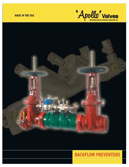
Double Check Valve<strong>Backflow</strong> <strong>Preventers</strong>DC-4A SeriesTOP ENTRY DOUBLE CHECK VALVE ASSEMBLYThe Apollo MODEL DC4A Double Check Valves are designed to prevent contamination of thepotable water supply due to back-siphonage or backpressure from substances that areobjectionable, but non-health hazards. The modular check valves have replaceable seats andreversible silicone seat discs. Apollo ball valves with stainless steel handles and nuts arestandard.Sizes 1/2", 3/4”, 1", 1-1/4", 1-1/2", 2"OPERATIONDuring normal flow conditions, the two check valves are held off their seats, supplying waterdownstream. Each check valve is designed to maintain a minimum of 1 psi across the valveduring normal operation. Should the downstream pressure increase to within 1 psi of supplypressure, both check valves will close to prevent a backflow condition.FEATURESMATERIALSBodyCast Bronze C84400CapsCast Bronze C84400Check Valves Glass-Filled Noryl ®Springs300 Series Stainless SteelSeat DiscsChloramine-resistantSiliconeO-ringsChloramine-resistant EPDM• Low pressure loss• Modular check valves• Compact yet easy to maintain• Apollo ball valves w/ SS handles & nutsstandard• Top access for testing, fast repairand maintenance• Corrosion resistant• No special tools required• Chloramine-resistant elastomers• Patent pending• ASSE 1015 horizontal and vertical flowup• Maximum working pressure 175 psi• Temperature range 33°F - 180°F• Designed, manufactured, assembledand tested in South Carolina, USAFlow Curves : Rated (*) Rated flow flow as as determined by by USC’s ASSE FCCC&HR design andperformance ASSE design standards.performance standards.Dimensions (in)Ordering No. Size A B C D Wt.4A-103-T2 1/2” 10-3/4 7-3/8 3-1/8 2-3/8 4.44A-104-T2 3/4” 12-1/2 8-1/2 3-3/8 3 6.04A-105-T2 1” 15-1/4 9-1/2 3-7/8 3-1/4 104A-106-T2 1-1/4” 18 11-3/4 4-3/8 4-1/4 144A-107-T2 1-1/2” 18-5/8 11-5/8 4-3/8 4-3/4 174A-108-T2 2” 21-1/2 12-3/4 4-7/8 5-3/8 Pend4Customer Service 1-704-841-6000
Double Check Valve<strong>Backflow</strong> <strong>Preventers</strong>DC-40 SeriesTOP ENTRY DOUBLE CHECK VALVE ASSEMBLYThe Apollo DC-40 Series Top Entry Double Check Valve Assembly is designed toprotect against backflow from a cross-connection of non-health hazard pollutant. Within theassembly are two mechanically independent, spring-loaded poppet type check valves set inan integral cast bronze body. Both check valves are designed at an inclined angle upward fromhorizontal centerline of the assembly, and all test cocks are mounted at the top to assure easyaccess during repair and maintenance when unit is installed in a pit or tight places.Sizes 3/4", 1", 1-1/4", 1-1/2", 2"OPERATIONDuring normal flow conditions, the two check valves are held off their seats, supplying waterdownstream. Each check valve is designed to maintain a minimum of 1 psi across the valveduring normal operation. Should the downstream pressure increase to within 1 psi of supplypressure, both check valves will close to prevent a backflow condition.MATERIALSBody and coversSpringsPoppetsSeat discsReplaceable seatsFastenersHandlesBronzeStainless SteelGlass-Filled CelconSilicone RubberGlass-Filled NorylStainless SteelStainless SteelFEATURES• Top access for testing, fast repairand maintenance• Corrosion resistant• Low head loss• Interchangeable poppets and springs• Replaceable seats & Reversible SeatDiscs• Approved for vertical and horizontalinstallations (consult factory for details)• CSA• USC FCCCHR• AWWA C-510• ASSE 1015• Comes standard with Apollo ® full portball valves with stainless steel handles• Maximum working pressure 175 psig• Temperature range 33°F-180°F• Designed, manufactured, assembledand tested in South Carolina, USAORDERING CODE -40 - 1 X X - TXXExample: 40-104-T4LL = 3/4” doublecheck valve assembly with union ballvalves with locking lever handlesY-STRAINER0-Standard1-w/ Y-strainer(shipped loose)SIZE4-3/4"5-1"6-1-1/4"7-1-1/2"8-2"SHUT-OFF VALVES1-less ball valves (UL Classified)2-w/ball valves (Standard)4-w/union ball valvesOPTIONS (CAN BE COMBINED)F-SAE threaded test cocksLL-locking lever handlesFlow Curves : (*) Rated flow as determined by USC’s FCCC&HR andASSE design performance standards.Dimensions (in) – Weights (lbs.)Body Size 3/4" 1" 1-1/4" 1-1/2" 2"A 13 14-3/4 20-3/4 21-3/8 23-1/8B 7-1/4 7-1/4 12-3/8 12-3/8 12-3/8C 4-5/16 4-5/16 6-1/8 6-1/8 6-1/8D 1-5/8 1-7/8 2-3/16 2-5/8 3E 2-7/16 2-7/16 3-13/16 3-13/16 3-13/16F 5-7/16 5-7/16 6-3/8 6-3/8 6-3/8G 13/16 13/16 1-3/8 1-3/8 1-3/8Test Cocks1/8 x 1/4 NPT 1/8 x 1/4 NPT 1/4 x 1/4 NPT 1/4 x 1/4 NPT 1/4 x 1/4 NPTNet Weight 8.8 9.5 23.2 25.7 31.5Shipping Weight 10.1 10.8 25.9 28.8 35.5Customer Service 1-704-841-60005
Double Check Valve<strong>Backflow</strong> <strong>Preventers</strong>DC-4SG SeriesDC-4SG SERIES DOUBLE CHECK VALVE ASSEMBLYThe Apollo ® DC-4SG Series Double Check Valve is designed to prevent contamination of the potablewater supply due to back-siphonage or backpressure from substances that are non-health hazards.The modular check valves have replaceable seats and reversible EPDM seat discs. Grooved connectionson an epoxy-coated ductile iron body allow for easy connection to butterfly valves or gatevalves.Sizes 2-1/2”, 3", 4", 6", 8"MATERIALSBodyEpoxy-coated (FDA)Ductile IronCovers (2-1/2” - 6”) Epoxy-coated (FDA)SteelCovers (8”)Epoxy-coated (FDA)Ductile IronCheck Valves (2-1/2” - 6”) Glass-Filled Noryl ®Check Valves (8”) BronzeSpringsStainless SteelSeat DiscsChloramine-resistantEPDMTest Cock Handles Stainless SteelFEATURES• Lightweight• Short lay length• Low pressure loss• Modular check valves• Individual access to check valves• Reversible/replaceable seat discs• Approved for vertical (up) and horizontalinstallations• Corrosion resistant epoxy-coated ductileiron bodyORDERING CODE -Y-STRAINER0 - None (Standard)1 - With Y-Strainer(Flanged only,shipped loose)SIZE9 - 2-1/2”0 - 3”A - 4”C - 6”E - 8”Example: 4SG-10A-07 = 4” size with OS&Yflanged x grooved shut-off valvesDimensions (in) - Weights (lbs.)Size 2 1/2" 3" 4" 6" 8”A (Butterfly Valves)* 29 29 1/2 29 3/4 32 43A (Gate Valves)* 32 33 34 1/2 39 50B (Grooved End Body) 17 17 16 1/2 18 27C (Butterfly Valves) 8 8 1/2 9 1/4 10 1/4 12C (OS&Y Open) 16 3/8 18 7/8 22 3/4 30 1/8 37 3/4D (Butterfly Valves) 4 1/2 4 1/2 4 1/2 4 1/2 6 1/2D (Gate Valves) 3 1/2 3 1/2 4 1/2 5 1/2 6 3/4E (Butterfly Valves) 9 9 9 1/2 12 15E (Gate Valves) 9 5/8 10 3/8 11 7/8 14 5/8 16 3/4Test Cocks (NPT) 1/2 1/2 1/2 3/4 3/4Net Wt. (Less Valves) 53 53 53 60 375Net Wt. (w/Butterfly Valves) 80 83 97 128 506Net Wt. (w/OS&Y Valves) 149 174 208 309 852*Nominal dimensions are shown. Allowances must be made for manufacturers’ tolerances.• ASSE 1015• CSA• USC FCCCHR• AWWA C-510• UL Classified• FM approved• US Patents #5,711,341 and #6,343,618• MADE IN THE USA4SG - 1 X X - 0 X - USHUT-OFF VALVES (Inlet x Outlet)1 - Less Shut-off Valves (grooved-end body)2 - NRS Flg x NRS Flg3 - OS&Y Flg x OS&Y Flg4 - OS&Y Flg x Monitored Butterfly Valve Grv6 - OS&Y Flg x Flg Post Indicator**7 - OS&Y Flg x OS&Y Grv8 - OS&Y Grv x OS&Y Grv9 - Mon. Butterfly Vlv Grv x Mon. Butterfly Vlv Grv10 - OS&Y Flg x Grv Post Indicator****Post indicator option not available in 2-1/2” sizeFLOW (OPTIONAL)N -N Flow8Customer Service 1-704-841-6000
Sizes 2-1/2”, 3", 4", 6", 8"MATERIALSBody (mainline)Epoxy-coated (FDA)Ductile IronBypass DCBronzeCovers (2-1/2” - 6”) Epoxy-coated (FDA)SteelCovers (8”)Epoxy-coated (FDA)Ductile IronCheck Valves (2-1/2” - 6”) Glass-Filled Noryl ®Check Valves (8”) BronzeSpringsStainless SteelSeat DiscsChloramine-ResistantEPDMTest Cock Handles Stainless SteelDCDA-4SG SeriesDimensions (in) - Weights (lbs.)Size 2 1/2" 3" 4" 6" 8”A (Butterfly Valves)* 29 29 1/2 29 3/4 32 43A (Gate Valves)* 32 33 34 1/2 39 50B (Grooved End Body) 17 17 16 1/2 18 27C (Butterfly Valves) 8 8 1/2 9 1/4 10 1/4 12C (OS&Y Open) 16 3/8 18 7/8 22 3/4 30 1/8 37 3/4D (Butterfly Valves) 4 1/2 4 1/2 4 1/2 4 1/2 6 1/2D (Gate Valves) 3 1/2 3 3/4 4 1/2 5 1/2 6 3/4E 9 9 9 9 10 3/4Test Cocks (NPT) 1/2 1/2 1/2 3/4 3/4Net Wt. (Less Valves) 65 65 65 72 395Net Wt. (w/Butterfly Valves) 92 95 109 140 526Net Wt. (w/OS&Y Valves) 161 186 220 321 872*Nominal dimensions are shown. Allowances must be made for manufacturers’ tolerances.Double Check Detector<strong>Backflow</strong> <strong>Preventers</strong>DCDA-4SG SERIES DOUBLE CHECK DETECTOR ASSEMBLYThe Apollo ® DCDA-4SG Series Double Check Detector Assembly is designed to preventcontamination of the potable water supply due to back-siphonage or backpressure from substancesthat are non-health hazards. The device consists of a mainline double check valve withApollo ® shut-off ball valves as shut-offs. The by-pass serves to measure water use of up to 3 gpm.Grooved connections on an epoxy-coated ductile iron body allow for easy connection to butterflyvalves or gate valves.FEATURES• Lightweight• Short lay length• Low pressure loss• Modular check valves• Individual access to check valves• Reversible/replaceable seat discs• Approved for vertical and horizontalinstallationsORDERING CODE -SIZE9 - 2-1/2”0 - 3”A - 4”C - 6”E - 8”METER OPTIONC - Cubic feet/minE - Gallons/minG - Less meterExample: 4SG-60A-E7 = 4” size with meter ingpm and OS&Y flanged x groovedshut-off valves• Corrosion resistant epoxy-coated ductileiron body• UL Classified• FM approved• USC FCCCHR• ASSE 1048• CSA• US Patents #5,711,341 and #6,343,618• MADE IN THE USA4SG - 6 0 X - X X - USHUT-OFF VALVES (Inlet x Outlet)1 - Less Shut-off Valves (grooved-end body)2 - NRS Flg x NRS Flg3 - OS&Y Flg x OS&Y Flg4 - OS&Y Flg x Monitored Butterfly Valve Grv6 - OS&Y Flg x Flg Post Indicator**7 - OS&Y Flg x OS&Y Grv8 - OS&Y Grv x OS&Y Grv9 - Mon. Butterfly Vlv Grv x Mon. Butterfly Vlv Grv10 - OS&Y Flg x Grv Post Indicator****Post indicator with plate & nut option not available in 2-1/2” sizeFLOW (OPTIONAL)N - N- FlowCustomer Service 1-704-841-60009
Double Check Detector<strong>Backflow</strong> <strong>Preventers</strong>Size 10"DCDA-4S SERIESDOUBLE CHECK DETECTOR ASSEMBLYThe Apollo Model DCDA-4S Double Check Detector Assembly is designed to provide double checkprotection against cross-connection of non-potable (non-hazardous) water into the safe drinkingwater system; and at the same time offers precise monitoring capability to detect leakage or unauthorizeduse of water from fire or automatic sprinkler systems. The unit consists of two independentlyacting, spring loaded check valves with inlet and outlet resilient wedge gate valves and a by-passassembly consisting of a water meter, double check valve assembly with shut-off valves and testcocks.OPERATIONDuring normal conditions, if the downstream pressure of the assembly increases above the supplypressure or there is a reverse direction of flow; the line and by-pass double check valves will closeto prevent backflow. If the second check valve of either the line or by-pass is prevented fromclosing tightly, the first check valves will still provide protection from a backflow condition. The lineand by-pass double check valves will remain closed during the no flow condition. If there is a lowflow demand (up to a minimum of 3 gpm) of water downstream, which may be caused by a systemleak or unauthorized use, the flow is routed through the water meter to monitor such consumption.Higher flow will cause the main line double check valve to open while water continues toflow at the by-pass at a rate below capacity.MATERIALSBody and coversFDA Approved epoxycoated ductile iron(mainline)Bronze (by-pass)By-pass components BronzeSpringsStainless Steel (both)SeatsBronze (both)DiscsEPDM (both)FastenersStainless SteelTest cocksBronze (both)Test cock handles Stainless SteelContact local water authorities forinstallation/service requirements.FEATURES• US Patent #6,343,618• Corrosion Resistant• Reversible/Replaceable Seat Discs• Low <strong>Head</strong> Loss• Economical• Short Lay Length• Designed For Easy Maintenance• Horizontal and vertical installation approvals• Check Valve Assemblies InterchangeableORDERING CODE -SIZEG – 10"Flow Curves : (*) Rated flow as determined by USC’s FCCC&HR and ASSEdesign performance standards.• Maximum Working Pressure 175 PSI• Operating Temperature Range 33˚F-140˚F• UL Classified• FM Approved• USC FCCCHR• ASSE 1048• CSA• Designed, manufactured, assembled andtested in South Carolina, USA4S - 6 0 X - X X XMETERC — With meter in cubic feetE — With meter in gallonsG — Less water meterGATE VALVESFLOW (OPTIONAL)1 — Less gate valvesN – N-Flow3 — With OS&Y gate valves6 — w/OS&Y gate valve on inlet,w/post indicator valve w/plate and nut on outlet7 — W/ Flanged inlet xGrooved outlet (OS&Y)8 — w/Grooved x Grooved OS&Ygate valvesDimensions (in.) – Weights (lbs.)Size 10"A 55-3/4B 29-1/2C (NRS) 26-1/2C (OS&Y OPEN) 46D 8E 10-3/4F 51-3/4G 39-1/2H 11-1/2Test Cocks (Mainline)3/4 NPTTest Cocks (Bypass)1/4 NPTNet. Wt. (Less Gate Valves) 490Net. Wt. (w/OS&Y Valves) 1340Net. Wt. (w/Elbows & OS&Y Valves) 1714Net. Wt. (w/Post Indicator) 1277Shpg. Wt. (Less Gate Valves) 585Shpg. Wt. (w/OS&Y Valves) 1440Shpg. Wt. (w/Elbows & OS&Y Valves) 1814Shpg. Wt. (w/Post Indicator) 1377*Nominal dimensions are shown. Allowances must be made formanufacturers’ tolerances.10Customer Service 1-704-841-6000
Sizes 1/4", 3/8", 1/2", 3/4", 1",1-1/4", 1-1/2", 2"MATERIALSBody and coversSpringsPoppetsSeat DiscsDiaphragmR.V. StemFastenersReplaceable SeatsTest Cock HandlesContact local water authorities forinstallation/service requirements.BronzeStainless SteelGlass-Filled CelconSilicone RubberNitrile and NylonNorylStainless SteelGlass-Filled NorylStainless SteelFlow Curves : (*) Rated flow as determined by USC’s FCCC&HR andASSE design performance standards.RP-40 SeriesReduced Pressure<strong>Backflow</strong> <strong>Preventers</strong>REDUCED PRESSURE PRINCIPLEThe Apollo Series RP-40 Reduced Pressure Principle <strong>Backflow</strong> Preventer is designed to give maximumprotection against backflow caused by either back-pressure or back-siphonage. Thedurable, but economical, device is easily maintained in the line without any special tools. It consistsof two independently acting spring-loaded check valves with an automatic differential reliefvalve located between the check valves. The diaphragm and the sensing passage are built intothe all bronze body to eliminate possible damage. Three of the testcocks are mounted at the topto assure easy access during repair and maintenance when unit is installed in tight places.FEATURES• Maximum protection against back-pressure/back-siphonage• Reversible/Removable silicone seat discs• Internal sensing passage• Designed for easy maintenance• Low head loss• Economical• Corrosion resistant• Replaceable seat rings• Comes standard with Apollo ® full portball valves with stainless steel handlesORDERING CODE -Y-STRAINER0-Standard1-w/ Y-strainer (shipped loose)• Maximum working pressure 175 psig• Operating temperature range 33°F-180°F• Replaceable seats• UL Classified (less shut-offs)• USC FCCCHR• AWWA 511• ASSE 1013• Designed, manufactured, assembled andtested in South Carolina, USA40 - 2 X X - T X XSIZE1-1/4"2-3/8"3-1/2"4-3/4"5-1"6-1-1/4"7-1-1/2"8-2"SHUT-OFF VALVES1-less ball valves (UL Classified)2-w/ball valves (Standard)4-w/union ball valvesOPTIONS (CAN BE COMBINED)F-SAE threaded test cocksLL-locking lever handlesExample: 40-215-T4LL = 1” Reduced Pressure <strong>Backflow</strong>Preventer with strainer, union ball valves andlocking lever handlesSee page 37 for air gap drain information.Dimensions (in.) – Weights (lbs.)Body Size 1/4" 3/8" 1/2" 3/4" 1" 1-1/4" 1-1/2" 2"A 10-3/16 10-1/4 10-3/4 13-3/4 15-3/8 17-1/2 19-1/2 21-1/2B (w/o Ball Valves) 5-3/4 5-3/4 5-3/4 8 8 11 11 11C 6-7/8 6-7/8 6-7/8 9-3/4 9-3/4 12-5/8 12-5/8 12-5/8D 2-5/8 2-5/8 2-5/8 4-1/16 4-1/16 5-3/8 5-3/8 5-3/8E 3-1/8 3-1/8 3-1/8 4-1/2 4-1/2 5-11/16 5-11/16 5-11/16F 3-3/4 3-3/4 3-3/4 5-1/8 5-1/8 7-1/8 7-1/8 7-1/8Test Cocks 1/8x1/4NPT 1/8x1/4NPT 1/8x1/4NPT 1/8x1/4NPT 1/8x1/4NPT 1/4x1/4NPT 1/4x1/4NPT 1/4x1/4NPTNet Wt. (w/o Ball Valves) 5.7 5.7 5.1 11-1/2 11 30-1/2 27-1/2 27Net Wt. (w/ Ball Valves) 7 7 7.4 14 14-1/2 35-1/2 37 39-1/2Shpg. Wt. (w/o Ball Valves) 6.6 6.6 6 12-1/2 12 32-1/2 29 29Shpg. Wt. (w/ Ball Valves) 7.9 7.9 8.3 15 15-1/2 38 39 41Customer Service 1-704-841-600011
Reduced Pressure<strong>Backflow</strong> <strong>Preventers</strong>RP-40 SeriesN AND Z FLOW REDUCED PRESSURE PRINCIPLEThe Apollo Series RP-40 Reduced Pressure Principle <strong>Backflow</strong> Preventer is designed to givemaximum protection against backflow caused by either back-pressure or back-siphonage. Thedurable, but economical, device is easily maintained in the line without any special tools. It consistsof two independently acting spring-loaded check valves with an automatic differential reliefvalve located between the check valves. The diaphragm and the sensing passage are built intothe all bronze body to eliminate possible damage. The assembly offers installation flexibility byproviding inlet and outlet bronze elbows to meet space requirements, adaptability and lowerinstallation cost. The No. 3 and No. 4 test cocks are mounted at the top to assure easy accessduring repair and maintenance when unit is installed in tight places.Shown withoption (F) -SAE threadedtest cocksZ-FlowOPERATIONDuring normal flow conditions, the two check valves are held off their seats, supplying water downstream.The relief valve is held shut by supply pressure acting through the internal sensing passage,on the relief valve diaphragm. In the area between the check valves, called the zone, the pressure ismaintained at approximately 7 psi lower than supply pressure. Should a back-pressure or backsiphonagecondition occur, the second check valve will seal, prohibiting the backflow of water. Shouldthe second check valve become fouled, the pressure in the zone will increase causing the differentialrelief valve to open to atmosphere. This will maintain the pressure in the zone at least 2 psi lowerthan supply pressure.N-FlowSizes 3/4", 1", 1-1/4", 1-1/2", 2"MATERIALSBody, covers& elbowsSpringsPoppetsSeat DiscsDiaphragmR.V. StemFastenersReplaceable SeatsTest Cock HandlesBronzeContact local water authorities forinstallation/service requirements.Stainless SteelGlass-Filled CelconSilicone RubberNitrile and NylonNorylStainless SteelGlass-Filled NorylStainless SteelFEATURES• Maximum protection against back-pressure/back-siphonage• Flexibility in installation• Low installation cost• Compact• Internal sensing passage• Low head loss• Reversible/Removable seat discs• Replaceable seat ringsORDERING CODE -SIZES4-3/4"5-1"6-1-1/4"7-1-1/2"8-2"• Comes standard with Apollo ® full portball valves with stainless steel handles• Maximum working pressure 175 psig• Temperature range 33°F-180°F• UL Classified (less shut-offs)• USC FCCCHR• AWWA 511• ASSE 1013• CSA• Designed, manufactured, assembled andtested in South Carolina, USA40 - 2 0 X - T X X XSHUT-OFF VALVES1-less ball valves (UL Classified)2-w/ball valves (Standard)4-w/union ball valvesFLOWN - N-FlowZ - Z-FlowExample: 40-204-T4ULL = 3/4” Reduced Pressure <strong>Backflow</strong>Preventer with union ball valves, with U-flow, and lockinglever handlesOPTIONS (CAN BE COMBINED)F-SAE threaded test cocksLL-locking lever handlesFlow Curves : (*) Rated flow as determined by USC’s FCCC&HR and ASSE design performance standards.See page 37 for air gap drain information.Dimensions (in.) – Weights (lbs.)Body Size 3/4" 1" 1-1/4" 1-1/2" 2"A 10-1/2 10-11/16 14-3/16 15-1/8 15-3/4B 8 8 11 11 11C 4-1/8 5-3/16 6 6-5/8 7-5/8D 4-7/16 4-9/16 5-3/4 5-7/8 6-1/4E 13-7/8 15-1/8 19 20-3/4 22-1/8F 4-7/16 4-7/16 5-11/16 5-11/16 5-11/16G 5-1/8 5-1/8 7-1/8 7-1/8 7-1/8Test Cocks1/8 x 1/4NPT 1/8 x 1/4NPT 1/4 x 1/4NPT 1/4 x 1/4NPT 1/4 x 1/4NPTNet Wt. (with Ball Valves) 14.7 15.6 37.5 39.37 43.75Shpg. Wt. (with Ball Valves) 15.7 16.6 40 41.37 45.2512Customer Service 1-704-841-6000
RP-40 SeriesReduced Pressure<strong>Backflow</strong> <strong>Preventers</strong>REDUCED PRESSURE PRINCIPLEThe Apollo Series 40-RP Reduced Pressure <strong>Backflow</strong> Preventer consists of twoindependently acting, spring-loaded check valves with a differential pressure relief valvelocated between the check valves. The all bronze relief valve module is easily removed fromthe ductile iron check valve body. Pressure sensing passages are built into the bronze reliefvalve module to prevent possible damage from mishandling or vandalism. The unit isavailable with inlet and outlet shutoff valves. Four test cocks, three on the backflow preventervalve body and one on the inlet shutoff valve, complete the assembly.Sizes 2-1/2", 3", 4"OPERATIONDuring normal flow conditions, the two check valves are held off their seats, supplyingwater downstream. The relief valve is held shut by supply pressure acting through theinternal sensing passage, on the relief valve diaphragm. In the area between the checkvalves, called the zone, the pressure is maintained at approximately 7 psi lower thansupply pressure. Should a back-pressure or back-siphonage condition occur, the secondcheck valve will seal, prohibiting the backflow of water. Should the second check valvebecome fouled, the pressure in the zone will increase causing the differential relief valve toopen to atmosphere. This will maintain the pressure in the zone at least 2 psi lower thansupply pressure.MATERIALSBody and coverSpringsSeatsC.V. DiscsR.V. DiscR.V. DiaphragmR.V. BodyFastenersTest Cock HandlesContact local water authorities forinstallation/service requirements.Epoxy Coated(FDA Approved)Ductile IronStainless SteelBronzeEPDMSiliconeNitrile and NylonBronzeStainless SteelStainless SteelFEATURES• Maximum protection against backpressure/back-siphonage• Reversible/Removable seat discs• Replaceable bronze seats• Internal sensing passage• Designed for easy maintenance• Low head loss• Economical• Corrosion resistant• Maximum working pressure 175 psigORDERING CODE -• Operating temperature range 33°F -140°F• UL Classified• FM approved• USC FCCCHR• ASSE 1013• CSA• AWWA 511• Designed, manufactured, assembledand tested in South Carolina, USA40 - 2 X X - 0 XFlow Curves : (*) Rated flow as determined by USC’s FCCC&HR and ASSE designperformance standards.Y-STRAINER0-Standard1-w/ epoxy Y-strainer(shipped loose)SIZE9-2-1/2"0-3"A-4"VALVES1-less gate valves2-w/ NRS gate valves3-w/OS&Y gate valves5-w/Epoxy coated ball valvesDimensions (in.) – Weights (lbs.)Body Size 2-1/2" 3" 4"A 37-1/16 38-1/16 46-3/4B 22-1/16 22-1/16 28-1/2C NRS 20-7/8 21-7/8 25-3/16C OS&Y (OPEN) 25-7/8 28-3/8 33-3/16D NRS 11-3/8 12-3/8 14-3/4D OS&Y (OPEN) 16-3/8 18-7/8 22-3/4E 9-1/2 9-1/2 10-7/16F 9-5/8 10-3/8 11-7/8G 7 7-1/2 9Test Cocks1/2 x 1/2 NPT 1/2 x 1/2 NPT 1/2 x 1/2 NPTNet Wt. (Less Gate Valves) 120 122 196Net Wt. (With NRS Valves) 219 252 388Net Wt. (With OS&Y Valves) 229 259 402Net Wt. (With Ball Valves) 188 198 312Shpg. Wt. (Less gate Valves) 184 186 260Shpg. Wt. (With NRS Valves) 283 316 452Shpg. Wt. (With OS&Y Valves) 293 323 466Shpg. Wt. (With Ball Valves) 252 262 376Customer Service 1-704-841-600013
Reduced Pressure<strong>Backflow</strong> <strong>Preventers</strong>MATERIALSBody and coversSpringsSeatsC.V. DiscsR.V. DiscR.V. DiaphragmR.V. BodyR.V. BodyFastenersTest Cock HandlesSizes 6", 8", 10"Contact local water authorities forinstallation/service requirements.Epoxy Coated(FDA Approved)Ductile IronStainless SteelBronzeEPDMSiliconeNitrile and NylonBronze – For 6" onlyEpoxy Coated(FDA Approved)Ductile Iron –For 8" and 10" onlyStainless SteelStainless SteelRP-40 SeriesREDUCED PRESSURE PRINCIPLEThe Apollo Series RP-40 Reduced Pressure <strong>Backflow</strong> Preventer consists of two independentlyacting, spring-loaded check valves with a differential pressure relief valve located between thecheck valves. The relief valve module is easily removed from the ductile iron check valve body.Pressure sensing passages are built into the relief valve module to prevent possible damagefrom mishandling or vandalism. The unit is available with inlet and outlet shutoff valves. Fourtest cocks, three on the backflow preventer valve body and one on the inlet shutoff valve, completethe assembly.OPERATIONDuring normal flow conditions, the two check valves are held off their seats, supplying waterdownstream. The relief valve is held shut by supply pressure acting through the internal sensingpassage, on the relief valve diaphragm. In the area between the check valves, called thezone, the pressure is maintained at approximately 7 psi lower than supply pressure. Should aback-pressure or back-siphonage condition occur, the second check valve will seal, prohibitingthe backflow of water. Should the second check valve become fouled, the pressure in the zonewill increase causing the differential relief valve to open to atmosphere. This will maintain thepressure in the zone at least 2 psi lower than supply pressure.FEATURES• Maximum protection against backpressure/back-siphonage• Removable bronze seats• Reversible/Replaceable seat discs• Internal sensing passage• Designed for easy maintenance• Low head loss• Economical• Corrosion resistantORDERING CODE -• Maximum working pressure 175 psig• Operating temperature range 33°F-140°F• UL Classified• FM approved• USC FCCCHR• ASSE 1013• CSA• AWWA 511• Designed, manufactured, assembledand tested in South Carolina, USA40 - 2 X X - 0 XFlow Curves : (*) Rated flow as determined by USC’s FCCC&HR and ASSE designperformance standards.Y-STRAINER0-Standard1-w/ epoxy Y-strainer (shipped loose)SIZEC-6"E-8"G-10"VALVES1-less gate valves2-w/ NRS gate valves3-w/OS&Y gate valves5-w/Epoxy coated ball valvesDimensions (in.) – Weights (lbs.)Body Size 6" 8" 10"A 63 75 88-1/4B 42 52 62-1/16C NRS 30-1/2 38-1/2 44C OS&Y (OPEN) 41-5/8 53-3/4 63-1/4D NRS 19 22-1/2 26-1/2D OS&Y (OPEN) 30-1/8 37-3/4 45-34E 11-1/2 16 17-1/2F 14-5/8 16-3/4 19-1/4G 11 13-1/2 16Test Cocks3/4 x 3/4 NPT 3/4 x 3/4 NPT 3/4 x 3/4 NPTNet Wt. (Less Gate Valves) 430 715 1443Net Wt. (With NRS Valves) 736 1155 2148Net Wt. (With OS&Y Valves) 754 1210 2286Net Wt. (With Ball Valves) 666 N/A N/AShpg. Wt. (Less gate Valves) 528 885 1613Shpg. Wt. (With NRS Valves) 872 1335 2364Shpg. Wt. (With OS&Y Valves) 890 1390 2502Shpg. Wt. (With Ball Valves) 836 N/A N/ASee page 37 for air gap drain information.14Customer Service 1-704-841-6000
Reduced Pressure<strong>Backflow</strong> <strong>Preventers</strong>RP-40 SeriesFIRE HYDRANT BACKFLOW METERThe Apollo Series RP-40 Fire Hydrant <strong>Backflow</strong> Meter shall measure potable water flow froma fire hydrant or other non-permanent installation. At the same time it shall protect against backflowby either back-pressure or back-siphonage from a cross-connection between potable water systemand substances that are non-health and health hazards. The unit shall consist of a 3/4" Short WaterMeter, 1" 40-205 RP device, 1" resilient-seated full port ball valve with locking device, 2 1/2"-7 1/2"NST threaded hose couplings, strainer on inlet of meter and adjustable support rod assembly.Size 1"OPERATIONThe Fire Hydrant <strong>Backflow</strong> Meter is connected directly to a fire hydrant with a 2 1/2"-7 1/2" NST firehose female swivel coupling. The device operates like a standard Reduced Pressure device exceptthe flow through the device is measured by a Water Meter connected to the inlet of the backflowpreventer. Support rod assembly is adjustable to accommodate fire hydrants at different heightsfrom the ground.Contact local water authorities forinstallation/service requirements.FEATURES• Normal operating flow range 2-30 gpm• Accuracy 100% ± 1.5% of actual thruput• Low flow registration 95% at 1/2 gpm• Maximum pressure loss 11.0 psi at 30 gpm• Maximum operating pressure 150 psi• Measuring element oscillating piston• Register is straight reading, hermeticallysealed magnetic drive• Meter maincase is bronze, measuringchamber is Rocksyn, a corrosion resistantthermoplastic material, maincase bottomplate is bronze, gears are self-lubricating,molded plastic for long life and minimumfriction, magnets are Alnico, trim andcasing bolts are stainless steel and straineris thermoplastic.DIMENSIONS (in.)—WEIGHTS (lbs.)NET WEIGHT 24.1SHIPPING WEIGHT 27.6• Tamperproof locking system insidethe meter• 2 1/2"-7 1/2" NST fire hose swivelcouplings, female inlet, male outlet• Maximum rate listed is for intermittentflow only. Maximum continuous flow rateas specified by AWWA is 15 gpm.• Designed, manufactured, assembled andtested in South Carolina, USAModel Number40-205-FHB (meter in cu. ft.)40-205-FHBG (meter in gallons)See page 37 for air gap drain information.Customer Service 1-704-841-600015
Reduced Pressure<strong>Backflow</strong> <strong>Preventers</strong>Sizes 1/4", 3/8", 1/2", 3/4", 1"MATERIALSBody and CoverSpringsFastenersPoppetsSeat DiscsDiaphragmand O-RingsReplaceable SeatsTest Cocks & HandlesContact local water authorities forinstallation/service requirements.Stainless SteelStainless SteelStainless SteelGlass-Filled CelconSilicone RubberFDA FluorocarbonGlass-Filled NorylStainless SteelRP-40S SeriesSTAINLESS STEEL REDUCED PRESSURE PRINCIPLEBACKFLOW PREVENTERThe Apollo Series RP-40S Stainless Steel Reduced Pressure Principle <strong>Backflow</strong> Preventer isdesigned to give maximum protection against backflow caused by either backpressure or backsiphonagefrom a cross-connection wherein a contaminant hazard exists (i.e. a health hazard),or a pollutant hazard exists (i.e. a non-hazard). The assembly is composed of two spring-loadedpoppet type check valves and a mechanically independent, hydraulically dependent pressuredifferential relief valve set in an integral stainless steel body. Three of the testcocks are mountedat the top to assure easy access during repair and maintenance when unit is installed intight places.OPERATIONDuring normal flow conditions, the two check valves are held off their seats, supplying waterdownstream. The relief valve is held shut by supply pressure acting through the internal sensingpassage, on the relief valve diaphragm. In the area between the check valves, called thezone, the pressure is maintained at approximately 7 psi lower than supply pressure. Should aback-pressure or back-siphonage condition occur, the second check valve will seal, prohibitingthe backflow of water. Should the second check valve become fouled, the pressure in the zonewill increase causing the differential relief valve to open to atmosphere. This will maintain thepressure in the zone at least 2 psi lower than supply pressure.FEATURES• Stainless steel body and covers• Easy to install and repair• Internal sensing passage• Low head loss• Reversible/Removable seat discs• Replaceable seats• Comes standard with Apollo ® stainless steelfull port ball valves with stainless steel handles• Maximum working pressure 175 psig• Temperature range 33°F-180°F• USC FCCCHR• ASSE 1013• CSA• Designed, manufactured, assembled andtested in South Carolina, USAORDERING CODE -40 - 2 X X - T X SOPTIONS (CAN BE COMBINED)F-SAE threaded test cocksLL-locking lever handlesFlow Curves : (*) Rated flow as determinedby USC’s FCCC&HR and ASSEdesign performance standards.Y-STRAINER0-Standard1-w/ SS Y-strainer(shipped loose)SIZE1-1/4"2-3/8"3-1/2"4-3/4"5-1"SHUT-OFF VALVES1-less ball valves (UL classified-3/4”,1”)2-w/SS ball valves (Standard)See page 37 for air gap drain information.Dimensions (in.) – Weights (lbs.)Body Size 1/4" 3/8" 1/2" 3/4" 1"A 10-1/2 10-1/2 10-1/2 13-1/2 15-1/4B 5-3/4 5-3/4 5-3/4 7-15/16 7-15/16C 6-7/8 6-7/8 6-7/8 9 9D 2-5/8 2-5/8 2-5/8 4-1/16 4-1/16E 3-3/16 3-3/16 3-3/16 4-3/8 4-3/8F 3-3/4 3-3/4 3-3/4 5-1/8 5-1/8Test Cocks1/8 x 1/4NPT 1/8 x 1/4NPT 1/8 x 1/4NPT 1/8 x 1/4NPT 1/8 x 1/4NPTNet Wt. (w/o Ball Valves) 4-1/4 4-1/4 4-1/8 8-1/4 8-1/8Net Wt. (with Ball Valves) 5-1/2 5-1/2 5-3/8 10-3/4 11Shpg. Wt. (w/o Ball Valves) 5-1/8 5-1/8 5 9-3/4 9-5/8Shpg. Wt. (with Ball Valves)6-3/8 6-3/8 6-1/4 12-1/4 12-3/416Customer Service 1-704-841-6000
RP-4D Series DEFENDER ®Reduced Pressure<strong>Backflow</strong> <strong>Preventers</strong>RP-4D SERIES REDUCED PRESSURE PRINCIPLE ASSEMBLYThe Apollo Valves RP-4D Reduced Pressure <strong>Backflow</strong> Preventer Defender provides maximumbackflow protection in a lead free, short lay length, compact package. The assembly consists oftow independently acting, spring loaded, poppet type check valves with a differential pressure reliefvalve located in the zone between the checks. The all stainless steel check valve modules areeasily removed from the ductile iron body via a large access cover. The stainless steel relief valvemodule is also accessible and removable. The Defender is available with monitored butterflyvalves. Ninety-degree elbows are also available within the shut-off valve envelope for compactinstallations.2-1/2” - 10”Shown w/ Optional Butterfly ShutoffsMATERIALSBody and coverFusion Bonded EpoxyCoated Ductile IronTest Cocks & Handles Stainless SteelCheck Components Stainless SteelRelief ValveStainless Steel(Noryl Seat on 2.5”-6”SpringsStainless SteelSeat DiscsSilicone RubberFastenersStainless SteelElbowsFusion Bonded EpoxyCoated Ductile IronContact local water authorities forinstallation/service requirements.OPERATIONDuring normal flow conditions, the two poppet style check valves are held off their seats, supplyingwater downstream. The relief valve is held shut by supply pressure acting through the sensingtube. Should a back-pressure or back-siphonage condition occur, the second check will seal,prohibiting the backflow of water. Should the second check become fouled, the pressure in thezone will increase causing the differential relief valve to open to atmosphere, discharging the contentsof the zone.FEATURES• Low Pressure Loss Characteristics(without high curve spikes)• 316 Stainless Steel Checks Provide SuperiorDurability• Reversible/Replaceable Silicone RubberSeat Discs• Available with Monitored ButterflyValves• Short Lay Length• Maximum working pressure 175 PSI• Operating temperature range 33°F-140°F• UL Classified• FM approved• ASSE 1013• AWWA 511• CSA• US Patent #6,443,184 B1(other patents pending)• Designed, manufactured, assembled andtested in South Carolina, USAORDERING CODE -4D - 2 0 X - 0 X XPRESSURE LOSS (PSI)SIZE9 -2-1/2”0 - 3”A - 4”C - 6”E - 8”G -10”GATE VALVES1* - Less Shut-off Valves9 - With Grooved x Grooved Butterflyvalves (Supervisory switch)FLOW (OPTIONAL)U - with twoelbows (canbe field adjustedup or down)*4D Defender valve body has grooved x grooved connectionsFLOW RATE (GPM)See page 37 for air gap drain information.Dimensions (in) - Weights (lbs.)Size 2 1/2" 3" 4" 6" 8” 10”A (Butterfly Valves) 33 3/8 33 7/8 35 38 1/2 48 52 1/2B 21 3/8 21 3/8 21 3/8 24 1/2 32 32C (With Butterfly Valves) 10 5/8 10 5/8 10 5/8 13 15 15D 10 3/4 10 3/4 10 3/4 11 3/4 15 1/4 15 1/4E1 (center to coupling edge) 6 1/2 6 1/2 6 1/2 7 3/4 10 10F (w/Elbows & Butterfly Valves) 8 8 1/2 9 1/4 10 1/4 12 3/4 14 1/2G 22 23 25 29 46 50 1/4H “U” Flow (with Butterfly Valves) 20 3/8 21 1/8 22 3/8 26 1/2 29 3/4 34I “Z” Flow (with Butterfly Valves) 19 1/2 21 23 1/4 27 30 38Test Cocks 1/2 NPT 1/2 NPT 1/2 NPT 3/4 NPT 3/4 NPT 3/4 NPTNet Wt. (Less Gate Valves) 109 110 115 198 417 422Net Wt. (w/Butterfly Valves) 132 134 154 261 539 604Net Wt. (w/Elbows & Butterfly Vlvs) 141 146 174 298 581 712Shpg. Wt. (Less Gate Valves) 173 174 179 296 493 498Shpg. Wt. (w/Butterfly Valves) 199 201 221 369 615 680Shpg. Wt. (w/Elbows & Butter Vlvs) 208 213 241 406 681 812Customer Service 1-704-841-600017
Reduced Pressure<strong>Backflow</strong> <strong>Preventers</strong>RPDA-40 SeriesMATERIALSBody and coversSizes 3", 4"FDA Approved epoxycoatedductile iron(mainline),By-pass (bronze)By-pass components BronzeSpringsStainless Steel (both)SeatsBronze (both)C.V. discs EPDM (mainline)Silicone rubber (by-pass)R.V. discs Silicone rubber(mainline)EPDM (by-pass)Diaphragm Nitrile and nylon (both)R.V. body Bronze (mainline)Fasteners Stainless Steel (both)Test cock handles Stainless SteelContact local water authorities forinstallation/service requirements.REDUCED PRESSURE DETECTOR ASSEMBLYThe Apollo Series RPDA-40 Reduced Pressure Detector Assembly is designed to providereduced pressure principle protection against cross-connections that present a health hazard,and at the same time detect leakage or unauthorized use of water from fire or automatic sprinklersystems. The mainline unit consists of two independent spring-loaded, poppet type check valveassemblies with a diaphragm actuated and spring-loaded, relief valve assembly located betweencheck valves. Two resilient wedge gate valves and four test cocks complete the mainline unit. Theby-pass consists of an approved reduced pressure assembly, four test cocks, two shut-off valvesand a water meter.OPERATIONDuring no flow conditions, the mainline and by-pass check valves will remain closed. Also, bothmainline and by-pass relief valves stay closed due to the pressure differential between supply andzone pressure. If there is a low flow demand (up to a minimum of 3 gpm) of water downstream,which may be caused by a system leak or unauthorized use, the flow is routed through the watermeter to monitor such consumption. Higher flow will tend to open the mainline check valves atwhich water continues to flow at the by-pass at a rate below capacity. In the event pressureincreases downstream, tending to reverse direction of flow, both check valves in the mainline andby-pass are closed to prevent backflow. If the second check valve in either the mainline or by-passis prevented from closing tightly, leakage into the reduced pressure zone increases pressure andwill cause the relief valves to open. If the supply pressure drops to atmosphere or lower than thereduced pressure zone, the relief valves will open creating an internal air gap in both assemblies.Contact local water authorities for installation/service requirements.FEATURES• Maximum protection againstback-pressure/back-siphonage• Removable bronze seats• Reversible/replaceable seat discs• Internal sensing passage• Corrosion resistant• Easy in-line maintenance and testing• Maximum working pressure 175 psigORDERING CODE -40 - 7 0 X - X X• Operating temperature range 33°F-140°F• UL Classified• FM approved• USC FCCCHR• ASSE1047• CSA• Designed, manufactured, assembled andtested in South Carolina, USASIZE0 — 3"A — 4"Flow Curves : (*) Rated flow as determined by USC’s FCCC&HR and ASSEdesign performance standards.METERC — With meter in cubic feetE — With meter in gallonsG — Less water meterGATE VALVES1 — Less gate valves3 — With OS&Y gate valves6 — w/OS&Y gate valve on inlet,NRS gate valve w/ postplate and nut on outlet7 - With Flanged Inlet x GroovedOutlet (both OS&Y)8 - With Grooved x GroovedOS&Y gate valvesSee page 37 for air gap drain information.Dimensions (in.) – Weights (lbs.)Size 3" 4"A 38-1/16 46-3/4B 22-1/16 28-1/2C (OS&Y) OPEN 18-7/8 22-3/4D 3-3/4 4-1/2E (OS&Y) OPEN 28-3/8 33-3/16F 9-1/4 10-1/2G 3-3/4 4-1/2Test cocks (line) 1/2" NPT 1/2" NPTTest cocks (by-pass) 1/4" NPT 1/4" NPTNet Wt. (less gate valves) 145 217Net Wt. (with 0S&Y valves) 282 423Shipping Wt. (less gate valves)209 281Shipping Wt. (with OS&Y valves) 346 48718Customer Service 1-704-841-6000
MATERIALSBody and coversSizes 6",8”, 10"FDA Approved epoxycoatedductile iron (mainline),By-pass (bronze)By-pass components BronzeSpringsStainless Steel (both)SeatsBronze (both)C.V. discsEPDM (mainline)Silicone rubber (by-pass)R.V. discsSilicone rubber(mainline)EPDM (by-pass)Diaphragm Nitrile and nylon (both)Mainline R.V. body Bronze (6" only)FDA Approved epoxycoatedductileiron (8" & 10")Fasteners Stainless Steel (both)Test cock handles Stainless SteelContact local water authorities forinstallation/service requirements.RPDA-40 SeriesSIZEC — 6"E — 8"G — 10"Reduced Pressure<strong>Backflow</strong> <strong>Preventers</strong>REDUCED PRESSURE DETECTOR ASSEMBLYThe Apollo Series RPDA-40 Reduced Pressure Detector Assembly is designed to provide reducedpressure principle protection against cross-connections that present a health hazard, and at thesame time detect leakage or unauthorized use of water from fire or automatic sprinkler systems.The mainline unit consists of two independent spring-loaded, poppet type check valve assemblieswith a diaphragm actuated and spring-loaded assembly located between check valves. Tworesilient wedge gate valves and four test cocks complete the mainline unit. The by-pass consistsof an approved reduced pressure assembly, four test cocks, two shut-off valves and a water meter.OPERATIONDuring no flow conditions, the mainline and by-pass check valves will remain closed. Also, bothmainline and by-pass relief valves stay closed due to the pressure differential between supply andzone pressure. If there is a low flow demand (up to a minimum of 3 gpm) of water downstream,which may be caused by a system leak or unauthorized use, the flow is routed through the watermeter to monitor such consumption. Higher flow will cause the mainline check valves to openwhile water continues to flow at the by-pass at a rate below capacity. In the event pressureincreases downstream, tending to reverse direction of flow, both check valves in the mainline andby-pass are closed to prevent backflow. If the second check valve in either the mainline or by-passis prevented from closing tightly, leakage into the reduced pressure zone increases pressure andwill cause the relief valves to open. If the supply pressure drops to atmosphere or lower than thereduced pressure zone, the relief valves will open creating an internal air gap in both assemblies.FEATURES• Maximum protection against backpressure/backsiphonage• Removable bronze seats• Reversible/replaceable seat discs• Internal sensing passage• Corrosion resistant• Easy in-line maintenance and testing• Maximum working pressure 175 psigORDERING CODE -Flow Curves : (*) Rated flow as determined by USC’s FCCC&HR and ASSEdesign performance standards.• Operating temperature range 33°F-140°F• UL Classified• FM approved• USC FCCCHR• ASSE 1040• CSA• Designed, manufactured, assembled andtested in South Carolina, USA40 - 7 0 X - X XMETERC — With meter in cubic feetE — With meter in gallonsG — Less water meterGATE VALVES1 — Less gate valves3 — With OS&Y gate valves6 — w/OS&Y gate valve on inlet,NRS gate valve w/ postplate and nut on outlet7 - With Flanged Inlet x GroovedOutlet (both OS&Y)8 - With Grooved x GroovedOS&Y gate valvesSee page 37 for air gap drain information.Dimensions (in.) – Weights (lbs.)Size 6" 8" 10"A 63 75 88-1/4B 42 52 62-1/16C (OS&Y) OPEN 30-1/8 37-3/4 45-3/4D 5-1/2 6-3/4 8E (OS&Y) OPEN 41-5/8 53-3/4 63-1/4F 13-1/4 14-3/4 17-1/2G 5-1/2 6-3/4 8Test cocks (line) 3/4" NPT 3/4" NPT 3/4" NPTTest cocks (by-pass) 1/2" NPT 1/4" NPT 1/4" NPTNet Wt. (less gate valves) 452 738 1471Net Wt. (with 0S&Y valves) 776 1233 2314Shipping Wt. (less gate valves)550 908 1641Shipping Wt. (with OS&Y valves) 912 1413 2530Customer Service 1-704-841-600019
Reduced Pressure<strong>Backflow</strong> <strong>Preventers</strong>MATERIALSBody and coverCoatedTest CocksCheck ComponentsRelief ValveSpringsSeat DiscsFastenersElbows2-1/2” - 10”Shown w/ Optional Butterfly ShutoffsContact local water authorities forinstallation/service requirements.Fusion Bonded EpoxyDuctile Iron (mainline)Bronze (by-pass)Stainless Steel (mainline)Bronze (by-pass)Stainless Steel (mainline)Acetal (by-pass)Stainless Steel(Noryl Seat on 2.5”-6”)Stainless SteelSilicone RubberStainless SteelFusion Bonded EpoxyCoated Ductile IronRPDA-4D Series DEFENDER ®4D SERIES REDUCED PRESSURE DETECTOR ASSEMBLYThe Apollo model RPDA-4D Series is designed to provide reduced pressure principle protectionagainst cross-connections that present a health hazard; and at the same time offers precisemonitoring capability to detect leakage or unauthorized use of water from the fire or automaticsprinkler system. The RPDA-4D Series is available in sizes 2-1/2” - 10”. The unit consists of amainline 4D Series Reduced Pressure Principle assembly with two independently acting poppettype check valves with a diaphragm actuated and spring loaded relief valve assembly locatedbetween the checks. A bronze by-pass line by-passes the 2nd check. The by-pass line consists ofa meter, a single check, shut-off isolation valves, and test cocks. The relief valve on the mainlinedevice maintains high hazard protection, as the by-pass is downstream of the reduced pressurezone.OPERATIONDuring normal conditions, the mainline device provides normal reduced pressure backflowprotection against back-siphonage or backpressure. If a backflow condition should occur the twomainline poppet style checks along with the by-pass single check will close tight. If there is a lowflow demand (up to a minimum of 2 gpm) of water downstream, which may be caused by a systemleak or unauthorized use, the flow is routed through the water meter to monitor such consumption.Higher flows will open the mainline checks as required.FEATURES• Low pressure loss characteristics(without high curve spikes)• 4D Series Mainline Valve ProvidesSuperior Durability• Low Maintenance By-Pass Line(no relief valve to maintain)• Reversible/Replaceable Silicone RubberSeat Discs• Dependable Neoperl Check ModuleUtilized in Single Check• Available with Monitored Butterfly Valves• Short Lay Length• Maximum working pressure 175 PSI• Operating temperature range 33°F-140°F• UL Classified• FM approved• ASSE1047• CSA• US Patent #6,443,184 B1(other patents pending)• Easy Access for Maintenance• Designed, manufactured, assembled andtested in South Carolina, USAORDERING CODE -4D - 7 0 X - X X XSIZE9 -2-1/2”0 -3”A -4”C -6”E -8”G-10”METERC - With Meter in CubicFeetE - With Meter in GallonsG - Less MeterGATE VALVES1* - Less Shut-off Valves9 - With Grooved x Grooved Butterflyvalves (Supervisory switch)*4D Defender valve body hasgrooved x grooved connectionsFLOW (OPTIONAL)U - with twoelbows (canbe field adjustedup or down)See page 37 forair gap drain information.20Dimensions (in) - Weights (lbs.)Size 2 1/2" 3" 4" 6" 8” 10”A (Butterfly Valves) 33 3/8 33 7/8 35 38 1/2 48 52 1/2B 21 3/8 21 3/8 21 3/8 24 1/2 32 32C (With Butterfly Valves) 10 5/8 10 5/8 10 5/8 13 15 15D 10 3/4 10 3/4 10 3/4 11 3/4 15 1/4 15 1/4E1 (center to coupling edge) 6 1/2 6 1/2 6 1/2 7 3/4 10 10E2 (center to by-pass edge) 11 11 11 11 14 1/2 14 1/2F (w/Elbows & Butterfly Valves) 8 8 1/2 9 1/4 10 1/4 12 3/4 14 1/2G 27 3/8 28 1/8 29 3/4 35 1/2 46 50 1/4H “n” Flow (with Butterfly Valves) 20 3/8 21 1/8 22 3/8 26 1/2 29 3/4 34I “Z” Flow (with Butterfly Valves) 19 1/2 21 23 1/4 27 30 38Test Cocks 1/2 NPT 1/2 NPT 1/2 NPT 3/4 NPT 3/4 NPT 3/4 NPTNet Wt. (Less Gate Valves) 118 119 124 207 429 434Net Wt. (w/Butterfly Valves) 141 143 163 270 551 616Net Wt. (w/Elbows & Butterfly Vlvs) 150 155 183 307 593 724Shpg. Wt. (Less Gate Valves) 182 183 188 305 505 510Shpg. Wt. (w/Butterfly Valves) 208 210 230 378 627 692Shpg. Wt. (w/Elbows & Butter Vlvs) 217 222 250 415 693 824Customer Service 1-704-841-6000
Vacuum Breaker<strong>Backflow</strong> <strong>Preventers</strong>AVB1 SERIESATMOSPHERIC TYPE VACUUM BREAKERSThe Apollo Series AVB1 Atmospheric Type Vacuum Breaker is designed to prevent back-siphonage ofpolluted water into a potable water system. It should only be installed in areas where spillage of watercould not cause damage and where it can be accessible for periodic maintenance. This device is notdesigned for continuous pressure application. Should be installed a minimum of 6” above all downstreampiping with no downstream shutoffs.Sizes 1/4",3/8", 1/2", 3/4", 1",1-1/4, 1-1/2", 2"MATERIALSValve Body Cast BronzeSeat Disc SiliconeFloat & Gasket PolypropyleneGuideBrassSeatCast BronzeCanopyChrome-platedSteelScrewZinc-platedSteelContact local water authorities forinstallation/service requirements.OPERATIONDuring flow conditions, the flow of water lifts the float disc and seals the atmospheric vent at all ratesof flow, preventing leakage. When a negative pressure is created at the supply line or when the watersupply valve upstream of the device is closed, the float disc will fall, thus opening the atmospheric vent.This prevents back-siphonage and creation of vacuum at the discharge line.FEATURES• Corrosion resistant• Bronze body• Suitable for hot or cold water service:(up to 212°F at 125 psig) for up to 1"(up to 180°F at 125 psig) for 1-1/4" thru 2"• Heat resistant silicone seat disc• Rough brass or polished chrome finish• Easy to maintain• Compact and lightweight• Durable• ASSE1001Flow Curves : (*) Rated flow as determined by ASSE designperformance standards.SUFFIXNO. FINISH01 Rough Brass03 Rough Chrome04 Polished BrassRate of flowPressure Loss (PSI)Rate of flowDimensions (in.) – Weights (lbs.)ORDERING NO. SIZE A B C D Wt/10038-101 1/4 29/32 2-3/8 1-1/32 1-13/16 50.9638-102 3/8 29/32 2-3/8 1-1/32 1-13/16 47.738-103 1/2 1-3/32 2-1/2 1-3/16 1-3/16 54.738-104 3/4 1-5/16 3-1/16 1-15/32 2-1/8 79.738-105 1 1-3/4 4-1/16 1-7/8 2-7/8 17438-106 1-1/4 2 4-3/8 2 3-3/4 31638-107 1-1/2 2 4-3/8 2 3-3/4 28938-108 2 2-1/8 4-1/2 2-1/4 3-3/4 369Customer Service 1-704-841-600021
Vacuum Breaker<strong>Backflow</strong> <strong>Preventers</strong>AVB2 SERIESATMOSPHERIC TYPE VACUUM BREAKERS (FORGED BODY)The Apollo Series AVB2 Atmospheric Type Vacuum Breaker is designed to prevent back-siphonage of pollutedwater into a potable water system. The device should only be installed in areas where spillage of watercould not cause damage. This device is not designed for continuous pressure applications. Should beinstalled a minimum of 6” above all downstream piping with no shut offs downstream.OPERATIONDuring flow conditions, the flow of water lifts the float and seals the atmospheric vent, preventing leakage.If a negative pressure is created at the supply line or when the water supply valve upstream of the deviceis closed, the float will fall. This action opens the atmospheric vent, and prevents back-siphonage in thedischarge line.Sizes 1/4", 3/8, 1/2", 3/4"MATERIALSBodyForged BrassSeat Disc SiliconeFloatPolypropyleneCap and guide Noryl®CanopyChrome-PlatedSteelScrewZinc-plated steelFEATURES• Corrosion resistant• Forged brass body• Suitable for hot or cold water service up to212°F and 125 psi• Rough brass, rough chrome or polishedchrome finish• Easy to maintain• Compact and lightweight• ASSE1001Flow Curves : (*) Rated flow as determined by ASSE designperformance standards.Contact local water authorities forinstallation/service requirements.SUFFIXNO.FINISH01 Rough Brass03 Rough Chrome06 Polished ChromeNN Shape38-230 38-200Dimensions (in.) – Weights (lbs.)ORDERING NO. SIZE A B C D Wt/10038-201 1/4 1-3/32 2-5/16 1-1/32 21/32 50.638-202 3/8 1-3/32 2-5/16 1-1/32 21/32 47.738-203 1/2 1-9/32 2-5/8 1-9/32 1-7/8 54.738-204 3/4 1-15/32 3 1-15/32 2 63.138-231N 1/4 3/4 2-7/32 1-7/16 21/32 26.238-232N 3/8 7/8 2-7/32 1-3/4 21/32 31.222Customer Service 1-704-841-6000
Vacuum Breaker<strong>Backflow</strong> <strong>Preventers</strong>PVB-4A SERIES4A VACUUM BREAKERThe Apollo Model PVB-4A Pressure Vacuum Breakers are designed to prevent contaminationof potable water due to back-siphonage. An integral relief valve serves to reduce the possibilityof damage due to intermittent freezing conditions. The modular check valve has a replaceableseat and a reversible silicone seat disc. Apollo ball valves with stainless steel handlesand nuts are standard.FEATURES• Low pressure loss• Built-in freeze resistance• Compact yet easy to maintain• Apollo ball valves w/SS handles & nutsstandard• Test cocks located for easy draining• Corrosion resistant• No special tools required• Unique canopy detachment• Patent pending• ASSE 1020 (1/2” - 1”)• Easy maintenance• Maximium operating pressure 150 psi• Design pressure 300 psi• Temperature range 33°F - 140°F• MADE IN THE USASizes 1/2", 3/4", 1", 1-1/4",1-1/2", 2"MATERIALSBodyCast Bronze C84400CanopyUV Resistant ABSBonnet Glass-Filled Noryl ®Check Valve Glass-Filled Noryl ®SpringsStainless SteelSeat Discs Chloramine-resistantSiliconeFloatGlass-FilledPolypropyleneO-ringsChloramine-ResistantEPDMFlow Curves : (*) Rated flow as determined by ASSE designperformance standards.Contact local water authorities forinstallation/service requirements.Dimensions (in)Ordering No. Size A B C Wt.4A-503-02 1/2” 4-1/8 3-1/2 7 3.24A-504-02 3/4” 4-5/8 4 7-1/2 3.84A-505-02 1” 5-1/2 4-3/4 8-1/2 5.24A-506-02 1-1/4” 7-1/8 5-1/2 10 9.14A-507-02 1-1/2” 7-3/8 5-7/8 10-3/8 12.54A-508-02 2” 9 6-7/8 12 PendCustomer Service 1-704-841-600023
Pressure Vacuum Breaker<strong>Backflow</strong> <strong>Preventers</strong>PVB-4V SERIESFREEZE RESISTANT PRESSURE VACUUM BREAKERThe Apollo Series PVB-4V Pressure Vacuum Breaker is designed to prevent contamination ofthe potable water supply due to back-siphonage. The PVB is ideally suited for continuouspressure, outdoor applications such as irrigation equipment, livestock watering systems, swimmingpools, etc. The device consists of a unique one piece cap/float assembly and independentlyacting check valve, all attractively packaged in a rugged yet compact bronze body. Allcomponents are made of corrosion resistant materials, guaranteeing years of reliable service.FEATURESSizes 1/2", 3/4", 1", 1-1/4",1-1/2", 2"• Removable integral check valve• One piece cap/float assembly• Built-in freeze relief valve in cap/float assembly• Corrosion resistant construction• Comes standard with Apollo ® full port ballvalves with stainless steel handles• Maximum working pressure 150 psig• Operating temperature range 33°F-180°F• USC FCCCHR• ASSE 1020• CSA• Easy maintenanceMATERIALSBodyCanopyCapCheck ValveFloatSpringsTest CocksBall Valve HandlesContact local water authorities forinstallation/service requirements.BronzePowder Coated SteelAcetalAcetalAcetalStainless SteelBrassStainless SteelORDERING CODE -SIZE3-1/2"4-3/4"5-1"6-1-1/4"7-1-1/2"8-2"4V - 5 0 X - 0 X XSHUT-OFF VALVES1-less ball valves2-w/ ball valves (standard)4-w/union ball valvesOPTIONS (CAN BE COMBINED)F-SAE threaded test cocksLL-locking lever handlesFlow Curves : (*) Rated flow as determined by USC’s FCCC&HRand ASSE design performance standards.24Dimensions (in.) – Weights (lbs.)Body Size 1/2" 3/4" 1" 1-1/4" 1-1/2" 2"A 3 3 3 3-3/4 3-3/4 5-1/4B (Less Ball Valves) 4-3/4 4-3/4 4-3/4 5-3/8 5-3/8 6-5/8C 6-3/8 7-1/8 7-1/2 8-3/4 9-1/4 10-1/4D 7-1/8 7-5/8 8-3/8 10-5/8 10-7/8 12-1/8E 4-5/8 5-1/8 5-7/8 7-3/8 7-3/8 7-1/8F (Less Ball Valves) 5-3/8 5-3/8 5-3/8 6-7/8 7-1/4 8-5/8Test Cocks1/8 x 1/4 NPT 1/8 x 1/4 NPT1/8 x 1/4 NPT 1/4 x 1/4 NPT 1/4 x 1/4 NPT1/4 x 1/4 NPTNet Wt. (Less Ball Valves) 2.2 2.2 2.2 4.3 4.3 8.8Net. Wt. (With Ball Valves) 3.4 3.9 5.3 9.3 12.2 23.3Shipping Wt. (Less Ball Valves) 3.2 3.2 3 5.6 5.8 10.3Shipping Wt. (With Ball Valves) 4.4 4.9 6.3 10.5 13.7 24.8Customer Service 1-704-841-6000
SVB-4W SeriesSpill Resistant Vacuum Breaker<strong>Backflow</strong> <strong>Preventers</strong>SPILL RESISTANT VACUUM BREAKERSThe Apollo Series SVB-4W Spill Resistant Vacuum Breaker is designed to preventcontamination of the potable water supply due to back-siphonage. The SVB is ideally suited forcontinuous pressure, indoor applications where water spillage is undesirable. The device has astraight through flow path for minimal head loss. All components are easily accessible for easyrepair and maintenance. All components are made of corrosion resistant materials for years ofreliable service. Should be installed 12” above all downstream piping.Sizes 1/4", 3/8", 1/2"OPERATIONDuring normal flow conditions, the check valve remains open and the atmospheric vent seals inthe bonnet assembly. As the line pressure falls to 1 psi, the spring loaded atmospheric ventopens and the check valve closes, breaking the vacuum and thereby preventing backsiphonage.Water is not allowed to spill at any time during operation.MATERIALSBody Noryl ®SpringsStainless SteelSeat DiscsSilicone RubberValve Canopy ABS PlasticFloatAcetalFastenersStainless SteelBall Valve Handles Stainless SteelContact local water authorities forinstallation/service requirements.FEATURES• Corrosion Resistant• In-Line Flow• Integral Shut-Off Valves• Designed For Easy Maintenance• Low <strong>Head</strong> LossORDERING CODE -SIZE1 – 1/4"2 – 3/8"3 – 1/2"• Economical• Maximum Working Pressure 150 PSIG• Operating Temperature Range 33˚F-180˚F• ASSE 10564W - 5 0 X - 0 2Flow Curves : (*) Rated flow as determined by USC’s FCCC&HR and ASSEdesign performance standards.Dimensions (in.) – Weights (lbs.)Size 1/4" 3/8" 1/2"Test Cock 1/4" Flare 1/4" Flare 1/4" FlareNet Wt. 1.16 1.16 1.16Shipping Wt. 1.26 1.26 1.26Customer Service 1-704-841-600025
Dual Check w/ Atmospheric Port<strong>Backflow</strong> <strong>Preventers</strong>DCAP SeriesDUAL CHECK WITH ATMOSPHERIC PORT BACKFLOW PREVENTERThe Apollo DCAP Series <strong>Backflow</strong> Preventer is designed to protect residential and commercial watersupply lines from back-siphonage or back-pressure of non-potable (non-hazardous) substances. Ithas an intermediate atmospheric vent to insure protection from backflow conditions. It consists of twoindependently acting and spring-loaded check valves in a corrosion resistant material.Sizes 1/2", 3/4"OPERATIONDuring normal flow operation, the vent valve is closed, and the two check valves are open allowingflow of water through the unit. Each check valve is designed to hold at least 1 psi in the direction offlow. When a back-siphonage condition occurs, both check valves close and the atmospheric ventopens to permit air to enter the intermediate zone. In the event of back-pressure and if the secondcheck valve is prevented from closing tightly, leakage will be vented to the atmosphere through thevent port.FEATURESMATERIALSBodySpringsC.V. Seat DiscsSeatsSpring andSeat RetainerO-RingsPoppetsBronzeStainless SteelEPDMGlass-Filled NorylGlass-Filled NorylNitrile/EPDMGlass-Filled Noryl• Corrosion resistant• Low head loss• Independently acting check valves• Ease of repair and installation• Economical• Suitable for hot or cold water service• Durable• Maximum working pressure 175 psig• ASSE 1012• CSA• Operating temperature range 33°F-210°FContact local water authorities forinstallation/service requirements.ORDERING CODE -40 - 4 X X - X X MUNION INLET CONNECTIONA – FNPTH – Solder joint2 – Female BSPPINLET AND OUTLET SIZE3 – 1/2"4 – 3/4"UNION OUTLET CONNECTIONA – FNPTB – MNPTF – Female BSPPH – Solder jointFlow Curves : (*) Rated flow as determined by USC’s FCCC&HR and ASSEdesign performance standards.(• 1/2" = 10 GPM)Dimensions (in.) – Weights (lbs.)Size 1/2", 3/4"A 5B 2-15/16C 2-5/8Unit Weight 1.9TYPICAL INSTALLATION26Customer Service 1-704-841-6000
Dual Check<strong>Backflow</strong> <strong>Preventers</strong>DUC-4N SeriesDUAL CHECK VALVEThe Apollo DUC-4N Series Dual Check Valve <strong>Backflow</strong> Preventer is designed to prevent crossconnectionsof non-potable water (non-hazardous) into safe drinking water systems. It is acompact and economical device that consists of two independently-acting, spring-loaded checkvalves in a corrosion-resistant material.MATERIALSBodyCast Bronze C84400Union Tailpiece BrassUnion Nut BrassCheck Modules Glass-Filled Noryl® (3/8”-1/2”)Acetal (3/4”-1”)SpringsStainless SteelSeat Discs Buna-NContact local water authorities forinstallation/service requirements.OPERATIONEach of the two spring-loaded check valves is designed to open at 1 psi differential in thedirection of flow. The check valves will remain tightly closed until there is a demand for waterdownstream. If the downstream pressure of the device increases above the supply pressure orthere is a reverse direction of flow, the check valves will close to prevent backflow. If the secondcheck valve is prevented from closing tightly, the first check will close to provide protectionfrom a backflow condition.FEATURES• Low <strong>Head</strong> Loss• Independently-acting Check Valves• Compact and Lightweight• Corrosion Resistant• Replaceable Check Modules• Available in Standard and Swivel Types• Maximum Working Pressure 175 psi• Operating Temperature Range 33°F-180°F• ASSE1024• CSAORDERING CODE -4N - 3 X X - X X - XUNION INLET CONNECTION 1,2A – FNPTB – MNPTC – Female Meter ThreadE – Male Meter ThreadS – Female Meter Swivel2 – Female BSPPINLET AND OUTLETSIZE2 – 3/8"3 – 1/2"4 – 3/4"5 - 1”OUTLET CONNECTION 1,2A – FNPTB – MNPTC – Female Meter ThreadE – Male Meter ThreadF – Female BSPPNotes:1For meter threads, order one size larger than meter size.2Not all inlet and outlet combinations are available. Please contact ConbracoCustomer Service for availability.DIMENSIONS (IN.)-WEIGHTS (LBS.)Dimensions (in.) – Weights (lbs.)Size A B Wt.3/8” & 1/2” 3.32 1.88 .703/4” 4.41 2 1.403/4” Meter 5.35 2 1.651” 4.55 2 1.401” Swivel 5.67 2 1.65Meter Thread Sizing5/8” Meter 3/4”3/4” Meter 1”1” Meter 1-1/4”Customer Service 1-704-841-600027
Dual Check<strong>Backflow</strong> <strong>Preventers</strong>DUC-40 SeriesDUAL CHECK VALVEThe Apollo Series DUC-40 Dual Check Valve prevents backflow by either backpressure or backsiphonageresulting from a cross-connection between potable water lines and substances thatare objectionable, but not health-hazards.FEATURES• In-line repairable• Low pressure loss• Corrosion resistant• Compact and lightweight• Independently-acting check valves• ASSE 1024• CSA B64.6• Available in standard and swivel types• MADE IN THE USASizes 1/2", 3/4", 1"MATERIALSBodyBronzeCapsBrassSpringsStainless SteelSeat DiscsEPDMPERFORMANCE RATINGMaximum Operating Pressure 175 psiTemperature Range 33° F - 180° FAPPROVALSASSE ® 1024 and CSA ® B64.6ORDERING CODE -40 - 3 X X - X X XINLET CONNECTION 1,2A – FNPTB – MNPTC – Female Meter ThreadE – Male Meter ThreadS – Female Meter Swivel2 – Female BSPPINLET AND OUTLET SIZE3 – 1/2"4 – 3/4"5 – 1"OUTLET CONNECTION 1,2A – FNPTB – MNPTC – Female Meter ThreadE – Male Meter ThreadF – Female BSPPOPTIONS (CAN BE COMBINED)TP-w/Test Ports Drilled, Tappedw/PlugsTC-w/3 1/8”x1/4” Test CocksNotes:1For meter threads, order one size larger than meter size.Example: 40-3S5-4A = 3/4” female meterswivel inlet x 3/4” FNPT outlet.2Not all inlet and outlet combinations are available. Please contact ConbracoCustomer Service for availability.* Standard body not drilled & tapped for testcocks.Dimensions (in.) – Weights (lbs.)Size 1/2" 3/4" 1"A 4-3/8 4-3/8 4-3/8B 3-1/2 3-1/2 3-1/2C 1-1/2 1-1/2 1-1/2Wt. 2 2 2.1Wt. (w/test cocks & ball valves) 4 4.6 6.428Customer Service 1-704-841-6000
Carbonated Beverage<strong>Backflow</strong> <strong>Preventers</strong>CBBP SERIESSizes 1/4", 3/8"MATERIALSEnd cap AcetalStrainer PVC/StainlessSteelO-ringNitrileDownstream Nitrile/StainlessCheck Valve Steel/AcetalUpstream Check EPDM/StainlessValve Body AcetalCARBONATED BEVERAGE BACKFLOW PREVENTERThe Apollo CBBP Series Carbonated Beverage <strong>Backflow</strong> Preventer (CBBP) is designed to preventthe contamination of the potable water supply due to backflow when installed on waterdistribution lines serving beverage dispensing equipment. The device consists of two independentlyacting check valves biased to a normally closed position. A normally open atmospheric portis located between the check valves. During backflow conditions, the port vents gases and/or liquids.Additionally, the CBBP is equipped with a 100 mesh integral strainer screen at the inlet. Allwetted areas of the device are non-toxic, corrosion resistant, and approved for use with potablewater. The CBBP is suitable for supply pressures to 150 psig and water temperatures from 33˚ to130˚ F.OPERATIONUnder static (non-flowing) conditions, the check valves remain in the closed position. When avalve is opened downstream (i.e. a drink is delivered from the beverage dispensing unit), thecheck valves open and permit the flow of water. Under backflow conditions, the diaphragm seaton the first check lifts and permits flow through the atmospheric port located between the twocheck valves. The strainer insures debris does not enter the carbonator.FEATURES• Compact Design• Lowest head loss• Atmospheric vent provides indicationof problems• Integral strainer for equipment protection• Repairable check assemblies• Non-metallic body for corrosion resistance• CSA Certified to ANSI/NSF-61• ASSE1022Contact local water authorities forinstallation/service requirements.ORDERING CODE -4C - 1 0 XSIZE1 – 1/4"2 – 3/8"Flow Curves : (*) Rated flow as determined by USC’s FCCC&HR and ASSEdesign performance standards.DIMENSIONS (IN.)Customer Service 1-704-841-600029
Hose Connection Dual Check<strong>Backflow</strong> <strong>Preventers</strong>HBV SERIES3/4" HOSE CONNECTION VACUUM BREAKERSApollo’s HBV Hose Connection Vacuum Breakers are designed to prevent cross-connection caused byback-siphonage. They consist of a single check valve with atmospheric vacuum breaker vent. They featurea break-away set-screw for tamper-proof protection. They are not suitablefor continuous pressure applications.OPERATIONAt no flow situations, the check disc seats against the diaphragm with the atmospheric vent open. Thisprevents back-siphonage or backflow of water. At flow conditions, the spring-loaded check disc opens, thusallowing flow of water through the device and at the same time the diaphragm seals the atmospheric vent.3/4”INSTALLATIONIt should only be installed in areas where spillage of water could not cause damage. For permanentinstallation, screw device directly into faucet, firmly hand tighten and turn set-screw in until head breaksoff.FEATURES• Maximum Working Pressure 125 psig• Maximum Temperature 180°F.• ASSE1011• CSA B64.2ORDERING NO. FINISH Wt./10038-304-AS SATIN BRASS 16.838-304-CS SATIN CHROME 16.838-304 shipped in 12 pcs./boxHBVB SERIES3/4" ANTI-FREEZE HOSE CONNECTION VACUUM BREAKERSThe Apollo Series HBVB Anti-Freeze Hose Connection Vacuum Breaker is especially designed to preventback-siphonage on wall and yard hydrants. It features a break-away set-screw for tamper-proofprotection and manual drain for protection against freezing conditions. It is not suitable for continuouspressure applications.OPERATIONThe principle of operation is similar to the HCVB Series except it has a manual draining feature. Todrain, slide water release ring to uppermost position. For use in non-freezing temperatures, slide ring tolowermost position.INSTALLATIONIt should only be installed in areas where spillage of water could not cause damage. For permanent installation,screw device directly into faucet, firmly hand tighten and turn set-screw in until head breaks off.FEATURES3/4”• Maximum Working Pressure 125 psig• Maximum Temperature 180°F.• ASSE1011ORDERING NO. FINISH Wt./10038-404-AS SATIN BRASS 3730Customer Service 1-704-841-6000
Hose Connection Vacuum Breake<strong>Backflow</strong> <strong>Preventers</strong>HBDUC SERIES38-304-023/4" HOSE CONNECTION DUAL CHECKThe Apollo Series HBDUC is designed to provide an in-line testable hose connection that will preventbackflow due to back-siphonage or low head back-pressure. Each device consists of two independentchecks, forced loaded in the closed position with an atmospheric vent between the checks. The device isthreaded for hose connection at both the inlet and outlet with a break-away set screw on the inlet fortamper proof installations. These devices are not suitable for continuous pressure applications.OPERATIONDuring initial pressurization, the inlet check shuttles forward to close the atmospheric vent. As flow isestablished, both the inlet and outlet check open to allow flow through the device. If a backflow conditionis present, then both checks will close and the atmospheric vent opens to introduce air and break thesiphon.Size 3/4"MATERIALSBodyBrassSeatsEPDMCheck components Stainless steelCheck guide AcetalContact local water authorities forinstallation/service requirements.FEATURES• Corrosion resistant body and checks• Low <strong>Head</strong> loss• Easy to install with break-away set screw• Protects against back siphonage and low-headback pressure• ASSE1052Flow Curves :ORDERING NO.Wt./10038-304-02 46Customer Service 1-704-841-600031
Lab Faucet Dual Check<strong>Backflow</strong> <strong>Preventers</strong>LFDUC SeriesLABORATORY FAUCET DUAL CHECK BACKFLOW PREVENTERThe Apollo Series LFDUC is designed to provide protection against back-siphonage wherever a hose is connectedto a faucet. The device consists of two independently acting checks with an intermediate relief port orvent. It is suitable for supply pressure up to 150 psig and a temperature range of 33°F-180°F. Not suitable forconstant pressure conditions.AOPERATIONDuring normal flow conditions, the two checks are held off their seats, supplying water downstream. The ventis held shut by supply pressure acting on the diaphragm. If the supply pressure should fall below atmospheric,the second check will close due to internal spring pressure and the vent will open to introduce air into the supplyline and break the siphon.NOTE: This device should only be installed where spillage of water could not cause water damage.BSizes 1/4", 3/8"FEATURES• Corrosion resistant• Forged brass body• Suitable for hot or cold water service up to212°F and 125 psi• Rough brass, rough chrome or polishedchrome finish• Easy to maintain• Compact and lightweight• ASSE1035Flow Curves :TYPICAL INSTALLATIONSOrdering No. Inlet Outlet A(in.) B(in.)38-502-01 3/8" MNPSM* 3/8" FNPT 2.33 1.2438-502-02 3/8" FNPT 3/8" FNPT 2.34 1.2438-502-03 3/8'' FNPT 3/8'' MNPSM 2.33 1.2438-502-CP2** 1/4" FNPT 1/4" FNPT 2.34 1.2438-502-CP3** 3/8" FNPT 3/8" FNPT 2.34 1.24*American National Standard straight pipe thread for free-fitting mechanical joints (male)**-CP2 and -CP3 are non-approved devices with a rough brass finish for continuous pressure applications32Customer Service 1-704-841-6000
Freeze Protection Valve<strong>Backflow</strong> <strong>Preventers</strong>FPV SeriesFREEZE PROTECTION VALVEThe Apollo Series FPV Freeze Protection Valve protects backflow preventers from freezing wheninstalled in accordance with manufacturer’s instructions. All internal parts of the Freeze ProtectionValve are replaceable.OPERATIONDuring flow conditions, the Freeze Protection Valve shall be drip-tight during above-freezing normaloperating conditions. The Freeze Protection Valve shall be suitable for normal operating pressuresof 20 to 175 psig.MATERIALSBodyBronzeCapBrassSpring Guide BrassSpringStainless SteelCap O-Ring Buna-NGuide O-Ring Buna-NThermal Element Copper/StainlessSteel/EPDMContact local water authorities forinstallation/service requirements.FEATURES• Installs easily on all backflow preventers• Ease of repair with available repair kit• 175 psig maximum operating pressure• Corrosion resistant• 1/4" male pipe thread inlet port• Available with 1/8" male x 1/4" femaleApollo ® test cock• Discharge port accommodates 5/8"I.D. hose• Mechanical operating principle• Nominal start to open temperature of 35°F• Maximum temperature of 180°F• Compact design• Patented design• IAPMO listed• US patent #6,374,849ORDERING CODE -40 - 0 0 0 - F P V XOPTIONS1 – w/1/8" NPT plug2 – w/1/8" male x 1/4" femaleApollo test cockR – Repair kit* for FPV1 and FPV2DIMENSIONS (in.) — Weights (lbs.)NET WEIGHT EACHModel 40-000-FPV1: .70Model 40-000-FPV2: .77* Repair kit includes: Thermal element,spring, spring guide, two O-rings(all internal parts)MODEL NUMBERSModel 40-000-FPV1Model 40-000-FPV2 – w/test cock33
“Y” Strainers<strong>Backflow</strong> <strong>Preventers</strong>YSB Strainer SeriesY STRAINERBAFEATURES• Maximum protection capability against foreignparticles in piping systems andprocess equipment.• Cast bronze (81-3-7-9) body• 304 Stainless Steel screen• Sizes 1 / 8 " thru 1 / 2 " comes standard with 50mesh (0.009" wire)• Sizes 3 / 4 " thru 3" comes standard with 20mesh (0.016" wire)• 4" size comes standard with .125"perforated screen• Operating pressure to 400 psig WOG• Removable self-aligning screenDimensions (in.) – Weights (lbs.)Cap TappingOrdering No. Size A B Suffix-02 Wt./10059-000-01 1/8 NPT 2 1-1/4 1/8 NPT 44.559-001-01 1/4 NPT 2 1-1/4 1/8 NPT 42.559-002-01 3/8 NPT 2-11/16 2 1/4 NPT 78.659-003-01 1/2 NPT 2-11/16 2 1/4 NPT 75.159-004-01 3/4 NPT 3-7/8 3-1/4 1/2 NPT 18559-005-01 1 NPT 4-3/4 4 3/4 NPT 27659-006-01 1-1/4 NPT 5-1/8 4-1/4 3/4 NPT 35859-007-01 1-1/2 NPT 5-3/4 5 1 NPT 54159-008-01 2 NPT 6-3/4 6 1-1/4 NPT 74759-009-01 2-1/2 NPT 7-15/16 5-7/8 1-1/4 NPT 113059-010-01 3 NPT 9-1/8 6-7/8 1-1/4 NPT 15859-011-01 4 NPT 11-15/16 10-1/8 1-1/2 NPT 3070YSCF SERIES FLANGED, STYLE 125YF, CLASS 125 WYE STRAINERSFEATURES• Iron strainers are complete with Flat Faceflanges in accordance with ASME B16.1.• Strainer body meets applicable ASME Standard.• One piece cast body.• Strainers equipped with bolted cover flange thatutilize a flat gasket seal.• Low pressure drop.• Upper and lower machined seats.• 304 SS perforated screens are standard.• Drain/Blow-off connection furnished with plugas standard.• Generous screen area and properly proportionedstraining chamber to minimize initial pressuredrop while maximizing time between cleanings.• Compact end to end dimension.• Epoxy coated and lined option (add “E” Suffix)Dimensions (in.) – Weights (lbs.)Ordering No. Size A B C D E Weight34125YF02P045 2" 2.00 8.88 6.00 8.50 1/2 22125YF25P045 2-1/2" 2.50 10.75 8.00 11.25 1 35125YF03P045 3” 3.00 11.50 8.75 12.25 1 43125YF04P125 4” 4.00 13.88 9.50 13.38 1-1/4 75125YF05P125 5” 5.00 16.38 11.50 16.13 1-1/4 115125YF06P125 6” 6.00 18.50 12.63 17.69 1-1/2 154125YF08P125 8” 8.00 21.38 16.38 23.00 1-1/2 243125YF10P125 10” 10.00 26.00 19.00 26.70 2 390125YF12P125 12” 12.00 30.00 22.00 31.00 2 650NOTE: Add “E” to part number suffix forEpoxy option.Customer Service 1-704-841-6000
Accessories<strong>Backflow</strong> <strong>Preventers</strong>EXV SeriesTHERMAL EXPANSION RELIEF VALVESThe Apollo EXV Thermal Expansion Relief Valves are designed primarily to relieve excessive waterpressure build-up caused by thermal expansion.In a closed hot water piping system, as water is heated, thermal expansion occurs. The increase ofpressure will exert unwarranted stress on the system components, which may reach harmful levelswell before the emergency setting of the main relief valve is reached. By installing the SeriesEXV, it will control any amount of expanded water without causing pressure increase to exceedmaximum setting.FEATURES• Prevents excessive pressure build-up• Protects plumbing fixtures• Extends water heater life• Compact and lightweight design• Economical• Easy to install and requires no special tool• Corrosion resistantORDERING CODE -78 - X X X- R VTYPICAL INSTALLATIONSIZE3 - 3/4" SWT4 - 3/4" THD5 - 1" SWT6 - 1" THDPRESSURE SETTING0 - 125 psig1 - 100 psig2 - 80 psiRELIEF VALVE CONNECTION4 - Hose Barb5 - Pex6 - Comp. Fitting7 - 1/2" NPT/SWT FittingDimensions (in.) – Weights (lbs.)Series A B C78-300 2.6 3.9 3.278-400 2.5 2.7 3.4Relief valve shown rotated 90°. Valve shouldbe assembled w/hose barb pointed out ofpage.EXTP SeriesTHERMAL EXPANSION TANKDesigned to protect closed water supply systems, appliances and piping from the hazards ofthermal expansion, such as premature water heater failure. Installs easily on direct fired gas, oiland electric hot water heaters and storage tanks. Their pre-pressurized steel design includes anexpansion membrane that stops any contact between the water and air in the tank.FEATURES• Baked on epoxy liner• Butyl diaphragm• Designed for easy inline installation• Pre-charge is adjustable in the field• For use with storage tanks and water heatersDimensions (in.) – Weights (lbs.)Customer Service 1-704-841-6000Ordering Capacity Exp. Vol. Connection A B Net Wt.No. (gal.) (gal.) (in.) (in.) (lbs.)40-XT1-02 2.11 1.40 3/4 NPT 10.88 8.00 5.540-XT3-02 4.76 3.17 3/4 NPT 13.75 10.75 8.140-XT5-02 6.34 4.22 3/4 NPT 15.88 12.00 9.740-XT7-02 13.21 8.82 3/4 NPT 20.00 15.00 23.435
Accessories<strong>Backflow</strong> <strong>Preventers</strong>AccessoriesTEST KITSThe Apollo <strong>Backflow</strong> Preventer Test Kits are compact, lightweight and portable testing devices. They come equipped with a gauge, hoses (withintegral filters) and all required adapter fittings. Also included is a flexible or adjustable strap for hanging the gauge, laminated test proceduresand a molded plastic carrying case with foam inserts.DIFFERENTIAL PRESSURE GAUGE TEST KITSTK3These are three-valve test kits used for testing all DCV, RPZ, PVB & SVB backflow preventers.• Differential pressure type with a dual scale of 0-15 psid/0-100kPa differential pressure rangewith a +2% accuracy (full scale).TK5This is a five-valve test kit used for testing all DCV, RPZ, PVB & SVB backflow preventers.The five valve test kit is similar to the three valve kit except it has two additional valves that makeit possible to bleed lines without disconnecting hoses.Dimensions (in.) – Weights (lbs.)MODEL APPLICATION Wt./Ea. (lbs.)TK3 ALL DCV, RPZ, PVB & SVB 6.5TK5 ALL DCV, RPZ, PVB & SVB 6.5HCPG Series3/4" HOSE CONNECTION PRESSURE GAUGEThe Apollo Hose Connection Pressure Gauge is designed to measure water pressure through a3/4" hose thread connection. It consists of an indicator needle to determine maximum pressure.FEATURES• 2-1/2" face dial• 0 - 300 psig pressure range• Swivel type 3/4" hose connection• Adjustable indicator needle• Temperature range = 50°F - 130°F• Wt./100 46.0ST1 SeriesST1 SERIES SIGHT TUBEUsed in USC testing procedures. The kit allows for visual inspection during testing,provides an extension to the check valve body and offers quick connection with the90˚ elbow. Provides means to static test double check backflow preventers.TKF SERIES TEST KIT FITTINGBrass fitting which installs onto <strong>Backflow</strong> Preventer Test Cocks by hand. Notools required. No Teflon ® tape to deal with. Provides quicker testing. (3 per kit)Sizes 1/4", 1/2", 3/4"Model # SIZE40-000-TFK 1/4"40-001-TFK 1/2"40-002-TFK 3/4"36Customer Service 1-704-841-6000
AccessoriesAccessories<strong>Backflow</strong> <strong>Preventers</strong>Model RP-40 & RP-4D<strong>Backflow</strong> <strong>Preventers</strong>AIR GAP DRAINFor installation with Conbraco’s RP-40 and RP-4D Series Reduced Pressure Principle backflowpreventers.The Conbraco Air Gap Drain (AGD) is designed to funnel minor relief valve discharges, due to linepressure fluctuations and /or minor check valve fouling, into the drainage system. Drain piping iseasily attached to the drain’s threaded bottom.Note: The AGD is NOT designed to collect the full discharge capacity of the relief valve.Dimensions (in.) – Weights (lbs.)R.P. AGD Order40 Series Model No. Code A B C Wt./1001/4", 3/8", 1/2" AGD1 XA 8-7/16 5 1" NPT 2303/4" & 1" AGD2 X1 9-1/2 5-1/8 1" NPT 3401-1/4" & 2" AGD2 X1 11-1/4 5-1/8 1" NPT 3402-1/2" & 3" AGD3 X2 19 9-7/8 2" NPT 11004" AGD3 X2 20 9-7/8 2" NPT 11006" AGD3 X2 21 9-7/8 2" NPT 11008" AGD4 X3 22-11/16 12-11/16 3" NPT 124510" AGD4 X3 25-11/16 12-11/16 3" NPT 12451/4”-2”(RP-40)Dimensions (in.) – Weights (lbs.)R.P. AGD Order4D-200 Series Model No. Code A B C Wt./1002-1/2" - 4" AGD2 X1 14-3/8 5-1/8 1" NPT 3406" AGD2 X1 15-7/8 5-1/8 1" NPT 3402 1/2”-10”(RP-40)(RP-4D)2-1/2”-6”Customer Service 1-704-841-600037
Accessories<strong>Backflow</strong> <strong>Preventers</strong>Series IBVE-125AccessoriesEPOXY COATED CAST IRON FULL PORT CLASS 125FLANGED BALL VALVEThe new Conbraco Series IBVE-125 ball valves feature an FDA-approved, heat fused epoxy coating,making them ideal for corrosive water service as well as food contact applications. They can be usedin place of any IBBM gate valve or plug valve.With their full port design, these valves assure an unobstructed, turbulence-free flow that gate andbutterfly valves can’t match. Low profile handle for easy installation in tight places. Sizes from 21/2"to 8". Rated 125 WSP, 200 WOG, with maximum operating temperature of 140°F.MATERIALSBody FDA Approved epoxycoatedcast ironSeats PTFEFEATURES• Gear operator standard on 8"• Full port design offers superiorflow rate• No bronze seat rings, disc rings orstems to wear out• Quarter turn offers instant, positiveshutoff with zero leakage• Stainless steel ball resists corrosion• Large actuator mounting padstandard• Optional locking handles available• Handle indicates valve operation status• Opens and closes easily, withoutcheater bar• Blowout-proof stainless steel stem• PTFE seats and packing, not Nitrileor EPDM• For more technical info ask for PHBRIRBVbrochureDimensions (in.) – Weights (lbs.)Model # SIZE A B C D E WT./LBS6Q20901 2-1/2" 7.5 7 5.9 16 1/2 NPT 346Q20001 3" 8 7.5 6.2 16 1/2 NPT 386Q20A01 4" 9 9 7 19.7 1/2 NPT 586Q20C01 6" 10.5 11 10.04 26 3/4 NPT 1186Q20E01 *8" 11.5 13.5 15.85 - 3/4 NPT 345NOTE: Gear operator standard on 8"WARRANTY & LIMITATIONS OF LIABILITYConbraco Industries, Inc. warrants, to its initial purchaser only, that its products which are delivered to this initial purchaser will be of the kind described in the orderor price list and will be free of defects in workmanship or material for a period of two years from the date of delivery to you, our initial purchaser.Should any failure to conform to this warranty appear within two years after the date of the initial delivery to our initial purchaser, Conbraco will, upon writtennotification thereof and substantiation that the goods have been stored, installed, maintained and operated in accordance with Conbraco’s recommendations andstandard industry practice, correct such defects by suitable repair or replacement at Conbraco’s own expense.THIS WARRANTY IS EXCLUSIVE AND IS IN LIEU OF ANY IMPLIED WARRANTY OF MERCHANTABILITY, FITNESS FOR A PARTICULAR PURPOSE OROTHER WARRANTY, WHETHER EXPRESSED OR IMPLIED, EXCEPT THE WARRANTY OF TITLE AND AGAINST PATENT INFRINGEMENT. Correction of nonconformities,in the manner and for the period of time provided above, shall constitute fulfillment of all liabilities of Conbraco to our initial purchaser, with respect tothe goods, whether based on contract, negligence, strict tort or otherwise. It is the intention of Conbraco Industries, Inc. that no warranty of any kind, whether expressor implied shall pass through our initial purchaser to any other person or corporation.LIMITATION OF LIABILITY: Conbraco Industries, Inc. SHALL NOT UNDER ANY CIRCUMSTANCES BE LIABLE FOR SPECIAL OR CONSEQUENTIAL DAMAGESSUCH AS, BUT NOT LIMITED TO, DAMAGE TO OR LOSS OF OTHER PROPERTY OR EQUIPMENT, LOSS OF PROFITS OR REVENUE, COST OF CAPITAL,COST OF PURCHASED OR REPLACEMENT GOODS, OR CLAIMS OF CUSTOMERS OF OUR INITIAL PURCHASER. THE REMEDIES OF OUR INITIAL PUR-CHASER, AND ALL OTHERS, SET FORTH HEREIN, ARE EXCLUSIVE, AND THE LIABILITY OF CONBRACO WITH RESPECT TO SAME SHALL NOT, EXCEPTAS EXPRESSLY PROVIDED HEREIN, EXCEED THE PRICE OF THE CONBRACO GOODS UPON WHICH SUCH LIABILITY IS BASED.IT IS THE END USER’S RESPONSIBILITY TO CONFIRM THAT ITEMS INTENDED FOR USE SATISFY LOCAL CODES AND STANDARDS.38Customer Service 1-704-841-6000
APPROVALS**TYPE OF DEVICE MODEL ORDER CODE SIZE APPROVALSUSC ASSE CSA IAPMO AWWA UL* FM*Double Check DC-4A 4A-100 1/2”-2” Pending 1/2”-1-1/2” Pending Pending Pending Pending PendingDouble Check DC-40 40-100 3/4”-2” Yes 1015 B64.5 Yes C-510 3/4”-2” N/ADouble Check DC-4S 4S-100 1/2” Yes 1015 B64.5 Pending N/A N/A N/ADouble Check DC-4S 4S-100 10” Yes 1015 B64.5 Yes C-510 Yes YesDouble Check DC-4SG 4SG-100 2-1/2”-8” Yes 1015 B64.5 Pending C-510 Yes YesCarbonated Beverage Back.Prev CBBP 4C-100 1/4”-3/8” N/A 1022 B64.3.1 Yes N/A N/A N/AReduced Pressure RP-40 40-200 1/4”-2” Yes 1013 B64.4 Yes C-511 3/4”-2” N/AReduced Pressure RP-40S 40-200-T2S 1/4”-1” Yes 1013 Pending Pending N/A 3/4”-1” N/AReduced Pressure RP-40N/Z 40-20-T2N/Z 3/4”-2” Yes 1013 B64.4 Pending N/A N/A N/AReduced Pressure RP-40 40-200 2-1/2”-10” Yes 1013 B64.4 Yes C-511 N/A N/AReduced Pressure RP-4D 4D-200 2-1/2”-10” Pending 1013 B64.4 Pending C-511 Yes YesDual Check DUC-40 40-300 1/2”-1” N/A 1024 B64.6 N/A N/A N/A N/ADual Check DUC-4N 4N-300 3/8”-1” N/A 1024 B64.6 N/A N/A N/A N/ADual Check Atmospheric Port DCAP 40-400 1/2”-3/4” N/A 1012 B64.3 N/A N/A N/A N/APressure Vacuum Breaker PVB-4A 4A-500 1/2”-2” Pending 1/2”-1” Pending Pending N/A N/A N/APressure Vacuum Breaker PVB-4V 4V-500 1/2”-2” Yes 1020 B64.1.2 Yes N/A N/A N/ASpill-Resistant SVB SVB 4W-500 1/4”-1/2” Yes 1056 B64.1.2 Yes N/A N/A N/ADouble Check Detector Assy DCDA-4SG 4SG-600 2-1/2”-8” Yes 1048 B64.5 N/A C-510 Yes YesDouble Check Detector Assy DCDA-4S 4S-600 2-1/2”-10” Yes 1048 N/A N/A N/A Yes YesReduced Pressure Detector Assy RPDA-40 40-700 3”-10” Yes 1047 N/A N/A N/A Yes YesReduced Pressure Detector Assy RPDA-4D 4D-700 2-1/2”-10” Pending 1047 N/A N/A N/A Yes YesAtmospheric Vacuum Breaker AVB1 38-100 1/4”-2” N/A 1001 B64.1.1 Yes N/A N/A N/AAtmospheric Vacuum Breaker AVB2 38-200 1/4”-3/4” N/A 1001 B64.1.1 Yes N/A N/A N/AHose Conn. Vacuum Breaker HVB 38-304 3/4” N/A 1011 B64.2 Yes N/A N/A N/AHose Conn. <strong>Backflow</strong> Dual Check HBDUC 38-304-02 3/4” N/A 1052 Pending Pending N/A N/A N/AAnti-Freeze Hose Con. V.B HBVB 38-404 3/4” N/A 1011 B64.2 Yes N/A N/A N/ALab Faucet Dual Check LFDUC 38-500 1/4”-3/8” N/A 1035 B64.7 Yes N/A N/A N/AApproved for horizontal and vertical installation* Must have indicating type shut-off valves** Consult with factory for current approval detailsNote: For specific USC approved devices, please see the “FCCCHR” official listing.4S-100 Series is listed as Model DC and 4S-600 is listed as Model DCDA onUSC list.39
SALES AND SERVICE DEPARTMENTPO Box 247 • Matthews, NC 28106Phone: 704-841-6000 • Fax: 704-841-6020E-Mail Address Phone FaxSoutheastRegionSouthernRegionMidwestern RegionWestern RegionNortheastRegionCanadaB. Lynch & Associates Florida sales@blynchandassociates.com 813-792-5060 813-792-5213Spotswood Associates Georgia/Alabama dlewis@spotswoodassociates.com 770-447-1227 770-263-6899Pro Marketing, Inc. North Carolina/South Carolina/Tennessee-East sales@promarketinginc.net 864-578-4334 864-578-4889Mid South Marketing, Inc. Virginia/Maryland/Washington, D.C./WV-East midsouth7@aol.com 804-213-3801 804-213-3802Southern Marketing Group MS/TN-West/AR/Bowie Cty.-TX SMG49@bellsouth.net 901-547-0042 901-547-0035AVC Mechanical Sales, Inc. Oklahoma/Texas-North valvesales@avalve.com 214-201-0100 214-201-0104Armstrong/Weatherly Associates Texas-South/Louisiana sales@armstrong-weatherly.com 713-692-5566 713-692-6021HEBCO, Inc. Kansas/Missouri-West kcwinelvr@aol.com 913-491-0797 913-491-5126New Tech Marketing IL/WI-East/IN-North/MI-Upper Peninsula/IA-/River Counties ntm012@mcleodusa.net 630-378-4300 630-378-0343New Tech Marketing Eastern Missouri/Southern Illinois ntm112@aol.com 618-394-0329 618-394-0427Whitfill-McCarthy, LLC Kentucky/Indiana-South/Ohio-South whitfill@win.net 502-459-4545 502-459-9944V.E. Sales Co., Inc. Michigan (Except Upper Peninsula) tomv@vesalesinc.com 586-774-7760 586-774-1490Formation Sales Minnesota/North & South Dakota/Wisconisn-West dean@formationsales.com 763-420-6900 763-420-6993Midwest Spec Ohio-North/Pennsylvania-West/West Virginia-West glsales@mwspec.com 330-538-0406 330-538-0410Warren Thoma Associates MI/WI/IL/IN/KY/OH (Irrigation Only) pennyt@thomaassociates.com 815-477-1814 815-477-2009Elmco and Associates California-North kkleinen@elmcoassoc.com 916-383-0110 916-383-0181Elmco Duddy California-South tduddy@elmcoduddy.com 626-333-9942 626-855-4811SPEC Management Southern CA (Irrigation Only) msmarch4@cox.net 949-481-4225 949-487-0990Jack Prust Sales Northern CA (Irrigation Only) jack@jpsales.com 530-878-2922 530-878-2341Marshall-Rodeno Associated CO/WY/MT/NE/IA/ID-SE/UT/NV-NE/NM/El Paso-TX trodeno@marshallrodeno.com 303-575-6701 303-575-6706Braley-Gray & Associates Oregon/SW Washington/Western Idaho sales@braleygray.com 503-249-6972 503-288-4464Braley-Gray Washington Alaska/Washington info@braleygray.com 206-405-4370 206-405-4390Southwestern Industrial Sales Co. Arizona/Nevada-SW eduardop@sw-ind.com 480-458-5838 480-458-5843Active Sales Northwest, Inc. OR/WA/W. ID (Irrigation Only) skactive@aol.com 541-726-0320 541-726-1148Urell, Inc. Massachusetts/New England States conbraco@urell.com 617-923-9500 617-926-9414McMahon Marketing, Inc. New York-Upstate/New York-West sales@mcmahonmarketing.com 518-792-3350 518-792-3351Continuous Sales Corporation New York-East/New Jersey-North csc07@aol.com 516-575-6800 516-349-8411Layden Company Pennsylvania-East/Delaware/New Jersey-South joejr@laydencompany.com 610-363-6657 877-529-3361Waterlines, Inc. New England/Upstate, Metro NY/PA/VA (Irrigation Only) waterlines@nac.net 973-209-7777 973-209-7421Keith Engle & Associates OEM accounts keith.engle@verizon.net 610-827-9560 610-827-9561Conbraco Industries, Canada 160 Pennsylvania Ave., Unit 3, Concord, Ontario L4K 4A9 conbraco.canada@conbraco.com 905-761-6161 905-761-6666Barclay Sales Ltd. British Columbia bbarclay@barclaysales.com 604-945-1010 604-945-3030Dynamic Agencies, Ltd Saskatchewan doug.dynamicage@sasktel.net 306-343-1901 306-343-1901Tom Beggs Agencies Ltd Manitoba/NO Ontario TBA@MB.SYMPATICO.CA 204-953-1900 204-774-6915Task Controls, Inc. Ontario infotoronto@taskcontrols.com 416-291-3004 416-754-3481Agences J. Pierre Sylvain, Inc. Quebec agencespsylvain@golden.net 450-655-9588 450-641-2737Kern Industries, Ltd. Alberta-North kernind@telusplanet.net 780-451-2056 780-454-6687Kern Industries Calgary, Ltd. Alberta-South kerncalgary@telus.net 403-730-7791 403-239-8179J. Levandier Sales, Inc. Nova Scotia, New Brunswick, Prince Edward Island,New foundland jlssales@istar.ca 506-858-1615 506-858-1084Key to the North Sales Agency, Inc. Ontario-North hmehes@keytothenorth.ca 705-524-6714 705-566-0148Steam and Industrial Equipment Ottawa sie@sie.ca 1-800-363-8482 514-457-7111Int’l./Puerto RicoRafael Rodriguez Barril, Inc. Puerto Rico rauli@rrbarril.com 787-982-1550 787-982-1570Sadek Trading Middle East (ex Israel) ysadek@aol.com 704-618-6613 980-233-8437Conbraco International Sales:Mexico jose.arias@conbraco.com 956-631-4542 956-631-4681Caribbean donna.bult@conbraco.com 954-252-9781 954-252-8698Central & South America esteban.bejarano@conbraco.com 506-8836-0759Asia Pacific jonathan.yap@conbraco.com 65-9626-9241 65-6753-0131Europe allen.bellamy@conbraco.com 44-161-212-3745 44-161-212-3747Africa/Australia/Israel/India donna.bult@conbraco.com 954-252-9781 954-252-8698Conway, SC • Matthews, NC • Pageland, SC • Customer Service 1-704-841-6000 • www.apollovalves.comPrinted in USA COPYRIGHT 5/08BP 5MBFCA9000