LIT-095 Irrigation Notes: Slope Irrigation - Hunter Industries
LIT-095 Irrigation Notes: Slope Irrigation - Hunter Industries
LIT-095 Irrigation Notes: Slope Irrigation - Hunter Industries

Create successful ePaper yourself
Turn your PDF publications into a flip-book with our unique Google optimized e-Paper software.
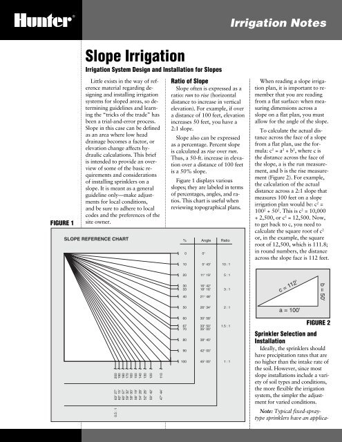
<strong>Irrigation</strong> <strong>Notes</strong>FIGURE 1<strong>Slope</strong> <strong>Irrigation</strong><strong>Irrigation</strong> System Design and Installation for <strong>Slope</strong>sLittle exists in the way of referencematerial regarding designingand installing irrigationsystems for sloped areas, so determiningguidelines and learningthe “tricks of the trade” hasbeen a trial-and-error process.<strong>Slope</strong> in this case can be definedas an area where low headdrainage becomes a factor, orelevation change affects hydrauliccalculations. This briefis intended to provide an overviewof some of the basic requirementsand considerationsof installing sprinklers on aslope. It is meant as a generalguideline only—make adjustmentsfor local conditions,and be sure to adhere to localcodes and the preferences of thesite owner.SLOPE REFERENCE CHARTRatio of <strong>Slope</strong><strong>Slope</strong> often is expressed as aratio: run to rise (horizontaldistance to increase in verticalelevation). For example, if overa distance of 100 feet, elevationincreases 50 feet, you have a2:1 slope.<strong>Slope</strong> also can be expressedas a percentage. Percent slopeis calculated as rise over run.Thus, a 50-ft. increase in elevationover a distance of 100 feetis a 50% slope.Figure 1 displays variousslopes; they are labeled in termsof percentages, angles, and ratios.This chart is useful whenreviewing topographical plans.% Angle Ratio0100°5° 43'10 : 1When reading a slope irrigationplan, it is important to rememberthat you are readingfrom a flat surface: when measuringdimensions across aslope on a flat plan, you mustallow for the angle of the slope.To calculate the actual distanceacross the face of a slopefrom a flat plan, use the formula:c 2 = a 2 + b 2 , where c isthe distance across the face ofthe slope, a is the run measurement,and b is the rise measurement(Figure 2). For example,the calculation of the actualdistance across a 2:1 slope thatmeasures 100 feet on a slopeirrigation plan would be: c 2 =100 2 + 50 2 . This is c 2 = 10,000+ 2,500, or c 2 = 12,500. Now,to get back to c, you need tocalculate the square root of c 2or, in the example, the squareroot of 12,500, which is 111.8;in round numbers, the distanceacross the slope face is 112 feet.2030334011° 19'16° 42'18° 16'21° 48'5 : 13 : 1c = 112'b = 50'5026° 34'2 : 1a = 100'20019018017016015014013063° 27'62° 15'60° 57'59° 32'58° 00'56° 19'54° 28'52° 26'12050° 42'11047° 44'606770809010030° 58'33° 50'35° 00'38° 40'42° 00'45° 00'1.5 : 11 : 1FIGURE 2Sprinkler Selection andInstallationIdeally, the sprinklers shouldhave precipitation rates that areno higher than the intake rate ofthe soil. However, since mostslope installations include a varietyof soil types and conditions,the more flexible the irrigationsystem, the simpler the adjustmentfor varied conditions.0.5 : 1Note: Typical fixed-spraytypesprinklers have an applica-
FIGURE 5for every one percent increasein a slope over ten percent. Forexample, if the slope is 16 percentand the radius of the sprinklersis 50 feet, you would decreasethe spacing by 6 percent,or 3 feet.Additionally, the row of headsclosest to the top row of sprinklerson the slope will throwshort of their desired radius andthe row of heads closest to thebottom row of sprinklers willthrow beyond their desired radius.To correct for this, it isnecessary to shift the interiorrows of sprinklers toward thetop row by the amount that theuphill throw is reduced.These spacing alterations arein addition to any already madeto adjust for wind conditions,relative humidity, or other siterelatedvariables.riser. The HCV can be adjustedsimply by turning a plasticscrew, either through the body,through the shrub base, or afterthe sprinkler head has been removed(see Figure 5).<strong>Hunter</strong> also addresses thelow-head drainage problem bymanufacturing both shrub andpop-up sprinklers that includebuilt-in check valves. For example,the standard checkvalve in the I-20 Ultra will preventdrainage caused by up to10 feet of elevation change.Spring tension seals the rubberwasher against the inlet of thesprinkler until the pressure ofthe water on the seal overcomesthis tension.Pipe InstallationThe main irrigation lineshould be installed at the toe ofthe slope to reduce problems inAll above-ground lateralsshould either be UV-resistantPVC or metal pipe. Lateralpiping should be laid out andinstalled parallel to the slope.Laying pipe parallel to the curbline is unacceptable if there areelevation changes along thecurb line.Staking is required to anchorabove-ground pipe to the slope.Contrary to what you mightthink, the spacing of stakesshould be closer for smaller diameterpipe than for larger pipeto keep the pipe from loopingor drooping. Take into considerationthe weight of the waterin the pipe and place stakes soas to provide enough supportfor that weight.When designing the systemand selecting pipe, be sure totake into consideration pressureloss (or gain) of 0.433 psi perfoot of elevation change. Youmight find it useful to chart thefriction factor for pipe size,based on elevation change,available system pressure, anddistance to the highest head.(Refer to <strong>Hunter</strong> publication<strong>LIT</strong>-083, Calculating DesignCapacity and Working Pressurefor additional information.)Other Components to beConsideredConsideration should begiven to system operating pressure.Lower pressures (below50 psi) increase droplet size,while higher pressures producesmaller droplets which aremore susceptible to wind drift.Avoid pressures that are toolow, as large water droplets cancause soil compaction and leadto increased run-off.If moisture sensors are specified,there should be one installedfor each zone of sprinklers,or at minimum, for eachhorizontal row of laterals.Low-Head DrainageTo eliminate water drainingout of the lowest head in thesystem after each irrigation, acheck valve should be installedon each riser. “Under-head”check valves are available inmany shapes and sizes.Most under-head checkvalves have an adjustment featureso you can adjust theamount of check to compensatefor elevation changes.<strong>Hunter</strong> <strong>Industries</strong> producesan under-head check valve, theHCV, that can be adjustedfrom the outlet port withoutremoving the valve from thethe event of a break in the mainline. If the main line must beinstalled on top of the slope,use metal pipe to reduce thechance of breakage. (The prosand cons of using metal pipehave been discussed in otherpublications.)Install a high-flow/low-pressuredevice at the point of connectionto shut off the flow ofwater in case of a line break.This device should be sized andinstalled according to manufacturer’sguidelines. Be sure theflow capacity of any shut-offdevice is equal to the largestflow demand in the system.
Open granular structure,no evidence of sealingCoarse sandFine sandsFine sandy loamsSilt loamsClay loamsBare GroundGood Soil AggregationHigh Organic ContentBasic Intake Rate:0.75–1.00 in./hr. (19–25 mm/hr)0.50–0.75 in./hr. (13–19 mm/hr)0.35–0.50 in./hr. (9–13 mm/hr)0.25–0.40 in./hr. (6–10 mm/hr)0.10–0.30 in./hr. (3–8 mm/hr)If the main is on top of theslope, spring check valvesshould be installed in the laterallines or directly beloweach sprinkler head to keepwater from draining out of thepipes. Lack of adequate checkcould cause erosion problemsand in severe cases, a vacuumcould be created, causing thepipe to collapse.A master valve should beinstalled at the source to depressurizethe main line oncompletion of each irrigation.Ensure that slope installationshave plenty of flexibility.Although you could zone top,middle and bottom together,that does not allow you to adjustfor increased water requirementsat the top of the slopewhere higher winds and greaterexposure to sunlight will occur.Stretched spacing and overtaxedsystems will only lead toproblems later.Also remember that mostslope installations include a varietyof soil types and conditions.They usually consist of cut andfill, and the more flexible thesystem, the easier it is to adjustfor these varied conditions.The experienced designer willtake prevailing winds, north-vssouth-facingslope, plant types,etc. into consideration duringthe design phase.Note: Be sure you are awareof, and adhere to, local codes,as they vary from area to area.Scheduling ConsiderationsSoil texture alone does notdetermine intake rate, but it canprovide a general idea of approximaterates (most slope installationswill require soil testing,performed by a soil laboratory).Figure 6 can be used todetermine approximate soil intakerates for bare ground.If the sprinkler applicationrates are higher than the soilintake rates, be sure irrigationis scheduled over multiple runtimes. Use the “cycle-andsoak”method of scheduling:apply small amounts of waterin multiple applications, withdelays between the applicationsto allow the water tomove into the soil.Another scheduling considerationis that the lower portionsof the slope will require lessirrigation because they will receivesupplemental water in theform of runoff from the zonesat higher elevations. With highapplication-ratesprinklers, youcan compensate by decreasingindividual run times from thetop to the bottom of the slope.For instance:Top – 30 minutes perrequired irrigation.Middle – 15 minutes perirrigation.Bottom – 15 minutes everyother irrigation.Two bare-soil conditions.UniformTextureNote: Intake rates are dynamic during the irrigation cycle.Bare GroundPoor Soil AggregationLow Organic ContentThin, sealed layer at surfacefollowed by baking andcrackingFor Poor Condition, Reduce by:0.35 in./hr. (9 mm/hr)0.25 in./hr. (6 mm/hr)0.20 in./hr. (5 mm/hr)0.12–0.15 in./hr. (3–4 mm/hr)0.04–0.10 in./hr. (1–3 mm/hr)You also could compensateby lowering the discharge rateof the sprinklers as you movedown the slope.It is important to be sure thatthe maintenance people takingover the system are aware ofthe factors considered duringdesign and installation, particularlythose pertaining to runtimes and application rates.Many times a well-designedand properly installed systembecomes ineffective because ofimproper adjustment over aperiod of time.(Refer to <strong>Hunter</strong> publications:ED-002.B, <strong>Irrigation</strong> Hydraulics,and <strong>LIT</strong>-088, Scheduling<strong>Irrigation</strong> for additionalinformation.)Various sources were consultedwhile preparing thisdocument; contact <strong>Hunter</strong> <strong>Industries</strong>if you desire bibliographicinformation.UniformTextureFIGURE 6<strong>Hunter</strong> <strong>Industries</strong> Incorporated • The <strong>Irrigation</strong> Innovators P/N 7002811940 Diamond St. • San Marcos, California 92069 • U.S.A. • TEL: (1) 760-744-5240 • FAX: (1) 760-744-7461 <strong>LIT</strong>-<strong>095</strong>.PDF 2/99