Mercedes-Benz Vehicle Communication Software Manual [702kb ...
Mercedes-Benz Vehicle Communication Software Manual [702kb ...
Mercedes-Benz Vehicle Communication Software Manual [702kb ...
- No tags were found...

Create successful ePaper yourself
Turn your PDF publications into a flip-book with our unique Google optimized e-Paper software.
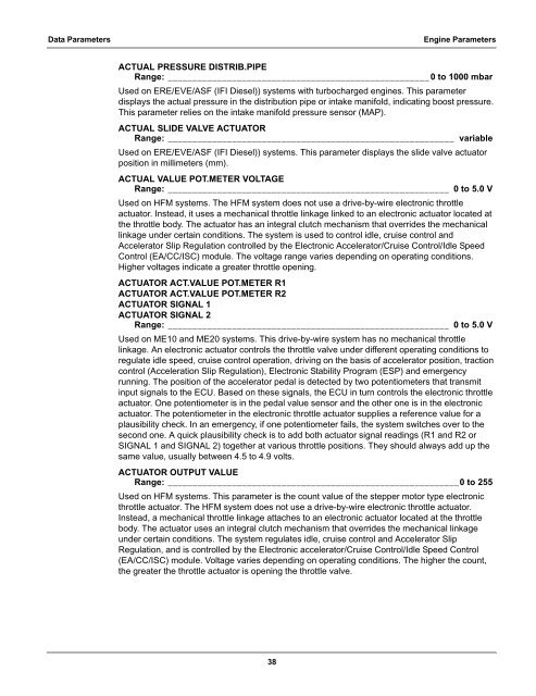
Data ParametersEngine ParametersACTUAL PRESSURE DISTRIB.PIPERange: _____________________________________________________0 to 1000 mbarUsed on ERE/EVE/ASF (IFI Diesel)) systems with turbocharged engines. This parameterdisplays the actual pressure in the distribution pipe or intake manifold, indicating boost pressure.This parameter relies on the intake manifold pressure sensor (MAP).ACTUAL SLIDE VALVE ACTUATORRange: __________________________________________________________variableUsed on ERE/EVE/ASF (IFI Diesel)) systems. This parameter displays the slide valve actuatorposition in millimeters (mm).ACTUAL VALUE POT.METER VOLTAGERange: _________________________________________________________ 0 to 5.0 VUsed on HFM systems. The HFM system does not use a drive-by-wire electronic throttleactuator. Instead, it uses a mechanical throttle linkage linked to an electronic actuator located atthe throttle body. The actuator has an integral clutch mechanism that overrides the mechanicallinkage under certain conditions. The system is used to control idle, cruise control andAccelerator Slip Regulation controlled by the Electronic Accelerator/Cruise Control/Idle SpeedControl (EA/CC/ISC) module. The voltage range varies depending on operating conditions.Higher voltages indicate a greater throttle opening.ACTUATOR ACT.VALUE POT.METER R1ACTUATOR ACT.VALUE POT.METER R2ACTUATOR SIGNAL 1ACTUATOR SIGNAL 2Range: _________________________________________________________ 0 to 5.0 VUsed on ME10 and ME20 systems. This drive-by-wire system has no mechanical throttlelinkage. An electronic actuator controls the throttle valve under different operating conditions toregulate idle speed, cruise control operation, driving on the basis of accelerator position, tractioncontrol (Acceleration Slip Regulation), Electronic Stability Program (ESP) and emergencyrunning. The position of the accelerator pedal is detected by two potentiometers that transmitinput signals to the ECU. Based on these signals, the ECU in turn controls the electronic throttleactuator. One potentiometer is in the pedal value sensor and the other one is in the electronicactuator. The potentiometer in the electronic throttle actuator supplies a reference value for aplausibility check. In an emergency, if one potentiometer fails, the system switches over to thesecond one. A quick plausibility check is to add both actuator signal readings (R1 and R2 orSIGNAL 1 and SIGNAL 2) together at various throttle positions. They should always add up thesame value, usually between 4.5 to 4.9 volts.ACTUATOR OUTPUT VALUERange: ___________________________________________________________0 to 255Used on HFM systems. This parameter is the count value of the stepper motor type electronicthrottle actuator. The HFM system does not use a drive-by-wire electronic throttle actuator.Instead, a mechanical throttle linkage attaches to an electronic actuator located at the throttlebody. The actuator uses an integral clutch mechanism that overrides the mechanical linkageunder certain conditions. The system regulates idle, cruise control and Accelerator SlipRegulation, and is controlled by the Electronic accelerator/Cruise Control/Idle Speed Control(EA/CC/ISC) module. Voltage varies depending on operating conditions. The higher the count,the greater the throttle actuator is opening the throttle valve.38


![BMW Vehicle Communication Software Manual [1198kb PDF File]](https://img.yumpu.com/41822192/1/190x247/bmw-vehicle-communication-software-manual-1198kb-pdf-file.jpg?quality=85)