rotary press trailer system specification - The City of Titusville, Florida
rotary press trailer system specification - The City of Titusville, Florida
rotary press trailer system specification - The City of Titusville, Florida
You also want an ePaper? Increase the reach of your titles
YUMPU automatically turns print PDFs into web optimized ePapers that Google loves.
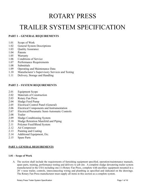
ROTARY PRESSTRAILER SYSTEM SPECIFICATIONPART 1 – GENERAL REQUIREMENTS1.01 Scope <strong>of</strong> Work1.02 General System Descriptions1.03 Quality Assurance1.04 Patents1.05 Warranty1.06 Conditions <strong>of</strong> Service1.07 Performance Requirements1.08 Submittals1.09 Operating and Maintenance Data1.10 Manufacturer’s Supervisory Services and Testing1.11 Delivery, Storage and HandlingPART 2 – SYSTEM REQUIREMENTS2.01 Equipment Scope2.02 Materials <strong>of</strong> Construction2.03 Rotary Fan Press2.04 Sludge Feed Pump2.05 Electrical Control Panel (General)2.06 Electrical Components and Instrumentation2.07 Electrical/Pneumatic Semi-Automatic Controls2.08 Trailer2.09 Sludge Conditioning System2.10 Sludge Retention Manifold and Piping2.11 Polymer Feed/Blend System2.12 Air Com<strong>press</strong>or2.13 Painting and Coating2.14 Additional Equipment, Etc.2.15 Spare PartsPART 1: GENERAL REQUIREMENTS1.01 – Scope <strong>of</strong> WorkA. <strong>The</strong> section shall include the requirements <strong>of</strong> furnishing equipment specified, operation/maintenance manuals,spare parts, training, performance testing and delivery to job site. A complete sludge dewatering <strong>trailer</strong> <strong>system</strong>manufactured in the USA including one (1) Rotary Fan Press, complete with ancillary equipment mounted in a20’ v-nose <strong>trailer</strong>, controls, interconnecting wiring and plumbing as specified and indicated on the drawings.<strong>The</strong> Rotary Fan Press manufacturer must supply all items in this section as a complete <strong>system</strong>.Rotary Press Trailer System Specification Page 1 <strong>of</strong> 16
B. Equipment furnished under the section shall be fabricated, assembled, erected and delivered in full conformitywith the drawings, <strong>specification</strong>s, engineering data, instructions and recommendations <strong>of</strong> the equipment manufacturer,unless exceptions are noted and approved by the engineer prior to installation. Any request for exceptionsto any <strong>specification</strong> and/or stated requirements must be submitted and received a minimum <strong>of</strong> ten (10)working days prior to bid date.C. <strong>The</strong> Rotary Fan Press Trailer System shall be the product <strong>of</strong> a manufacturer regularly engaged in the manufacturingand supply <strong>of</strong> Rotary Fan Press Trailer Systems in the USA. All equipment shall be factory assembledand tested prior to shipment to ensure proper operation <strong>of</strong> all <strong>system</strong>s and be readied for field connections asshown on the project drawings. Any and all parts shall be suitable <strong>of</strong> the intended service conditions, in newcondition and assembled in accordance with the best engineering and shop practices.D. All <strong>of</strong> the equipment specified herein shall be <strong>of</strong>f-loaded, properly stored, and placed in proper operating conditionby the installing contractor in accordance with the engineering data, instructions and recommendation <strong>of</strong>the manufacturer and best construction practices.1.02 – General System DescriptionsConsideration will be given only for pre-approved equipment meeting minimum <strong>system</strong> requirements. <strong>The</strong>Rotary Fan Press Trailer System shall be the model #RFP36D-TR as manufactured by Prime Solution, Inc.<strong>The</strong> contractor will be responsible for any changes necessary to the designs and drawings for any alternateequipment supplied. <strong>The</strong> complete dewatering <strong>system</strong> shall consist <strong>of</strong> one (1) Prime Rotary Fan Press,Ancillary Equipment and Interconnecting Wiring/Plumbing that at a minimum contain:‣ One (1) 20’ Trailer.‣ One (1) Positive Displacement Sludge Feed Pump with VFD Direct Gear Drive Motor.‣ One (1) Emulsion Polymer Feed/Blend System.‣ One (1) PLC Process Controls, Manual and Semi-Auto Operation.‣ One (1) Retention Sludge/Polymer Piping with Adjustable Mixer and Injection Ring.‣ One (1) Rotary Fan Press with Stainless Steel, Hard Chrome Plated Slotted Filer Screens.‣ One (1) Stainless Steel Folding Sludge Cake Conveyor‣ One (1) Air Com<strong>press</strong>or with Receiver.‣ One (1) Central NEMA 4X Electrical Control Panel with Touch Screen Operator Interface.‣ One (1) Standard Workmanship Warranty.‣ Spare Parts Readily Available Within <strong>The</strong> United States <strong>of</strong> America.Consideration for <strong>City</strong> approval <strong>of</strong> another manufacturer not listed above, Vendor shall be required to perform anon-site full scale pilot test, not exceeding thirty (30) days after the bid opening date, demonstrating that theequipment proposed by such Vendor and/or manufacturer is capable <strong>of</strong> meeting the minimum performance requirementsestablished herein.1.03 – Quality AssuranceA. All equipment specified under this section shall be furnished by a single Rotary Fan Press manufacturer locatedin the USA who is fully experienced, reputable and qualified in the production <strong>of</strong> the major equipment items tobe furnished. <strong>The</strong> manufacturer shall be responsible for the sludge dewatering <strong>system</strong> as noted in this <strong>specification</strong>.B. Consideration will be given only to products <strong>of</strong> manufacturers who can demonstrate that their equipment fullycomplies with all requirements <strong>of</strong> the <strong>specification</strong>s, warranties and contract documents. <strong>The</strong> Owner and/or EngineeringFirm, at all times, are the sole judge <strong>of</strong> “Exact Equivalent”, “Approved Alternate” and “Or Equal”designations to the <strong>specification</strong>s.Rotary Press Trailer System Specification Page 2 <strong>of</strong> 16
C. Within five (5) business days <strong>of</strong> the Engineer’s and/or Owners request, the manufacturer shall submit their writtenwarranty coverage for workmanship in meeting the requirements stated in this <strong>specification</strong>.D. All listed and required standards and/or codes shall be met as a minimum requirement and it shall be construedto mean the latest standard, code, <strong>specification</strong> or tentative <strong>specification</strong> adopted and published at the time <strong>of</strong>advertisement for bids.1.04 – Patents<strong>The</strong> manufacturer warrants that the use <strong>of</strong> this <strong>system</strong> and its equipment, in the process for which the <strong>system</strong> hasbeen ex<strong>press</strong>ly designed, will not infringe any U.S. or foreign patents. In the event <strong>of</strong> any claim <strong>of</strong> infringement,the manufacturer shall defend and indemnify the owner free from any liabilities associated with the use <strong>of</strong>the patented equipment or process.<strong>The</strong> manufacturer hereby grants to the owner, in perpetuity, a paid-up license to use any inventions covered bypatent or patents pending, owned or controlled by the manufacturer in the operation <strong>of</strong> the facility being constructedin conjunction with the equipment supplied under this contract, but without the right to grant sublicenses.1.05 – WarrantyA. <strong>The</strong> manufacturer shall warrant, in writing, that all equipment supplied by them shall be free from defects inmaterial and workmanship for a minimum period <strong>of</strong> twelve (12) months from the date <strong>of</strong> approved start-up, notto exceed eighteen (18) months from the date <strong>of</strong> delivery or two thousand-eighty (2,080) operating hours,whichever occurs first unless noted otherwise within this <strong>specification</strong>.B. <strong>The</strong> manufacturer’s warranty shall cover only the replacement and/or repair <strong>of</strong> defective parts if it is establishedto its satisfaction that damage has occurred under normal installation, operation and maintenance conditions andis due to material and/or manufacturing defects.C. All equipment, material and components manufactured by others used in the design <strong>of</strong> the dewatering <strong>system</strong>shall have the same warranty afforded to Prime Solution, Inc. and is subject to and stipulated by the respectivemanufacturer’s warranty provided that the required maintenance has been performed by the Owner.D. Performance <strong>of</strong> the equipment shall be warranted from the manufacturer for meeting the listed material andworkmanship requirements as it relates to the operation/function <strong>of</strong> the equipment furnished in this <strong>specification</strong>.Conditions that affect the performance <strong>of</strong> the equipment furnished that are process/chemistry relatedand/or beyond the scope <strong>of</strong> the equipment supplied shall be the responsibility <strong>of</strong> others and not the equipmentmanufacturer.1.06 – Conditions <strong>of</strong> Service<strong>The</strong> dewatering equipment approved shall be designed to adequately condition and dewater the listed feedsludge within a maximum <strong>of</strong> two (2) dewatering channels per Rotary Fan Press System.Type <strong>of</strong> sludge: ATAD Lime Water Sludge• Feed Solids (% TS) 2.5%-3.5% 1%-5%• Sludge Age (days) 40-60 1-90• Volatile Solids (% TVS) ~70% N/A• Operating Cycle (hrs./day/month) 24/7 3-5 days/month 24/7 12-20 days per monthRotary Press Trailer System Specification Page 3 <strong>of</strong> 16
1.07 – Performance RequirementsA. <strong>The</strong> dewatering <strong>system</strong> shall be capable <strong>of</strong> operating both continuously and intermittently.B. At no time shall it be required to have more than two (2) dewatering channels per Rotary Fan Press System tomeet these Performance Requirements.C. Any changes to Condition <strong>of</strong> Service as listed above that affects the performance <strong>of</strong> the equipment shall be theresponsibility <strong>of</strong> the Owner for any required corrective action to meet these requirements.D. It shall be the responsibility <strong>of</strong> the selected chemical/polymer supplier to furnish the appropriate chemical/polymerfor the manufacturer to meet performance requirements listed above.E. Performance requirements shall not be part <strong>of</strong> any contract and/or performance <strong>of</strong> delivery bond liability andshall be covered by the manufacturer’s written warranty stating all coverage’s and remedies for meeting the performancerequirements <strong>of</strong> the <strong>specification</strong>.1.08 – SubmittalsA. Submit within twenty (20) working days <strong>of</strong> notice to proceed, three (3) copies <strong>of</strong> the following information insufficient detail to demonstrate that the proposed equipment fully meets the requirements <strong>of</strong> the <strong>specification</strong>.Each copy <strong>of</strong> the submittal shall be assembled in one (1) or more loose leaf three (3) ring hard backed binders.Each binder shall be clearly labeled with identifying cover showing project, manufacturer’s name and modelnumber.B. Installation and Storage – Overall drawings showing dimensions, connecting utility sizes, locations and otherpertinent installation data. Recommended storage protection for the equipment furnished.C. Shop Drawings – Dimensional shop and erection drawings for all equipment supplied under this section alongwith all interconnecting components.D. Descriptive Literature – Catalog cut sheets, technical data, performance curves and utility requirements for allequipment supplied under this section.E. Electrical – Detailed wiring diagrams, instrumentation and operational description <strong>of</strong> entire control <strong>system</strong>.F. Operation and Maintenance Instructions – <strong>The</strong>se sections are to be from the complete operation and maintenancemanual as will be provided upon delivery <strong>of</strong> equipment.G. Warranty – Signed warranty. Statements outlining the manufacturer’s ability to timely furnish repairs and servicereplacement parts when and if so required.1.09 – Operating and Maintenance DataA. <strong>The</strong> manufacturer shall provide a total <strong>of</strong> two (2) printed copies and one (1) CD (if specified) per unit specified<strong>of</strong> a complete and comprehensive reference manual containing operating and maintenance data to enable operatorsand plant engineers to correctly operate, service and maintain all equipment and accessories covered by the<strong>specification</strong> and drawings.B. <strong>The</strong> data contained in the manual shall explain and illustrate clearly and simply all principals and theory <strong>of</strong> operation,operating instructions, maintenance procedures, calibration procedures, safety precautions, troubleshootingprocedures, suggested forms for required record keeping, detailed equipment drawings, electrical andinstrumentation schematics.Rotary Press Trailer System Specification Page 4 <strong>of</strong> 16
C. Each copy <strong>of</strong> the manual shall be assembled in one (1) or more loose leaf three (3) ring hard backed binders.Each binder shall be clearly labeled with identifying cover showing project, manufacturer’s name and modelnumber. All composition and printing shall be arranged so that punching does not obliterate any data and eachsection shall be clearly marked. All information on the CD shall be <strong>of</strong> a pdf format.1.10 – Manufacturer’s Supervisory Services and TestingA. <strong>The</strong> Manufacturer shall furnish the services only <strong>of</strong> a qualified factory representative for a minimum period <strong>of</strong>time at the job-site as listed below. Additional services, if requested, shall be available at the manufacturer’slisted portal to portal per diem rate in effect at time <strong>of</strong> delivery <strong>of</strong> service, plus all travel and living expenses.B. Installation:1. A minimum <strong>of</strong> one (1) trip and one (1) day at job-site; a qualified Prime Solution, Inc. representativeshall inspect all supplied equipment <strong>of</strong> the manufacturer for physical damage, correct placement for requiredservice, utility connections and general operation.C. Start-Up:1. <strong>The</strong> equipment manufacturer shall receive two (2) weeks written notice that all installation is completed,representative sludge is available and appropriate chemistry/polymer is on-site prior to arrivingfor start-up by the Owner and/or Contractor.D. Training:2. A minimum <strong>of</strong> three (3) days on-site shall be used to perform equipment and <strong>system</strong> start-up testing andcalibrations to be followed by training and performance testing within the same trip.3. Should the manufacturer’s representative arrive at the job-site and installation is not complete and/orthe appropriate chemistry/polymer is not on-site, the manufacturer shall be allowed to bill the Owner orContractor for the additional time and expense not covered under this <strong>specification</strong>.1. <strong>The</strong> manufacturer shall train the Owners personnel on equipment operation, maintenance and troubleshootingwith a minimum <strong>of</strong> four (4) hours <strong>of</strong> operation manual review and four (4) hours <strong>of</strong> hands onequipment and <strong>system</strong> operation.E. Performance Testing:1. Prior to the Performance/Acceptance Testing, the Owner’s selected chemical/polymer supplier shallperform testing <strong>of</strong> the sludge and supply the required chemistry/polymer for the manufacturer to meetthe performance requirements as listed in this <strong>specification</strong>.2. Testing shall consist <strong>of</strong> test samples taken once per hour and shall be grab samples.3. Samples shall be tested by an approved independent laboratory paid for by the Owner and <strong>of</strong> theOwner’s choosing. All results shall be given directly to the Owner and Manufacturer.4. In the case <strong>of</strong> non-acceptable performance due to the Manufacturer, Owner and/or Chemical/PolymerSupplier.A. Manufacturer – Should the Manufacturer’s equipment supplied per this <strong>specification</strong> be founddefective in meeting the functionality requirements, the Manufacturer shall have sixty (60) daysin which to prove functionality. At its sole expense, supplemental testing and equipment modificationsin order to perform any retest <strong>of</strong> the <strong>system</strong> to meet the requirements listed for the project.Rotary Press Trailer System Specification Page 5 <strong>of</strong> 16
B. Owner – Should the feed sludge be different than the listed data in Section 1.06 and the Ownerwishes to do performance retesting once the feed sludge is as listed in Section 1.06, it shall bethe Owner’s responsibility to make these arrangements with the Manufacturer within sixty (60)days. <strong>The</strong> Owner shall at its sole expense, pay the Manufacturer its standard rate, plus expensesfor the retest <strong>of</strong> the <strong>system</strong>.C. Chemical/Polymer Supplier – Should the chemistry/polymer provided be found not to producea stable, easily released floc <strong>of</strong> the feed sludge where either the dosage rate exceeds <strong>specification</strong>s,capture rates and/or sludge cake solids are lower than listed in the <strong>specification</strong>s, thisshall be the responsibility <strong>of</strong> the Owner and/or Chemical/Polymer Supplier. Should the Ownerrequest that a retest <strong>of</strong> the <strong>system</strong> be performed within sixty (60) days, the Owner shall at itssole expense pay the Manufacturer its standard rate, plus expenses for the retest <strong>of</strong> the <strong>system</strong>.D. Should the Owner, in its opinion, not require any retesting within sixty (60) days, it will automatically<strong>of</strong>ficially accept the performance <strong>of</strong> the <strong>system</strong>.5. Manufactured shall do an onsite demonstration <strong>of</strong> the <strong>system</strong> on both the ATAD Material and water plantresiduals prior to bid.1.11 – Delivery, Storage and HandlingA. <strong>The</strong> Manufacturer will furnish and deliver all equipment, freight prepaid to Owner’s site (Mourning Dove WaterSupply Facility) located at:2836 Garden Street, <strong>Titusville</strong>, FL 32796B. <strong>The</strong> Owner shall be responsible for all <strong>of</strong>f-loading and storage <strong>of</strong> the equipment.Rotary Press Trailer System Specification Page 6 <strong>of</strong> 16
<strong>The</strong> following materials shall be provided for the Rotary Fan Press and related components unless specified otherwiseherein:‣ Housings‣ Frame‣ Filter Plates‣ Filter Plate Supports‣ Center Seal‣ Piping‣ Tubing‣ Discharge Chutes‣ Hardware, Fasteners, Springs,Clips, Etc.Carbon Steel (unless specified as stainless steel)Carbon Steel (unless specified as stainless steel)Stainless Steel and Hard Chrome Plated304 Stainless SteelGlass Filled PolySchedule 80 PVCNylon/PolyStainless SteelStainless Steel2.03 – Rotary Fan PressA. <strong>The</strong> Rotary Fan Press shall be comprised <strong>of</strong> at least the following components:‣ Main Drive System.‣ Two (2) Dewatering Channels, Individually Mounted On Opposing Sides <strong>of</strong> Drive.‣ Filter Wheels and Slotted Elements.‣ Easily Accessible Inspection Windows.‣ HD Support Base.‣ Pneumatically Controlled Restrictor Gates.‣ Internal and External Channel Wash.‣ Cake Discharge Chutes.B. <strong>The</strong> main drive <strong>system</strong> shall be low speed, high torque, helical/bevel foot mounted to the HD epoxy coated steelbase. It shall be fabricated according to ANSI/AGMA 6010 standards with a minimum AGMA standard <strong>of</strong> 9.<strong>The</strong> output shaft shall be made <strong>of</strong> ANSI 17-4 stainless steel or better for maximum service life. <strong>The</strong> incorporateddesign <strong>of</strong> the main drive to the channel housing shall not allow direct contact with the sludge, filtrate orcake at any time. <strong>The</strong> robust construction <strong>of</strong> the main drive shall be used to mount and support the inner channelhousing by bolting to manufacturer’s engineered mounting holes, preventing leakage or gear misalignmentcaused by shaft mounting. Flanged mounted electric drive motor shall be a 3.0 hp, 480 Volt, 3 Phase, 60 Hertztotally enclosed, wash down/VFD rated, high efficiency motor with a minimum service factor <strong>of</strong> 1.15.C. All components <strong>of</strong> the Rotary Fan Press shall be engineered for long, continuous and uninterrupted service. Allfasteners shall be <strong>of</strong> stainless steel and all welding shall be in accordance with the latest applicable codes <strong>of</strong> theAmerican Welding Society. <strong>The</strong> Rotary Fan Press construction shall allow easy access to internal components,operational adjustments, and routine maintenance shall be possible without taking the Rotary Fan Press out <strong>of</strong>service. All servicing <strong>of</strong> the equipment shall be within the building clearances established on the drawings provided.D. Both the inner and outer housing shall be <strong>of</strong> one (1) piece constructed <strong>of</strong> a combination one inch (1”) thick steelring and heavy plate powder coated. <strong>The</strong> outer housing shall have a clear and sealed hinged window for viewingand access to the filter screen outer support for all dewatering channels. <strong>The</strong> channel housings shall containall liquids within themselves and have a three inch (3”) filtrate discharge located in the bottom <strong>of</strong> each side <strong>of</strong>the housings.E. <strong>The</strong> dewatering channels shall have pneumatically adjusted radial seals, to maintain the seal for the outer filtersupport wheel. Any equipment requiring any manual adjustment for the radial seal shall not be considered acceptablefor this application.Rotary Press Trailer System Specification Page 8 <strong>of</strong> 16
F. Each channel shall have an inner and outer filtration element and filter element support made <strong>of</strong> 304 stainlesssteel. <strong>The</strong> filter element supports shall be mounted and attached to the common drive shaft that is directly attachedto the gear reduction drive <strong>of</strong> the Rotary Fan Press. Under maximum loading conditions, the elementsupports shall not have a deflection greater than 0.005” over the entire surface area or require internal bearingsfor support <strong>of</strong> the element support wheels.G. <strong>The</strong> dewatering channel filtration elements shall be constructed <strong>of</strong> two (2) slotted non-clogging filter screenswith supports constructed <strong>of</strong> 304 stainless steel, separated and sealed by a poly-glass filled channel center seal.H. Each <strong>of</strong> the Rotary Fan Press dewatering channels shall have both internal and external filter wash options. <strong>The</strong>wash water time intervals shall be operator directed through the main operator panel. Washing <strong>of</strong> the filter elementsshall be capable <strong>of</strong> being done without interrupting the dewatering process at any time. <strong>The</strong> Rotary FanPress internal filter screen wash requires sixteen (16) gpm at a minimum <strong>of</strong> forty-five (45) psi per channel andthe external filter screen wash requires sixteen (16) gpm at a minimum <strong>of</strong> forty-five (45) psi per channel. <strong>The</strong>incoming water connection shall be 1-1/2” FNPT to the distribution manifold which contain the 110V solenoidoperated valves for controlling the water flow.I. Each dewatering channel shall have a tapered pneumatic adjustable self-compensating glass filled poly sludgecake restrictor gate. With the restrictor gate in its fully open position it shall not restrict the sludge cake openingin any way.J. Individual 304 stainless steel cake discharge chutes shall be provided for each dewatering channel. Each cakedischarge chute shall have an easy to remove inspection cover to gain access to the cake discharge area <strong>of</strong> theRotary Fan Press.2.04 – Sludge Feed PumpA. A positive displacement <strong>rotary</strong> lobe sludge feed pump shall be used to provide adjustable and even feeding <strong>of</strong>the sludge stream to the <strong>press</strong>. <strong>The</strong> sludge feed pump shall be capable <strong>of</strong> supplying 125% <strong>of</strong> the specifiedmaximum speed, not to exceed four hundred-fifty (450) rpm. This combination shall be direct coupled andmounted on one (1) common base and securely fastened to the <strong>trailer</strong> floor. Progressive cavity pumps are notacceptable for this <strong>specification</strong>.1. Rotary Lobe Pump Will Be “Böerger” or Equal.15-120 gpm Under 450 rpm.Suction 3”, Discharge 3”, 150# ANSI Flanged Stainless Steel.Epoxy Coated per Section 2.13.2. Pump Drive Will Be “Nord” or Equal.5 hp with A Min 1.15 sf.Ratio: 4:1Epoxy Coated per Section 2.13.2.05 – Electrical Control Panel (General)A. An electrical control panel shall be furnished with the Rotary Fan Press Trailer System to control the Rotary FanPress functions and those <strong>of</strong> related ancillary equipment specified herein. <strong>The</strong> panel shall be pre-assembled,pre-wired and shall include all controls necessary for semi-automatic and manual <strong>system</strong> operations. <strong>The</strong> panelshall be suitably wired for connection to a 480 Volt, 3 Phase, 60 Hertz power source. A step down transformerprovides 120V AC control power and the DC voltage shall be 24V.B. Wiring shall be accomplished in a neat and organized manner through PVC wire duct, where practical, and tiedsecurely in position with nylon cable ties when not. All <strong>trailer</strong> mounted conduit shall be Schedule 40 PVCand/or non-metallic liquid tight conduit.Rotary Press Trailer System Specification Page 9 <strong>of</strong> 16
C. All electrical components shall be UL or CE recognized and all wiring shall comply with the National ElectricalCode.D. <strong>The</strong> main control enclosure shall house a panel mounted main disconnect with a through the door handle, allmotor starters, variable frequency controls, a programmable logic controller, interlocks, alarms, indicating lightsand touch screen display required for operation <strong>of</strong> the Rotary Fan Press and ancillary equipment described inthis <strong>specification</strong>.E. Shall contain a red mushroom Emergency Stop Button, providing a means <strong>of</strong> quickly stopping all equipmentcontrolled from this panel.F. Motor control is provided by properly sized IEC starters, overloads, VFD’s and individual breakers per each devicerequired.G. <strong>The</strong> Operator Controls and display shall be accomplished by a touch screen, mounted in the door <strong>of</strong> the maincontrol panel. At a minimum, the following control functions shall be located on the touch screen:‣ Feed Pump Speed.‣ Rotary Fan Press Speed.‣ Alarm Silence.‣ Alarm Fault Reset.‣ Aux. Start/Stop.‣ Polymer Water Feed.‣ Screen Contrast.‣ Fault History.‣ Wash Water Selection.‣ Automation Set Points.‣ Polymer System Status.‣ Filtrate Sump.H. All fault and alarms shall be displayed and logged by the touch screen. All faults will stop the Rotary Fan Pressand will need to be cleared to restart the <strong>system</strong>. At a minimum, the following alarms shall be required:‣ Low Polymer Water Pressure.‣ Press Drive Fault.‣ Low Air Pressure.‣ Analog Signal Loss.I. All equipment shall be completely checked out and hot tested prior to shipment. This shall include a test <strong>of</strong> allswitches, lights, relays and other components. All safety devices shall be rechecked completely for operation,function and control prior to final clean-up and packaging for shipment.2.06 – Electrical Components and InstrumentationA. <strong>The</strong> operation <strong>of</strong> the Rotary Fan Press System shall be able to be operated in either manual or semi-automaticmode. <strong>The</strong> <strong>system</strong> shall be able to control flow, <strong>press</strong>ure, conditioning mixing and ancillary equipment listed inthis <strong>specification</strong>. All control functions shall be easily readable and adjusted from the touch screen operatorcontrol panel.B. Bid shall be supplied with the following NEMA 4X rated components: including but not limited to; operatorcontrol panel, touch screen, low water <strong>press</strong>ure switch, <strong>press</strong>ure transducers, flow meter, pneumatic controls andwater solenoids. All skid mounted components shall be wired to the supplied control panel. All wire runs carryingmore than 24 VDC shall be in water tight PVC or PVC coated conduit and/or cabling securely mounted tothe skid. All controls and communication wiring 24 VDC or less shall be jacketed cable, rated for intended use,securely mounted to the skid.Rotary Press Trailer System Specification Page 10 <strong>of</strong> 16
1. Electrical Control Panel Shall Be “H<strong>of</strong>fman” or Equal.Shall Be <strong>of</strong> 304 Stainless Steel with Rounded Edges (molded fiberglass is recognized as equal).Maintaining A NEMA 4X (IP66) Rating.Memory Retaining Door Gaskets.2. <strong>The</strong> PLC Shall Be Manufactured By “Allen Bradley” or Equal.<strong>The</strong> PLC Shall Be An Industrial Grade Programmable Logic Controller.3. Variable Frequency Drives Shall Be ABB. (no substitutions <strong>City</strong> <strong>of</strong> <strong>Titusville</strong> approved Manufacturer)VFD’s Shall Operate with An Output <strong>of</strong> 100% Continuous Capacity without Exceeding <strong>The</strong> MotorsSpecification For Temperature Rise, Full Load Current Draw, Vibration, Noise and Phase Slip.4. Touch Screen Shall Be “Magelis” or Equal.LCD Screen Size: 5.7” Touch Screen.Type: Color.Control and Monitor Operation and Functions <strong>of</strong> <strong>The</strong> Equipment.5. Panel Mounted Fused Disconnect.Rated For 125% <strong>of</strong> <strong>The</strong> Full Load Current.With Through <strong>The</strong> Door Handle.IEC Type: IP65.6. Operation, Pilot Lights, E-Stop and Indicator Lights.NEMA 4X (IP66) Minimum Water Tight and Oil Tight.30.5mm Size, Rated For At Least One (1) Million Cycles.7. Magnetic Type Sludge Flow Meter Shall Be An “Endress + Hauser” or Equal.Hard Rubber Liner, Hastelloy C Electrodes.3” ANSI Flange Connections.316 Stainless Steel Grounding Rings, IP67 Enclosure.8. Electronic Proportional Regulator Shall Be A “Parker”.Signal: 4-20 mA.Suitable For Wash Down: IP65.9. Pressure Transducer Ring Shall Be “Onyx” or Equal.3” PSW Type.Carbon Steel with Acetal End Plates.Buna Sleeve and Silicone Filled.10. Pressure Transducer Shall Be “Ashcr<strong>of</strong>t” or Equal.Pressure Sensing: 0-50 psi.4-20 mA Analog Output.2.07 – Electrical/Pneumatic Semi-Automatic ControlsA. <strong>The</strong> operator has speed control over the Feed Pump, Rotary Fan Press Screen Rotation and Polymer MeteringPump. Pressure set points are adjustable for the Slurry Feed and Restrictor Gates as well as the wash cycles forthe inner and outer channel washes <strong>of</strong> the <strong>press</strong>.B. Each channel shall be independently <strong>press</strong>ure controlled to maintain a balance throughout the process.C. Inlet <strong>press</strong>ure shall be measured by transducers located in the main feed line and the inlet to each dewateringchannel. <strong>The</strong> main inlet <strong>press</strong>ure limits are operator adjustable through the HMI touch screen and are monitoredRotary Press Trailer System Specification Page 11 <strong>of</strong> 16
2.08 – Trailerby the PLC and will trigger appropriate alarms when operating outside the threshold limits. <strong>The</strong> independentchannel <strong>press</strong>ure transducers are also monitored through the PLC and are used to control the electro-pneumaticregulator which in turn controls the operating <strong>press</strong>ure control valve to each channel.A. All equipment including the Rotary Fan Press and ancillary equipment listed within this <strong>specification</strong> shall bemounted in one (1) <strong>trailer</strong> assembly, allowing space and access for any routine maintenance. <strong>The</strong> discharge conveyorslisted shall be included as an integral part <strong>of</strong> the <strong>trailer</strong> Assembly. <strong>The</strong> <strong>trailer</strong> design and constructionshall be <strong>of</strong> an open compact design, allowing for easy maintenance, cleaning and simplicity.1. 20’ V-Nose enclosed <strong>trailer</strong>2 5/8” Hitch ReceiverTwo 8,000 lbs. axels with aluminum wheelsIn floor spare tire compartment with full size spare.In floor stainless steel filtration sumpDouble doors in the rear and a man door on passenger’s sideFloor shall be prepared with spray in liner2.09 – Sludge Conditioning SystemA. Each Rotary Fan Press System shall be provided with a sludge conditioning <strong>system</strong>, designed to make down theproper polymer solution, efficiently mix polymer with the sludge and to adequately flocculate the sludge for optimumdewatering.B. <strong>The</strong> sludge conditioning <strong>system</strong> shall be mounted upstream <strong>of</strong> the <strong>press</strong> and shall consist <strong>of</strong> a flow splittingmanifold, a vortex polymer injection ring and in-line, non-clog, pneumatic variable orifice mixer. Polymer addition<strong>system</strong>s which utilize tanks with mixers or inject polymer directly into the sludge line are not an acceptableequal to the <strong>system</strong> specified due to the excess amounts <strong>of</strong> polymer required by these inefficient <strong>system</strong>s.C. <strong>The</strong> sludge conditioning <strong>system</strong> shall be capable <strong>of</strong> providing the following performances:‣ <strong>The</strong> polymer and sludge must be instantly mixed (less than 1.0 second at 150 gpm).‣ Mixing energy must be pneumatically and independently adjustable during operation.‣ If required, provide a fully open passageway for any solids that may become restricted in the mix valveduring operation to be dislodged.2.10 – Sludge Retention Manifold and PipingA. After the polymer and sludge have been mixed in the sludge conditioning <strong>system</strong>, it will enter the sludge retentionmanifold. This sludge retention manifold will also provide for the sludge feed connection to the Rotary FanPress. <strong>The</strong> sludge retention manifold shall be rigidly mounted to the ceiling using Schedule 80 PVC piping in agentle winding “C” formation to minimize space requirements and provide the required retention time.B. <strong>The</strong> retention manifold shall also include one (1) clear see-through section for visual purposes as well as one (1)sampling port for drawing samples <strong>of</strong> the flocculated sludge during operation.C. Within the sludge retention manifold a pneumatic sludge by-pass valve shall be furnished to divert sludge backto the head <strong>of</strong> the plant for recycle back into the <strong>system</strong>. <strong>The</strong> by-pass also will automatically open should operationalfeed <strong>press</strong>ures exceed the operator control set-point.2.11 – Polymer Feed/Blend SystemRotary Press Trailer System Specification Page 12 <strong>of</strong> 16
A. <strong>The</strong> emulsion polymer feed/blend <strong>system</strong> shall consist <strong>of</strong> an integrated equipment package capable <strong>of</strong> meteringneat polymer, adjusting dilution water rate and meter feeding <strong>of</strong> the activated polymer solution. <strong>The</strong> mechanicalhydrodynamic blending device is specifically designed to dilute and activate emulsion, dispersion and solutiontype polymer with viscosities ranging from 200 to 3,000 cps and active contents up to 50% shall be provided.B. <strong>The</strong> <strong>system</strong> shall, at minimum, include the following components:1. Mechanical Activation/High Shear Mixer Will Be An “Ebara” or Equal.With Modified Mixing Blade and Ring.120 VAC.1-1/4” NPT Suction and 1” NPT Discharge.2. Neat Polymer Metering Pump Head Will Be A “MasterFlex” or Equal.Housing Material: Polyphenlene Sulfide, Acetal, Nylon.Rollers and Bearings: Stainless Steel.3. Neat Polymer Metering Pump Adapter Will Be A “MasterFlex” or Equal.Housing Material: Aluminum.Ratio: 3.7:1.4. Drive Motor Will Be “Weg” or Equal.1/4 hp, 3 Phase, 60 Hz, 1750 rpm.TEFC-IP 55.5. Neat Polymer Check Valve Will Be “LMI” or Equal.Body: PVC.Stainless Steel Ball and Spring.1/2” MNPT and 1/2” Tube Fitting.6. Dilution Water Pressure Reducing Valve Will Be “Watts” or Equal.Body & Cage: Bronze.Seat: <strong>The</strong>rmoplastic.Integral Strainer: Stainless Steel.Diaphragm: Reinforced EPDM.Valve Disc: Elastomer.7. Solenoid Valve.Flow: Up To 125 gpm.NEMA 4X.Temperature: Up To 150° F.8. Dilution Water Rota-Metering Valve Will Be “King Instruments” or Equal.Material: Machined Cast Acrylic.Internal Components: 316I Stainless Steel.1” NPT Brass Connections.Calibration: Conforms To ISA RP 16.6.9. Pressure Gauge.Stainless Steel Liquid Filled.Dial Size: 2-1/2”.Connection Size: 1/4” MNPT.10. Pressure Regulator Will Be A “Parker” or Equal.Rotary Press Trailer System Specification Page 13 <strong>of</strong> 16
Fine Adjustment Sensitivity.Four (4) 1/4” FNPT Gauge Ports.11. Low Water Pressure Switch.Adjustable Set Point: 10-150 psi.1/2” NPT Aluminum.S.P.D.T. SWITCH.12. Air Pressure Switch Will Be “Gems” or Equal.Wetted Parts: Diaphragm Nitrile and Fitting Brass.Pressure: 3.5-100 psi.S.P.D.T. SWITCH.C. Provide an industrial duty differential <strong>press</strong>ure switch sensing loss <strong>of</strong> dilution water <strong>press</strong>ure rated NEMA 4X.On loss <strong>of</strong> dilution water <strong>press</strong>ure, the entire <strong>system</strong> shall shut-down and an alarm will be displayed on the HMItouch screen. Manual restart is required after fault is acknowledged.2.12 – Air Com<strong>press</strong>orA. Air Com<strong>press</strong>or Will Be An “Ingersoll Rand” or Equal.2 hp Single Stage.120V 60Hz.4.5 Gallon Capacity.B. Pneumatic Water Separator Will Be A “Parker” or Equal.1/4” NPT.Five (5) Micron Screen.C. Pneumatic Coalescing Filter Will Be A “Parker” or Equal.1/4” NPT.20 SCFM.Grade 6.D. Pneumatic Auto Blow Down62 Max SCFM At 100 psi.Aluminum Body and Bowl.1/2” NPT.Five (5) Micron.2.13 – Painting and CoatingA. Powder Coat Procedures For Fabricated Parts.1. Near White Sandblasted.2. Primer: Epoxy Powder Three (3) Mils.3. Finish Coat: Powder Coat Five (5) Mils.B. Painting Procedures For Purchased Parts.1. Primer: Bessler Primer.2. Finish Coat: Pitthane Epoxy Paint.C. Electro Polish Procedures For Stainless Steel Fabricated Parts.1. Washed with A Degreaser To Remove All Oil.Rotary Press Trailer System Specification Page 14 <strong>of</strong> 16
2. Deoxidizing Bath To Remove Weld Discoloration and Unify Appearance.3. Electro Polish Bath.D. Hard Chrome Plating For Stainless Steel Filtration Plates.1. Washed with A Degreaser/Thinner To Remove All Oil.2. Industrial Chrome Bath To A Surface Thickness 0.005”.E. Zinc flame spray or hot dip galvanizing <strong>of</strong> any material that is not authentic alloy stainless steel shall not beconsidered an acceptable substitute to this <strong>specification</strong>.2.14 – Additional EquipmentA. 16” Wide Stainless Steel Folding ConveyorB. Filtration Sump Pump Will Be An “Ebara” or Equal.Rotary Press Trailer System Specification Page 15 <strong>of</strong> 16
Rotary Press Trailer System Specification Page 16 <strong>of</strong> 16


