Persistent Memory and Powering UpAny time you change DIP Switches or Software Configuration Settings thataffect parameters the user can change (any filter settings, set temperaturedefault, Celsius vs Fahrenheit, 12-hour vs 24-hour time, reminderssuppression, etc), you must reset Persistent Memory for your DIP Switch orSoftware Configuration Settings changes to take effect. You should also resetPersistent Memory after loading a new file into a board (using the ESM,purchased seperately).To reset Persistent Memory: Power down. Set A12 ON (See illustration below). Power up. Wait until “ ” or “ ” is displayed on your panel.Note: If “ ” appears see section below. Set A12 OFF. (This can be done safely with power on if you use a nonconductivetool such as a pencil to push the switch back to the OFFposition. Otherwise, power down before setting A12 OFF) Power up again (if you powered down in the previous step). For all other power ups, leave A12 OFF.About Persistent Memory and Time of Day Retention:This system uses memory that doesn’t require a battery to store a varietyof settings. What we refer to as Persistent Memory stores all the UserPreferences, as well as all the filter settings, the set temperature, and theheat mode.Persistent Memory is not used for Time of Day. Time of Day needs to be“kept running” (not just stored) while the power is off, so a separate RealTime Clock feature (on all models except the EL1000) keeps track ofTime of Day while the unit is off. Time of Day Retention, and Time of DayRetention alone, is controlled by the J91 jumper. J91 must be set accordingto main system panel used.RTCEnabled(Not Jumpered)Switchbank AJ91RTCDisabled(Jumpered)J91Switchbank Bmessage on power up:If “ ” appears before (and instead of) “ ” or“ ”, you have not configured DIP Switches and/orSoftware Configuration Settings in a valid manner. This must be correctedbefore you can reset Persistent Memory.The switch numbers, jumpers, or configuration settings displayed after“ ” are ones with which the system has found a configuration problem.For example: “” would mean that the combination of how you’ve setA5 and how you’ve set B2 is not supported on this system. “ ” would mean that there is a problem with jumper J99 “ ” would mean that the combination of howyou’ve set pump 3 for 1-speed and blower for 1-speed is not supportedon this system. “ ” would mean that the combination of how you’veset DIP switches which have been assigned to pump 3 and blower is notsupported on this system.Power Up Display SequenceUpon power up, you should see the following on the display: Three numbers in a row, which are the SSID (the System SoftwareID). The third display of these numbers is the Software Version, whichshould match the version of your system. For example, if these threenumbers are , that is a Mach 3 <strong>EL8</strong>000 at version 26. If there is a Configuration Error, the message (see above) willappear at this point (and none of the messages below will display).Otherwise what comes next is: An indication of either the input voltage detected (EL1000/EL2000), orthe heater wattage range supported (<strong>EL8</strong>000/GL2000/GL8000). Heater wattage display: “ ” means the system supports a heaterfrom 1 kW to 3 kW. “ ” means the system supports a heaterfrom 3 kW to 6 kW. “ ” means the system supports a 3 kWheater only. (These ranges may be modified slightly in the case ofspecial heaters, which the next bullet covers.) Input voltage display: A system showing “ ” supports 3 kWto 6 kW heaters. A system showing “ ” supports the very sameheaters, although at 120V those heaters will function at only 1/4 oftheir 240V rated wattage. (The system shows only either “ ” or“ ” as a general indication of input voltage; it does not show theactual input voltage.) If your system is using a special type of heater, a display such as “ ”may appear next. If your system is using the generic <strong>Balboa</strong> heater, noheater type display will appear. “ ” or “ ” will appear to signal the start ofPriming Mode.At this point, the power up sequence is complete. Refer to the User Guidefor the ML Series panel on your system for information about how the spaoperates from this point on.Page 4<strong>55064</strong>-<strong>04</strong>_97_A
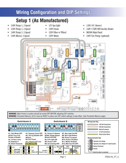
Wiring Configuration and DIP SettingsSetup 1 (As Manufactured) (Stereo) FUSE 30A CLASS GK7BALBOA INSTRUMENTS, INC.MADE IN U.S.A.<strong>EL8</strong>000 Mach 3COPYRIGHT 2006P/N 22<strong>04</strong>1_BF6TORQUERANGEFOR TB1:27-30 IN. LBS.K4J90J13NEUTRALWHITEHOTBLACKHOTREDF7TB1J7W2G NBLK-A120V FiberFUSE 30A CLASS GJ44J49123J12-Spd P1G N12VAC-BWHT AC (120V)J28 J52 J27 J35 J43 J23 J32J26BLK ACW1K5K13J47J66 J65 J68J64 J63 J67J58 J57 J62 J54J95 J46 J74 J75 J53 J55 J59 J60 J56 J61RED AC (240V)321J42J50K11J96J94J48K6W5W3F2K8K3J8Fiber G N Opt.12VAC-BJ9-120V J97BLK-AJ2G NJ30W14J29J25FUSE 1/2A 250V123BARCODEJ14240VTransJ39W6J89F1G NJ92J85321K12-Spd P2J11K12J76K15Circ.PumpG NW4K2J86J3J9G NMisterW7K9K14J93J5G NBLK-A 12VAC-BJ371 2 3W3012V LightREMOTEA.V.J20RTCEnabledJ38J79W8K16J91F5 FUSE 20A 250VJ4K10OzoneG NJ12G NW13F4FUSE 3A 250V2-Spd P3EXP I/OW10J36J69ADCMW15J6W12J10SpaLightNGJ77BlowerG NU4W9J84J21TRC6MAIN PANELS AUX PANELS12 VACJ73 J72 J71 J70J31J16 J34J40J81 J45 J41 J33J51J101HTR2J1005.5 kWHTR1SWITCHBANK ASWITCHBANK BJ22SEN. AJ24SEN. BJ82VACJ19UVTV 2J18 J17 J15 J83TV 1 TST AUX. F CFGWARNING: Main Power to system should be turned OFF BEFORE adjusting DIP switches.WARNING: Persistent Memory (A12) must be RESET to allow new DIP switch settings to take effect. (See Persistent Memory page)A1, Test Mode OFFA2/A3, No Four H.S. H.S.Pumps w/HeaterA4, 12 Hour TimeA5, Degrees FA6, Short Timeouts123J49120V/240VFiber Lightand WheelSwitchbank AJ47A7, Cleanup Cycle OFFA8, 1Hr O3 Disable OFFA9/A10,No Circ PumpA11, Ozone w/P1 lowA12, Memory ONB1, Pump 2 2-SpeedB2/B3, Single SpeedBlower No Blower (On/Off)B4, F/O Light ON OFFB5, Pump 4 OFFB6, Scrunching OFFSwitchbank B3 13 Spa Light RTCJ29J39 J3712V Enabled2 22J9J2 withBlack AC Pump 1 LowJ911 311 2 3B7, Spa Dimmable Light On/Off LightB8, Spa FO & Light Spa Light ButtonB9, Pump 3 2-speedB10, Pump 3 Enabled DisabledB11, Mister Enabled DisabledB12, Mist Aux Pnl OFFPage 5J83SSID #10013432Config SettingsDisabledWiring Color Key120 Volt Connections240 Volt ConnectionsBlack AC Jumpers12 Volt ConnectionsRelay Control WiresBoard Connector Key1 Typically Line voltage2 Typically Line voltage for 2-speed pumps3 Neutral (Common)4 GroundNote flat sides in connector<strong>55064</strong>-<strong>04</strong>_97_A