DIP Switches DefinitionsWARNING:Setting DIP switches incorrectly may cause abnormal system behavior and/or damage to system components.Refer to Switchbank illustration on Wiring Configuration page for correct settings for this system.Contact <strong>Balboa</strong> if you require additional configuration pages added to this tech sheet.DIP Switchbank A KeyA1 ............Test Mode (normally Off)Table 1 # of Hi-SpeedA2 and A3..........Control amp draw requirements. See Table 1Pumps/BlowerA4* ............In“ON” position, displays time in 24 hours (military\European time)Before Heat Disabled............In“OFF” position, displays 12 hour timeA2 A3A5* ............In“ON” position, displays temperature in CelsiusOFF OFF 0............In“OFF” position, displays temperature in Fahrenheit* Sets default for user preferences - only applies when persistent memory is reset (A12 On)ON OFF 1during power-upOFF ON 2A6 ............In“ON” position, Equipment timeout 30 minutes (4 hours for Pump 1 Low) ON ON Up to 4............In“OFF” position, Equipment timeout 15 minutes (2 hours for Pump 1 Low)A7 ............In“ON” position, Cleanup Cycle – 30 minutes after spa use/timeout, Pump 1 Low & Ozone run for 1 hour............In“OFF” position, NO Cleanup CycleA8 ...........In “ON” position, Ozone suppressed for 1 hour after pump or blower button press...........In“OFF” position, NO Ozone suppressionA9 and A10.........Circ Pump Behavior settings. See Table 2Table 2Circ PumpA11 ............In“ON” position (non-circ mode operation) Pump 1 is two-speed, Ozone is ON A9 A10 Behaviorin Filter & Cleanup Cycles only (in any circ mode), Pump 1 is one-speed,OFF OFF No Circ PumpOzone is ON with Circ PumpON OFF 24 Hr............In“OFF” position (non-circ mode operation) Pump 1 is two-speed, Ozone isON with Pump 1 LowOFF ON 24 Hr w/3°F Shut-Off(in any circ mode) Pump 1 is two-speed, Ozone is ON with Circ PumpON ON Acts like Pump 1 LowA12 ............Persistent Memory Reset (used when the spa is powering up)(Filter Cycles, Polls)DIP Switchbank B KeyB1 ...........In“ON” position, single-speed Pump 2...........In“OFF” position, two-speed Pump 2B2 and B3..........Blower Speeds. See Table 3B4 and B8 .........Fiber Optic and Color wheel control; Spa Light EnableNote: The Light button on an ML900 panel is a SpaLight button.The Light button on most other panels is an EitherLight button.B5B6B7 ...........In“ON” position, Spa Light operation is On/Off...........In“OFF” position, Spa Light operation is dimmableB9 ...........In“ON” position, single-speed Pump 3B10B11B12............Pump 4 enable when On. Jets 4 replaces Blower on Aux panel...........In“ON” position, Alternate Panel layout(ML900 scrunching enabled; ML550 and ML700Jets 3 replaces Blower)B4 OFF...........In“OFF” position, Normal Panel layout...........In“OFF” position, two-speed Pump 3...........In“ON” position, Pump 3 enabled (Jets 3 replacesLight button on Aux panel)...........In“OFF” position, Pump 3 disabledB4 ON...........In“ON” position, Mister enabled...........In“OFF” position, Mister disabled...........In“ON” position, Mister or Option replaces Blower button on Aux panels...........In“OFF” position, no button replacement on Aux panelsTable 3B2 B3 Blower SpeedsOFF OFF 0 (No Blower)ON OFF 1 (on/off)OFF ON 2ON ON 3B8 OFFB8 ONNo separately-controlled fiber light; spa light enabled on bothSpaLight and EitherLight buttons; fiber light (not wheel) comes onwith spa light (at any intensity)No separately-controlled spalight; fiber light enabled onboth FiberLight and EitherLightbuttons; spa light comes on withfiber lightSpa light and fiber light eachseparately controlled; fiber lightenabled on both FiberLight andEitherLight buttons; spa lightenabled on SpaLight buttons onlyPage 6<strong>55064</strong>-<strong>04</strong>_97_A
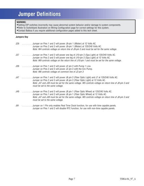
Jumper DefinitionsWARNING:Setting DIP switches incorrectly may cause abnormal system behavior and/or damage to system components.Refer to Switchbank illustration on Wiring Configuration page for correct settings for this system.Contact <strong>Balboa</strong> if you require additional configuration pages added to this tech sheet.Jumpers KeyJ29J37J39J47J49J91.........Jumper on Pins 1 and 2 will power J9-pin 1 (Mister) at 12 Volts AC.Jumper on Pins 2 and 3 will power J9-pin 1 (Mister) at 120/240 Volts AC.Note: W4 controls voltage on return line of J9-pin 3 and must be set for the same voltage..........Jumper on Pins 1 and 2 will power one leg of J10-pin 2 (Spa Light) at 120/240 Volts AC.Jumper on Pins 2 and 3 will power one leg of J10-pin 2 (Spa Light) at 12 Volts AC.Note: W9 controls voltage on the return line of J10-pin 1 and must be set for the same voltage..........Jumper on Pins 1 and 2 will power J2 pin 2 with Pump 1 Low.Jumper on Pins 2 and 3 will power J2 pin 2 with the Circ Pump.Note: W6 controls voltage on common line of J2-pin 3.........Jumper on Pins 1 and 2 will power J8 pin 2 (Fiber Optic Light) and J7 at 120/240 Volts AC.Jumper on Pins 2 and 3 will power J8 pin 2 (Fiber Optic Light) at 12 Volts AC.Note: J47 and J49 must be set for the same voltage. W5 controls voltage on return line of J8-pin 3 andmust be set to the same voltage..........Jumper on Pins 2 and 3 will power J8 pin 1 (Fiber Optic Wheel) at 120/240 Volts AC.Jumper on Pins 1 and 2 will power J8 pin 1 (Fiber Optic Wheel) at 12 Volts AC.Note: J47 and J49 must be set for the same voltage. W5 controls voltage on return line of J8-pin 3 andmust be set to the same voltage..........Jumper on 1 Pin only enables Real Time Clock function, for use with time capable panels.Jumper on Pins 1 and 2 will disable RTC function, for use with non-time capable panels.Page 7<strong>55064</strong>-<strong>04</strong>_97_A