DTC P0110 INTAKE AIR TEMPERATURE ... - Highlander Club
DTC P0110 INTAKE AIR TEMPERATURE ... - Highlander Club
DTC P0110 INTAKE AIR TEMPERATURE ... - Highlander Club

You also want an ePaper? Increase the reach of your titles
YUMPU automatically turns print PDFs into web optimized ePapers that Google loves.
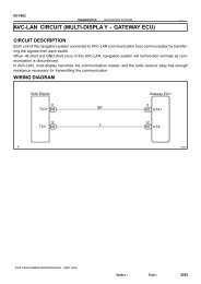
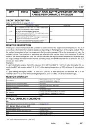
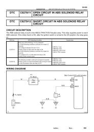
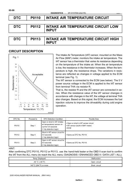
05-90DIAGNOSTICS-SFI SYSTEM (2AZ-FE)0596B-07<strong>DTC</strong> <strong>P0110</strong> <strong>INTAKE</strong> <strong>AIR</strong> <strong>TEMPERATURE</strong> CIRCUIT<strong>DTC</strong> P0112 <strong>INTAKE</strong> <strong>AIR</strong> <strong>TEMPERATURE</strong> CIRCUIT LOWINPUT<strong>DTC</strong> P0113 <strong>INTAKE</strong> <strong>AIR</strong> <strong>TEMPERATURE</strong> CIRCUIT HIGHINPUTCIRCUIT DESCRIPTIONResistance kΩFig. 130201053210.50.30.20.1Acceptable- 20 0 20 40 60 80 100(- 4) 32 68 104 140 176 212Temperature C (F)The Intake Air Temperature (IAT) sensor, mounted on the MassAir Flow (MAF) meter, monitors the intake air temperature. TheIAT sensor has a thermistor that varies its resistance dependingon the temperature of the intake air. When the air temperatureis low, the resistance in the thermistor increases. When the temperatureis high, the resistance drops. The variations in resistanceare reflected as changes in voltage applied to the ECMterminal (see Fig. 1).The IAT sensor is connected to the ECM (see below). The 5 Vpower source voltage in the ECM is applied to the IAT sensorfrom terminal THA via resistor R.That is, the resistor R and the IAT sensor are connected in series.When the resistance value of the IAT sensor changes inaccordance with changes in the IAT, the voltage at terminal THAalso changes. Based on this signal, the ECM increases the fuelinjection volume to improve the driveability during cold engineoperation.A67628<strong>DTC</strong> No. Proceed to <strong>DTC</strong> Detection Condition Trouble Area<strong>P0110</strong> Step 1P0112 Step 4P0113 Step 2Open or short in IAT (Intakeair temperature) sensor circuitfor 0.5 seconds(1 trip detection logic)Short in IAT sensor circuit for0.5 seconds(1 trip detection logic)Open in IAT sensor circuit for0.5 seconds(1 trip detection logic) Open or short in IAT sensor circuit IAT sensor (built-in MAF meter) ECM Same as <strong>DTC</strong> No. <strong>P0110</strong> Same as <strong>DTC</strong> No. <strong>P0110</strong>HINT:After confirming <strong>DTC</strong> <strong>P0110</strong>, P0112 or P0113, use the hand-held tester or the OBD II scan tool to confirmthe IAT from the ALL menu (to reach the ALL menu: DIAGNOSIS / ENHANCED OBD II / DATA LIST / ALL).Temp. DisplayedMalfunction-40 °C (-40°F) Open circuit140°C (284°F) or more Short circuit2005 HIGHLANDER REP<strong>AIR</strong> MANUAL (RM1144U)Author:Date:280
DIAGNOSTICS-SFI SYSTEM (2AZ-FE)05-91MONITOR DESCRIPTIONThe ECM monitors the sensor voltage and uses this value to calculate the intake air temperature. When thesensor output voltage deviates from the normal operating range, the ECM interprets this as a fault in the IATsensor and sets a <strong>DTC</strong>.Example:The sensor voltage output is -40C (-40F), or more than 140C (284F) and either condition continuesfor 0.5 seconds or more.MONITOR STRATEGY<strong>P0110</strong>: IAT sensor range check (Chattering)Related <strong>DTC</strong>sP0112: IAT sensor range check (Low Resistance)P0113: IAT sensor range check (High Resistance)Required sensors / components (Main)IAT sensorRequired sensors / components (Related) -Frequency of operationContinuousDuration0.5 sec.MIL operationImmediateSequence of operationNoneTYPICAL ENABLING CONDITIONSThe monitor will run whenever these <strong>DTC</strong>s are not present See page 05-16TYPICAL MALFUNCTION THRESHOLDS<strong>P0110</strong>:IAT sensor resistanceP0112:IAT sensor resistance [IAT]P0113:IAT sensor resistance [IAT]Less than 98.5 Ω, or more than 156 kΩLess than 98.5 Ω [More than 140C (284F)]More than 156 kΩ [-40C (-40F)]COMPONENT OPERATING RANGEIAT sensor resistance [IAT]98.5 Ω to 156 kΩ [-39 to 140C (-40 to 284F)]2005 HIGHLANDER REP<strong>AIR</strong> MANUAL (RM1144U)Author:Date:281
05-92DIAGNOSTICS-SFI SYSTEM (2AZ-FE)WIRING DIAGRAMM1MAF Meter(IAT Sensor)ECM5 V4L-BShort20E7THAConnector5 G BR5 528BRS28 S29E7E2A90293INSPECTION PROCEDUREHINT: If <strong>DTC</strong>s that are related to different systems are output simultaneously while terminal E2 is used asa ground terminal, terminal E2 may have an open circuit. Read freeze frame data using the hand−held tester or the OBD II scan tool. Freeze frame data recordsthe engine conditions when a malfunction is detected. When troubleshooting, freeze frame data canhelp determine if the vehicle was running or stopped, if the engine was warmed up or not, if the air-fuelratio was lean or rich, and other data from the time the malfunction occurred.(a)(b)(c)1 READ VALUE OF HAND-HELD TESTER OR OBD II SCAN TOOL (<strong>INTAKE</strong> <strong>AIR</strong><strong>TEMPERATURE</strong>)Connect the hand-held tester or the OBD II scan tool to the DLC3.Turn ON the ignition switch. Push the hand-held tester or the OBD II scan tool main switch ON.On the hand-held tester or the OBD II scan tool, enter the following menus: DIAGNOSIS / ENHANCEDOBD II / DATA LIST / ALL / <strong>INTAKE</strong> <strong>AIR</strong>. Read the values.Temperature: The same as actual intake air temperature.Result:DisplayProceed to-40 °C (-40°F) A140°C (284°F) or more BOK (same as present temperature)HINT: If there is an open circuit, the hand-held tester or the OBD II scan tool indicates -40°C (-40°F). If there is a short circuit, the hand-held tester or the OBD II scan tool indicates 140°C (284°F) or more.B Go to step 4CCCHECK FOR INTERMITTENT PROBLEMS(See page 05-9 )A2005 HIGHLANDER REP<strong>AIR</strong> MANUAL (RM1144U)Author:Date:282
DIAGNOSTICS-SFI SYSTEM (2AZ-FE)05-932 READ VALUE OF HAND-HELD TESTER OR OBD II SCAN TOOL (CHECK FOROPEN IN HARNESS)M1MAF MeterECMTHAE2(a)(b)(c)(d)Disconnect the M1 MAF meter connector.Connect terminals THA and E2 of the M1 MAF meter wireharness side connector.Turn the ignition switch ON.On the hand-held tester or the OBD II scan tool, enter thefollowing menus: DIAGNOSIS / ENHANCED OBD II /DATA LIST / ALL / <strong>INTAKE</strong> <strong>AIR</strong>. Read the values.OK:Temperature value: 140°C (284°F) or moreWire Harness SideM1MAF MeterTHAE2YA75743A76903A85506OKREPLACE MASS <strong>AIR</strong> FLOW METER (IAT SEN-SOR)NG3 READ VALUE OF HAND-HELD TESTER OR OBD II SCAN TOOL (CHECK FOROPEN IN ECM)M1MAF MeterTHAE2ECMTHAE2(a) Disconnect the M1 MAF meter connector.(b) Connect terminals THA and E2 of the E7 ECM connector.HINT:Before checking, do a visual and contact pressure check for theECM connector.(c) Turn the ignition switch ON.(d) On the hand-held tester or the OBD II scan tool, enter thefollowing menus: DIAGNOSIS / ENHANCED OBD II /DATA LIST / ALL / <strong>INTAKE</strong> <strong>AIR</strong>. Read the values.OK:Temperature value: 140°C (284°F) or moreYA75742A76903E7ECMA85507OK REP<strong>AIR</strong> OR REPLACE HARNESS ORCONNECTORNG2005 HIGHLANDER REP<strong>AIR</strong> MANUAL (RM1144U)Author:Date:283
05-94DIAGNOSTICS-SFI SYSTEM (2AZ-FE)CONFIRM GOOD CONNECTION AT ECM. IF OK, REPLACE ECM (See page 10-9 )4 READ VALUE OF HAND-HELD TESTER OR OBD II SCAN TOOL (CHECK FORSHORT IN HARNESS)M1MAF MeterECMTHAE2(a)(b)(c)Disconnect the M1 MAF meter connector.Turn the ignition switch ON.On the hand-held tester or the OBD II scan tool, enter thefollowing menus: DIAGNOSIS / ENHANCED OBD II /DATA LIST / ALL / <strong>INTAKE</strong> <strong>AIR</strong>. Read the values.OK:Temperature value: -40°C (-40°F)A75766OKREPLACE MASS <strong>AIR</strong> FLOW METERNG5 READ VALUE OF HAND-HELD TESTER OR OBD II SCAN TOOL (CHECK FORSHORT IN ECM)M1MAF MeterECMTHAE2(a)(b)(c)Disconnect the E7 ECM connector.Turn the ignition switch ON.On the hand-held tester or the OBD II scan tool, enter thefollowing menus: DIAGNOSIS / ENHANCED OBD II /DATA LIST / ALL / <strong>INTAKE</strong> <strong>AIR</strong>. Read the values.OK:Temperature value: -40°C (-40°F)E7ECMYA75744A81699A85508OK REP<strong>AIR</strong> OR REPLACE HARNESS ORCONNECTORNGREPLACE ECM (See page 10-9 )2005 HIGHLANDER REP<strong>AIR</strong> MANUAL (RM1144U)Author:Date:284