Automatic Calibration Method for Driver's Head ... - IEEE Xplore
Automatic Calibration Method for Driver's Head ... - IEEE Xplore
Automatic Calibration Method for Driver's Head ... - IEEE Xplore

Create successful ePaper yourself
Turn your PDF publications into a flip-book with our unique Google optimized e-Paper software.
<strong>IEEE</strong> TRANSACTIONS ON INTELLIGENT TRANSPORTATION SYSTEMS, VOL. 14, NO. 1, MARCH 2013 303<strong>Automatic</strong> <strong>Calibration</strong> <strong>Method</strong> <strong>for</strong> Driver’s <strong>Head</strong>Orientation in Natural Driving EnvironmentXianping Fu, Xiao Guan, Eli Peli, Hongbo Liu, and Gang LuoAbstract—Gaze tracking is crucial <strong>for</strong> studying driver’s attention,detecting fatigue, and improving driver assistance systems,but it is difficult in natural driving environments due to nonuni<strong>for</strong>mand highly variable illumination and large head movements.Traditional calibrations that require subjects to follow calibratorsare very cumbersome to be implemented in daily driving situations.A new automatic calibration method, based on a singlecamera <strong>for</strong> determining the head orientation and which utilizesthe side mirrors, the rear-view mirror, the instrument board,and different zones in the windshield as calibration points, ispresented in this paper. Supported by a self-learning algorithm,the system tracks the head and categorizes the head pose in 12gaze zones based on facial features. The particle filter is used toestimate the head pose to obtain an accurate gaze zone by updatingthe calibration parameters. Experimental results show that, afterseveral hours of driving, the automatic calibration method withoutdriver’s corporation can achieve the same accuracy as a manualcalibration method. The mean error of estimated eye gazes wasless than 5 ◦ in day and night driving.Index Terms—<strong>Calibration</strong>, gaze tracking, head orientation.I. INTRODUCTIONGAZE tracking is crucial <strong>for</strong> studying driver’s attention,detecting fatigue, and improving driver assistance systems.Video-based methods are commonly used in gaze trackingbut are vulnerable to the illumination changes between dayand night. Eye-gaze tracking methods using corneal reflectionwith infrared illumination have been primarily used indoor [1]–[5] but are highly affected by sunlight. Recently, video-basedeye-gaze tracking methods have been used in natural drivingManuscript received March 8, 2012; revised June 5, 2012; acceptedJuly 21, 2012. Date of publication September 21, 2012; date of current versionFebruary 25, 2013. This work was supported in part by the National NaturalScience Foundation of China under Grant 61272368, Grant 60873054, Grant61073056, and Grant 61173035, by the Fundamental Research Funds <strong>for</strong>the Central Universities under Grant 2011QN031, by the Program <strong>for</strong> NewCentury Excellent Talents in University, by the Liaoning Education DepartmentResearch Fund under Grant L2010 061, by the Dalian Science and TechnologyFund under Grant 2010J21DW006, and by the Prevent Blindness InternationalResearch Scholar Award 2010. The work of G. Luo was supported by theNational Institutes of Health (NIH) under Grant AG041974. The work ofE. Peli was supported by the NIH under Grant EY05957. The Associate Editor<strong>for</strong> this paper was S. S. Nedevschi.X. Fu was with the Schepens Eye Research Institute, Harvard MedicalSchool, Boston, MA 02114 USA. He is currently with the In<strong>for</strong>mation Scienceand Technology College, Dalian Maritime University, Dalian 116026, China(e-mail: fxp@dlmu.edu.cn).X. Guan is with Tulane University, New Orleans, LA 70118 USA.E. Peli and G. Luo are with the Schepens Eye Research Institute,Massachusetts Eye and Ear, Harvard Medical School, Boston, MA 02114 USA.H. Liu is with the In<strong>for</strong>mation Science and Technology College, DalianMaritime University, Dalian 116026, China.Color versions of one or more of the figures in this paper are available onlineat http://ieeexplore.ieee.org.Digital Object Identifier 10.1109/TITS.2012.2217377environments [6], [7]. This paper presents an automatic trackingsystem <strong>for</strong> head-pose and eye-gaze estimations in naturaldriving conditions. To achieve this goal, we have developed anovel learning algorithm combined with a particle filter. Thisframework differs from previous methods, to a great extent, inits ability to estimate a driver’s gaze zone automatically, whichminimizes the need <strong>for</strong> driver compliance.The two main contributions of this paper are in the configurationof hardware and designs of algorithms. The firstcontribution is the new learning algorithm that allows <strong>for</strong> theself-classifications of the different head poses and eye gazes.This new algorithm is motivated in part by the work of Toyamaand Blake [8]. We define a set of head poses as a metric spaceand assign those head poses into corresponding gaze zones.Unlike other methods, it does not need to be trained be<strong>for</strong>esystem deployment because the classification process can becompleted and tuned during driving. The self-learning methodis possible based on two reasonable assumptions: 1) when adriver is seated, the driver’s head position relative to the siderear mirrors, the rear-view mirror, the windshield, etc., does notvary greatly and, 2) most drivers have habitual and consistentways of moving their head and eyes when looking in a specificdirection. The learning algorithm is crucial <strong>for</strong> the system’sability to calibrate automatically [9].Our second contribution is the method of combining face detection,a learning algorithm, and particle filtering in a cyclingstructure that enables the tracking system to run automatically.These algorithms are put in a proper logical order so that theycan call each other without manual intervention.Satisfactory accuracy in head-pose and eye location estimationshas been achieved in constrained settings in previousstudies [10], [11]. However, in the absence of frontal faces thatis common in driving, eye locators cannot adequately locate thepupil. While precise gaze direction provides useful in<strong>for</strong>mation,coarse gaze direction is often sufficient, <strong>for</strong> instance, <strong>for</strong> determiningwhether a driver’s attention is off the road ahead sincemost natural eye movements are less than 15 ◦ and a personusually starts moving the head to a com<strong>for</strong>table position be<strong>for</strong>eorienting the eye [12]. Points of interest are grossly delineatedby the head pose. In a meeting situation, <strong>for</strong> instance, the headpose was shown to contribute about 70% of the gaze direction[13]. There<strong>for</strong>e, the head pose is important <strong>for</strong> the estimationof coarse gaze direction, which is called the gaze zone in thispaper. The gaze zone was estimated based on facial features,face location, and face size using a self-learning method andparticle filtering. The system was shown to operate in day andnight conditions and is robust to facial image variation causedby eyeglasses as it does not solely rely on facial feature points,1524-9050/$31.00 © 2012 <strong>IEEE</strong>
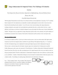
304 <strong>IEEE</strong> TRANSACTIONS ON INTELLIGENT TRANSPORTATION SYSTEMS, VOL. 14, NO. 1, MARCH 2013such as eyes and lip corners, <strong>for</strong> gaze estimation. Because of itslow computation, it can work in real time on a laptop computer.II. RELATED WORKThere are driver gaze tracking methods that consider onlyhead orientations [7]. The size, shape, and distance of facialfeatures and the distance between these features, such as thedistance between the left and right pupils, are used to estimatea driver’s head orientation [14]. The head-pose estimation oftenrequires multiple cameras or complex face models that requireaccurate and lengthy initialization [11]. Although several headposeor eye location methods have shown success in gazeestimation, the underlying assumption of being able to estimategazes based on eye location or the head pose is only valid in alimited number of scenarios [15]–[18].Smith et al. analyzed color and intensity statistics to findboth eyes, lip corners, and the bounding box of the face [19].By using these facial features, they estimated continuous headorientation and gaze direction. However, this method cannotalways find facial features when the driver wears eyeglassesor makes conversation. Kaminski et al. analyzed the intensity,shape, and size properties to detect the pupils, nose bottom, andpupil glints to estimate continuous head orientations and gazedirection [20]. By using the <strong>for</strong>egoing methods consideringboth eye and head orientations, detailed and local gaze directioncan be estimated. However, the accuracy of the eye locationsignificantly drops in the presence of large head movements.This is because, in some cases, the eye structures are notsymmetric; thus, the algorithm delivers poorer per<strong>for</strong>mancewith respect to the distance from the frontal pose.Because errors in facial feature detection greatly affect gazeestimation [12], many researchers measured coarse gaze directionby using only the head orientation with an assumptionthat the coarse gaze direction can be approximated by the headorientation [7]. The methods that only consider head orientationcan be categorized into methods based on shape features withthe eye position, methods based on shape features without theeye position, methods based on texture features, and methodsbased on hybrid (shape and texture) features.<strong>Method</strong>s based on shape features with the eye positionanalyze the geometric configuration of facial features to estimatethe head orientation [14]. These methods rely on preciselocalization of facial features, which is prone to error whenillumination varies and eyeglasses are used in practice. Themethods based on texture features find the driver’s face inthe image and analyze the intensity pattern of the driver’sfacial image to estimate the head orientation. Learning techniquessuch as principal component analysis (PCA), kernelPCA (KPCA), linear discriminant analysis (LDA), and kerneldiscriminate analysis have been used to extract texture features,and these features are then classified to obtain the discrete headorientation [21]. Ma et al. analyzed the asymmetry of the facialimage by using a Fourier trans<strong>for</strong>m to estimate the driver’scontinuous yaw [22]. The methods based on texture features arerelatively reliable because specific facial features do not needto be localized. However, accuracy can degrade when the facedetection module cannot give a consistent result [23]. Wu et al.Fig. 1.Framework of the proposed method.detected the driver’s discrete yaw and pitch by using a coarseto-finestrategy [24]. This method is based on hybrid featurescombining shape and texture features to estimate the headorientation. Murphy-Chutorian et al. estimated the initial headorientation by using a local-gradient-orientation-based (LGO)head orientation method [25], and detailed head orientationwas computed by using a 3-D face model <strong>for</strong> fitting andtracking [26], [27]. This method showed excellent per<strong>for</strong>mancebut required accurate initialization. A general drawback of thehybrid methods is the relatively high computational complexitycaused by combining two feature extraction methods [24].III. PROPOSED GAZE-ZONE ESTIMATION METHODA. Overview of Proposed <strong>Method</strong>This paper presents a combination of face detection [28],self-learning, and particle filtering to build a system <strong>for</strong> drivergaze-zone estimation. The three modules are used <strong>for</strong> detectingdriver’s frontal face, determining the classification of driver’shead orientation, and estimating the current driver’s head poseand moving velocity, respectively. Once face detection is completed,the frontal face of the driver is buffered, and the particlefiltering module calculates the current head pose based on theprevious state and feature selected. Simultaneously, the headposedata are fed into the learning module <strong>for</strong> updating theclassification of head orientations relative to gaze zones. Thereturned results of the particle filtering is utilized to estimatecurrent driver’s gaze zone based on the distance from therepresentatives of the gaze-zone index set and the selectedgaze-zone index. The driver’s head orientation and positionin<strong>for</strong>mation are used to determine the gaze zone. The logicalflowchart of the three algorithms is depicted in Fig. 1.In the face detection step, the face region is located withinthe driver’s entire head image to remove the unnecessarybackground, and the region of the head is used in the following
FU et al.: AUTOMATIC CALIBRATION METHOD FOR DRIVER’S HEAD ORIENTATION 305Fig. 2.Face detection with a bounding box.steps. In addition, the confidence probability is used to representthe accuracy of the head position estimation.To calculate the extremely large head rotation angle, thehead shape and facial features are combined to offer more rawin<strong>for</strong>mation <strong>for</strong> the head position. Facial features are used whenthe frontal face is available. When no frontal face is detected,an appearance-based method is used to track the head position.The head pose provides a coarse indication of gaze that canbe estimated in situations when eyes are not visible (such aslow-resolution imagery, large head rotation angle, and in thepresence of eye-occluding objects such as sunglasses).B. Frontal Face DetectionIt is necessary to detect the driver’s frontal face first sincethe learning algorithm cannot per<strong>for</strong>m correctly if the centercoordinates of the driver’s frontal face are not known. We usedthe frontal face detection method introduced in [28]. The mainadvantages of this method are threefold. The first advantage isits integral image representation, which is the sum of the pixelsvalues above and to the left of a specific location in a 2-Dplane. This is useful <strong>for</strong> calculating Haar-like features rapidlyat any scale. The second advantage is a classifier built uponthe AdaBoost learning algorithm by selecting a few criticalfeatures from a huge number of features extracted with the helpof the integral image. During learning rounds, the examples arereweighted to put emphasis on those incorrectly classified bythe previous weak classifiers that depend on a single feature.Finally, it uses a method where the more complex classifiersare arranged in a cascade structure that drastically reduces thedetecting time by removing unpromising regions. To representthe detecting area, a bounding box is set to enclose the wholeface of the driver, as shown in Fig. 2. After the face region isfound, the background within the box is removed, and the regionof the frontal face is configured <strong>for</strong> facial feature detectionthat is later used as the sample points in the particle filtering.Initially, the face detection is executed repeatedly within a shortperiod of time. Afterward, the center of the bounding boxes ofthe face is used to guide the detection by increasing the weightof those locations. The face detection runs at a regular intervaland modifies the mean center coordinates periodically.As indicated in Fig. 2, simple facial features, such as thecenter of the driver’s face and the left and right borderswithin the bounding box, can be extracted using the method ofOhue et al. [29]. Once these features are determined, a propertrans<strong>for</strong>mation is implemented on the specific area of the rawimages in terms of image patches. Generally, one Gaussian andseveral rotation-invariant Gabor wavelets are applied on theFig. 3. Trans<strong>for</strong>med image-depth image. (a) Mean face when looking at theleft side mirror. (b) First eigenface of (a). (c) Second eigenface of (a). (d) Binaryedge image of (c).Fig. 4. Successful facial feature detection [28] used to enhance the accuracyof gaze estimation is shown as circles marking the lower lip, the nostrils, andthe irises.training patch images extracted from head images. A simpleGabor wavelet is defined by[ψ ω0 ,σ,α(x, y) =exp − 1 ]2σ 2 (˜x2 +ỹ 2 ) cos (2πω 0˜x) (1)where ˜x = x cos (α)y sin (α) and ỹ = x sin (α)+y cos (α).ω 0 denotes the angular frequency, σ is the scale parameter,and α is the orientation of the wavelet. Thus, we obtain therotation-invariant wavelet by integrating a simple wavelet overthe rotation field of α. The distance function on the space A isthe L 2 distance function.Training patches are extracted from head images by locatinga tight bounding box enclosing the head. These patch imagesare resized to 64 × 64 resolution and preprocessed by histogramequalization to reduce the effect of lighting variations.The eigenface and eigenhead images are calculated using thePCA method. Thereafter, Gabor wavelets are applied on theseeigenimages, as defined by (1). The rotation-invariant Gaborwavelets that we used are defined by the scales σ = 1, 2, 4and angular frequencies ω 0 =(1/2), (1/4), (1/8). The resultingimages are sampled at 191 points of a regular grid located insidea reference disk. The trans<strong>for</strong>mations are shown in Fig. 3.In addition, the face detection method (available in OpenCV)in [28] is also used as a supplement when the detection issuccessful, to enhance the accuracy of the eye-gaze estimation.An example of detected facial features using [28] is shownin Fig. 4. When no frontal face is detected, however, theappearance-based method can be used to track the head positioneven when eyes are not visible due to, <strong>for</strong> example, large headrotation and eye-occluding sunglasses (see Fig. 3).The proposed method does not use any head or face modelsince gaze-zone position are trained base on the detectedfeatures. This method has two advantages over other shapefeature-basedmethods. There is no need to train a specific
306 <strong>IEEE</strong> TRANSACTIONS ON INTELLIGENT TRANSPORTATION SYSTEMS, VOL. 14, NO. 1, MARCH 2013model <strong>for</strong> each driver, and it is relatively robust to the wearingof eye glasses or when the head movement is large.C. State ModelThe classification algorithm is based on the true metric space.Given metric space X, the distance function d defined on thisspace satisfies the following three properties: 1) d(x, y) ≥ 0<strong>for</strong> all pairs x, y ∈ X, and d(x, y) =0ifa = b; 2)d(x, y) =d(y, x); and 3) d(x, y)+d(y, z) ≥ d(x, z)In this paper, the driver’s head is modeled as a rigid objectconstrained to 4 ◦ of freedom in the video image plane. Wedefine the state X t =(A t ,v t ), where A t =(T x ,T y ,α t ,β t ) isa 4-D vector consisting of two translations and two rotations(i.e., yaw and pitch), and v t represents the linear and angularvelocities. When looking <strong>for</strong>ward in driving, the driver’s headmotion is normally slow. Only when the driver moves his headcan linear dynamics provide a good temporary approximationof the motion. Thus, we use the mixed state Xt ∗ ,asgivenin[26],with X t =(1 − τ t )X (1)t + τ t X (2)t to represent this situation,and it is defined as follows:X ∗ t =(X t ,τ t ) (2)where ( τ)t is a binary random variable with τ t ∈{0, 1}, X (1)t =1 0X (1)0 0t−1 + ( u (1) )t0denotes the state at time t without( )velocity, and X (2) 1 1t = X (2)0 1t−1 + ( 0)u denotes the constantvelocity. The distribution of τ t depends on the motion of(2)tthe object. Roughly speaking, τ t = 1 whiled(Y t ,Y t−1 ) >ε 1 or d(A t ,A t−1 ) >ε 2where ε 1 and ε 2 are sufficiently small positive numbers; otherwise,τ t = 0. In addition, Y t = T ɛ X t + V t is a realizationof X t provided that T ɛ is a trans<strong>for</strong>mation between the twoimage spaces and that V t is the noise of time point t [8]. Inaddition, the transition density f t (X t |X t−1 ) can be determinedby this state model along with the observation density given byg t (Y t |X t ) ∝ (1/B)exp(−λd(Y t ,T ɛ X t + V t )), where B andλ are normalizing constants. Utilizing the method of particlefilters, the current state X t , which is estimated by a massof sample points assigned with weights, is given by ̂X t =∑ Nn=1 w(n) tcurrent state.˜x (n)t, where ˜x (n)tis the nth sample point of theD. Classification of <strong>Head</strong> OrientationsOur proposed method includes a set of pose-annotated keyframes obtained by using a single camera and a learning algorithmsimilar to that in [8]. The in<strong>for</strong>mation that each key framemaintained is described as follows:M j = {I j ,Z j ,X j }. (3)Provided that X j is the image set of frame j, and I j and Z j arethe intensity and depth images with this image set, respectively.Adopting the learning algorithm, the head-pose key frames aredefined by the following set:M = {M j |1 ≤ j ≤ k}where k is the number of key frames and is determined by thenumber of configured gaze zones. We initialize representativestates <strong>for</strong> each gaze zone by splitting the video image rectangularinto numbers of sectors, which amount to the number ofgaze zones and each of whose center corresponds to the gazezoneindex, based on coordinate’s representations transmittedby the head sensor. To achieve the best result, each imageelement in the incoming frame should be processed, and theseelements then are reorganized to its corresponding gaze-zoneindex set. Once each such set is well defined, the new frame(current) can be approximated by measuring the distance fromeach representative of the gaze-zone index set based on theconditional probability distribution p(M j |M t ), and then a basicframe is chosen to substitute the current frame based on thisprobability distribution so that we can directly determine whichzone the driver is looking at. To make the computation moreefficient, the cardinality of gaze-zone index set #M needs tobe properly small.The exemplar set needs to be determined <strong>for</strong> each driver.Here, A ∗ = {A ∗ i ,i= 1, 2,...k} denotes the final learned result<strong>for</strong> each gaze zone as representations <strong>for</strong> basic frames. Inthis paper, k = 12 as we divide the field of view into 12different gaze zones, and Y = {Y 1 ,Y 2 ,...,Y n } is the imagesequence. When the exemplars are determined from the learningalgorithm, the learned image set is expressed as Y ∗ ={Y0 ∗ ,Y1 ∗ ,...,Yk ∗ }. The learning process is applied at a regulartime interval so that each gaze zone is associated with standardhead poses. In addition, distance functions are defined on theimage space and trans<strong>for</strong>med image space.We constructed a standard data of yaw and pitch based onan inertial head position sensor, which is expressed by A ∗ 0 ={A ∗ 10,A ∗ 20,...,A ∗ k0}. The average distance vector of yaw andpitch between adjacent gaze zones is computed by(α adt ,β adt )= 1 ∑∣ ( T ∗my,pA ∗ i0 − Ty,pAj0)∣ ∗ ∗ ∣(i,j)(ad)provided∑that m counts the adjacent gaze-zone pairs, and(i,j)(ad) |(T y,pA ∗ ∗ i0 − T y,pA ∗ ∗ j0 )| means that only the absolutedifference of adjacent states is counted (ad = adjacent). Inaddition, the notation |·|means that each component of vectorTy,pA ∗ ∗ i0 − T y,pA ∗ ∗ j0 is assigned by its absolute value so that theaverage vector is finally returned.The driver’s gaze zone is analyzed in terms of a probabilityderived from the distance function that measures the yaw andpitch between the given status and each element of a trainedexemplar set (basic frame) A ∗ or Y ∗ .Inwhatfollows,weexploit the mixture centers represented by the estimated yawand pitch <strong>for</strong> each gaze zone.The acquisition of A t <strong>for</strong> each image is based on the particlefiltering algorithm, which will be described in the following.To improve the initial alignment, the first face image is chosensuch thatY 0 = Y0 ∗ =argmin max d(Y,Y ′ ).Y ∈Y Y ′ ∈Y−{Y }
FU et al.: AUTOMATIC CALIBRATION METHOD FOR DRIVER’S HEAD ORIENTATION 307The corresponding state A 0 (first component of X 0 ) is determined,which may be different from the zero point of yaw andpitch.The centers <strong>for</strong> gaze zones are <strong>for</strong>med in such a way inwhich the sequence of A i , associated with image sequence Y i ,is selected to be approximately identical spaced in distance.The base lattice is generated as each point shares the averageyaw deviation ρ y =maxd y (A i ,A j )/y and average pitchdeviation ρ p =maxd p (A i ,A j )/p measured from its adjacentpoint, where d y is the yaw distance, d p is the pitch distance,and A i , A j ∈A. Integers y and p are chosen based on thedistribution of gaze zones. Thereafter, the ratio coefficient vectoris figured out by the <strong>for</strong>mula (c y ,c p )=(α adt /ρ y ,β adt /ρ p )between standard data and samples.Hence, <strong>for</strong> each j, the element of the training set is putinto class j if and only if ‖T y·p A i − Ty,pA ∗ ∗ j0 ‖ is the minimumafter measuring with all elements in A L , where ‖·‖ isthe norm on space {(T y·p A i )}. A quotient set Ā = {A J ,j =1, 2,...,k} is then derived from the classification, and the newrepresentative <strong>for</strong> each element in Ā is determined by A∗ i =arg min A∈Aιmax A ′ ∈A ι \{A} ‖T y·pA − T y·p A ′ )‖. Thus, the finallearning result <strong>for</strong> exemplar set A ∗ = {A ∗ i ,i= 1, 2,...,k}is <strong>for</strong>med. The representing gaze zone of exemplars is denotedby the indicator of exemplar element.The whole learning algorithm is summarized as follows:steps of frontal face detection are also included in the learningstructure. There<strong>for</strong>e, we can achieve the automatic control overthe learning process embedded in the calibrations of headorientations without driver’s collaboration toward specific headposes.E. Particle Filtering <strong>for</strong> State EstimationsWe usually consider only a probability density functiondenoted as p(X). However, in some specific cases, we usenotation P (X) to stand <strong>for</strong> the associated probability distribution(measure). The mathematical expressions adopted in thisalgorithm are consistent with those in [31].Particle filtering is an inference technique that gives anestimation result of an unknown state X t based on a sequencedefof noise observations y 1:t = {y 1 ,y 2 ,...,y t }, which is a realizationof the sequence, arriving in an incremental time step. Inthis paper, we use the state model referred in section E of [31]with Markovian assumptions. The sample states are selectedaccording to the transition density function and the observationdensity function.The evaluation of the transition and observation densitiesis a crucial part of the particle filtering algorithm describedlater as it determines the motion of the object and puts a greatemphasis in the simulation step. The adoption of Monte Carlomethods <strong>for</strong> nonlinear and non-Gaussian filtering dates back tothe pioneering work of [32] and [33] with the aid of importancesampling [34]. Its basic idea comes from the fact that when theanalytic <strong>for</strong>m of the probability density function p(X) or theprobability distribution function P (X) is not available, we mustselect the samples according to an instrumental distributionQ(X) as a substitute <strong>for</strong> the true distribution. Finally, thetrue distribution was approximated by weighing these samplesafter the resampling step is executed, which is helpful <strong>for</strong>determining the best expectation values of specific functionswith variables as the sample points. The details of this algorithmcan be found in [31]. Fig. 5 shows the flowchart.The basic idea of resampling is to select a number fromthe set [N] ={1, 2,...,N} with P (X = i) =w (i)t , and it iseasily comprehended that if we choose N digits from the set[N], the selecting times each digit assigned obey the followingprobability distribution:P (X 1 =(i 1 ,X 2 = i 2 ,X) N = i N )N ( )=w (1) i1(ti 1 i 2 ,...,i Nw (2)t) i2...(w (N)t) iN(4)This learning algorithm runs routinely as all parameters areset up be<strong>for</strong>e the system is initialized. In addition, the repeatedwhere X j = i j . It indicates that the digit j is selected by i jtimes among the N selecting times and that i 1 + i 2 + ···+i N = N. In addition, ( )Ni 1 i 2 ,...,i =(N!/i1N!i 2 ! ...i N !) denotesthe multinomial coefficient. Then, a new particle index set isnaturally constructed as a multiset B = {i 1 · 1,i 2 · 2,...,i N ·N}, with i 1 + i 2 + ···+ i N = N. There exists a one-to-onemap σ from [N] to B, and then we can resample the particlesas x (i)t =˜x (σ(i))t and reset w (i)t =(1/N ). As the unimodalityof the multiplicative decomposition on the right side of (4) wasproven in the combinatorial probability literature in advance,we can thus achieve the best resampling result by searching
308 <strong>IEEE</strong> TRANSACTIONS ON INTELLIGENT TRANSPORTATION SYSTEMS, VOL. 14, NO. 1, MARCH 2013Assign initial importance weights( ) (g 0 y 0 |˜x (i)˜w (i)0 p 00 = ( )q 0 ˜x (i)0 |y 0˜x (i)0end<strong>for</strong> t = 1 : Tif Resampling (condition)Select N particle indices k i ∈{1, 2,...,N}according to the multinomial distribution:(N,w (1)t−1 ,...,w(N) t−1Set x (i)t−1 =˜x(k i)t−1 ,andw(i) t−1 =(1/N ), i = 1,...,NelseSet x (i)t−1 =˜x(i) t−1 , i = 1,...,N.end<strong>for</strong> j = 1 : NPropagate(˜x (j)t ∼ q t X t |x (j)t−1 ,y t˜w (j)tCalculate weight(g t y t |˜x (j)=˜w (j)tt−1endWeight normalizationq t()f t());˜x (j)t)˜x (j)t |x (j)t−1 ,y t|x (j)t−1))Fig. 5.Flowchart of particle filtering.proper values of i 1 ,i 2 ,...,i N that attain such peak. We need topay attention to the fact that the particle ˜w (i)t may be repeatedlysampled in the resampling step. There<strong>for</strong>e, instead of learningall possible calibrations in 2-D space, we propose to automaticallyre-target a set of known points on a target plane to simulatea recalibration each time the driver moves his head. Usingthis new set of known points and the known pose-normalizeddisplacement vectors collected during the calibration phase,it is possible to automatically recalibrate and develop a newmapping.As a result, the indicated gaze zone of the current headpose will be estimated more accurately. Sampling importanceand resampling (SIR) (which is a part of the particle filteringmethod) has made great changes when compared with importancesampling. Our SIR includes the following aspects:1) the overall algorithm can no longer be viewed as a simpleextending of importance sampling because it embeds a repeatedapplication of the importance sampling and resampling; and2) the resampled paths x (i)0:t are dependent on each other. Wesummarize this algorithm as follows.Algorithm 2 Particle FilterInitialization:<strong>for</strong> i = 1 : NSample ˜x (i)0 ∼ q 0 (X 0 |Y 0 = y 0 );endw (i)t=˜w (i)t /N∑m=1Return Êh t(X t )= ∑ N˜w (m)t , m = 1, 2,...,Nn=1 w(n) th t (˜x (n)t );Thus, we obtain the estimated Ât at time point t, and itscorresponding gaze zone is determined by)k =arg j min(Ât d ,A ∗A ∗ j(5)j ∈A∗where d(Ât,A ∗ j ) is an image-based distance metric. The exemplarset is updated at a regular time cycle interval.IV. EXPERIMENTAL RESULTWe use two methods to verify the calculated gaze direction.First, an inertial motion sensor (Colibri made by Trivisio,Germany) was attached on a driver’s head to record the 3-Dhead movement. Second, we recorded testing videos (image resolution:320 by 240 pixels) in which a driver was instructed tolook at given targets. Videos were collected in four driving conditions:daytime, nighttime, wearing glasses, and wearing sunglasses.Video frames from 1 to 500 are used to detect frontalface and determine the center point; frames 501 to 5000 are employedto learn the exemplar element of each gaze zone; the remainingframes are utilized to test the robustness of the system.
FU et al.: AUTOMATIC CALIBRATION METHOD FOR DRIVER’S HEAD ORIENTATION 309TABLE IGAZE-ZONE REPRESENTATIVESFig. 6.Gaze zone <strong>for</strong> calibration and verification in the car.Fig. 7. Gaze zones denoted by the head pose and the eye gaze of imagesplaced at each zone. The lowest face image represents looking at the backwindow.A. System SetupThe gaze-zone estimation system consisted of a monocularcamera mounted at the center of the dashboard pointing to thedriver. To be used in various vehicle environments, includingday and night, the cameras were equipped with an additionalinfrared illumination source that was controlled by an automaticswitch illumination sensor. In daylight, the infrared illuminatoris turned off automatically, and visible light is used to trackfacial features and the head structure. When visible light is tooweak to recognize the face, the infrared illumination turns onautomatically.Facial features are extracted after the face region is detectedusing the method in [28]. As the system does not solely relyon facial features, it can still estimate gaze direction even whenthe detection of some facial features fails. Because of the selflearningalgorithm, the driver’s cooperation <strong>for</strong> this experimentis not needed. Thus, a set of data is chosen randomly to testthe estimation accuracy of the proposed method from about200 000 frames of eight subjects.B. Gaze-Zone EstimationSimilar to the method in [7], the field of view of a driveris partitioned into 12 different gaze zones corresponding tothe two side mirrors, the rear-view mirror, the dashboard, theconsole, the back window, and six zones on the windshield(see Fig. 6). These gaze zones cover most of the possible gazedirections in real-world driving. The typical head-pose image<strong>for</strong> these zones is shown in Fig. 7.The gaze-zone estimation needs to be initialized under acondition in which the zero point of yaw and pitch representsstraight-ahead gaze direction, i.e., gaze zone 7. In this paper,this initialization was per<strong>for</strong>med using the first 500 frames,and the center point was determined by a weighted average ofestimated gaze direction.In our method, yaw and pitch can be accurately evaluated butnot roll; however, they are sufficient <strong>for</strong> gaze-zone estimation.The calculation <strong>for</strong> yaw and pitch depends on the deviatedcoordinates of the center of the bounding box compared withthe coordinate of the frontal face center after the face detectionstep by the following:α = 2 arcsin y d2l ,β = arctan x dlwhere x d and y d represent the row and column deviation fromthe zero point, respectively. l represents the distance from thecenter point of the driver’s face to the rotary axes; there aretwo rotary axes of the driver’s head. The process of frontalface detection will periodically operate to modify the zeropoint of yaw and pitch to enhance the correct rates <strong>for</strong> headposeclassification that is crucial <strong>for</strong> the current gaze-zoneestimation.We collected a standard data set of head poses <strong>for</strong> each gazezone using a head motion sensor (see Table I). For each particulardriver, the video system gradually revises the 12 exemplarsets, and proper elements are assigned to distinct exemplarsets with the highest probability. Typically, the personalizedyaw and pitch values <strong>for</strong> each gaze zone are nearly stabilizedafter about 5000 video frames. In the following tracking, thesystem seeks to estimate head poses and gaze zones by findingthe minimum distance between the previous exemplars and thecurrent sample using (5).Fig. 8 shows the yaw and pitch in the four driving circumstances,i.e., daytime and nighttime, and wearing glasses andwearing sunglasses. The convergence of the curves indicatesthat the driver mostly looked <strong>for</strong>ward after the first couple ofminutes of starting to drive.As the system runs further, the confidence probability increases,as shown in Fig. 9. This helps in confirming the
310 <strong>IEEE</strong> TRANSACTIONS ON INTELLIGENT TRANSPORTATION SYSTEMS, VOL. 14, NO. 1, MARCH 2013TABLE IISTATISTICAL PROPERTIES FOR MEANS OF CONFIDENCE PROBABILITIESFig. 10.Probability distribution of the patronized time of different zones.Fig. 8. Means of (a) yaw and (b) pitch from frames 501 to 9000 in each drivingcondition.Experiment results (see Fig. 11) shows that large errors ofhead motion velocities appeared only in a limited number offrames. In addition, the mean value of the velocity convergesas the number of switch points becomes large, which indicatesgood stability of the driver’s head movement. The value of 1.56is assigned to the velocity threshold up to the current switchpoints <strong>for</strong> which condition. This threshold can be utilized inthe other three conditions, provided that the mean velocityof head movement maintains high stability and consistency.The determination of threshold proceeds automatically whileadopting the learning algorithm, and this value continues to bemodified.Fig. 9. Mean confidence probabilities of head-pose estimation increases alongwith the number of frames in different driving conditions.tracking accuracy. The per<strong>for</strong>mance of the particle filteringgreatly relies on the values of confidence probability, the ratioof matched features, and the total number of features of exemplars.The statistical values <strong>for</strong> confidence probability fromframes 501 to 9000 in four driving conditions are shown inTable II. Although the confidence probabilities <strong>for</strong> the fourdriving conditions are somewhat different, which could be dueto the particle filtering algorithm not fully converging, they aresufficient <strong>for</strong> our application.C. Gaze-Zone StatisticsGaze zone 7 should be patronized in the majority of thetime samples because drivers almost always look <strong>for</strong>ward. Ourexperimental data showed that this is indeed the case. Theprobability distribution of patronized time <strong>for</strong> the gaze zone isdepicted in Fig. 10. The result mainly relies on the classificationin the learning algorithm. Thus, it reflects the per<strong>for</strong>mance ofthe learning algorithm.Fig. 10 also shows that the times (fraction of frames) that thedriver looked at zones 1, 2, 4, 6, and 12 are higher than the timesthe driver looked at other noncenter zones. In other words, thedriver had a relatively higher chance to look at side mirrors, thereview mirror, and the center console.D. Estimation Result Compared With Ground-Truth DataThe motion-sensor ground-truth data were then used to comparewith the head pose computed using our algorithms. Fig. 11shows the tracking errors <strong>for</strong> randomly selected data segmentsas an example. It can be seen that the absolute mean errorsat a steady state of yaw and pitch are about 2 ◦ . Although theerror at the beginning was larger, the rapid convergence ofthese curves indicates the stability of the automatic gaze-zone
FU et al.: AUTOMATIC CALIBRATION METHOD FOR DRIVER’S HEAD ORIENTATION 311TABLE IIISTATISTICAL RESULTS FOR HEAD-POSE AND GAZE-ZONE ESTIMATIONE. Estimation Result Compared With Similar SystemA system that is most similar to our system is describedin [7]. It utilized the ellipsoidal face model to determine thedriver’s yaw angle. A support vector machine was adopted totrain the exemplar set and each of the elements was assigned aspecific gaze zone. The SDRs of our system are almost identicalto their per<strong>for</strong>mance, as shown in [7, Tables V and VII]. Anadvantage of our technique is that our system can operateautomatically, whereas the technique in [7] requires the driver’scooperation in the learning step.Fig. 11. (a) Absolute average error of yaw over four subjects from frames7501 to 9000 in four scenes: daytime, nighttime, wearing glasses, and wearingsunglasses. (b) Absolute average error of pitch from frames 7501 to 9000 infour scenes: daytime, nighttime, wearing glasses, and wearing sunglasses.estimation. It sometimes may take a longer time to reach astable status while the final success detection rate (SDR) is stillhigh. Slow convergence of errors can be resolved by modifyingthe center point and by running the learning algorithm (headposeclassification) more frequently.We achieved high accuracy of head-pose and gaze-zoneestimations. As shown in Table III, the absolute mean error isless than 5 ◦ (with sun glasses) and less than 2.3 ◦ in all otherconditions. This result also serves as a separate evaluation of thelearning algorithm since the per<strong>for</strong>mance of particle filteringhas been estimated by the confidence map. The key to achievinga good result is that the zero coordinate of yaw and pitchare correctly determined, and the classification head poses arecorrect. Although it will generate a small error in selectingthe coordinate system comparing with that created by standarddata, such error is permitted in the overall estimation step. InTable III, we also show the SDR <strong>for</strong> yaw and pitch separately,each of which affects the correct gaze-zone estimation if thevalue of the error exceeds the corresponding threshold (9.5 ◦ and4.5 ◦ <strong>for</strong> yaw and pitch, respectively). The success rate of gazezoneestimation detection ranged from about 90% to nearly100%. When the gaze-zone estimation was wrong, the incorrectselection was always to the adjacent zone.V. C ONCLUSIONWe presented an approach to calibrating the eye gaze in adriving environment which achieved high accuracy of gazezoneestimation while implementing an automatic learningalgorithm and a particle filtering algorithm. This paper demonstratedrobust estimates of the driver’s gaze direction withoutneed of the driver’s cooperation in a calibration process. Thisadvantage makes it suitable <strong>for</strong> wider application in driving research,particularly <strong>for</strong> monitoring driver inattention [35], [36].REFERENCES[1] E. D. Guestrin and M. Eizenman, “General theory of remote gaze estimationusing the pupil center and corneal reflections,” <strong>IEEE</strong> Trans. Biomed.Eng., vol. 53, no. 6, pp. 1124–1133, Jun. 2006.[2] V. Rantanen, T. Vanhala, O. Tuisku, P. Niemenlehto, J. Verho, V. Surakka,M. Juhola, and J. Lekkala, “A wearable, wireless gaze tracker with integratedselection command source <strong>for</strong> human–computer interaction,” <strong>IEEE</strong>Trans. Inf. Technol. Biomed., vol. 15, no. 5, pp. 795–801, Sep. 2011.[3] D. Model, E. D. Guestrin, and M. Eizenman, “An automatic calibrationprocedure <strong>for</strong> remote eye-gaze tracking systems,” in Proc. Annu. Int.Conf. <strong>IEEE</strong> EMBC, 2009, pp. 4751–4754.[4] A. Villanueva and R. Cabeza, “A novel gaze estimation system with onecalibration point,” <strong>IEEE</strong> Trans. Syst., Man, Cybern. B, Cybern., vol. 38,no. 4, pp. 1123–1138, Aug. 2008.[5] C. Ahlstrom, T. Victor, C. Wege, and E. Steinmetz, “Processing ofeye/head-tracking data in large-scale naturalistic driving data sets,” <strong>IEEE</strong>Trans. Intell. Transp. Syst., vol. 13, no. 2, pp. 553–564, Jun. 2012.[6] H. Yang, L. Shao, F. Zheng, L. Wang, and Z. Song, “Recent advancesand trends in visual tracking: A review,” Neurocomputing, vol. 74, no. 18,pp. 3823–3831, Nov. 2011.[7] S. J. Lee, J. Jo, H. G. Jung, K. R. Park, and J. Kim, “Real-time gazeestimator based on driver’s head orientation <strong>for</strong> <strong>for</strong>ward collision warningsystem,” <strong>IEEE</strong> Trans. Intell. Transp. Syst., vol. 12, no. 1, pp. 254–267,Mar. 2011.[8] K. Toyama and A. Blake, “Probabilistic tracking in a metric space,” inProc. Int. Conf. Comput. Vis., 2001, pp. 50–59.[9] A. Doshi and M. M. Trivedi, “Investigating the relationships between gazepatterns, dynamic vehicle surround analysis, and driver intentions,” inProc. <strong>IEEE</strong> Intell. Veh. Symp., 2009, pp. 887–892.[10] B. J. Lance and S. C. Marsella, “The expressive gaze model: Using gaze toexpress emotion,” <strong>IEEE</strong> Comput. Graph. Appl., vol. 30, no. 4, pp. 62–73,Jul./Aug. 2010.
312 <strong>IEEE</strong> TRANSACTIONS ON INTELLIGENT TRANSPORTATION SYSTEMS, VOL. 14, NO. 1, MARCH 2013[11] Z. Zhiwei and J. Qiang, “Novel eye gaze tracking techniques under naturalhead movement,” <strong>IEEE</strong> Trans. Biomed. Eng., vol. 54, no. 12, pp. 2246–2260, Dec. 2007.[12] D. W. Hansen and Q. Ji, “In the eye of the beholder: A survey of models<strong>for</strong> eyes and gaze,” <strong>IEEE</strong> Trans. Pattern Anal. Mach. Intell., vol. 32, no. 3,pp. 478–500, Mar. 2010.[13] R. Stiefelhagen and J. Zhu, “<strong>Head</strong> orientation and gaze direction in meetings,”in Proc. Conf. Human Factors Comput. Syst., 2002, pp. 858–859.[14] R. Valenti, N. Sebe, and T. Gevers, “Combining head pose and eyelocation in<strong>for</strong>mation <strong>for</strong> gaze estimation,” <strong>IEEE</strong> Trans. Image Process.,vol. 21, no. 2, pp. 802–815, Feb. 2012.[15] A. Doshi and M. M. Trivedi, “On the roles of eye gaze and head dynamicsin predicting driver’s intent to change lanes,” <strong>IEEE</strong> Trans. Intell. Transp.Syst., vol. 10, no. 3, pp. 453–462, Sep. 2009.[16] P. Jimenez, J. Nuevo, L. M. Bergasa, and M. A. Sotelo, “Face tracking andpose estimation with automatic three-dimensional model construction,”IET Comput. Vis., vol. 3, no. 2, pp. 93–102, Jun. 2009.[17] K. P. Yao, W. H. Lin, C. Y. Fang, J. M. Wang, S. L. Chang, and S. W. Chen,“Real-time vision-based driver drowsiness/fatigue detection system,” inProc. <strong>IEEE</strong> 71st VTC-Spring, 2010, pp. 1–5.[18] F. I. Kandil, A. Rotter, and M. Lappe, “Car drivers attend to different gazetargets when negotiating closed vs. open bends,” J. Vis., vol. 10, no. 4,pp. 1–11, Apr. 2010.[19] P. Smith, M. Shah, and N. da Vitoria Lobo, “Determining driver visualattention with one camera,” <strong>IEEE</strong> Trans. Intell. Transp. Syst., vol. 4, no. 4,pp. 205–218, Dec. 2003.[20] J. Y. Kaminski, K. D. Knaan, and A. Shavit, “Single image face orientationand gaze detection,” Mach. Vis. Appl., vol. 21, no. 1, pp. 85–98,Oct. 2009.[21] P. Watta, S. Lakshmanan, and H. Yulin, “Nonparametric approaches<strong>for</strong> estimating driver pose,” <strong>IEEE</strong> Trans. Veh. Technol., vol. 56, no. 4,pp. 2028–2041, Jul. 2007.[22] M. Bingpeng, S. Shiguang, C. Xilin, and G. Wen, “<strong>Head</strong> yaw estimationfrom asymmetry of facial appearance,” <strong>IEEE</strong> Trans. Syst., Man, Cybern.B, Cybern., vol. 38, no. 6, pp. 1501–1512, Dec. 2008.[23] E. Murphy-Chutorian and M. M. Trivedi, “<strong>Head</strong> pose estimation in computervision: A survey,” <strong>IEEE</strong> Trans. Pattern Anal. Mach. Intell., vol. 31,no. 4, pp. 607–626, Apr. 2009.[24] J. Wu and M. M. Trivedi, “A two-stage head pose estimation frameworkand evaluation,” Pattern Recognit., vol. 41, no. 3, pp. 1138–1158,Mar. 2008.[25] E. Murphy-Chutorian, A. Doshi, and M. M. Trivedi, “<strong>Head</strong> pose estimation<strong>for</strong> driver assistance systems: A robust algorithm and experimentalevaluation,” in Proc. <strong>IEEE</strong> Conf. Intell. Transp. Syst., 2007, pp. 709–714.[26] E. Murphy-Chutorian and M. M. Trivedi, “HyHOPE: Hybrid head orientationand position estimation <strong>for</strong> vision-based driver head tracking,” inProc. <strong>IEEE</strong> Intell. Veh. Symp., 2008, pp. 512–517.[27] E. Murphy-Chutorian and M. M. Trivedi, “<strong>Head</strong> pose estimation andaugmented reality tracking: An integrated system and evaluation <strong>for</strong> monitoringdriver awareness,” <strong>IEEE</strong> Trans. Intell. Transp. Syst., vol. 11, no. 2,pp. 300–311, Jun. 2010.[28] P. Viola and M. Jones, “Robust real-time face detection,” Int. J. Comput.Vis., vol. 57, no. 2, pp. 137–154, May 2004.[29] K. Ohue, Y. Yamada, S. Uozumi, S. Tokoro, and A. Hattori, “Developmentof a new pre-crash safety system,” presented at the SAE World Congr.Exhibition, Detroit, MI, 2006, SAE Tech. Paper 2006-01-1461.[30] W. Rudin, Functional Analysis. New York: McGraw-Hill Science,1991.[31] O. Cappe, S. J. Godsill, and E. Moulines, “An overview of existing methodsand recent advances in sequential Monte Carlo,” Proc. <strong>IEEE</strong>, vol. 95,no. 5, pp. 899–924, May 2007.[32] J. Handschin and D. Mayne, “Monte Carlo techniques to estimate theconditional expectation in multi-stage non-linear filtering,” Int. J. Control,vol. 9, no. 5, pp. 547–559, 1969.[33] J. Handschin, “Monte Carlo techniques <strong>for</strong> prediction and filtering ofnon-linear stochastic processes,” <strong>Automatic</strong>a, vol. 6, no. 4, pp. 555–563,Jul. 1970.[34] N. Gordon, D. Salmond, and A. F. Smith, “Novel approach tononlinear/non-Gaussain Bayesian state estimation,” Proc. Inst. Elect.Eng.—Radar Signal Process., vol. 140, no. 2, pp. 107–113, Apr. 1993.[35] D. Yanchao, H. Zhencheng, K. Uchimura, and N. Murayama, “Driverinattention monitoring system <strong>for</strong> intelligent vehicles: A review,” <strong>IEEE</strong>Trans. Intell. Transp. Syst., vol. 12, no. 2, pp. 596–614, Jun. 2011.[36] M. Wollmer, C. Blaschke, T. Schindl, B. Schuller, B. Farber, S. Mayer,and B. Trefflich, “Online driver distraction detection using long short-termmemory,” <strong>IEEE</strong> Trans. Intell. Transp. Syst., vol. 12, no. 2, pp. 574–582,Jun. 2011.Xianping Fu received the Ph.D. degree in communicationand in<strong>for</strong>mation system from Dalian MaritimeUniversity, Dalian, China, in 2005.From 2008 to 2009, he was a Postdoctoral Fellowwith Schepens Eye Research Institute, HarvardMedical School, Boston, MA. He is currently aProfessor with In<strong>for</strong>mation Science and TechnologyCollege, Dalian Maritime University. His researchinterests include perception of natural scenes in engineeringsystems, including multimedia, image/videoprocessing, and object recognition.Xiao Guan received the B.S. degree in mathematicsfrom Dalian Maritime University, Dalian, China, in2012. He is currently working toward the Ph.D.degree in mathematics with Tulane University, NewOrleans, LA.Eli Peli received the B.S.E.E. and M.S.E.E. degreesfrom the Technion-Israel Institute of Technology,Haifa, Israel, and the O.D. degree from the NewEngland College of Optometry, Boston, MA.He is currently a Moakley Scholar in aging eyeresearch, a Co-director of Research with SchepensEye Research Institute, and a Professor of Ophthalmologywith Harvard Medical School, Boston,MA. He is also a faculty member with the NewEngland College of Optometry and Tufts UniversitySchool of Medicine. His research interests includeimage processing in relation to visual function and clinical psychophysics inlow-vision rehabilitation, image understanding, evaluation of display–visioninteraction, and oculomotor control and binocular vision.Dr. Peli is a Fellow of the American Academy of Optometry, the OpticalSociety of America, the International Society of Optical Engineering, and theSociety <strong>for</strong> In<strong>for</strong>mation Display. He is currently an Associate Editor <strong>for</strong> the<strong>IEEE</strong> TRANSACTIONS ON IMAGE PROCESSING.Hongbo Liu received the Ph.D. degree in computerscience from Dalian University of Technology,Dalian, China.He is currently a Professor with the In<strong>for</strong>mationScience and Technology College, Dalian MaritimeUniversity, Dalian. In the last several years, he hasbeen engaged in research and teachings on designand analysis of computer algorithms, agent systems,intelligent robotics, brain and cognition, etc. Hisresearch interests include system modeling and optimizationinvolving soft computing, probabilisticmodeling, cognitive computing, machine learning, data mining, etc.Dr. Liu actively participates and organizes international conferences andworkshops.Gang Luo received the Ph.D. degree fromChongqing University, Chongqing, China, in 1997.He is currently an Assistant Professor withHarvard Medical School, Boston, MA. He has beenworking in the fields of image processing and optics.His research interests include vision science.Dr. Luo has been a Peer Reviewer <strong>for</strong> multiplejournals across engineering and vision science.