In-the-Spectacle-Lens Telescopic Device for Low Vision
In-the-Spectacle-Lens Telescopic Device for Low Vision
In-the-Spectacle-Lens Telescopic Device for Low Vision

Create successful ePaper yourself
Turn your PDF publications into a flip-book with our unique Google optimized e-Paper software.
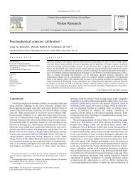
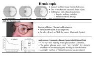
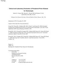
of an object toge<strong>the</strong>r with <strong>the</strong> unmagnified image of <strong>the</strong> rest of <strong>the</strong> scene except <strong>for</strong> <strong>the</strong> ringscotoma (Fig. 2a). With a small FOV, a telescope that is misaligned with <strong>the</strong> eye’s optical axiscan present a magnified image of an object immediately above <strong>the</strong> view of <strong>the</strong> same objectthrough <strong>the</strong> carrier lens (Fig. 2b). This method of dealing with <strong>the</strong> ring scotoma of <strong>the</strong> bioptictelescope was termed ‘Simulvision’ and was described with <strong>the</strong> introduction of <strong>the</strong> bi-leveltelemicroscopic apparatus (BITA) micro Galilean bioptic telescope 35 . Simulvision is anexample of spatial multiplexing by shifting 6 .abFigure 2: A simulated view of a road sign viewed through a 3× telescope. a)The view through a conventional bioptic. The magnified image on <strong>the</strong> retinablocks <strong>the</strong> view of much of <strong>the</strong> intersection creating a ring scotoma (blindarea). b) The rectangular field-of-view through <strong>the</strong> in-<strong>the</strong>-lens telescope.The magnified image is shifted up blocking part of <strong>the</strong> view of <strong>the</strong> overheadpedestrian bridge but leaves <strong>the</strong> intersection in full view. Note <strong>the</strong> nonmagnifiedview of <strong>the</strong> road sign seen under <strong>the</strong> magnified view. The whiteline surrounding <strong>the</strong> magnified image is only added to make <strong>the</strong> illustrationclearer.6
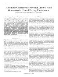
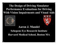
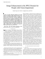
M1M2tabcFigure 3: a) A basic schematic design of <strong>the</strong> in-<strong>the</strong>-lens telescope with a spectaclelens of thickness, t, seen from above. For <strong>the</strong> Galilean design a positive objectivelens and a negative ocular lens are laminated to <strong>the</strong> carrier lens. Two mirrors serveto periscopically pass <strong>the</strong> image from <strong>the</strong> objective to <strong>the</strong> ocular. b) An illustration of<strong>the</strong> in-<strong>the</strong>-lens when <strong>the</strong> wearer looks though <strong>the</strong> carrier lens. c) The same lensfollowing a head tilt that brings <strong>the</strong> telescope in front of <strong>the</strong> pupil. Note <strong>the</strong> thin and tallshape of <strong>the</strong> telescopic mirrors due to <strong>the</strong> limitation imposed by <strong>the</strong> carrier lensthickness on <strong>the</strong> width of <strong>the</strong> mirrors.The most important design parameter <strong>for</strong> a bioptic telescope is <strong>the</strong> magnification. Bioptictelescopes range in magnification from 1.5× to 8×, with 3× to 4× used most commonly. Theangular magnification M of an afocal Galilean telescope, as shown in Fig. 3, is determined by <strong>the</strong>ratio of <strong>the</strong> object focal length of <strong>the</strong> objective lens f ob (negative in this case) to <strong>the</strong> image focallength of <strong>the</strong> ocular lens f' oc (also negative since <strong>the</strong> ocular is divergent):Mff ′ob= . (1)oc<strong>In</strong> <strong>the</strong> case of a Galilean telescope M is positive, meaning <strong>the</strong> final image is erect (not inverted).8
The afocal condition is achieved when <strong>the</strong> distance between objective and ocular lenses,called tube length L, is equal to <strong>the</strong> difference of <strong>the</strong> focal lengths of both lenses. <strong>In</strong> thisembedded design, light travels through <strong>the</strong> carrier lens of refractive index n. Under <strong>the</strong> thin-lensapproximation, it is generally derived as:obocoboc( − M ) f ocL = f ′ − f = −nf+ nf ′ = n 1 ′ . (2)Attending to <strong>the</strong> sign of focal lengths in <strong>the</strong> case of <strong>the</strong> Galilean telescope, it results as:( M − ) focL = n 1 ′ . (3)The second most important parameter <strong>for</strong> a bioptic telescope is <strong>the</strong> field-of-view (FOV).Ei<strong>the</strong>r <strong>the</strong> objective or <strong>the</strong> ocular may serve as <strong>the</strong> limiting aperture in a Galilean telescope. TheFOV, on <strong>the</strong> retina of <strong>the</strong> wearer, is determined by ei<strong>the</strong>r <strong>the</strong> angle spanned at <strong>the</strong> pupil by <strong>the</strong>ocular lens or <strong>the</strong> angle spanned by <strong>the</strong> image of <strong>the</strong> objective as seen through <strong>the</strong> ocular; <strong>the</strong>smaller of <strong>the</strong>se two angles is <strong>the</strong> FOV. <strong>In</strong> <strong>the</strong> design of <strong>the</strong> Galilean telescope shown in Fig. 3a,<strong>the</strong> carrier lens thickness limits <strong>the</strong> periscopic mirrors’ width but not <strong>the</strong>ir height. Since wewould like to keep <strong>the</strong> carrier lens as thin as practical <strong>for</strong> cosmetic and weight considerations,<strong>the</strong> field of such a telescope is likely to be taller than it is wide (Fig. 3b). This is less thanoptimal as <strong>the</strong> width of <strong>the</strong> FOV is considered more important <strong>for</strong> bioptics than <strong>the</strong> height. <strong>In</strong>addition, <strong>the</strong> exit pupil, <strong>the</strong> image of <strong>the</strong> objective <strong>for</strong>med by <strong>the</strong> ocular, is smaller than <strong>the</strong>objective itself, since <strong>the</strong> lateral magnification is 1/M.The second factor affecting <strong>the</strong> FOV is <strong>the</strong> distance between <strong>the</strong> field-limiting apertureand <strong>the</strong> eye’s pupil. Since <strong>the</strong> device is meant to be embedded in a spectacle lens, <strong>the</strong> distancefrom <strong>the</strong> last optical surface to <strong>the</strong> eye should be as similar as possible to that of conventionalspectacle ophthalmic lenses. This vertex distance is usually 12 to 14mm 37 . <strong>In</strong> <strong>the</strong> case of <strong>the</strong>Galilean design <strong>the</strong> exit pupil of <strong>the</strong> telescope lies within <strong>the</strong> telescope. Generally, <strong>the</strong> exit pupilacts as a field-limiting aperture and, since <strong>the</strong> eye can never be placed in <strong>the</strong> same plane, it limits9
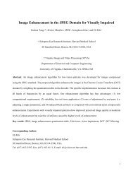
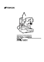
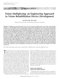
dimension). The FOV of a Keplerian telescope is limited only by <strong>the</strong> size of <strong>the</strong> ocular lens.Thus <strong>the</strong> Keplerian design in-<strong>the</strong>-lens telescope has an added advantage that <strong>the</strong> width of <strong>the</strong>FOV may be large even with a fairly thin carrier lens. Only <strong>the</strong> height of <strong>the</strong> FOV is limited by<strong>the</strong> thickness of <strong>the</strong> carrier.ObjectiveM1OcularM1M4M4M3M2M3M2tabFigure 4: a) Side view schematic of <strong>the</strong> Keplerian design in-<strong>the</strong>-lens telescope withlaminated lenses and four flat erecting mirrors. b) Front view illustration of <strong>the</strong>Keplerian design telescope that emphasizes <strong>the</strong> wide but short configuration of <strong>the</strong>mirrors and <strong>the</strong> corresponding FOV. <strong>In</strong> this design <strong>the</strong> carrier lens thickness limits <strong>the</strong>height but not <strong>the</strong> width of <strong>the</strong> objective and ocular mirrors.With <strong>the</strong> Keplerian design, <strong>the</strong> eye relief is positive and <strong>the</strong> exit pupil is outside <strong>the</strong>telescope, allowing <strong>the</strong> eye pupil to be conjugated with <strong>the</strong> exit pupil. There<strong>for</strong>e <strong>the</strong> field limitingaperture is now <strong>the</strong> ocular. This is better than <strong>the</strong> Galiean design in two ways. First, <strong>the</strong> distancefrom <strong>the</strong> aperture to <strong>the</strong> eye is reduced (increasing <strong>the</strong> angular span of <strong>the</strong> field), and second, <strong>the</strong>dimension of <strong>the</strong> limiting aperture (<strong>the</strong> ocular itself) is not affected by <strong>the</strong> magnification.The Keplerian design also lends itself well to Simulvision. Tilting mirror M4 (in Fig. 4a)a few degrees clockwise will shift <strong>the</strong> magnified image up, as illustrated in Fig. 2b. An angulardisplacement upward of T° can be achieved by tilting <strong>the</strong> M4 mirror (½T°). This provides <strong>the</strong>11
wearer an unobstructed, non-magnified view of <strong>the</strong> environment through <strong>the</strong> carrier lens at <strong>the</strong>same time as a magnified image (through <strong>the</strong> telescope) that is translated vertically, enabling anopen, wide horizontal FOV including that of objects seen through <strong>the</strong> telescope. The magnifiedimage could be shifted in o<strong>the</strong>r directions, but shifting <strong>the</strong> magnified image above <strong>the</strong>unmagnified view is preferable because <strong>the</strong> magnified image occupies an area of <strong>the</strong> visual fieldthat is less likely to include obstacles or o<strong>the</strong>r mobility relevant objects. The in-<strong>the</strong>-lens telescopedesign facilitates Simulvision, in part, because <strong>the</strong>re is no opaque frame or mounting structure toblock <strong>the</strong> unmagnified view.The optical elements that act as objective and ocular lenses can be conventional meniscuslenses attached to <strong>the</strong> carrier lens as shown in Figs. 3 and 4. However, those lenses could bereplaced with curved mirrors, Fresnel lenses, diffractive lenses, or holographic elements. Theseo<strong>the</strong>r elements have a durability advantage as <strong>the</strong>y can be embedded within <strong>the</strong> carrier lens.Curved mirrors also offer several o<strong>the</strong>r important benefits: mirrors are free of chromaticaberration; <strong>the</strong>y yield more optical power with <strong>the</strong> same curvature when compared with planoconvexlenses (thus reducing <strong>the</strong> dimension requirements <strong>for</strong> <strong>the</strong> carrier lens); and <strong>the</strong> distancebetween mirrors needed to create an afocal optical system does not depend on <strong>the</strong> refractiveindex of <strong>the</strong> carrier lens, but only on <strong>the</strong>ir focal lengths.2.3. Keplerian prototype with laminated lenses<strong>In</strong> a first prototype we implemented <strong>the</strong> generic design described in section 2.2 (shown inFig. 4). The lower image erecting mirrors were made by cutting an ophthalmic lens blank and<strong>the</strong> periscopic mirrors were created using small prisms. All mirroring was achieved in this designthrough total internal reflection, as shown in Fig. 5.12
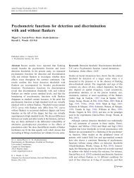
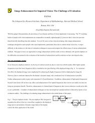
Figure 8: An astronomical Keplerian prototype telescope constructed from two 90° offaxisparabolic mirrors.aBFigure 9: The view through <strong>the</strong> 2× astronomical Keplerian telescope created with two90° off-axis parabolic mirrors. a) A view of a building across <strong>the</strong> street. b) The view of<strong>the</strong> same building through <strong>the</strong> telescope showing a clear magnified inverted image of<strong>the</strong> crane and significant distortion in one meridian. The color of <strong>the</strong> image is a resultof <strong>the</strong> gold coating of <strong>the</strong> mirrors.2.6. Keplerian design with beam splittersAn alternative design <strong>for</strong> a fully embedded Keplerian in-<strong>the</strong>-lens telescope without <strong>the</strong>distortion uses two assemblies of beam splitters in combination with spherical concave mirrors toobtain <strong>the</strong> optical power and <strong>the</strong> periscopic mirror effects as shown in Fig. 10. This approach16
implements a magnifying element similar to that used in <strong>the</strong> in-<strong>the</strong>-lens electronic displaydeveloped by MicroOptical Engineering Corp 39 . Light entering <strong>the</strong> carrier lens at <strong>the</strong> objectivewindow on <strong>the</strong> left (Fig. 10) is reflected by <strong>the</strong> first beam splitter towards <strong>the</strong> concave mirror to<strong>the</strong> left (<strong>the</strong> objective). Following reflection and convergence at <strong>the</strong> concave mirror <strong>the</strong> lightpasses to <strong>the</strong> right through <strong>the</strong> beam splitter traveling through <strong>the</strong> carrier lens, <strong>for</strong>ming anintermediate image plane, and proceeding through <strong>the</strong> second beam splitter. It reflects off <strong>the</strong>second spherical concave mirror (<strong>the</strong> ocular), and is <strong>the</strong>n reflected by <strong>the</strong> second beam splitterinto <strong>the</strong> wearer’s eye. This arrangement provides a Keplerian (astronomical, reversing) telescopewith significant light loss due to <strong>the</strong> 4 passes through <strong>the</strong> beam splitters. Four such passes willresult in loss of 15/16 (94%) of <strong>the</strong> entering light.Quarter-wavePlate (λ/4)PolarizingbeamQuarter-wavePlate (λ/4)tPlano Convex lensBack side mirroredCarrier lensOccluderPlano Convex lensBack side mirroredFigure 10: A schematic of a Keplerian (astronomical- reversing) in-<strong>the</strong>-lens telescopeusing spherical mirrors, polarizing beam splitters and quarter wave plates.The light loss can be substantially recovered using polarizing beam splitters and quarterwave plates (Fig. 10). The first polarizing beam splitter that reflects only <strong>the</strong> S-componentresults in a 50% loss of light. Following reflection in <strong>the</strong> objective curved mirror and passingtwice through <strong>the</strong> quarter wave plate <strong>the</strong> reflected light will be polarized appropriately to passalmost unaffected through <strong>the</strong> polarizing beam splitter. Assuming <strong>the</strong>re is no change in <strong>the</strong>polarization state of <strong>the</strong> light as it travels through <strong>the</strong> carrier lens, it will pass through <strong>the</strong> second17
polarizing beam splitter with minimal loss. Because of two passes through <strong>the</strong> quarter waveplate associated with <strong>the</strong> second mirror, <strong>the</strong> light will <strong>the</strong>n be reflected at <strong>the</strong> second beamsplitter. Thus <strong>the</strong> total light loss can be limited to 50% in an ideal situation. <strong>In</strong> practice, bothreflection and transmission factors can be only about 80% efficient <strong>for</strong> <strong>the</strong> selected polarizationstate. After two reflections and two transmissions through <strong>the</strong> beam splitters, a total loss of lightwould be about 80% from natural light (0.5 × 0.8 4 ). Because <strong>the</strong> eye’s sensitivity is logarithmic,80% loss of brightness should not significantly impact <strong>the</strong> functionality of <strong>the</strong> telescope. Thelight loss can be compensated <strong>for</strong>, in part, by increasing <strong>the</strong> width of <strong>the</strong> objective lens providingmore light collection, as discussed below.An additional advantage of <strong>the</strong> beam splitter design is that <strong>the</strong> semitransparent beamsplitter is less visible than a regular mirror, which improves <strong>the</strong> cosmetic appearance of <strong>the</strong>device. However, this advantage holds only <strong>for</strong> <strong>the</strong> objective; <strong>the</strong> ocular beam splitter requiresan opaque backing to improve <strong>the</strong> contrast of <strong>the</strong> image <strong>for</strong> <strong>the</strong> wearer. The reduced visibility of<strong>the</strong> objective means that it can be made larger and brought closer to <strong>the</strong> ocular, as it will notblock <strong>the</strong> view through <strong>the</strong> carrier lens. Using a semi-transparent mirror also removes <strong>the</strong>constraint that <strong>the</strong> objective mirror be placed far<strong>the</strong>r from <strong>the</strong> line of sight of <strong>the</strong> wearer, thusallowing <strong>the</strong> carrier lens to be made smaller. A smaller carrier lens reduces system weight, and isalso currently more fashionable. The ability to see through <strong>the</strong> objective area also allows <strong>for</strong> awider objective, which can in part compensate <strong>for</strong> <strong>the</strong> light loss at <strong>the</strong> first beam splitter.The opaque occluder <strong>for</strong> <strong>the</strong> ocular beam splitter can be achieved by providing a polarizeracross <strong>the</strong> whole front of <strong>the</strong> lens. The polarizer will turn opaque <strong>for</strong> <strong>the</strong> ocular lens but willremain transparent <strong>for</strong> <strong>the</strong> objective lens. The light attenuation through <strong>the</strong> polarizer across <strong>the</strong>whole carrier lens may provide a glare control which will increase both <strong>the</strong> visual com<strong>for</strong>t of <strong>the</strong>wearer and <strong>the</strong> relative brightness of <strong>the</strong> view through <strong>the</strong> telescope (as compared to <strong>the</strong> viewthrough <strong>the</strong> carrier lens).18
A challenge to <strong>the</strong> beam-splitter based approach, however, is that any birefringence in <strong>the</strong>carrier lens material can rotate <strong>the</strong> polarization of <strong>the</strong> light. The rotated light will <strong>the</strong>n bepartially reflected, ra<strong>the</strong>r than transmitted, in <strong>the</strong> first pass through <strong>the</strong> second beam splitter andwill reduce <strong>the</strong> light efficiency of <strong>the</strong> system. Thus <strong>the</strong> carrier lens has to be as free as possiblefrom birefringence effects.To convert <strong>the</strong> astronomical Keplerian telescope design using beam splitters (Fig. 10) to aterrestrial setup requires an erecting system. Fig. 11 illustrates one such terrestrial designconstructed by rotating <strong>the</strong> two assemblies around axes perpendicular to <strong>the</strong> carrier lensultimately placing <strong>the</strong> spherical mirrors above <strong>the</strong> beam splitters. This design, similar to <strong>the</strong>basic Keplerian design (Fig. 4), uses <strong>the</strong> beam splitters as part of <strong>the</strong> image erecting system.Importantly, this design preserves <strong>the</strong> property that <strong>the</strong> width of <strong>the</strong> fields and <strong>the</strong> size of <strong>the</strong>objective are not limited by <strong>the</strong> thickness of <strong>the</strong> carrier lens.19
λ/4M1M4λ/4BSBS2Occluderλ/4M4λ/4M1BS1M2BS1M3M3M2dFigure 11: Front and side views of <strong>the</strong> Keplerian (terrestrial-erecting) in-<strong>the</strong>-lenstelescope design using polarizing beam splitters and spherical mirrors. Quarterwave plates (λ/4) are inserted between <strong>the</strong> beam splitters and <strong>the</strong> mirrors. Half of<strong>the</strong> light is lost at <strong>the</strong> first reflection in <strong>the</strong> beam splitter but ideally <strong>the</strong> quarter waveplate assures that <strong>the</strong> light reflected from <strong>the</strong> mirror is polarized to pass unaffectedthrough <strong>the</strong> beam splitter. This light polarization causes no light to be lost throughboth passes in <strong>the</strong> second beam splitter. The occluder in front of <strong>the</strong> ocular beamsplitter is required to block <strong>the</strong> see-through view and increase <strong>the</strong> contrast of <strong>the</strong>magnified image. The ocular and objective are shown at different vertical positionson <strong>the</strong> carrier only to facilitate <strong>the</strong> side view illustration; <strong>the</strong>y can be placed at <strong>the</strong>same height if needed.2.7. Keplerian prototype with polarizing beam splittersThe third prototype implemented <strong>the</strong> totally embedded design with polarizing beam splitters(Fig. 12). It included as objective elements <strong>the</strong> magnifier from <strong>the</strong> MicroOptical see-throughhead-mounted display EyeGlass (after removing <strong>the</strong> display) 39 . This element included abroadband polarizing beam splitter, a quarter wave plate (centered in <strong>the</strong> visible spectrum) and<strong>the</strong> spherical mirror. All <strong>the</strong> elements were embedded in an 8mm thick carrier lens. For <strong>the</strong>20
ocular elements we used off-<strong>the</strong>-shelf components that were available on hand: a 1 inchpolarizing cube, a quarter wave plate, a mirrored planoconvex lens with rectangular shape(8×15mm), and an occluder to increase contrast. The magnification obtained was 2.9×, as <strong>the</strong>ratio of <strong>the</strong> mirrors’ radii.The folding/erecting flat mirrors described in <strong>the</strong> terrestrial version were not included so <strong>the</strong> finalimage was inverted (Fig. 13). The final image was colored since <strong>the</strong> off-<strong>the</strong>-shelf beam splitterthat we used was tuned <strong>for</strong> infrared applications, instead of visible broadband. <strong>In</strong> Fig. 13c weillustrate Simulvision obtained by simply tilting <strong>the</strong> ocular beam splitter.Figure 12: A prototype implementing an astronomical Keplerian telescope usingpolarizing beam splitters and spherical mirrors. The objective assembly (top) iscomposed from <strong>the</strong> magnifying element of a MicroOptical display system whichincludes a polarizing beam splitter, a quarter wave plate, and a spherical mirror (top).The ocular assembly (below) is constructed from a polarizing cube beam splitter, aquarter wave plate and a conventional plano-convex lens that was silvered on <strong>the</strong>convex surface. A dark occluder is visible behind <strong>the</strong> image of <strong>the</strong> ocular sphericalmirror21
abcFigure 13: View through <strong>the</strong> astronomical Keplerian prototype with polarizing beamsplitters shown in Fig. 12. a) The natural view of <strong>the</strong> clock tower. b) A magnified view(2.9X) as photographed through <strong>the</strong> prototype (note <strong>the</strong> reversed clock). c) <strong>Vision</strong>multiplexing achieved by tilting <strong>the</strong> beam splitter cube permitting both views of <strong>the</strong> clock,<strong>the</strong> natural and <strong>the</strong> magnified, to be seen simultaneously. The magnified image iscolored because <strong>the</strong> polarizing cube beam splitter was designed <strong>for</strong> near infrared.3. Detailed Optical designsZEMAX software (ZEMAX Development Corp., Bellevue, WA) was used in simulationand ray tracing using actual components and specific dimensions. Reported computational resultsused <strong>the</strong> geometrical image analysis tool to evaluate FOV using various designs, and alsoallowed us to assess <strong>the</strong> image quality in terms of distortion and point spread function (PSF). Ourprototypes were selected <strong>for</strong> construction based on <strong>the</strong> analysis per<strong>for</strong>med in ZEMAX.3.1. Keplerian design with off-axis parabolic mirrorsAs described generically in section 2.5, we used 90º off-axis parabolic mirrors with radiiof 60 and 20mm <strong>for</strong> <strong>the</strong> objective and ocular respectively, providing an effective magnificationof 3×. The “shape <strong>for</strong>m” of <strong>the</strong> selected mirrors was 20mm horizontally and 5mm vertically (<strong>for</strong>22
a 5 mm thick carrier lens). Mirrors were embedded in a flat carrier lens of BK7 glass (Fig. 14a).This design resulted in a convenient eye relief of 15mm from <strong>the</strong> back surface of <strong>the</strong> carrier lens.Image quality, in terms of <strong>the</strong> PSF or modulation transfer function (MTF), wassatisfactory in <strong>the</strong> central field, but degraded rapidly with increasing eccentricity (Fig. 14b). Dueto <strong>the</strong> rapid degradation of <strong>the</strong> image in <strong>the</strong> vertical direction, increasing <strong>the</strong> vertical dimensionof <strong>the</strong> mirrors provided no effective increase in vertical field. The main effect illustrated by thisanalysis was <strong>the</strong> anisotropic distortion due to <strong>the</strong> differences in curvature that mirrors present totilted rays (Fig. 14b). The distortion was confirmed in a prototype of this design, which enabledus to experience <strong>the</strong> disturbing visual effect of <strong>the</strong> distortion (as described in section 2.5).PRabFigure 14: a) 3D layout and ray tracing of <strong>the</strong> off-axis parabolic mirror design showingeye pupil (P) and retina (R). . Rectangles represent effective areas <strong>for</strong> <strong>the</strong> first andsecond surfaces of <strong>the</strong> carrier lens. b) Image from two square 5×5 grid objects,subtending 5º and 15º respectively. Notice <strong>the</strong> similarity of <strong>the</strong> distortion to that shownin Fig. 9.3.2. Keplerian design with beam splittersThis is <strong>the</strong> design described generically in section 2.6. Using a bi-planar carrier lens of8mm thickness, <strong>the</strong> following design achieved a 1:2 <strong>for</strong>mat in <strong>the</strong> image field with an entrancepupil of 16mm horizontally and 8mm vertically. As described be<strong>for</strong>e, two polarizing beamsplitters, in combination with thin quarter wave phase plates, allowed <strong>the</strong> use of on-axis spherical23
mirrors. These mirrors were made by mirror-coating <strong>the</strong> curved surfaces of a pair ofconventional plano-convex lenses from Edmund Optics catalog (Edmund Optics <strong>In</strong>c.,Barrington, NJ), NT45-153 and NT45-360 models with 29.21mm and 38.76 mm of radiusrespectively. The 3D layout of this design, with <strong>the</strong> described lens configuration, is shown inFig. 15a. The magnification obtained was 3.33× with an eye relief of 10mm from <strong>the</strong> lastsurface. Fig. 15b shows <strong>the</strong> final retinal image of two square 5×5 grid objects, subtending 5º and20º respectively; <strong>the</strong> larger grid illustrates <strong>the</strong> vignetting of <strong>the</strong> outer edges of <strong>the</strong> field. Since onaxisspherical mirrors were used, <strong>the</strong> image distortion problem was satisfactorily solved. <strong>In</strong> thisdesign, <strong>the</strong> vertical field extent is limited by <strong>the</strong> lens thickness and <strong>the</strong> mirror size and not by <strong>the</strong>image quality.PabFigure 15: a) 3D layout and ray tracing of <strong>the</strong> polarizing beam splitter design showingeye pupil (P) and 8 mm thick carrier lens. b) Image from two square 5×5 grid object,subtending 5º and 20º respectively. Notice <strong>the</strong> reduction of distortion compared to <strong>the</strong>parabolic mirrors design (Fig. 14).24
4. Additional considerations4.1. Field-of-viewThe ocular lens (mirror) of <strong>the</strong> in-<strong>the</strong>-lens telescope is likely to be rectangular in shape. <strong>In</strong><strong>the</strong> horizontal dimension, <strong>the</strong> only limitations on <strong>the</strong> lens size are: <strong>the</strong> dimension of <strong>the</strong> lensitself, <strong>the</strong> spectacle frame, and <strong>the</strong> value chosen <strong>for</strong> <strong>the</strong> telescope length, L. The vertical extent of<strong>the</strong> lenses, however, is limited by <strong>the</strong> carrier lens thickness t. The embedded ocular mirror (M4 inFig. 7) would be <strong>the</strong> field stop, and we can approximate <strong>the</strong> restriction to its vertical size as beingless than or equal to t. A reasonable range of carrier lens thickness would be 5 to 10mm. Forexample, a thickness of 10mm with a 10mm eye relief allows a vertical visual field up to 53° in<strong>the</strong> image space (on <strong>the</strong> retina), which translates to approximately 18° in object space, 50%wider than most current bioptic telescopes. The horizontal FOV (which is less restricted) may beas much as twice as wide as <strong>the</strong> vertical dimension. The horizontal extent of <strong>the</strong> FOV is usuallyconsidered more important <strong>for</strong> navigation and reading, so even thinner carrier lenses would beacceptable.4.2. Light economyThe dimensions chosen <strong>for</strong> <strong>the</strong> carrier lens (e.g. thickness) limit <strong>the</strong> dimensions of <strong>the</strong>objective lens (mirror), which in turn also determine <strong>the</strong> size of <strong>the</strong> exit pupil. The exit pupil sizeis important in determining <strong>the</strong> light efficiency of <strong>the</strong> telescope. When <strong>the</strong> exit pupil completelycovers <strong>the</strong> eye’s pupil <strong>the</strong> light efficiency is maximal at 100%. As stated above, <strong>the</strong> carrier lensthickness limits <strong>the</strong> vertical extent of <strong>the</strong> objective and thus, <strong>the</strong> exit pupil. However, <strong>the</strong>horizontal extent can be much larger and is not constrained by <strong>the</strong> thickness, resulting in a widerectangular shaped objective. The exit pupil, <strong>the</strong> image of <strong>the</strong> objective aperture through <strong>the</strong>ocular, will also have <strong>the</strong> dimensions of <strong>the</strong> objective divided by <strong>the</strong> magnification. Forexample, an entrance pupil of 16×8mm (carrier lens 8mm thick), with a magnification of 3.3×,yields an exit pupil of 4.8×2.4mm. These dimensions may limit <strong>the</strong> amount of light entering <strong>the</strong>25
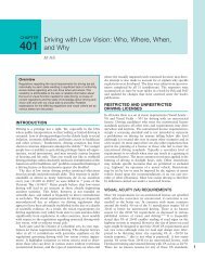
eye due to pupil coupling 40 . For <strong>the</strong> same example, assuming an eye pupil of 3mm, <strong>the</strong>maximum light efficiency is 90% (Fig. 16a) but is reduced to 80% with a square 8×8mmentrance pupil (Fig. 16c). With an eye pupil of 4mm, <strong>the</strong> light efficiency with <strong>the</strong> rectangleentrance pupil is reduced to 72% (Fig. 16b), but with <strong>the</strong> square pupil it will fall fur<strong>the</strong>r to 58%(Fig. 16d). Thus extending <strong>the</strong> horizontal dimension of <strong>the</strong> objective (which is possible) wouldimprove <strong>the</strong> light collection of <strong>the</strong> telescope when <strong>the</strong> pupil is enlarged (e.g., in dim lightconditions), compared with a square objective.Ø 3mm90%Ø 4mm72%abØ 3mm80%Ø 4mm58%cdFigure 16: improvements in light efficiency of <strong>the</strong> effective pupil of <strong>the</strong> eye-telescopesystem resulting from extending <strong>the</strong> exit pupil horizontally. Dashed squares andrectangles represent <strong>the</strong> exit pupil sizes <strong>for</strong> with 2 different eye pupil diameters (3 and4 mm, respectively) using both a square and horizontally extended entrance pupils.The light gain (or actual loss) is equal to <strong>the</strong> percentage area of <strong>the</strong> eye pupil coveredby <strong>the</strong> exit pupil, as shown in <strong>the</strong> diagrams. The benefit of a rectangular objective interms of light efficiency is shown to increase with increased eye pupil diameter.The overlap between <strong>the</strong> exit pupil and <strong>the</strong> eye’s pupil may also be reduced by scanningeye movements that take <strong>the</strong> pupil away from <strong>the</strong> center of <strong>the</strong> exit pupil. Since most eyemovements, especially with a wider horizontal FOV, will be in a lateral direction, <strong>the</strong> wider26
horizontal extent of <strong>the</strong> exit pupil will protect <strong>the</strong> light efficiency during such eye scanning.Thus a wider objective is desirable, even if <strong>the</strong> wider FOV is not necessary.We computed <strong>the</strong> effects of <strong>the</strong> carrier lens thickness on <strong>the</strong> maximal possible lightefficiency due to <strong>the</strong> exit pupil coupling. Fig. 17 shows <strong>the</strong> results <strong>for</strong> an eye centered on <strong>the</strong> exitpupil in a telescope of magnification 2.8×, as a function of eye pupil diameters, <strong>for</strong> two levels ofcarrier lens thickness (5 and 8mm respectively), and <strong>for</strong> different <strong>for</strong>mat factors representing <strong>the</strong>ratio of vertical to horizontal dimensions of <strong>the</strong> entrance pupil. Older people would present smallpupil diameters (about 3mm in diameter), while larger pupils would be expected <strong>for</strong> youngwearers under dim light conditions. As can be seen expanding <strong>the</strong> horizontal by a factor of 2substantially increases <strong>the</strong> maximum light efficiency <strong>for</strong> both levels of lens thickness. Expanding<strong>the</strong> entrance pupil fur<strong>the</strong>r horizontally results in minimal additional benefit (expanding <strong>the</strong> 8mmvertical entrance pupil to 8:24 results in no additional benefit over <strong>the</strong> 8:16 case (not shown)).Maximum Light Efficiency100%80%60%40%20%0%Format (mm)5:55:105:208:88:16Magnification 2.8×1 2 3 4 5 6 7Eye Pupil Diameter (mm)Figure 17: The influence of <strong>the</strong> carrier lens thickness, entrance pupil <strong>for</strong>mat factor, andeye’s pupil diameter on <strong>the</strong> light loss due to exit pupil coupling in a Keplerian telescopeof magnification 2.8×. For <strong>the</strong> 5mm lens thickness expanding <strong>the</strong> entrance pupilhorizontally to 10 mm substantially improves light efficiency <strong>for</strong> all pupil diameters.Fur<strong>the</strong>r expansion results in modest effect and only <strong>for</strong> large eye pupils. For <strong>the</strong> 8mm27
lens doubling <strong>the</strong> horizontal dimension is beneficial <strong>for</strong> all sub optimal pupil sizes butfur<strong>the</strong>r increase of horizontal dimension is of little value (not shown)4.3. Refractive CorrectionAs eyewear, <strong>the</strong> in-<strong>the</strong>-lens telescope must provide refractive correction <strong>for</strong> <strong>the</strong> wearerboth through <strong>the</strong> telescope and through <strong>the</strong> carrier lens. All our diagrams have illustrated <strong>the</strong>carrier lens as a flat lens on both sides and thus could be used only by individuals without anyrefractive error (emmetropes). A refractive correcting lens could be laminated to <strong>the</strong> backsurface of <strong>the</strong> lens or be ground into that surface. Such a correction will apply equally to <strong>the</strong>telescope and <strong>the</strong> carrier. A standard ophthalmic lens blank is usually provided as a meniscuslens with a front convex surface (base curve). The positive front base curve is needed <strong>for</strong> bettercosmetics and <strong>for</strong> improved optical per<strong>for</strong>mance 41 . The refractive correction is typically appliedusing widely available equipment to grind <strong>the</strong> back surface of <strong>the</strong> semi-finished lens blank. Thesame approach can be easily applied to <strong>the</strong> in-<strong>the</strong>-lens telescope. The lens blank <strong>for</strong> thistelescope may be developed with a fairly flat base curve. The telescope optical tube length needsto be slightly modified from <strong>the</strong> afocal configuration to result in a vergence at <strong>the</strong> second beamsplitter which is identical to that created by <strong>the</strong> base curve at <strong>the</strong> back surface. With such ablank, <strong>the</strong> back surface may be ground to <strong>the</strong> wearer’s prescription on <strong>the</strong> back surface usingstandard ophthalmic lab techniques and equipment. The correction applied to <strong>the</strong> carrier lenswill result in an appropriate correction <strong>for</strong> <strong>the</strong> telescope as well. This would make such a lenseasily dispensable in every ophthalmic shop. Tilts generated in <strong>the</strong> objective and <strong>the</strong> ocular dueto <strong>the</strong> prismatic effect of <strong>the</strong> carrier lens (Percival’s Rule) can be compensated by centering <strong>the</strong>curved surfaces on each beam splitter, if needed. Alternately, <strong>the</strong> prismatic effect may be used tosupport vision multiplexing.28
A side effect of using a curved carrier lens is that <strong>the</strong> magnification is slightly reducedcompared with <strong>the</strong> plano-parallel carrier lens equivalent, using <strong>the</strong> same curved mirrors. Thereason <strong>for</strong> such an effect can be easily described as an increase of <strong>the</strong> objective lens power and areduction of <strong>the</strong> ocular power due to <strong>the</strong> curved carrier surfaces. Thus, <strong>the</strong> magnification as <strong>the</strong>ratio of both refractive powers is reduced. To quantify <strong>the</strong> effect, we simulated <strong>the</strong> same modeldescribed in Fig. 15 embedded in three plano carrier lenses with base curve surfaces of 0, +1, and+3 diopters, resulting in angular magnifications of 3.3×, 3.2×, and 3.0×, respectively.5. DiscussionWe have described a novel design <strong>for</strong> bioptic telescopes. We have proposed and tested afamily of possible designs <strong>for</strong> Galilean and Keplerian bioptic telescopes using ei<strong>the</strong>r laminatedlenses, embedded curved mirrors, or polarizing converging beam splitters. We have analyzed<strong>the</strong>se designs through computer simulations and prototyped <strong>the</strong> designs to demonstrate <strong>the</strong>feasibility of such devices. These analyses provide insight into constraints on magnification,image quality, FOV, distortion, and <strong>the</strong>ir utility in vision multiplexing.Bioptic telescopes are <strong>the</strong> most efficient visual aid available <strong>for</strong> distance vision, yet <strong>the</strong>yare commonly rejected by people with low vision due to <strong>the</strong>ir appearance. Our approachaddresses this limitation while maintaining visual per<strong>for</strong>mance similar to or better than currentbioptic telescopes. Although <strong>the</strong> in-<strong>the</strong>-lens telescope is not cosmetically invisible, itscompactness and internalized components attract less attention than current designs. Figure 18shows a conceptual simulation of <strong>the</strong> appearance of <strong>the</strong> in-<strong>the</strong>-lens Keplerian telescope.29
Figure 18: Simulation of <strong>the</strong> expectedappearance of <strong>the</strong> in-<strong>the</strong>-lens telescope.The proposed in-<strong>the</strong>-lens telescope can be used to simultaneously view <strong>the</strong> magnifiedimage and <strong>the</strong> unmagnified image of <strong>the</strong> same area. This vision multiplexing feature improveswearer orientation and navigation. The wearer can easily locate an object or determine <strong>the</strong>relative position of <strong>the</strong> object. The spectacle lens can include <strong>the</strong> wearer’s correctingprescription. We believe that <strong>the</strong>se features will make this device very desirable and that <strong>the</strong>ability to incorporate <strong>the</strong> wearer’s prescription using standard ophthalmic procedures will control<strong>the</strong> cost of <strong>the</strong> device and will support its wide distribution.ACNOWLEDGMENTSSupported in part by NIH grants EY 12890 and EY05957. F. Vargas-Martín received a travelgrant from Fundación Séneca, (Murcia, Spain). We thank Morey Waltuck <strong>for</strong> help with <strong>the</strong>construction of <strong>the</strong> Keplerian design with laminated lenses and, Gang Luo <strong>for</strong> help with <strong>the</strong>construction of <strong>the</strong> off-axis parabolic mirrors prototype.REFERENCES1. G.R. Watson, J. Maino and W. De L'aune, "Comparison of low-vision reading withspectacle-mounted magnifiers," Journal of Rehabilitation Research and Development,42/4, 459-470 (2005).2. E. Peli and W.P. Siegmund, "Fiber optic reading magnifier <strong>for</strong> <strong>the</strong> visually impaired,"Journal of <strong>the</strong> Optical Society of America A, 12/10, 2274-2285 (1995).30
3. R. Lund and G.R. Watson, The CCTV Book: Habilitation and Rehabiliation with ClosedCircuit Television Systems. The CCTV Book, LUVReading Series (Syns<strong>for</strong>um ans.,Froland, Norway, 1997)4. C. Dickinson, <strong>Low</strong> <strong>Vision</strong>: Principles and Practice (Butterworth, Ox<strong>for</strong>d, 1998)5. H.A. Greene, R. Beadles and J. Pekar, "Challenges in applying auto-focus technology tolow vision telescopes," Optometry & <strong>Vision</strong> Science, 69/1, 25-31 (1992).6. E. Peli, "<strong>Vision</strong> multiplexing: an engineering approach to vision rehabilitation devicedevelopment," Optometry and <strong>Vision</strong> Science, 78/5, 304-315 (2001).7. E. Peli and D. Peli, Driving With Confidence: A Practical Guide to Driving With <strong>Low</strong><strong>Vision</strong> (World Scientific, Singapore, 2002)8. A.R. Bowers, D.H. Apfelbaum and E. Peli, "Bioptic telescopes meet <strong>the</strong> needs of driverswith moderate visual acuity loss," <strong>In</strong>vestigative Ophthalmology & <strong>Vision</strong> Science, 46/1,66-74 (2005).9. A. Simon, "Fernbrille," Germany patent 302387 (1917).10. B.Q. Jones, "Goggles," USA patent 1,610,553 (October 31, 1924, 1924).11. J. Bartschat, "Brillenartige Haltevorrichtung fur Doppelfernrohne," Germany patent 863423 (1953).12. W. Feinbloom, "Driving with bioptic telescopic spectacles," American Journal ofOptometry & Physiological Optics, 54(1), 35-42 (1977).13. T. Harkins and J.H. Maino, "The BITA telescope: a first impression," Journal of <strong>the</strong>American Optometric Association, 62/1, 28-31 (1991).14. A. Nguyen, A.-T. Nguyen, R.P. Hemenger and D.R. Williams, "Resolution, field of view,and retinal illuminance of miniaturized bioptic telescopes and <strong>the</strong>ir clinical significance,"Journal of <strong>Vision</strong> Rehabilitation, 7, 5-9 (1993).15. J.P. Szlyk, W. Seiple, D.J. Laderman, R. Kelsch, J. Stelmack and T. McMahon,"Measuring <strong>the</strong> effectiveness of bioptic telescopes <strong>for</strong> persons with central vision loss,"Journal of Rehabilitation Research and Development, 37/1, 101-108 (2000).16. H.A. Greene and J. Pekar, "Bioptic telescope utilization survey," Journal of <strong>Vision</strong>Rehabilitation, 1/3, 39-48 (1987).17. R.T. Jose, L.A. Spitzberg and C.L. Kue<strong>the</strong>r, "A behind <strong>the</strong> lens reversed (BTLR)telescope," Journal of <strong>Vision</strong> Rehabilitation, 3, 37-46 (1989).18. L. Spitzberg, R.T. Jose and C.L. Kue<strong>the</strong>r, "Behind <strong>the</strong> lens telescope: A new concept inbioptics," Optometry and <strong>Vision</strong> Science, 66, 616-620 (1989).19. H.A. Greene, J. Pekar, R. Brilliant, P.B. Freeman, H.T. Lewis, R. Siwoff, C. Paton, D.J.Madden and R. Westlund, "The Ocutech <strong>Vision</strong> Enhancing System (VES): Utilizationand Preference Study," Journal of <strong>the</strong> American Optometric Association, 62/1, 19-27(1991).20. D.R. Williams, "The bi-level telemicroscopic apparatus--(BITA)," Problems inOptometry, 3/3, 495-503 (1991).21. W.F. Hoeft, "The microspiral galilean telescope," Problems in Optometry, 3, 490-494(1991).22. W.M. Ludlam, "Clinical experience with <strong>the</strong> contact lens telescope," Am. J. Optom.,37/7, 363-372 (1960).23. T.R. Willis and V. Portney, "Preliminary evaluation of <strong>the</strong> Koziol-Peyman teledioptricsystem <strong>for</strong> age-related macular degeneration," European Journal of Implant andRefractive Surgery, 1, 271-276 (1989).24. I.L. Bailey, "Critical view of an ocular telephoto system," The CLAO Journal, 13/4, 217-221 (1987).25. E. Peli, "The optical functional advantages of an intraocular low-vision telescope,"Optometry and <strong>Vision</strong> Science, 79/4, 225-233. (2002).31
26. D. Rushton and N. Cox, "A new optical treatment <strong>for</strong> oscillopsia," Journal of Neurology,Neurosurgery & Psychiatry, 50/4, 411-415 (1987).27. L. Moore, "The contact lens <strong>for</strong> subnormal visual acuity," British Journal ofPhysiological Optics, 21, 203-204 (1964).28. J.E. Koziol, G.A. Peyman, R. Cionni, J.S. Chou, V. Portney, R. Sun and D. Trentacost,"Evaluation and implantation of a teledioptric lens system <strong>for</strong> cataract and age-relatedmacular degeneration," Ophthalmic Surgery, 25/10, 675-684 (1994).29. E. Peli, "Double bifocal telescopic IOL-spectacle device <strong>for</strong> low vision use," UnitedStates patent application 60/ 310,664 (2001).30. E. Peli, I. Lipshitz and G. Dotan, "Implantable miniaturized telescope (IMT) <strong>for</strong> lowvision." in C. Stuen, et al., Eds. <strong>Vision</strong> Rehabilitation: Assessment, <strong>In</strong>tervention andOutcomes, 200-203 (Swets & Zeitlinger, Lisse, 2000)31. H.L. Hudson, S.S. Lane, J.S. Heier, R.D. Stulting, L. Singerman, P.R. Lichter, P.Sternberg and D.F. Chang, "Implantable miniature telescope <strong>for</strong> <strong>the</strong> treatment of visualacuity loss resulting from end-stage age-related macular degeneration: 1-year results,"Ophthalmology, 113/11, 1987-2001 (2006).32. G. Fonda, "Approach magnification is safer than bioptic telescopic spectacles <strong>for</strong>operating a motor vehicle," Transactions Pennsylvania Academy of Ophthalmology andOtolaryngology, 35/2, 137-40 (1982).33. G. Fonda, "Bioptic telescopic spectacle is a hazard <strong>for</strong> operating a motor vehicle," ArchOphthalmol, 101, 1907-1908 (1983).34. O. Lippmann, A.L. Corn and M.C. Lewis, "Bioptic telescopic spectacles and drivingper<strong>for</strong>mance: A study in Texas," Journal of Visual Impairment & Blindness, 82/5, 182-187 (1988).35. BITA, Bita Reference Manual (Edwards Optical Corporation, 1989)36. E. Peli and F. Vargas-Martin, "Bioptic telescope system embedded into a spectacle lens,"United States patent 6,775,060 (August 10, 2004, 2004).37. J. Schwiegerling, Field guide to visual and ophthalmic optics. 1st ed. SPIE Field Guides(SPIE-The <strong>In</strong>ternational Society <strong>for</strong> Optical Engineering (SPIE Press), Bellingham, WA,2004)38. W.B. Wolfe, "Nondispersive Prisms", in v.S.E. Bass M, Williams DR, Wolfe WI, eds,Ed. The Handbook of Optics, 4.1-29 (McGraw Hill, New York, 1994)39. M.B. Spitzer, P.M. Zavracky, J. Craw<strong>for</strong>d, P. Aquilino and G. Hunter, "Eyewearplat<strong>for</strong>ms <strong>for</strong> miniature displays," in Digest of Technical Papers SID 01, (Society <strong>for</strong><strong>In</strong><strong>for</strong>mation Display, 2001), pp. 258-261.40. G. Smith and D.A. Atchison, "<strong>In</strong>strument exit pupil size (Part VI., Section 36.4.2)", inThe Eye and Visual Optics <strong>In</strong>struments, 706-708 (Cambridge University Press,Cambridge United Kingdon, 1997)41. D.A. Atchison, "<strong>Spectacle</strong> lens design: a review," Applied Optics, 31/19, 3579-3585(1992).32