In-the-Spectacle-Lens Telescopic Device for Low Vision
In-the-Spectacle-Lens Telescopic Device for Low Vision
In-the-Spectacle-Lens Telescopic Device for Low Vision

Create successful ePaper yourself
Turn your PDF publications into a flip-book with our unique Google optimized e-Paper software.
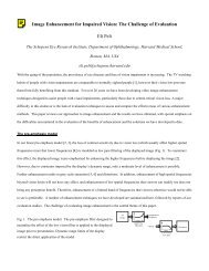
a 5 mm thick carrier lens). Mirrors were embedded in a flat carrier lens of BK7 glass (Fig. 14a).This design resulted in a convenient eye relief of 15mm from <strong>the</strong> back surface of <strong>the</strong> carrier lens.Image quality, in terms of <strong>the</strong> PSF or modulation transfer function (MTF), wassatisfactory in <strong>the</strong> central field, but degraded rapidly with increasing eccentricity (Fig. 14b). Dueto <strong>the</strong> rapid degradation of <strong>the</strong> image in <strong>the</strong> vertical direction, increasing <strong>the</strong> vertical dimensionof <strong>the</strong> mirrors provided no effective increase in vertical field. The main effect illustrated by thisanalysis was <strong>the</strong> anisotropic distortion due to <strong>the</strong> differences in curvature that mirrors present totilted rays (Fig. 14b). The distortion was confirmed in a prototype of this design, which enabledus to experience <strong>the</strong> disturbing visual effect of <strong>the</strong> distortion (as described in section 2.5).PRabFigure 14: a) 3D layout and ray tracing of <strong>the</strong> off-axis parabolic mirror design showingeye pupil (P) and retina (R). . Rectangles represent effective areas <strong>for</strong> <strong>the</strong> first andsecond surfaces of <strong>the</strong> carrier lens. b) Image from two square 5×5 grid objects,subtending 5º and 15º respectively. Notice <strong>the</strong> similarity of <strong>the</strong> distortion to that shownin Fig. 9.3.2. Keplerian design with beam splittersThis is <strong>the</strong> design described generically in section 2.6. Using a bi-planar carrier lens of8mm thickness, <strong>the</strong> following design achieved a 1:2 <strong>for</strong>mat in <strong>the</strong> image field with an entrancepupil of 16mm horizontally and 8mm vertically. As described be<strong>for</strong>e, two polarizing beamsplitters, in combination with thin quarter wave phase plates, allowed <strong>the</strong> use of on-axis spherical23