Logical control functions - TechTeach
Logical control functions - TechTeach
Logical control functions - TechTeach
- No tags were found...

You also want an ePaper? Increase the reach of your titles
YUMPU automatically turns print PDFs into web optimized ePapers that Google loves.
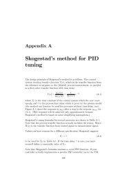
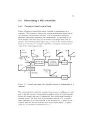
Chapter 6<strong>Logical</strong> <strong>control</strong>6.1 IntroductionFigure 6.1 shows a <strong>control</strong>ler with input signals (or variables) and outputsignals (variables). The <strong>control</strong>ler may be a PLC, or some similar <strong>control</strong>equipment, cf. Section 3.InputsOutputsy 1x 1x 3y 3x 2Controllery 2Figure 6.1: A <strong>control</strong>ler with input signals and output signalsThe values of the <strong>control</strong>ler outputs may be generated by <strong>functions</strong> of<strong>control</strong>ler inputs or as a result of e.g. some calculations or comparisonsbetween variables. Here are few examples:• A motor is started if a start button is pressed.• A valve is closed if the level of the liquid in a tank is larger than aspecific level.In logical <strong>control</strong> the output variables have one of two possible binaryvalues. And some of the inputs to the <strong>control</strong>ler may also have binary19
20 Finn Haugen, <strong>TechTeach</strong>: Computer-based measurement and <strong>control</strong>values. These binary values are described in the following section.6.2 <strong>Logical</strong> variablesA logical variable can have one of two possible binary values. These valuesmay be given various names or symbols, as shown in Table 6.1.TRUE FALSEON OFFHIGH LOW1 0Table 6.1: Various names (symbols) on the two possible binary valuesThe physical representation of these values depends on the equipment ormedia. Here are some examples:• TTL (transistor-transistor-logic): The binary value FALSE isrepresented by a voltage in the range [0V, 0.8V]. Value TRUE is anyvoltage above 2V.• Aswitchorarelayoratransistor: Value FALSE (or OFF)means the element is open, i.e. does not conduct current. ValueTRUE (ON) means the element is closed, i.e. it is conductingcurrent.• Avalve: Value TRUE means the valve is open. Value FALSEmeans the valve is closed.6.3 <strong>Logical</strong> <strong>functions</strong>6.3.1 IntroductionIn the following sections three basic logical <strong>functions</strong> operating on logicalvariables are defined. These <strong>functions</strong> are• AND• OR
Finn Haugen, <strong>TechTeach</strong>: Computer-based measurement and <strong>control</strong> 21• NOTThey are available in the programming tool of any PLC, in Matlab,LabVIEW, C++, Delphi, Visual Basic, etc. By combining these basic<strong>functions</strong> you can construct more complicated <strong>functions</strong>. In the followingsections it is shown how the <strong>functions</strong> are defined and documented using atruth table, and it will be shown how the <strong>functions</strong> are represented in• Boolean expression• Function block diagram language (FB) defined in the IEC 61131-3standard of PLC programming. The FB language is a graphicalprogramming language. This means that you develop the program byconnecting <strong>functions</strong> together in a diagram.• Ladder diagram language (LD) defined in the IEC 61131-3 standard.The LD language is also a graphical programming language.• Structured text language (ST) defined in the IEC 61131-3 standard.The ST language is a textual language similar to Pascal or Delphi.In addition to the basic boolean <strong>functions</strong> as AND, OR, NOT etc.,you can use expressions as If..Then..Else, Case , While loops, Forloops, etc.• LabVIEW6.3.2 AND functionPseudo codeThe AND function may be expressed as follows (in pseudo code) where x 1and x 2 are inputs and y is output:y = x 1 AND x 2 (6.1)“AND” can also be regarded as an operator.Boolean expressionThe AND function is expressed as follows in a boolean expression:y = x 1 ∗ x 2 = x 1 x 2 (6.2)Note that in this context the asterix operator * does not mean arithmeticalmultiplication. As indicated, the asterix can be omitted.
22 Finn Haugen, <strong>TechTeach</strong>: Computer-based measurement and <strong>control</strong>Truth tableTable 6.2 shows the truth table of the AND function. A truth table definesthe output value for all possible combinations of the input values.x 1 x 2 y0 0 00 1 01 0 01 1 1Table 6.2: Truth table of the AND functionFunction blockFigure 6.2 shows a function block representing the AND function. Thissymbol is according to the IEC 61131-3 standard of PLC programming.(There is also a US symbols standard, but US symbols are not shown here.)Inputsx 1x 2&OutputyFigure 6.2: Function block symbol of the AND functionLadder diagramFigure 6.3 shows the AND function in a ladder diagram. Ladder diagramsare one of the languages defined in the IEC 61131-3 standard. Ladderdiagrams depicts a hypothetical electrical circuit diagram. A contact canconduct or not conduct current originating from the power rail. For theAND operation, current is flowing to the coil y only if both contacts x 1and x 2 are conducting. In other words, y is ON or TRUE only if both x 1and x 2 are ON or TRUE. “Contact” is used as a synonym for input, while“coil” is a synonym for output.
Finn Haugen, <strong>TechTeach</strong>: Computer-based measurement and <strong>control</strong> 23InputsOutputx 1 x 2 yPower railContactsCoilFigure 6.3: The AND function in a ladder diagramStructured textIn the Structured text language the AND function can be used as follows:You can also write y := x 1 & x 2 ;.y := x 1 AND x 2 ; (6.3)LabVIEWFigure 6.4 shows the AND function in LabVIEW.Figure 6.4: The AND function in LabVIEW6.3.3 OR functionPseudo codey = x 1 OR x 2 (6.4)
24 Finn Haugen, <strong>TechTeach</strong>: Computer-based measurement and <strong>control</strong>Boolean expressiony = x 1 + x 2 (6.5)Note that the asterix operator + does not mean arithmetical addition, butlogical OR.Truth tableSee Table 6.3.x 1 x 2 y0 0 00 1 11 0 11 1 1Table 6.3: Truth table of the OR functionFunction blockSee Figure 6.5.Figure 6.5: Function block symbol of the OR functionLadder diagramSee Figure 6.6.Structured textIn the Structured text language the OR function can be expressed asy := x 1 OR x 2 ; (6.6)
Finn Haugen, <strong>TechTeach</strong>: Computer-based measurement and <strong>control</strong> 25Inputsx 1Outputyx 2Figure 6.6: The OR function in a ladder diagramYou can also write y = x 1 + x 2 ;.LabVIEWSee Figure 6.7.Figure 6.7: The OR function in LabVIEW6.3.4 NOT functionThe NOT function has only one input. It is also denoted the logicalinverter function.Pseudo codey = NOT x (6.7)
26 Finn Haugen, <strong>TechTeach</strong>: Computer-based measurement and <strong>control</strong>Boolean expressiony = x (6.8)Truth tableSee Table 6.4.x y0 11 0Table 6.4: Truth table of the NOT functionFunction blockSee Figure 6.8.Inputx&OutputyFigure 6.8: Function block symbol of the NOT functionLadder diagramFigure 6.9 shows how the NOT function is realized using a normally closedcontact. “Normally closed” means that the contact is closed, i.e. it is notconducting current if you think if it as a real electrical contact, if it is in a“passive” state, i.e. if the variable has value OFF (or FALSE or 0). Thecontact used in Figure 6.3 is a normally open contact.Structured textIn the Structured text language the NOT function is used as follows:y = NOT x; (6.9)
Finn Haugen, <strong>TechTeach</strong>: Computer-based measurement and <strong>control</strong> 27InputxOutputyFigure 6.9: The NOT function in a ladder diagramLabVIEWSee Figure 6.10.Figure 6.10: The NOT function in LabVIEW6.4 Compound logical <strong>functions</strong>Basic logical <strong>functions</strong> can be combined to realize compound logical<strong>functions</strong>. Assume as an example the following function:y =(x 1 AND x 2 ) OR x 3 (6.10)This function can be realized in a function block diagram as shown inFigure 6.11. And Figure 6.12 shows how the function can be realized in ax 1x 2&x 3=1yFigure 6.11: Function block diagram realizing the compund function y =(x 1AND x 2 ) OR x 3ladder diagram.
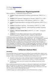
28 Finn Haugen, <strong>TechTeach</strong>: Computer-based measurement and <strong>control</strong>Figure 6.12: Ladder diagram realizing the compund function y =(x 1 AND x 2 )OR x 36.5 Various <strong>functions</strong> typically supported byPLCsPLCs may have hundreds of <strong>functions</strong> in addition to the basic AND, ORand NOT <strong>functions</strong> described above. In the following sections a few of themost important additional <strong>functions</strong> are described.6.5.1 TimersA timer function is similar to a clock which is started (triggered) by astarting signal changing value from OFF to ON. When a preset time haselapsed, the timer output is set to ON. As an example, a timer can be usedto implement a time-delayed start of a motor. Another example is to<strong>control</strong> the ON-time of en heater.PLCs have a number of different timers in their <strong>functions</strong> library. Figure6.13 shows an example of a timer. (The example can be found in a user’smanual of the GX IEC Developer programming tool of Mitsubishi PLCs.)x0InputsTimer1ENQOutputsM0T#1m10s25msPTETD0Figure 6.13: An example of a timer functionThe timer parameters are as follows.• Input EN (enable) [boolean] starts or triggers the timer.
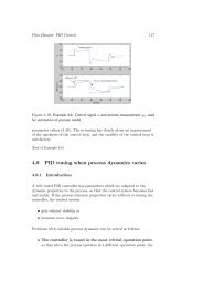
Finn Haugen, <strong>TechTeach</strong>: Computer-based measurement and <strong>control</strong> 29• Input PT (preset time) [time] is the (elapsed) time or time delaybefore the timer output Q is set to ON. The time format is a specialdata format used to represent time. In Figure the PT value is 1minute 10 second 25 milliseconds.• Output Q (output 1 ) [boolean] is the timer output. It gets value ONwhen the elapsed time is larger than the preset time.• Output ET (elapsed time) [time] is the continuously running time.Figure 6.14 shows a timing diagram which shows the behaviour of thetimer along a time axis. The timer operates as follows:EN:OFF (0)ON (1)1m10s25msET:0sON (1)Q:OFF (0)Time:t 0 t 1 t 2 t 3 t 4Elapsed time isPT=1m10s25msElapsed time isless than PTFigure 6.14: Typical timing diagram of a timer• The timer starts when the input x0 at the EN input goes from OFFto ON. As the timer starts, the ET output increases continuouslyfrom the initial value of 0 seconds. In this example, the ET timevalue is stored in the data register D0 which is a general register or1 Q means output. The ideal symbol O for output is not used since it is too easilymisinterpreted as zero.
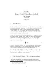
30 Finn Haugen, <strong>TechTeach</strong>: Computer-based measurement and <strong>control</strong>memory cell where a value can be stored for use in subsequentprogramming expressions.• When the ET time has become larger than the PT (preset time)value the boolean output Q is set to ON. In this example, the valueof Q is stored in memory cell M0 which is a general memory cellwhere a boolean value can be stored for use in subsequentprogramming expressions.• If EN goes from ON to OFF, ET is reset to zero.6.5.2 CountersA counter is a function which counts the number of times a boolean inputvariable has changed value either from OFF to ON, or from ON to OFF,or both. As an example, a counter can be used to count the number ofbottles passing a photo diode.In a given PLC there are various counters available in the library of<strong>functions</strong>. Figure 6.15 shows an example of a counter.Inputsx0x15Counter1CI QRESETPV CVOutputsM0D0Figure 6.15: A example of a counterHere is a description of the parameters and the operation of the counter:• Input CI (counter input) [boolean] is the signal of which the changesfrom OFF to ON is to be counted. (The change from OFF to ON isdenoted the positive edge of the signal.)• Input RESET [boolean]: Value ON resets the counter value CV tozero.• Input PV (preset value) [integer] is the preset “target” value of thecounter. In 6.15 PV is 5, as an example.
Finn Haugen, <strong>TechTeach</strong>: Computer-based measurement and <strong>control</strong> 31• Output Q (output) [boolean] is the counter output. It gets value ONwhen the counted number, CV, is equal to or larger than the presetcounter value, PV. Otherwise it has value OFF.• Output CV (counter value) [integer] is the number of times thecounter input, CI, has changed from OFF to ON.Figure 6.16 illustrates how the counter works.CI:OFF (0)ON (1)ON (1)RESET:OFF (0)CV:6543210PV=5ON (1)Q:OFF (0)Figure 6.16: The operation of a counter6.5.3 LatchesNot described yet.