SigmaFire Installation Manual, rev. F - Clayton Industries
SigmaFire Installation Manual, rev. F - Clayton Industries
SigmaFire Installation Manual, rev. F - Clayton Industries

You also want an ePaper? Increase the reach of your titles
YUMPU automatically turns print PDFs into web optimized ePapers that Google loves.
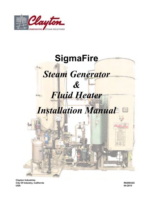
Cover<strong>SigmaFire</strong>Steam Generator&Fluid Heater<strong>Installation</strong> <strong>Manual</strong><strong>Clayton</strong> <strong>Industries</strong>City Of Industry, CaliforniaR020932GUSA 04-2015
WARRANTY<strong>Clayton</strong> warrants its equipment to be free from defects in material and/or workmanship for a period of 1 year from date oforiginal installation, or 15 months from date of shipment from the factory, whichever is shorter. Upon expiration of suchwarranty period, all liability of <strong>Clayton</strong> shall immediately cease. During the warranty period if the <strong>Clayton</strong> product is subjectedto improper installation, misuse, negligence, alteration, accident, improper repair, or operated contrary to <strong>Clayton</strong>’s printedinstructions; all liability of <strong>Clayton</strong> shall immediately cease. THE FOREGOING WARRANTY IS EXCLUSIVE AND IN LIEU OFALL OTHER WARRANTIES, EXCEPT TITLE AND DESCRIPTION, WHETHER WRITTEN, ORAL OR IMPLIED, ANDCLAYTON MAKES NO WARRANTY OF MERCHANTABILITY OR FITNESS FOR PURPOSE. No representative of <strong>Clayton</strong>has any authority to waive, alter, vary, or add to the terms hereof without prior approval in writing executed by two officers of<strong>Clayton</strong> <strong>Industries</strong>.If within the period of such warranty the purchaser promptly notifies <strong>Clayton</strong>’s Service Department (Attention: WarrantyRepairs, Cincinnati, OH) in writing of any claimed defect; and if requested by <strong>Clayton</strong>, promptly returns the part(s) claimeddefective to <strong>Clayton</strong>’s manufacturing facility with all transportation charges prepaid to <strong>Clayton</strong>, <strong>Clayton</strong> will consider saidpart(s) covered under this warranty. All parts returned must be shipped to <strong>Clayton</strong>’s Cincinnati, OH facility (Attention: WarrantyRepairs, Cincinnati, OH) except coils which must be shipped to <strong>Clayton</strong>’s City of Industry, CA facility (Attention: WarrantyRepairs, City of Industry, CA). Once <strong>rev</strong>iewed by <strong>Clayton</strong>, if it appears to <strong>Clayton</strong> that such part(s) is defective in material and/or workmanship, <strong>Clayton</strong> will at its sole discretion & choice repair such defective part(s), or replace same with like or similarpart(s), or provide a credit for the part(s). The purchaser shall be responsible for all transportation and labor charges relatingto installation of any replacement part or removal of a defective part.It is expressly understood that the repair or replacement of such defective part(s) by <strong>Clayton</strong> shall constitute the soleremedy of purchaser and sole liability of <strong>Clayton</strong> whether on warranty, contract, or negligence; and that <strong>Clayton</strong> shall not beliable for any other expense, injury, loss, or damage whether direct, incidental, or consequential.With respect to any non-<strong>Clayton</strong> part(s) supplied hereunder; other than the duration of the warranty, the OEMmanufacturer’s warranty shall apply and be exclusive.Goods sold or delivered may, at <strong>Clayton</strong>’s discretion, consist in part of reconditioned or reassembled parts which havebeen inspected and checked by <strong>Clayton</strong> and which are fully covered by such warranty as if new. In performing its warranty asobligations hereunder, <strong>Clayton</strong> may in its discretion repair or replace any part with such a reconditioned or reassembled part.<strong>Clayton</strong> Service BranchesU.S. & CANADA FACTORY DIRECT SERVICE BRANCHESATLANTA 125-A Howell Road, Tyrone, GA 30290 (770) 632-9790CANADA 13 Edvac Drive, Unit 18, Brampton, ON L6S5W6 (905) 791-3322CHICAGO 37 Sherwood Terrace Unit 110, Lake Bluff, IL 60044 (847) 295-1007CINCINNATI 3051 Exon Avenue, Cincinnati, OH 45241 (513) 563-1300CLEVELAND 9241 Ravenna Road Suite C2, Twinsburg, OH 44087 (330) 425-8006DALLAS 719 Ashford Lane, Wylie, TX 75098 (972) 224-5011DETROIT 37648 Hills Tech Drive, Farmington Hills, MI 48331 (248) 553-0044KANSAS CITY 1600 Genessee Suite 524, Kansas City, MO 64102 (816) 221-2411LOS ANGELES 17477 Hurley Street, City of Industry, CA 91744 (626) 435-1200NEW ENGLAND 387 Page Street, Unit 11A, Stoughton, MA 02072 (781) 341-2801NEW JERSEY 10 South River Road Suite 6, Cranbury, NJ 08512 (609) 409-9400NORTHERN CALIFORNIA P.O. Box 1956, Bethel Island, CA 94511 (510) 782-0283
Title Page<strong>SigmaFire</strong>Steam GeneratorandFluid Heater<strong>Installation</strong> <strong>Manual</strong>
CLAYTON INDUSTRIES17477 Hurley StreetCity of Industry, CA 91744-5106USAPhone: +1 (626) 435-1200FAX: +1 (626) 435-0180Internet: www.claytonindustries.comEmail: sales@claytonindustries.com© Copyright 2009, 2011, 2013 <strong>Clayton</strong> <strong>Industries</strong>. All rights reserved.No part of this publication may be reproduced, stored in a retrieval system, or transmitted in any form or by any means(electronic, mechanical, photocopy, recording, or otherwise) without written permission from <strong>Clayton</strong> <strong>Industries</strong>.The descriptions and specifications shown were in effect at the time this publication was approved for printing. <strong>Clayton</strong><strong>Industries</strong>, whose policy is one of continuous improvement, reserves the right to discontinue models at any time, orchange specifications or design without notice and without incurring any obligation.FACTORY DIRECT SALES AND SERVICEUNITED STATES OFFICESATLANTA • CHICAGO • CINCINNATI • CLEVELAND • DALLAS • DETROITKANSAS CITY • LOS ANGELES • NEW ENGLAND • NEW JERSEYNORTHERN CALIFORNIALICENSEES, AFFILIATES, SALES and SERVICE DISTRIBUTORS WORLDWIDE
Table of ContentsSection 1 Introduction ................................................................................................................ 1-1Section 2 General Information .................................................................................................. 2-12.1 Location .............................................................................................................. 2-12.2 Positioning and Anchoring Equipment .............................................................. 2-22.2.1 General <strong>Installation</strong> Requirements ............................................................. 2-22.2.2 Equipment Anchoring ................................................................................ 2-32.2.3 Grouting ..................................................................................................... 2-32.2.4 <strong>Clayton</strong> PD Feedwater Pump Placement ................................................... 2-42.3 Combustion Air .................................................................................................. 2-42.4 Customer Connections - Steam Generator ......................................................... 2-42.5 Exhaust Stack <strong>Installation</strong> .................................................................................. 2-52.5.1 Installing Exhaust Stacks ........................................................................... 2-52.5.2 Installing Exhaust Stacks With External Condensing Economizer ......... 2-112.6 Piping ............................................................................................................... 2-132.6.1 General ..................................................................................................... 2-132.6.2 Systems .................................................................................................... 2-132.6.3 Atmospheric Test Valve ........................................................................... 2-152.6.4 Steam Header and Steam Sample Points ................................................. 2-152.7 Feedwater Treatment ........................................................................................ 2-152.7.1 Water Softeners ........................................................................................ 2-162.7.2 Make-up Water Line Sizing ..................................................................... 2-162.8 Feedwater Supply Requirements ...................................................................... 2-172.8.1 Multi-unit Systems ................................................................................... 2-172.8.2 Velocity Requirements and Calculation ................................................... 2-182.8.3 Acceleration Head (H a ) Requirements .................................................... 2-212.9 Flexible Feedwater Hose Connection And Connection Sizing ........................ 2-222.9.1 Supply Side Connections ......................................................................... 2-222.9.2 Discharge Side Connections .................................................................... 2-222.10 Pump Suction and Discharge Piping System Design ....................................... 2-222.10.1 General Layout Guidelines ...................................................................... 2-222.10.2 Pipe Sizing Guidelines ............................................................................. 2-232.11 Net Positive Suction Head (NPSH) .................................................................. 2-242.11.1 NPSHA .................................................................................................... 2-252.11.2 NPSHR ..................................................................................................... 2-25iii
2.11.3 Acceleration Head (H a ) ............................................................................ 2-262.12 General <strong>Installation</strong> Concerns .......................................................................... 2-282.12.1 Charge Pumps .......................................................................................... 2-282.12.2 Charge Pumps Are Not A Substitute ....................................................... 2-282.12.3 Multiple Pump Hookup ........................................................................... 2-282.12.4 Pumphead Cooling Water System (<strong>Clayton</strong> Feedwater Pumps) .............. 2-282.13 Electrical ........................................................................................................... 2-282.14 Electrical Grounding ........................................................................................ 2-29Section 3 <strong>Clayton</strong> Feedwater Systems ...................................................................................... 3-13.1 General ............................................................................................................... 3-13.2 Skid Packages ..................................................................................................... 3-13.3 Customer Connections ....................................................................................... 3-23.4 Open System ...................................................................................................... 3-33.5 Deaerator (DA) ................................................................................................... 3-53.6 Semi-closed Receiver (SCR) .............................................................................. 3-73.7 SCR Skids .......................................................................................................... 3-83.8 Head Tank .......................................................................................................... 3-8Section 4 Fuel System ................................................................................................................. 4-14.1 General ............................................................................................................... 4-14.2 Natural Gas ......................................................................................................... 4-14.3 Oil ....................................................................................................................... 4-24.3.1 General ....................................................................................................... 4-24.3.2 Light Oil ..................................................................................................... 4-2Section 5 Trap Separators ......................................................................................................... 5-15.1 General ............................................................................................................... 5-15.2 Operation ............................................................................................................ 5-15.3 <strong>Installation</strong> .......................................................................................................... 5-25.3.1 General ....................................................................................................... 5-25.3.2 Trap Separator Vent ................................................................................... 5-25.3.3 Feedwater Receiver Supply Lines ............................................................. 5-2Section 6 Technical Specifications ............................................................................................. 6-16.1 General ............................................................................................................... 6-16.2 Agency Approvals .............................................................................................. 6-16.3 Construction Materials ....................................................................................... 6-16.4 Flame Safeguard ................................................................................................. 6-16.5 Safety Controls ................................................................................................... 6-2iv
STEAM GENERATOR & FLUID HEATERINSTALLATION MANUAL(This page intentionally left blank.)Sect01_e.fm 1-2 04/22/2015
SECTION II - GENERALINFORMATION2.1 LOCATIONGive careful consideration to your <strong>Clayton</strong> equipment investment and the equipment warrantywhen selecting an installation location. The equipment should be located within close proximity to necessaryutilities, such as fuel, water, electricity, and ventilation. General consumption data for each model isprovided in Table 1 of Section VI. General equipment layout and dimensions are provided in Table 2 ofSection VI. For actual dimensions and consumption information, please refer to the data submitted witheach specific order.NOTE<strong>Clayton</strong>’s standard equipment is intended for indoor use only. <strong>Clayton</strong>’s equipmentmust be protected from weather at all times. The steam generator/fluid heater, andany associated water and chemical treatment equipment must be maintained at atemperature above 45° F (7° C) at all times.Maintain adequate clearance around your <strong>Clayton</strong> equipment for servicing needs. Maintain a minimumclearance of 60 inches (1.5 m) in front of the equipment, a minimum clearance of 36 inches (1 m) tothe left and right sides, and a minimum clearance of 18 inches (0.5 m) to the rear of the equipment. Ampleoverhead clearance, including clearance for lifting equipment, should be considered in case the coilrequires removing. Equipment layout and dimensions are provided in Table 2 of Section VI. Review thePlan <strong>Installation</strong> drawing supplied with the order for specific dimensions and clearance information.CAUTIONALL combustible materials must be kept a minimum of 48 inches (1.2 m) from thefront and 18 inches (0.5 m) from the top, rear, and sides of the equipment. A minimumclearance of 18 inches (0.5 m) must also be maintained around the flue pipe.Flooring shall be non-combustible. This equipment must not be installed in an areasusceptible to corrosive or combustible vapors.IMPORTANTKEEP CLAYTON EQUIPMENT CLEAR OF ALL OBSTRUCTIONS. DO NOTROUTE ANY NON-CLAYTON PIPING, ELECTRICAL CONDUIT, WIRING, ORAPPARATUS INTO, THROUGH, OR UNDER CLAYTON EQUIPMENT. ANYOBSTRUCTIONS CREATED BY SUCH NON-CLAYTON APPARATUS WILL VERYLIKELY INTERFERE WITH THE PROPER OPERATION AND SERVICING OF THE04/21/2015 2-1 Sect02_Genrl-SF_q.fm
Steam Generator & Fluid Heater<strong>Installation</strong> <strong>Manual</strong>EQUIPMENT. ALL SUCH INTERFERENCE IS THE SOLE RESPOSIBILITY OF THECUSTOMER. CLAYTON’S PLAN INSTALLATION DRAWINGS, INCLUDING JOB-SPECIFIC DRAWINGS, ARE FOR VISUAL REFERENCE ONLY.2.2 POSITIONING AND ANCHORING EQUIPMENT2.2.1 General <strong>Installation</strong> RequirementsLifting instructions are provided in Appendix A. Proper rigging practices and equipment must beapplied when lifting this equipment. Forklifts with roll bars can be used for installations with overhead spacelimitations.WARNINGDO NOT attach rigging gear to the top coil lifting hook or any part of this equipmentother than the main frame.Proper floor drains must be provided under the generator(s). MAKE SURE ALL EQUIPMENT ISLEVELED AND ALL ANCHORING POINTS ARE USED.Level the equipment using full-size, stainless steel, slotted shims that match the equipment padsdesigned and provided on the equipment. <strong>Clayton</strong> recommends full-size slotted shims. If slotted machineshims are used, <strong>Clayton</strong> requires C-size or larger for pump skids and E-size for generator and water skids.Use full-sized anchors to anchor the equipment. Make sure anchors are strong enough to withstand operating,wind, and seismic loads that exists in the installation location.To enhance serviceability and accommodate service personnel, <strong>Clayton</strong> recommends placing its generators,main positive displacement (PD) feedwater pumps, feedwater skids, and water treatment skids on 4–6 inch (10–15 cm) high equipment maintenance pads. These equipment maintenance pads on which theequipment will be installed must be 3–6 inches (8–15 cm) wider and longer than the equipment base plates.Make sure the equipment maintenance pads are properly reinforced and leveled.Fully grout into place all generators, pumps, and skids, after leveling and anchoring, to provide adequatesupport and minimize equipment vibration. Grouting is important, but it does not replace theuse of metal shims under each anchor bolt location. Every anchor hole location on the equipmentskid(s) requires an anchor bolt.It is recommended the mass of the concrete foundation be sufficient to absorb the dynamic and staticforces from the operation, wind, or seismic conditions that exist at the specific equipment installation location.Accepted concrete construction guidelines, for equipment installation, recommends that the concretefoundation be at least 5 1/2” to 7 1/2” (14 cm to 19 cm) thick, depending on soil, undergroundwater, environmental, and seismic conditions.If <strong>Clayton</strong>’s generator, pump, or skid are mounted on a surface other than a concrete foundation, suchas a steel structure, then the equipment base frame must be supported on rigid steel beams that are alignedalong the length of the equipment base frame. It is strongly recommended that <strong>Clayton</strong>’s equipment be supportedwith horizontal and vertical main structural members at all its equipment anchor pads.Sect02_Genrl-SF_q.fm 2-2 04/21/2015
Section II - General InformationPerform stress calculations for the steel structureto confirm it has adequate rigidity to minimize baseplatedistortion and vibration during operation. <strong>Clayton</strong> recommendsincorporating vibration isolation on this typeof installation.2.2.2 Equipment AnchoringTo properly secure the equipment base frames tothe equipment maintenance pads and foundation, properanchor bolts are required. The anchor bolt diameter mustbe fully sized to the anchor bolt holes in <strong>Clayton</strong>’sequipment base frame. For required bolt sizes, see theplan installation drawings for the specific <strong>Clayton</strong>equipment. The anchor bolt length extending above thefoundation should equal the total height of all shimmingand leveling devices, 3/4–1 1/2 inch (2–4 cm) groutfiller for leveling, the equipment base frame thickness,washer set, anchor bolt nut, and an additional 1/2 inch(1.5 cm) above anchor bolt nut (See Figure 2-1.).The proper anchor bolt length and its embeddeddepth must meet all static and dynamic loading from theoperation of the equipment, wind loading, and seismicloading.NUTWASHER SETEQUIPMENTBASE FRAME*SHIM/LEVELINGGROUT FILLERFOUNDATIONEQUIPMENTMAINTENANCEPADANCHOR BOLT1/2 in.(1.5 cm)* SHIMS MUST BE C-SIZE, OR LARGER, FORPUMP SKIDS AND E-SIZE, OR LARGER, FORGENERATOR AND WATER SKID FRAMES.Figure 2-1 Anchor bolt installationCAUTIONFailure to adequately support <strong>Clayton</strong>’s equipment can lead to excessive vibration,which is detrimental to <strong>Clayton</strong>’s product and component life cycle, especially electricalcomponents.2.2.3 GroutingMake sure to grout the entire equipment base frame before making any additional connections toyour <strong>Clayton</strong> equipment. Grouting the equipment base frame to the foundation provides a good and sturdyunion between them. Grout is a concrete-type material that is used to fill the gap between the equipmentbase frame and the foundation. The grout increases the mass of the base to help reduce equipment vibration,which is fundamental to product life. In addition, the grout will fill any voids or imperfections in the foundationsurface to increase proper equipment support. When the grout hardens, the equipment base frame andthe foundation becomes one solid unit to support the equipment.04/21/2015 2-3 Sect02_Genrl-SF_q.fm
Steam Generator & Fluid Heater<strong>Installation</strong> <strong>Manual</strong>2.2.4 <strong>Clayton</strong> PD Feedwater Pump Placement<strong>Clayton</strong>’s PD pump placement and its relative position to <strong>Clayton</strong>’s generator is critical for managingpump-induced equipment vibration; therefore, this helps to extend equipment and component life. Substantialhydraulic vibration can develop when pipe runs between the PD feedwater pump(s) and the heating coilinlet are lengthened and/or elevated without additional piping design and component changes.IMPORTANTTo p<strong>rev</strong>ent voiding <strong>Clayton</strong>’s equipment warranty, it is required that any intended relocationof <strong>Clayton</strong>’s PD feedwater pump from the generator be pre-approved by<strong>Clayton</strong>’s engineering group prior the equipment installation design.DO NOT MOVE OR RELOCATE THE POSITION OF CLAYTON’S MAIN PD FEED-WATER PUMP, RELATIVE TO THE GENERATOR, AS SHOWN ON CLAYTON’SPLAN INSTALLATION DRAWING, WITHOUT FIRST CONSULTING WITH CLAY-TON’S ENGINEERING GROUP.<strong>Clayton</strong>’s service team is restricted from commissioning or starting any <strong>Clayton</strong> equipment wherethe main PD feedwater pump(s) has been relocated without prior approval.2.3 COMBUSTION AIRA sufficient volume of air must be continuously supplied to the boiler room to maintain proper combustion.Boiler room fresh air vents must be sized to maintain air velocity less than 400 scfm with lessthan 1/4 inch water pressure drop. Ventilation openings must be sized at 3 ft 2 /100 bhp or larger. As aguideline, there should be 12 cfm of air per boiler horsepower. 1 This will provide sufficient air for combustionand outer shell cooling. Refer to Table 6.1A and 6.1B of Section VI for the required area of free airintake.An inlet air duct should be used when there is insufficient boiler room air, when the boiler room airsupply is contaminated with airborn material or corrosive vapors, and when noise consideration is required.A suitable inlet weather shroud is required and an air filter should be installed when there is a potential forairborn contaminates. Air inlet filters capable of filtering airborn contaminates down to 3 microns arerequired for FMB equipped units. If an inlet air duct is used in cold weather climates, it must contain a motoroperated damper with a position interlock switch to p<strong>rev</strong>ent freezing of the heating coil. The maximumallowable pressure drop in the inlet air duct system is 0.5 inch water column.2.4 CUSTOMER CONNECTIONS - STEAM GENERATORThe number, type, and size of required customer connections will vary with equipment size and typeof skid package provided. Table 2-1 below identifies the required steam generator customer connections forthe various skid packages. The equipment connections and sizes are provided in Tables 6-2 through 6-6 inSection VI.1 This guideline is based on an installation at about sea level; high altitude installations require more air.Sect02_Genrl-SF_q.fm 2-4 04/21/2015
Section II - General InformationAdditional customer connection tables located in Section III provide detailed descriptions of connectionsfor <strong>Clayton</strong> water treatment packages.Steam generator installation guidelines are provided in the following sections. Water treatment componentinstallation guidelines are provided in Section III.Table 2-1: Customer ConnectionsEQUIPMENT PACKAGESSTEAM GENERATORSWITHRequired Customer ConnectionsInclude:SteamGeneratoronlyHot-wellTankWater SkidGeneratorSkidExhaust Stack X X X XSeparator Steam Outlet X X X XSafety Relief Valves Discharge X X X XFeedwater Inlet X X XCoil Drain(s) X X XSeparator Drain X X XSteam Trap(s) Outlet X X XFuel Inlet X X X XFuel Return (Oil Only) X X X XAtomizing Air Inlet (Oil Only) X X X XElectrical Connection-Primary X X X XElectrical-Generator Skid Interconnect X XCoil Gravity Drain X X X XFuel Pump Relief Valve (Oil Only) X X X X2.5 EXHAUST STACK INSTALLATION(See Figures 2-2, 2-3, 2-4, 2-5, and 2-6)2.5.1 Installing Exhaust Stacks<strong>Clayton</strong> strongly recommends a barometric damper on all installations. Proper installation ofthe exhaust stack is essential to the proper operation of the <strong>Clayton</strong> steam generator. <strong>Clayton</strong> specifiedallowable back-pressure of 0.0 to -0.25 w.c.i. must be considered when designing and installing the exhauststack. The stack installer is responsible for conforming to the stack draft back-pressure requirements.Ninety-degree elbows should be avoided. Forty-five degree elbows should be used when the stack cannot beextended straight up. Stacks in excess of 20 feet (6 m) may require a barometric damper. Stacks for all lowNOx generators require a barometric damper.04/21/2015 2-5 Sect02_Genrl-SF_q.fm
Steam Generator & Fluid Heater<strong>Installation</strong> <strong>Manual</strong>The material and thickness of the exhaust stack must comply with local code requirements, and bedetermined based on environmental and operating conditions (exposure to the elements, humidity, constituentsof fuel, etc.). The area of free air space between the exhaust stack and building, roof, or flashings mustalso comply with local codes. The material used for roof flashings must be rated at a minimum of 600° F(315° C). A “weather cap” must be installed on top of the exhaust stack.IMPORTANTThe specified exhaust stack connection size (shown in Tables 6-2 through 6-5, inSection VI, and in <strong>Clayton</strong>’s Plan <strong>Installation</strong> Drawings) is the minimum required for<strong>Clayton</strong>’s equipment. It is NOT indicative of the required stack size to meet installationrequirements or by local codes. All exhaust stack installations must be sized tomeet p<strong>rev</strong>ailing codes, company and agency standards, and local conditions, as wellas, the recommended requirements specified above.NOTE<strong>Clayton</strong> recommends all generators purchased with our integral economizers be installedwith stainless steel, insulated, double-walled exhaust stacks. All units operatingon light or heavy oil should use stacks constructed with stainless steel. <strong>Clayton</strong>recommends all heavy oil units use a free-standing, vertical stack, with clean-out access,as shown in Figure 2-3NOTEAll oil-fired units must have an exhaust gas temperature indicator installed in thestack.A removable spool piece must be installed at the generator flue outlet to facilitate removal andinspection of the heating coil. To permit sufficient vertical lift, the spool piece should be at least 4 feet(1.2 m) tall. The spool installation should be coordinated with the customer supplied rigging. If operating onany type of fuel oil, an access door must be provided immediately at the generator flue outlet (first verticalsection) to provide a means for periodic water washing of the heating coil. The section of the stack locatedinside the building should be insulated to reduce heat radiation and noise.Exhaust stacks are to be self-supporting (maximum stack connection load is 50 lbs. {22 kg}) andmust extend well above the roof or building, (refer to local building codes). If nearby structures are higherthan the building housing the steam generator(s), the stack height should be increased to clear these structures.Sect02_Genrl-SF_q.fm 2-6 04/21/2015
Section II - General InformationNOTEIt is strongly recommended that a back draft damper (full size and motor operatedwith position interlock switch) be installed to p<strong>rev</strong>ent freeze damage to the heatingcoil. Machine installations, in cold weather zones, that plan to lay the machine up wetand may encounter freezing conditions must install an air-tight back draft damper inthe exhaust stack to p<strong>rev</strong>ent down-draft freezing.<strong>Clayton</strong> recommends insulating all exhaust stacks to maintain gas temperaturesabove dew point.Special consideration should be given to installations in and around residential areas. Depending onthe design, some noise and harmonic vibration may emanate from the exhaust stack. The noise/harmonicsmay bounce off surrounding structures and be offensive to employees and neighbors. If this conditionoccurs, a stack muffler is recommended. In-line stack mufflers are typically used, installed vertically andabove roof level. They may be installed horizontally or closer to the equipment.See Figures 2-2, 2-3, and 2-4 for stack configurations.04/21/2015 2-7 Sect02_Genrl-SF_q.fm
Steam Generator & Fluid Heater<strong>Installation</strong> <strong>Manual</strong>NOTE 1: Barometric dampers are recommended on all installations with stack heights over 20 feet (6 meters)and on any low NOx units.NOTE 2: A removable, 4 feet (1.2 meters) minimum, stack section is recommended to facilitate steamgenerator/fluid heater maintenance and repair.NOTE 3: A backdraft damper must be installed in the exhaust stack for installations in cold weather climates.All backdraft dampers must be air-tight and proof-of-position switches.NOTE 4: Oil-fired units require a 2W x 3H feet (0.6W x 0.9H meter) access portal in the stack for inspection andwater washing. A floor drain is required at the bottom of the generator under or close to the burneropening.Figure 2-2 Standard exhaust stack layout for natural gas and light-oil installations only. Notrecommended for heavy-oil machines.Sect02_Genrl-SF_q.fm 2-8 04/21/2015
Section II - General Information*See Notes 1 – 4 in Figure 2-2.Figure 2-3 Alternate multi-unit exhaust stack layout for natural gas and light-oil installations only.Not recommended for heavy-oil machines.04/21/2015 2-9 Sect02_Genrl-SF_q.fm
Steam Generator & Fluid Heater<strong>Installation</strong> <strong>Manual</strong>* See Notes 1–4 in Figure 2-2.NOTE: Exhaust stacks connecting to a common main stack must be offset from each other.Figure 2-4 Recommended heavy-oil exhaust stack layout for single or multi-unit installations.Sect02_Genrl-SF_q.fm 2-10 04/21/2015
Section II - General Information2.5.2 Installing Exhaust Stacks With External Condensing EconomizerNOTE 1: Barometric dampers are recommended on all installations with stack heights over 20 feet (6 meters)and required on low NOx units.NOTE 2: A removable, 4 feet (1.2 meters) minimum, stack section is recommended to facilitate steamgenerator/fluid heater maintenance and repair.NOTE 3: An air-tight backdraft (shutoff) damper must be installed in the exhaust stack for installations in coldweather climates.NOTE 4: It is recommended that all stack sections be manufactured from 316L stainless steelFigure 2-5 OPTION 1: Recommended exhaust stack installation for steam generator/fluid heaterswith <strong>Clayton</strong> condensing economizer.04/21/2015 2-11 Sect02_Genrl-SF_q.fm
Steam Generator & Fluid Heater<strong>Installation</strong> <strong>Manual</strong>NOTE 1: Barometric dampers are recommended on all installations with stack heights over 20 feet (6 meters)and on low NOx units.NOTE 2: A removable, 4 feet (1.2 meters) minimum, stack section is recommended to facilitate steamgenerator/fluid heater maintenance and repair.NOTE 3: An air-tight backdraft (shut off) damper must be installed in the exhaust stack for installations in coldweather climates.NOTE 4: It is recommended that all stack sections be manufactured from 316L stainless steelFigure 2-6 OPTION 2: Recommended exhaust stack installation for steam generator/fluid heaterswith <strong>Clayton</strong> condensing economizer.Sect02_Genrl-SF_q.fm 2-12 04/21/2015
Section II - General Information2.6 PIPING2.6.1 GeneralMake sure no excessive strain or load is placed on any <strong>Clayton</strong> piping or their connections. Constructsecure anchoring and support systems for all piping connected to the steam generator unit and associatedwater treatment package(s). Make sure anchoring and support systems keep motion and vibration to an absoluteminimum. Ensure no extraneous vibrations are transferred to or from <strong>Clayton</strong> equipment. DO NOT use<strong>Clayton</strong> connections as anchor points.Spring-loaded pipe hangers are not recommended. All customer connections are limited to +200pounds (+90 kg) of load and +150 foot-pounds (+200 N•m) of torque in all directions (X, Y, and Z). Properlydesigned flex lines and anchoring may be used to meet loading requirements. Fuel, combustion exhaustducts, and fresh air supply connections are not designed for loads.Pipe routes must not be obstructive or create any potential safety hazards, such as a tripping hazard.Pipe trenches should be considered for minimizing pipe obstructions. Piping used to transfer a hot fluidmedium must be adequately insulated.Pipe unions or flanges should be used at connection points where it is necessary to provide sufficientand convenient disconnection of piping and equipment.Steam, gas, and air connections should enter or leave a header from the top. Fluids, such as oil andwater, should enter or leave a header from the bottom. A gas supply connection must have a 12–18 inch (30–45 cm) drip leg immediately before <strong>Clayton</strong>’s fuel connection.P<strong>rev</strong>ent dissimilar metals from making contact with one another. Dissimilar metal contact may promotegalvanic corrosion.Globe valves are recommended at all discharge connections from <strong>Clayton</strong> equipment that mayrequire periodic throttling, otherwise gate or ball valves should be used to minimize pressure drops.2.6.2 SystemsTable 2-2 below is for steam generators rated below 250 psig (17.2 bar). It indicates the recommendedmaterial to be used for the various piping systems associated with the installation.Table 2-2: Piping RecommendationsSYSTEMRECOMMENDED MATERIAL/COMPONENTSSteam and Condensate System Steam and condensate system piping should be a minimum Schedule 40black steel (seamless Grade B preferred). Refer to ASME guidelines forproper pipe schedules. Steam headers should contain a sufficient numberof traps to remove condensed steam, and help p<strong>rev</strong>ent “water hammer.”The separator discharge requires one positive shut off globe valve at theseparator discharge flange.Blowoff/DrainASME codes require that all blow-off piping be steel with a minimumSchedule 80 thickness and all fittings be steel and rated at 300 psi. Boilerblow off piping should not be elevated.04/21/2015 2-13 Sect02_Genrl-SF_q.fm
Steam Generator & Fluid Heater<strong>Installation</strong> <strong>Manual</strong>Table 2-2: Piping RecommendationsSYSTEMSteam Trap(s) DischargeFuel (gas or oil)Atomizing Air (oil only)Safety Relief Valve DischargeBack Pressure RegulatorRECOMMENDED MATERIAL/COMPONENTSSteam trap(s) discharge piping should be Schedule 40 black steel. Pipesize should be the same as that of the separator trap(s) connection up tothe first elbow. The pipe size must be increased one pipe size after the firstelbow, and again after manifolding with additional units. It is preferable tohave the trap return line installed so its entire run is kept below the hot-welltank connection (to assist in wet layup). If this is not possible, then the linemust be sloped downward toward the receiver at a rate of 1/8 inch per foot.Schedule 40 black iron (See Section IV), local agencies/codes may requireheavier pipe, and heavier fittings for oil lines.Schedule 40 black iron (See Section IV)Safety relief valves must discharge to atmosphere in a direction that willnot cause harm to personnel or equipment. The discharge piping must notcontain any valves or other obstruction that could in any way hinder therelease of steam. A drip pan elbow with appropriate drains should beinstalled as shown in Figure 2-7.Installing a Back Pressure Regulator (BPR) on all installations is highlyrecommended by <strong>Clayton</strong> <strong>Industries</strong>. A BPR is required for all units soldwith Auxiliary Pressure Control (APC), Master Lead-Lag, and automatedstartup controls. The BPR protects against drying-out and localized overheatingof the heating coil during large steam pressure changes.Figure 2-7 Safety Relief Valve DischargeSect02_Genrl-SF_q.fm 2-14 04/21/2015
Section II - General InformationNOTEIt is the responsibility of the installer to ensure that all piping and fittings are properlyrated (material type, thickness, pressure, temperature) for the intended system application.It is also the responsibility of the installing party to design all piping systemsso as to ensure that <strong>Clayton</strong> specified flow and pressure requirements (See SectionVI, Table 1) are satisfied.2.6.3 Atmospheric Test ValveAn important, yet often overlooked, function of a properly installed steam piping system is the abilityto perform full load testing of the steam generator(s) when the main steam header is restricted fromaccepting steam. This is most commonly encountered during the initial start-up when commissioning asteam generator. This condition will also occur when it is necessary to test or tune a steam generator duringperiods of steam header or end-user equipment repairs, when header pressure must be maintained to p<strong>rev</strong>entcycling the generator off, or when an overpressure condition exists while in manual operation.To facilitate full load testing of a steam generator, an easily accessible or chain operated, globe-type,atmospheric test valve must be installed in the steam header (downstream of a back pressure regulator, if soequipped, and upstream of at least one steam header isolation valve). The atmospheric test valve must becapable of passing 100 percent of the generator’s capacity.WARNINGA discharging atmospheric test valve produces extremely high noise levels.Extended exposure to a discharging atmospheric test valve can lead to hearing loss.Installing a silencer is strongly recommended.2.6.4 Steam Header and Steam Sample Points<strong>Clayton</strong> requires appropriately constructed steam header connections, and at least one steam samplepoint per generator. All steam header connections from and to <strong>Clayton</strong>’s equipment must originate from thesteam header vertically upward prior to changing direction toward <strong>Clayton</strong>’s equipment.<strong>Clayton</strong> requires all steam sample connections used to measure steam quality, or efficiency, originatefrom the steam header vertically upward prior to heading to any sample cooler, water quality, or efficiencytesting/measuring equipment. <strong>Clayton</strong> requires the equivalent of three (3) pipe diameters of uninterruptedstraight lengths of steam header prior to and after the sample point.2.7 FEEDWATER TREATMENTThe importance of proper feedwater treatment cannot be over-emphasized. The <strong>Clayton</strong> steam generatoris a forced-circulation, monotube, single pass, watertube-type packaged boiler requiring continuousfeedwater treatment and monitoring. The water in the hot-well tank is actually boiler feedwater.04/21/2015 2-15 Sect02_Genrl-SF_q.fm
Steam Generator & Fluid Heater<strong>Installation</strong> <strong>Manual</strong>NOTEIt is imperative that proper feedwater treatment chemicals and equipment are inplace and operational prior to filling the heating coil.The <strong>Clayton</strong> Feedwater Treatment <strong>Manual</strong>, furnished with each new unit, provides detailed informationregarding <strong>Clayton</strong> feedwater treatment requirements, products, and equipment.In general, the feedwater supplied to your <strong>Clayton</strong> steam generator must:• Hardness: 0 ppm (4 ppm maximum)• pH 10.5–11.5 (normal range), maximum of 12.5• Oxygen free with an excess sulfite residual of 50–100 ppm during operation (>100 ppm duringwet lay-up)• Maximum TDS of 8,550 ppm (normal range 3,000–6,000 ppm)• Maximum dissolved iron of 5 ppm• Free of suspended solids• Maximum silica of 120 ppm with the proper OH alkalinityNOTEReview the <strong>Clayton</strong> <strong>Industries</strong> Feedwater Treatment Reference <strong>Manual</strong> (P/N:R15216) for additional feedwater quality requirements.2.7.1 Water SoftenersRefer to the <strong>Clayton</strong> Water Softener Instruction <strong>Manual</strong> for detailed information regarding the installation,dimensions, and operation of <strong>Clayton</strong> water softening equipment. Some general guidelines are providedbelow.Cold water piping to the water softener(s), and from the water softeners to the makeup water controlvalve should be schedule 40 galvanized steel or schedule 80 PVC.Install anti-siphon device (if required by local health regulations) in the raw water supply line.2.7.2 Make-up Water Line SizingTable 2-3 shows the pipe sizes required from the water softener to hotwell. The supply pressure mustbe at least 65 psi (450 kPa).Sect02_Genrl-SF_q.fm 2-16 04/21/2015
Section II - General InformationBHPMake-upValveTable 2-3: Makeup water valve and pipe sizesMinimumLine SizeBHPMake-upValveMinimumLine SizeBHPMake-upValveMinimumLine Size(in.) (in.) (in.) (in.) (in.) (in.)25 3/4 3/4 150 3/4 1 500 1 1 1/235 3/4 3/4 200 3/4 1 1/4 600 1 1 1/250 3/4 3/4 250 1 1 1/4 700 2 275 3/4 3/4 300 1 1 1/4 1200 1 1/2 2100 3/4 1 350 1 1 1/4 1600 2 2 1/2125 3/4 1 400 1 1 1/4 2000 2 3Note 1: All models use a makeup water solenoid valve.Note 2: Water flow is based on 44 lb. per hour per bhp (boiler horsepower).2.8 FEEDWATER SUPPLY REQUIREMENTSThe feedwater supply line sizing will be a minimum of one line size larger than the inlet connectionsize of the <strong>Clayton</strong> feedwater pump. Fractional dimensions will be rounded up to the larger whole-sizeddimension.NOTE<strong>Clayton</strong>, like all OEMs, takes advantage of the limited length and lower velocities tominimize its internal line sizes. Like most manufacturers, this works well on <strong>Clayton</strong>’sinternal piping and pump head designs because of the very short equivalent pipelengths and quickly dividing flows (lower velocities) within our pump designs, whichyield lower velocities and acceleration head.Unfortunately, the customer and installing contractor experience the <strong>rev</strong>erse whendesigning their feedwater piping system as they are usually faced with much longerequivalent length pipe runs and/or have to deal with a pipe required to carry morethan one generator’s flow. Therefore, it is critical for the installation designer to increasesupply line sizes to meet <strong>Clayton</strong>’s requirements for velocity and accelerationhead. See paragraph 2.8.2 and 2.8.3.2.8.1 Multi-unit SystemsA common design mistake is the installing of a single feedwater supply line to a common suctionheader for multiple reciprocating PD pumps. The preferred feedwater line design is providing each reciprocatingPD pump with its own supply line and suction header.04/21/2015 2-17 Sect02_Genrl-SF_q.fm
Steam Generator & Fluid Heater<strong>Installation</strong> <strong>Manual</strong>Connecting two or more reciprocating PD pumps to a common suction header IS NOT recommended.Designing such a pump system can frequently cause severe pump pounding, vibration, and prematurecheck-valve, diaphragm, and electrical component failure. In addition, attempting to analyze theoperation of multiple pumps connected to a common suction header through mathematical calculations isvery difficult.2.8.2 Velocity Requirements and Calculation<strong>Clayton</strong> requires the feedwater supply line maintain all flow velocities under one feet per second(1 ft/s). Customers must ensure their line sizing calculations clearly show that supply pipe sizes are sufficientlylarge to maintain the less than 1 ft/s under all operational conditions. Refer to the charts in Figure 2-8and 2-9 for velocity requirements.Velocity of a fluid is the amount of fluid Flow passing through an Area, and the formula is V=F/A.Velocity is required in ft/sec for our use, so we must express our generators water flow in cubic feet anddivide that by an area expressed in square feet. <strong>Clayton</strong>’s generator water flows are all based on 44 lbs perboiler horsepower per hour; therefore, we must convert the pounds of water to cubic feet of water, and thenconvert the hour to seconds.Let us find the velocity of 3 x 150 bhp generators running at 100% in a common manifold. This canbe done by first calculating the total flow of water at the maximum firing rate. Since <strong>Clayton</strong> wants a minimumof 44 lbs/bhp-hr, the total flow required is:F = (3 × 150 bhp × 44 lbs/bhp-hr) = 19,800 lbs/hrNext, we need to convert the flow from lbs/hr to ft 3 /hr by multiplying the flow by the conversion factorof 0.01602 ft 3 /lb of water. The converted flow is:F = 19,800 lbs/hr × 0.01602 ft 3 /lb = 317.2 ft 3 /hrThen, we need to convert hours to seconds. Since one hour has 3600 seconds, we simply divide the317.2 ft 3 /hr by 3600. The converted flow is:F = (317.2 ft 3 /hr) ÷ (3600 sec/hr) = 0.0881 ft 3 /secNow that we have the flow (F), we need to know the area through which it will flow. Area is calculatedby the formula A = r 2 were is a constant equal to 3.14159, and r is the radius of the pipe ID beingused. For this example, we will use 3-inch pipe. We will discount the differences between the ID of varyingpipe schedules, water temperature, etc., to make this simple for the field. These are not meaningful for aquick check of the installation. To successfully complete the velocity calculation, we need to work with feet,so a conversion from inches to feet is required.A 3 inch ID pipe has a radius of 1.5 inch. To convert inches to feet, divide the inches by 12 in./ft;therefore, in our example the radius is 1.5 in. ÷ 12 in./ft = 0.125 ftA = r 2 = 3.14159 × (0.125 ft) 2 = 0.049 ft 2Now that we have both the desired flow (0.088 ft 3 /sec) and the available area (0.049 ft 2 ) of the3-inch pipe it must pass through, we can calculate the velocity.V = F÷A = (0.0881 ft 3 /sec) ÷ (0.049 ft 2 ) = 1.8 ft/secNOTE: Unfortunately, the velocity (V) in our example exceeds <strong>Clayton</strong>’s maximum ft/sec.Sect02_Genrl-SF_q.fm 2-18 04/21/2015
Section II - General InformationFigure 2-8 Velocity requirements for 25–1,000 bhp04/21/2015 2-19 Sect02_Genrl-SF_q.fm
Steam Generator & Fluid Heater<strong>Installation</strong> <strong>Manual</strong>Figure 2-9 Velocity requirements for 1,200–4,000 bhpSect02_Genrl-SF_q.fm 2-20 04/21/2015
Section II - General InformationThe more relevant issue for this example is what size pipe manifold, as a minimum, do the 3 x 150bhp generators need to meet <strong>Clayton</strong>’s 1 ft/sec maximum flow velocity. This can be calculated using thesame velocity equation V = F÷A. To find and area, we solve the equation for A (area), which is done bymultiplying both sides of the equation by A, and dividing both sides of the equation by V; therefore, the areais equal to the flow divided by the velocity, or A = F÷V.From our example above, we know that the flow is 0.0881 ft 3 /sec, and the maximum velocity <strong>Clayton</strong>requires is 1 ft/sec; therefore, we simply divide them get the area.A = F ÷ V= 0.0881 ft 3 /sec ÷ 1 ft/sec = 0.0881 ft 2But we want a pipe size so we must convert an area in ft 2 backwards to a diameter in inches. Toaccomplish this we simply work the area of a circle backwards. From above we learned that the area of apipe ID is A = r 2 so to find the r (radius) we simply divide both side by , and then take the square root ofthe result, r = (A ÷ ).R = (A ÷ ) = (.0881 ft 2 ÷ 3.14159) =0.028 = 0.1675 ftRemember this is a radius in feet, so we need to convert it to a diameter by multiplying by 2 and convertingfeet to inches for pipe sizes.Now feet to inches:Pipe diameter size in feet = 0.1675 ft × 2 = 0.3349 ft0.3349 ft × 12 in./ft = 4.02 inch pipeThis shows that the 3 x 150 bhp generators require at least a 4-inch pipe size to manifold all 3 x 150sand meet <strong>Clayton</strong>’s maximum flow velocity of 1 ft/sec. Remember that this must be done for each leg of theentire supply piping system using the specific flows in each leg.2.8.3 Acceleration Head (H a ) RequirementsOn feedwater supply runs longer than 15 feet (4.5 m), or with multiple pump sets, customers mustcomplete acceleration head loss calculations to show acceleration head losses are less than 0.75 foot/foot ofequivalent pipe run for open hotwell systems (water temperatures less than 210° F {99° C}), and less than0.5 foot/foot of equivalent pipe run for deaerator or semi-closed systems (water temperatures over 212° F{100° C}). UNDER NO CIRCUMSTANCES SHOULD THE IMPACT FROM H a TO NPSH A BEIGNORED (See paragraph 2.11.1.).NOTEAll water flow calculations must be based on 44 lb. per hour per boiler horsepoweradjusted for feedwater temperature.04/21/2015 2-21 Sect02_Genrl-SF_q.fm
Steam Generator & Fluid Heater<strong>Installation</strong> <strong>Manual</strong>2.9 FLEXIBLE FEEDWATER HOSE CONNECTION AND CONNECTIONSIZINGA two-foot flexible hose is required for connecting directly to the inlet of a <strong>Clayton</strong> reciprocating PDpump from the feedwater supply line. In some cases, a two-foot flexible hose may also be required at thereciprocating PD pump discharge outlet. The flexible section must be appropriately rated to satisfy pressureand temperature requirements.2.9.1 Supply Side Connections<strong>Clayton</strong>’s reciprocating PD pumps require that the connection made directly to the pump’s inlet be aflexible hose section. This hose section should be a bellows-type hose protected by a stainless steel wiremesh sleeve. It must have at least a 24 inch (61 cm) length with a minimum 18 inch (45.5 cm) long-livelength. This flexible hose section must be appropriately rated to meet the pressure and temperature requirementsof the feedwater supply system. The supply-side piping system must include a pipe anchor directly atthe inlet (hotwell/DA) side of the flexible connector.2.9.2 Discharge Side ConnectionsA flexible hose section is required at the reciprocating PD pump discharge outlet whenever it is relocatedfrom its original, factory-designed, installation location. This hose section should be a bellows-typehose protected by a stainless steel wire mesh sleeve. It must have at least a 24 inch (61 cm) length with aminimum 18 inch (45.5 cm) long-live length. Because <strong>Clayton</strong>’s mono-flow heating coil design usuallyincreases feedwater discharge pressures from <strong>Clayton</strong>’s reciprocating PD pump, this flexible hose sectionmust be appropriately rated to meet the pressure and temperature requirements of the reciprocating PD pumpoutput. The flexible hose rating requirements for the discharge will differ from the rating requirements forthe inlet flexible hose section. Contact <strong>Clayton</strong> Engineering for the feedwater pressure of the specific generatormodel.2.10 PUMP SUCTION AND DISCHARGE PIPING SYSTEM DESIGNThe suction piping system is a vital area of the piping supply system. Therefore, its design requirementsdeserves more careful planning.2.10.1 General Layout Guidelines• Lay out piping so no high points occur where vapor pockets may form. Vapor pockets reduce theeffective flow area of the pipe and consequently make pump priming and operation difficult. Ventany unavoidable high points and provide gauge and drain connections adjacent pump.• Install eccentric-type pipe reducers when required. Make sure these reducers are installed with theflat side up.• Keep piping short and direct.• Keep the number of turns to a minimum.• Keep friction losses to a minimum by incorporating smooth fluid flow transitions in the piping layout.This can be accomplished with long radius elbows, two 45 o elbows, or 45 o branch lateralsinstead of tees.Sect02_Genrl-SF_q.fm 2-22 04/21/2015
Section II - General Information• DO NOT use <strong>Clayton</strong> equipment for pipe support or pipe anchoring. It is the responsibility of theinstallation contractor and the customer to provide adequate and proper pipe supports and anchors.<strong>Clayton</strong> recommends all steam/fluid heaters, PD feedwater pumps, and water treatment skid pipesupports and anchors use floor-mounted structural steel.2.10.2 Pipe Sizing Guidelines2.10.2.1 Suction Piping<strong>Clayton</strong> tends to follow the guidelines set forth by the Hydraulic Institute (HI) for positive displacementpiston pumps. Equivalent pipe lengths for pipe fittings (elbows, tees, etc.) can be found in the HI referencecharts.NOTEWhile <strong>Clayton</strong> cannot assume responsibility for the piping system into which ourpump is installed, we can provide valuable guidelines for designing a piping systemproperly.Suction line sizing is a major factor in the successful operation of any pump. Many pump problemsresult from a suction line that is too small in diameter, or too long. A properly designed piping system canp<strong>rev</strong>ent problems, such as:• Fluid flashing—Entrained fluid gases effuse when pressure in piping or pump falls below fluidvapor pressure.• Cavitation—Free gases in a fluid being forced back into the fluid. These implosions cause severepressure spikes that pit and damage pump internal parts.• Piping vibration—This can result from improper piping support, cavitation, or normal reciprocatingpump hydraulic pulses.• Noisy operation—Most present when pump is cavitating.• Reduced capacity—Can result from fluid flashing. If it is, this is an indication that the pumpingchambers are filling up with gases or vapors.These problems can reduce a pump’s life and are a potential hazard to associated equipment and personnel.It is possible to fracture piping and damage the pump components with high pressure surges occurringwhen fluid is flashing or cavitating.Suction piping must be a minimum of one size larger than the pump suction connection. The actualline sizes will depend on meeting flow velocity maximums (see Figure 2-8 and 2-9 on page 2-19 and 2-20,respectively), acceleration head calculations (see paragraph 2.11.3), and NPSH requirements (see Table 2-4on page 2-26).2.10.2.2 Discharge PipingNormally, discharge pipe sizing is not an issue for a standard <strong>Clayton</strong> generator installation. But,when floor space is limited at the installation site, <strong>Clayton</strong>’s close-coupled reciprocating PD pump willrequire relocating from its originally-designed location. In these cases, certain precautionary changes must04/21/2015 2-23 Sect02_Genrl-SF_q.fm
Steam Generator & Fluid Heater<strong>Installation</strong> <strong>Manual</strong>be made to the pipe runs between the reciprocating PD pump and the heating coil inlet. <strong>Clayton</strong> recommendscontacting a factory engineer to discuss any piping changes and obtain the generator’s necessary feedwaterpressure requirement.The required piping changes are as follows:• Connect a flexible hose section directly to the reciprocating PD pump’s discharge outlet. (See paragraph2.9.2 for flexible hose section requirements.)• Keep discharge lines as short and direct as possible, well supported, and firmly anchored. This willensure minimal pipe vibration, whether hydraulic or mechanical, that can be detrimental to thepump and generator. Avoid “dead ends” and abrupt direction changes as much as possible.• Always incorporate 45 o angles in the discharge pipe runs by using lateral tees and 45 o elbows. DONOT connect the pump’s discharge piping directly to a 90 o tee/elbow pipe, or other acute-angledpiping. These types of connections will create “standing wave” or “bounce-back,” either audible orsub-audible, that causes excessive vibration and noise.• Use laterals in place of tees with the bottom of the Y facing the direction of pumped water flow.Use long radius elbows, or two 45 o elbows, throughout the discharge piping system from the flexiblehose discharge connection to the heating coil inlet connection.• Increase the pipe sizes by at least one full size over the PD feedwater pump’s discharge connection(i.e.: a 1 1/2 or 2 inch discharge requires an increase to 3 inches minimum).• Use of butt-weld pipe with weld-neck flange construction throughout the discharge pipe run is recommended.• Discharge flow velocities must be maintained below 5 ft/sec. maximum.• DO NOT install angle valves, globe valves, reduced port regular opening valves, restricting plugvalves, flow restriction orifices, or small ventures in the discharge pipe run.• DO NOT install any quick-closing valves, which can cause hydraulic shock (water hammering) inthe discharge piping run.• Connect the pressure relief valve and pressure gauge with snubber ahead of any block valve so thatthe pump discharge pressure is always reflected at the relief valve. The relieving capacity of thevalve must exceed the full capacity of the pump to avoid excessive pressure while relieving flow.Use only full-sized relief line design with no restrictions.• Should the <strong>Clayton</strong> reciprocating PD pump’s pressure relief valve be removed, it must be replacedwith a properly sized and correctly set pressure relief valve. Relief valve discharge must not bepiped to reciprocating PD pump’s suction line.• Install a 2-inch NPTF weld couplet vertically upward, as close as possible, to the reciprocating PDpump’s discharge connector to allow the addition of nitrogen-filled pulsation dampeners.• All discharge pipe and pipe fittings must be at minimum Schedule 80.2.11 NET POSITIVE SUCTION HEAD (NPSH)NPSH relates to the pressure (generally in terms of “head” of water, or psi) that a pump needs to p<strong>rev</strong>entflashing or cavitation within the pump, primarily in the suction check-valve area. Flashing and cavitationwill reduce necessary flow rates and cause damage to the internal pump components and coil.Sect02_Genrl-SF_q.fm 2-24 04/21/2015
Section II - General InformationNPSH is divided into two important aspects: what is available (NPSH A ) from the suction vessel andpiping, and what is required by the pump (NPSH R ).2.11.1 NPSH APump NPSH A is the usable pressure (usually expressed in feet of water column or psi) available atthe inlet of the pump. For <strong>Clayton</strong> systems that typically operate with near-boiling water, NPSH A is determinedby the elevation difference between the operating hot-well tank water level and the inlet to the pump,minus frictional losses and minus acceleration head losses.NOTEIf a hot-well tank cannot be sufficiently elevated to supply the required NPSH A , abooster pump will be required. To convert booster pump pressure (psi) to foot ofhead, use the following formula: psi (2.3067)=ft of water.Booster pumps should be placed adjacent to the feedwater supply (suction) vessel. The total suctionsystem’s NPSH A must be greater than the booster pump’s NPSH R . The discharge head of the booster pumpmust be sufficient to provide a pressure of at least 25% greater than <strong>Clayton</strong>’s reciprocating PD pump’sNPSH R , plus pipe friction losses, plus acceleration head losses, and plus 2.5 ft. Velocity and accelerationhead design requirements are specified in paragraphs 2.8.2, page 2-18, and 2.8.3, page 2-21, and velocitycharts in Figures 2-8 and 2-9, pages 2-19 and 2-20, respectively.1) Suction System: NPSH A = Receiver Elevation Head or Booster Pump Head – Friction Loss– Acceleration Head Loss – Pump Head Elevation (Typically 2.5 ft. [0.76 m] above ground.)2) NPSH R = <strong>Clayton</strong> Feedwater Pump Net Positive Suction Head Required (See Table 2-4.).3) NPSH A must be at least 25% greater than NPSH R . (NPSH A > 1.25 NPSH R )NOTE: NPSH A is increased by increasing receiver head, booster pump head, or line size.A suction pulsation dampener or stabilizer directly adjacent to the <strong>Clayton</strong> feedwater pump connectionis required.2.11.2 NPSH RPump NPSH R is the pressure (usually expressed in feet of water column or psi) required at the inletof the pump that will enable the pump to operate at rated capacity without loss of flow due to flashing orcavitation in the pump. The NPSH R is relative to the pump inlet (suction) connection. The NPSH R numberfor a <strong>Clayton</strong> pump was determined experimentally by <strong>Clayton</strong> (see Table 2-4).04/21/2015 2-25 Sect02_Genrl-SF_q.fm
Steam Generator & Fluid Heater<strong>Installation</strong> <strong>Manual</strong>Table 2-4: <strong>Clayton</strong>’s NPSH height requirementsaModel Feet Meters Model Feet MetersSF-25 7 2.1 SF-100 10 3.0SF-35 7 2.1 SF-125 10 3.0SF-50 7 2.1 SF-150 18 5.5SF-75 10 3.0 SF-200 13 4.0a Requirements shown are based on <strong>Clayton</strong>’s standard reciprocating PD pump usage. Alternate pumps that requirehigher NPSH R are used on some generators. Check <strong>Clayton</strong>’s P & I D drawing for specific requirements.NOTEWater flow is based on 44 lb. per hour per bhp. NPSH R s shown are for 150 psi designsteam pressure. Higher steam pressures could change these numbers.2.11.3 Acceleration Head (H a )Unlike centrifugal pumps that provide a smooth continuous flow, positive displacement pumps (typicallyused by <strong>Clayton</strong>) cause an accelerating and decelerating fluid flow as a result of the reciprocatingmotion and suction valves opening and closing. This accelerated and decelerated pulsation phenomenon isalso manifested throughout the suction pipe. The energy required to keep the suction pipe fluid from fallingbelow vapor pressure is called acceleration head. For installations with long piping sections, this becomes asignificant loss to overcome and must be carefully considered. If sufficient energy is absent, then fluid flashing,cavitation, piping vibration, noisy operation, reduced capacity, and shortened pump life can occur.To calculate the H a required to overcome the pulsation phenomenon, use the following empiricalequation:where:H a = LVNCgkH a = Head in feet (meters) of liquid pumped to produce required accelerationL = Actual suction pipe length in feet (meters)V = Mean flow velocity in suction line in feet per second (m/s) (See Figure 2-8 and 2-9, page 2-19and 2-20, respectively.)N =Pump speed in rpm (See Table 2-5, below.)C = Pump constant factor of ...0.400 for simplex single acting0.200 for duplex single acting (J2 pump)0.066 for triplex single acting0.082 for quadplex single acting (J4 pump)Sect02_Genrl-SF_q.fm 2-26 04/21/2015
Section II - General Informationg = Acceleration of gravity = 32.2 ft/s 2 (9.8 m/s 2 )k = Liquid factor of ...1.5 for water1.4 for deaerated water1.3 for semi-closed receiver waterTable 2-5: <strong>Clayton</strong> Pump SpeedsGenerator SF25 SF35 SF50 SF75 SF100 SF125 SF150 SF200Pump Speed(RPM) 336 294 330 372 330 384 432 288Since this equation is based on ideal conditions of a relatively short, non-elastic suction line, calculatedvalues of H a should be considered as approximations only.NOTEAs pump speed (N) is increased, mean flow velocity (V) also increases. Therefore,acceleration head (H a ) varies as the square of pump speed.NOTEAcceleration head varies directly with actual suction pipe length (L).IMPORTANTACCELERATION HEAD IS A SUCTION PIPING SYSTEM FACTOR THAT MUST BEACCOUNTED FOR BY THE PIPING SYSTEM DESIGNER. MANUFACTURERSCANNOT ACCOUNT FOR THIS IN THEIR DESIGNS BECAUSE OF THE LARGEVARIETY OF APPLICATIONS AND PIPING SYSTEMS PUMPS ARE INSTALLEDIN.NOTEIf acceleration head is ignored or miscalculated, significant pump and piping systemproblems (suction and discharge) may result.04/21/2015 2-27 Sect02_Genrl-SF_q.fm
Steam Generator & Fluid Heater<strong>Installation</strong> <strong>Manual</strong><strong>Clayton</strong> recommends placing a suction pulsation dampener or stabilizer adjacent to the positive displacementreciprocating pump suction connection. This will help to protect the booster pump from the pulsatingfluid mass inertia of the positive displacement reciprocating pump and to reduce the effect ofacceleration head.2.12 GENERAL INSTALLATION CONCERNS2.12.1 Charge PumpsCharge (booster) pumps should be sized to 150% of rated <strong>Clayton</strong> pump volume. Charge pumpsmust be centrifugal-type pumps—not positive displacement pumps.2.12.2 Charge Pumps Are Not A SubstituteCharge pumps are not a good substitute for short, direct, oversized, suction lines. They are also not asubstitute for the computation of available NPSH, acceleration head (H a ), frictional head (H F ), vapor pressure,and submergence effects being adequately considered.2.12.3 Multiple Pump HookupThe preferred configuration for connecting two or more reciprocating pumps in a system is to provideeach pump with their own piping system. This will ensure each pump is isolated from the effects ofanother pump’s cyclical demands.Connecting two or more reciprocating pumps to a common suction header IS NOT recommended.Designing such a pump system can frequently cause severe pump pounding, vibration, and premature checkvalveand diaphragm failure. In addition, attempting to analyze the operation of multiple pumps connectedto a common suction header through mathematical calculations becomes impossible.2.12.4 Pumphead Cooling Water System (<strong>Clayton</strong> Feedwater Pumps)<strong>Clayton</strong> feedwater pumps require pumphead cooling water in the following applications:• high coil feed pressures - for pump discharge pressures above 500 psi (34.5 bar)• high-temperature supply water - supply water from a DA, SCR, or receiver with temperaturesabove 210° F (98° C)The cooling water temperature must be below 75° F (24° C). The supplied water pressure should be35–65 psi (2.4–4.5 bar) with a flow rate of 1.5 gpm (5.7 lpm) minimum.2.13 ELECTRICALAll customer-supplied electrical wiring must be properly sized for the voltage and amperage rating ofthe intended application. Full load amperage (FLA at 460V) requirements for each model are provided inTable 6-1 of Section VI. Use the appropriate multiplier, provided in the table below, to determine the fullload amperage requirements for other voltages (FLA at 460V times the multiplier).Sect02_Genrl-SF_q.fm 2-28 04/21/2015
Section II - General InformationVOLTAGE MULTIPLIER208 2.2230 2.0380 1.1575 0.8A fused disconnect switch (customer furnished) must be installed in accordance with NEC 430 andshould be located within view of the steam generator. The switch should be easily accessible to operatingpersonnel. <strong>Clayton</strong> provides a set of terminals in the steam generator electrical control cabinet for wiring anemergency stop device (customer furnished).NOTEAdditional access holes are located in the bottom of the electronics control cabinet.DO NOT make any holes in the sides or top of the electrical cabinet(s).<strong>Clayton</strong> strongly recommends surge protection for all its equipment. Isolation transformers are recommendedfor areas subject to electrical variations due to weather, weak or varying plant power, or old systems.Isolation transformers are required on all electrical systems that are based on delta distribution systems.<strong>Clayton</strong> recommends electrical connections be made through a grounded wire system only.<strong>Clayton</strong> electronics cabinet devices are rated to function properly at typical boiler room temperaturesnot exceeding 120° F (49° C). For boiler room installations where temperatures are expected to rise above120° F (49° C), installation of a <strong>Clayton</strong> electronics cabinet cooler is required. This cooler requires a supplyof clean, dry compressed air at 40 scfm (1.13 m 3 /min.) at 100 psi (6.9 bar).2.14 ELECTRICAL GROUNDING<strong>Clayton</strong>’s steam generator, fluid heater, and water skid installations must have an electrical groundingnetwork with a resistance no higher than 2 Ohms to earth ground when measured at its control box(es).<strong>Clayton</strong> requires a separate, direct earth ground at each of its unit installations.Grounding wires must be routed directly with electrical power supply wiring and sized according tothe connected amperage, but never less than 8 awg. A separate ground wire must be run to each steamgenerator/fluid heater frame and water skid frame04/21/2015 2-29 Sect02_Genrl-SF_q.fm
Steam Generator & Fluid Heater<strong>Installation</strong> <strong>Manual</strong>(This page intentionally left blank.)Sect02_Genrl-SF_q.fm 2-30 04/21/2015
SECTION III - CLAYTONFEEDWATER SYSTEMS3.1 GENERAL<strong>Clayton</strong> steam generator feedwater systems are designed with an open (hotwell), deaerator(DA), or Semi-Closed Receiver (SCR). The selection of the proper feedwater system is determinedby the steam generator’s application, the installation environment, and other factors. Eachsystem is discussed in detail in later paragraphs in this section.The feedwater system’s pipes, as well as the heating coil, are susceptible corrosion ifproper feedwater treatment is neglected. Corrosion in the pipes are due to three fundamental factors—dissolvedoxygen content, low pH, and temperature. Oxygen is required for most forms ofcorrosion. The dissolved oxygen content is a primary factor in determining the severity of the corrosion.Removing oxygen, and carbon dioxide, from the feedwater is essential for proper feedwaterconditioning. Temperature and low pH affects the aggressiveness of the corrosion.Deaerators are designed to remove most of the corrosive gases from the feedwater. Deaerationcan be defined as the mechanical removal of dissolved gases from a fluid. There are manytypes of Deaerators; however, the ones most commonly used for deaerating boiler feedwater arethe open (atmospheric), pressurized jet spray, and tray type. To effectively release dissolved gasesfrom any liquid, the liquid must be kept at a high temperature. Deaerators are pressurized aboveatmospheric pressure (typically 3–15 psig) to maintain the feedwater at a higher boiling point.The increased pressure and temperature releases the dissolved gases from the feedwater and thosegases are vented to atmosphere.There are four skid package options available depending on the feedwater system (alloptions are not available for all models - contact your <strong>Clayton</strong> Sales Representative). The systems,skid package options, and required customer connections are described below.3.2 SKID PACKAGESA. Individual Components The steam generator unit and all water treatment componentsare furnished separately. Placement of each component and its assemblies and interconnectionsare determined by the installer.B. Feedwater Receiver Skid A separate skid consisting of the feedwater receiver,booster pump(s), and electrical control box mounted on a common frame is provided along withthe steam generator. Interconnecting piping between the feedwater receiver and booster pump(s),if applicable, and feedwater receiver trim component mounting, are included. If applicable (>200bhp), electrical connections between the water level control, makeup water valve, and skid electricalcontrol box are also included. No other water treatment components or interconnections areprovided on this skid.04/22/2015 3-1 Sect03_FeedwtrSys_SF_f.fm
Steam Generator & Fluid Heater<strong>Installation</strong> <strong>Manual</strong>C. Water Treatment Skid All water treatment components are mounted on a skid andprovided along with the steam generator. Components include receiver, softeners, chemicalpumps, blowdown tank, control box, and booster pumps if applicable. Skid piping and electricalinterconnections between the skid components are included.NOTEAll <strong>Clayton</strong>-supplied water skids must be fully grouted in place once levelingand anchoring are complete.D. Generator Skid The steam generator(s) and water treatment components as listed in“C” above, are all mounted on a single skid. Skid piping and electrical interconnections betweencomponents are included.NOTEOn SCR system skids, the SCR is mounted and piped, but removed forshipment for reassembly by the installing contractor.NOTE<strong>Clayton</strong> reserves the right to ship loose any equipment that cannot be safelyshipped in installed. Some skid components may require re-installationon site.NOTEAll <strong>Clayton</strong>-supplied water skids must be fully grouted in place once levelingand anchoring are complete.3.3 CUSTOMER CONNECTIONSThe required customer connections for the typical water treatment components includedwith open and deaerator feedwater receiver systems are identified in Tables 3-1 and 3-2 below.The type and size of each is provided on supplemental drawings and instructional literature.Sect03_FeedwtrSys_SF_f.fm 3-2 04/22/2015
Section IIITable 3-1: Hotwell (Open) and Deaerator SystemsCustomerConnectionSkid TypeFeedwater aOutlet Vent Drain OverflowOverflow/DrainCondensateReturnsTrapsReturnsSteamHeatingChemicalInjectionMakeupWaterNone X X X X X X X X XCondensate Skid X X X X X X X X XWater Skid X X X X X X X XGenerator Skid X X X X XaFeedwater outlet connections apply only on Condensate and Water Skids without Booster Pumps.CustomerConnectionsTable 3-2: Hotwell (Open) and Deaerator SystemsBooster Pump(s) Water Softener(s) Blowdown TankCoolingWaterInletSafetyValveOutDA ONLYBPRSkid Type Inlet Outlet Recirc Inlet Outlet Drain Inlet Outlet VentOutletNone X X X X X X X X X X X X XCondensate Skid X X X X X X X X X X XWater Skid X X X X X X XGenerator Skid X X X X X X XPRVInlet3.4 OPEN SYSTEM(Refer to P&ID drawing R-19477.)In an open system, the makeup water, condensate returns (system and separator trapreturns), chemical treatment, and heating steam are blended in an atmospheric feedwater receivertank, (vented to atmosphere - under no pressure). Open feedwater receiver systems are sized toprovide the necessary volume of feedwater and sufficient retention time for the chemical treatmentto react. Condensate, separator trap returns and feedwater treatment chemicals are injectedat the opposite end of the tank as the feedwater outlet connection. This helps to avoid potentialfeedwater delivery problems to the booster or feedwater pump(s), and to provide sufficient reactiontime for the chemical treatment.04/22/2015 3-3 Sect03_FeedwtrSys_SF_f.fm
Steam Generator & Fluid Heater<strong>Installation</strong> <strong>Manual</strong><strong>Installation</strong> guidelines for the feedwater receiver are provided below. Descriptions for theother water treatment and accessory components, shown in R-19477, are provided in Section VII(Optional Equipment) and/or in the <strong>Clayton</strong> Feedwater Treatment <strong>Manual</strong>.NOTEAll piping to and from the feedwater receiver must remain the same orlarger size as the tank connection and not reduced. See Table 3-3 below forconnection requirements.FeedwaterOutletGravity FillVentChemicalInjectionOverflowDrainTable 3-3: Feedwater Receiver ConnectionsThis is the supply connection for properly-treated feedwater to the booster pump(s) orfeedwater pump(s). Depending on the tank size, this connection may be either on thebottom or on the side of the tank. A valve and strainer (0.125 mesh) must be installed inthe feedwater supply piping at the inlet to each pump (shipped loose if <strong>Clayton</strong>furnished - except on Skids). Feedwater line must be constructed to providethe required NPSH, velocity under 1 ft/s, and acceleration head lossesless than those shown in Section 2.11 to the feedwater pump inlet.Restrictions in this line will cause water delivery problems that may result in pumpcavitation and water shortage problems in the heating coil.Install a pipe tee in the feedwater outlet line just below the feedwater outlet connection.On an elevated receiver system, this pipe tee provides a connection for the gravity fillplumbing coming from the heating coil.Vent piping must be installed so as not create back pressure on the hotwell. The ventpipe should be as short as possible, contain no valves or restrictions, and run straight upand out. Ninety degree elbows are to be avoided. A 45 o offset should be provided at theend of the vent line to p<strong>rev</strong>ent system contamination during severe weather conditionsand/or during shutdown periods.One common feedwater chemical injection connection is provided into which allfeedwater treatment chemicals are introduced. A check-valve must be installed in thedischarge line of each chemical pumping system.No valves are to be installed in the overflow piping. Overflow piping must be plumbedto the blowdown tank discharge piping at a point prior to the temperature valve sensor.The overflow line must be full size, not reduced. <strong>Clayton</strong> recommends installing a “Ptrap”on all overflow lines.A valve must be provided in the drain line. As indicated above, the drain line can be tiedinto the overflow line as long as the line size downstream of the merge remains at leastthe size of the overflow connection on the tank.NOTEThe feedwater receiver drain and overflow lines (run independently or tied together)may contain up to 212 o F water and must be routed to the BlowdownTank discharge piping at a point prior to the temperature valve sensor.Sect03_FeedwtrSys_SF_f.fm 3-4 04/22/2015
Section IIITable 3-3: Feedwater Receiver ConnectionsCondensateReturns,TemperatureControl&SpargerTube(s)The condensate return connection is the point where all system condensate returns,separator trap discharge, and heating steam are introduced. The hotwell may use one ortwo condensate return connections, depending on the tank size and return volume. Thisinjection point is located below the water line and connected to a sparger tube(s).Introducing the steam and hot condensate below the water line in conjunction withusing the sparger tube reduces the velocity and turbulence created at the injection point,while minimizing flash steam losses and noise. On tanks containing two condensatereturn connections one is used for system condensate returns, the other is used for theseparator trap discharge and heating steam. In all cases, a check-valve must be installedin the condensate return and steam supply lines to p<strong>rev</strong>ent back-feeding. The checkvalvemust be located as close to the feedwater tank as possible. When installing asparger tube(s) it must be installed so that the holes are in a horizontal position. This isconfirmed on <strong>Clayton</strong> manufactured hotwells (up to 200 bhp) by visual verification thatthe “X” stamping on the external section is in the “12 o’clock” position. Refer todrawing R-19477 for the proper temperature control valve configuration.NOTE<strong>Clayton</strong> feedwater receivers are sized for proper flow and chemical mixture.If a customer’s condensate system creates large surges in returns atstart up or while in operation, it may cause the feedwater receiver to overflow.Proper evaluation of the condensate return system and final feedwaterreceiver sizing is the customer’s responsibility.3.5 DEAERATOR (DA)Effective control of the pressure in the deaerator is essential to proper performance andoperation of the <strong>Clayton</strong> steam generator system. Most deaerators have high and low pressurecondensate return inlet connections. The high temperature condensate should be introduced intothe DA through a sparger tube. Condensate returns affect the pressure and water temperature inthe DA. Introducing condensate return increases the pressure in the DA and, conversely, reducingthe amount of condensate return decreases the pressure in the DA. When the quantity of condensatereturn is insufficient to maintain the desired water level in the DA, relatively cool makeupwater is admitted. This results in a pressure drop (sometimes sudden) in the DA. This distorts thesaturation pressure-temperature relationship causing the high temperature water in the DA toflash, releasing steam. Some amount of the water in the supply line to the feedwater pump alsoflashes. This condition may result in cavitation of the feedwater pump, impeding feedwater deliveryto, and resulting in an overheat condition of the heating coil. On the other hand, if the water inthe DA is overheated due to an excessive amount of condensate return, some of this heat is ventedoff as steam to p<strong>rev</strong>ent over-pressurizing the DA.Pressure regulating valves, PRV/BPR, are used to maintain a stable pressure in the DA. APressure Regulating Valve (PRV) is used to inject steam into the DA when a pressure drop issensed. The PRV for this service is typically pilot operated. The downstream sensing line shouldbe connected to the deaerator head rather than the PRV downstream pipe line. This will p<strong>rev</strong>ent04/22/2015 3-5 Sect03_FeedwtrSys_SF_f.fm
Steam Generator & Fluid Heater<strong>Installation</strong> <strong>Manual</strong>any control variations due to the pressure loss in the line. A Back Pressure Regulator (BPR) isused to vent steam during periods of overpressure. When large amounts of hot condensate arereturned, an amount of steam will be released momentarily—this is normal. <strong>Clayton</strong> uses a separatorwith dual steam traps on deaerator applications to minimize this condition. With intermittentconditions of condensate returns at different temperatures and cold makeup, it may not bepossible to absorb all the heat from the hot condensate. Deaerator pressure fluctuations should becontrolled to within 2-3 psig.The deaerator should be installed horizontally. The higher the DA can be elevated abovethe booster pump(s) the less sensitive the feedwater delivery system will be to pressure variations.Other factors, such as friction loss in the feedwater supply line and the Net Positive Suction Head(NPSH) characteristics of the booster pump(s), should be considered when planning the deaeratorinstallation. <strong>Clayton</strong> requires booster pumps for most DA installations. The deaerator can be insulatedto maximize heat retention.Descriptions for the water treatment and accessory components are provided in SectionVII (Optional Equipment) and in the <strong>Clayton</strong> Feedwater Treatment <strong>Manual</strong>.NOTEAll piping to and from the deaerator must remain the same size or largerthan the tank connection. Always check feedwater pump pipe size requirementsand follow the larger pipe size. See Table 3-4 below.FeedwaterOutletGravity FillVentChemicalInjectionOverflowTrapTable 3-4: Deaerator ConnectionsThis connection is used to deliver properly treated feedwater to the booster pump(s) it istypically on the bottom of the tank. A valve and strainer must be provided in thefeedwater supply piping at the inlet to each pump. The feedwater line must be constructedso as to provide the required NPSH to the feedwater pump inlet. Restrictions in this linewill cause water delivery problems that may result in pump cavitation and water shortageproblems in the heating coil. Do not insulate this line. Cooling in the pump suction lineis beneficial during periods of fluctuating pressure in the deaerator. See Section 2.9.A pipe tee should be installed in the feedwater outlet line just below the feedwater outletconnection. On an elevated DA System, this pipe tee provides a connection for the gravityfill plumbing. On a receiver system which uses Booster Pumps, install a pipe plug in thegravity fill tee connection.The deaerator must vent the liberated gases to be effective. Some steam is always ventedwith these gases.One common feedwater chemical injection connection is provided into which allfeedwater treatment chemicals are introduced. A check valve must be installed in thedischarge line of each chemical pumping system.No valves are to be installed in the overflow trap piping. The overflow trap piping mustbe plumbed to the blowdown tank discharge piping at a point prior to the temperatu<strong>rev</strong>alve sensor.Sect03_FeedwtrSys_SF_f.fm 3-6 04/22/2015
Section IIIDrainCondensateReturns&Sparger TubePressureRegulatingValveSafety ReliefValveBack PressureRegulationValveTable 3-4: Deaerator ConnectionsA drain valve must be provided in the drain line. As indicated above, the drain line can betied into the overflow line as long as the line size downstream of the merge remains atleast the size of the overflow connection on the tank.NOTEThe deaerator drain and overflow lines (run independently or tied together) typicallycontain water at >230 o F and must be routed to a blowdown tank dischargepiping at a point prior to the temperature valve sensor.Most deaerators have a high and low pressure condensate return connection. The highpressure condensate return connection is where all system condensate return andseparator trap discharge is introduced. Low pressure returns are typically pumped from acondensate collection tank to the low pressure return connection. The high pressurecondensate return connection(s) is located below the water line with a sparger tubeinstalled internally. Introducing the steam and hot condensate below the water line inconjunction with using the sparger tube reduces the velocity and turbulence created at theinjection point, while minimizing flash steam losses and noise. In all cases, a check valvemust be installed, as close to the DA as possible, in the steam heat and condensate returnlines to p<strong>rev</strong>ent back-feeding. When installing a sparger tube(s) it must be installed sothat the holes are in a horizontal position.Steam is injected into the high pressure side of the tank to maintain the desired operatingpressure. A Pressure Regulating Valve (PRV) is used for pressure regulation.Each deaerator is equipped with a safety relief valve to p<strong>rev</strong>ent overpressurizing of thetank. This valve is typically rated at 50 psi. The safety relief valve must discharge toatmosphere and in a direction that will not cause harm to personnel or equipment. Thedischarge piping must not contain any valves or other obstructions that could hinder therelease of steam.A back pressure regulator is used to help maintain a steady operating pressure in the DA.This valve is set below the safety valves and will vent during minor periods of overpressurization.NOTEBPR sensing line must be plumbed directly to DA pressure sensing port at thegauge connection on top of the DA tank.3.6 SEMI-CLOSED RECEIVER (SCR)Semi-Closed Receiver (SCR) systems are used only in applications that return a largeamount (typically > 50%) of high pressure, high temperature, condensate. The SCR is a pressurizedvessel that is maintained at a pressure that will minimize venting (wasting) of the excess systemheat contained in the hot condensate returns. Feedwater outlet line sizing is critical. SeeSection 2.11.Each SCR system is unique and requires individual attention to ensure proper application,installation and operation.04/22/2015 3-7 Sect03_FeedwtrSys_SF_f.fm
Steam Generator & Fluid Heater<strong>Installation</strong> <strong>Manual</strong>Due to the nature and selected use of Semi-Closed Receiver systems, they are addressed inSupplemental Instructions.3.7 SCR SKIDSThese skids must be shipped with the SCR tank loose. Tank and interconnecting pipingmust be assembled by the installer.3.8 HEAD TANKA 10-gallon head tank is required when proper receiver tank elevation is unavailable. Ahead tank provides the necessary positive coil feed pressure during wet layup. The tank must beinstalled at least two (2) feet above the steam generator coil inlet connection.Sect03_FeedwtrSys_SF_f.fm 3-8 04/22/2015
SECTION IV - FUEL SYSTEM4.1 GENERAL<strong>Clayton</strong>’s <strong>SigmaFire</strong> steam generators are designed to fire on natural gas, propane, or No.2 distillate light fuel oil. On combination natural/propane gas and fuel oil machines, each fueltype requires its designated burner manifold to operate. These burner manifolds must beexchanged, manually, to match the fuel-type desired. Characteristics of, and installation guidelinesfor, both gas and oil fuel systems are described in detail in the following paragraphs.The <strong>SigmaFire</strong> models SF-25 and SF-35 steam generators/fluid heaters are step-firedcombustion machines only. The <strong>SigmaFire</strong> models SF-50 through SF-200 steam generators/fluidheaters are step-fired as standard, but ordered as modulating on gas combustion and step-fired onoil combustion.NOTEThe installing contractors are responsible for ensuring that all pipingand fittings are rated for the intended system installation (materialtype, thickness, pressure, temperature). The installing contractorsare also responsible for ensuring the steam system design meets theflow and pressure requirements of a <strong>Clayton</strong> steam generator (seeSection VI, Table 1).4.2 NATURAL GAS<strong>Clayton</strong>’s SigmFire steam generators are built in accordance with ANSI/ASME CSD-1,(C)UL [(Canada) Underwriters Laboratories], FM (Factory Mutual) guidelines, and IRI (IndustrialRisk Insurers)/GEGAP compliance. High and low gas pressure switches (with manual reset)are standard on all gas trains.Unless otherwise stated (liquid petroleum and other gas operation requires engineeringevaluation), the standard <strong>Clayton</strong> gas burner is designed for operation using pipeline-quality naturalgas. Gas supply connection sizes and rated gas flows for each model are provided in Tables1and 2 of Section VI. The gas supply line must be sized to provide both the supply pressure andfull rated flow indicated in Table 1 of Section VI without “sagging” (pressure drop). The gas supplypressure must not vary more than +5% of <strong>Clayton</strong>’s required supply pressure.NOTEAll gas supply piping must include a minimum 12-inch drip leg immediatelybefore <strong>Clayton</strong>’s gas train connection, and be fully selfsupporting.04/22/2015 4-1 Sect04_FuelSys_SF_f.fm
STEAM GENERATOR & FLUID HEATERINSTALLATION MANUALGas pressure regulation is required. A regulated minimum of 2 psi gas pressure is requiredat the inlet to the gas train. Pressure regulators should be sized to pass 25% excess gas at full openposition with minimal pressure drop. One-eighth inch vent lines are needed for both the high andlow gas pressure switches.4.3 OILNOTERefer to local codes regarding vent manifolding.4.3.1 General<strong>Clayton</strong> <strong>SigmaFire</strong> oil-fired steam generators are step-fired and designed with pressureatomizing-type oil burners. A 0.5–10 psig fuel oil pressure is required at the inlet to the fuel oilpump.NOTEAll <strong>Clayton</strong> liquid fuel systems require a fuel return line in additionto the fuel supply line. <strong>Clayton</strong> recommends fuel return lines haveno isolation valve, or only valves with position open locking mechanisms.NOTEIt is the customer’s responsibility to implement and meet state, localand EPA code requirements for fuel oil storage.4.3.2 Light OilThe <strong>Clayton</strong> light-oil burner is designed for operation with No. 2 distillate light fuel oil asdefined by ASTM D 396 - Standard Specifications for fuel oils.NOTEA fusible-link-actuated shutoff valve is required in the fuel oil supplyline when a machine is installed within FM (Factory Mutual) jurisdiction.This is not within the <strong>Clayton</strong> scope of supply and mustbe provided by the installer.A <strong>Clayton</strong> step-fired light-oil fuel system uses a direct-fire ignition.Sect04_FuelSys_SF_f.fm 4-2 04/22/2015
SECTION V - TRAPSEPARATORS5.1 GENERAL<strong>Clayton</strong> Steam Generators require the same basic boiler feedwater treatment as any other watertubeor firetube boiler. All require soft water with little or no dissolved oxygen, a sludge conditioner, anda moderate to high pH. The water supplied from the Condensate Receiver should meet these conditions.The primary distinction between a <strong>Clayton</strong> Steam Generator and drum type boiler is how andwhere the desired pH levels are achieved. The feedwater in the Feedwater Receiver is boiler water for the<strong>Clayton</strong> but similar to makeup water for the drum type boiler. Conventional boilers concentrate the boilerfeedwater in the drum and maintain total dissolved solids (TDS) levels and pH through blowdown. A systemconsisting of only <strong>Clayton</strong> Steam Generators uses the Feedwater Receiver much the same way conventionalboilers use drums except that blowdown is taken off the separator trap discharge. Typically,drum type boilers cannot tolerate the higher pH levels that must be maintained in the Feedwater Receiverto satisfy <strong>Clayton</strong> feedwater requirements. Both systems work well independently, however feedwaterchemical treatment problems arise when the two are operated in tandem with a common feedwaterreceiver - <strong>Clayton</strong>(s) with conventional boiler(s).The <strong>Clayton</strong> Trap Separator was designed to remedy the boiler compatibility problem. Using aTrap Separator allows both the <strong>Clayton</strong>(s) and conventional boiler(s) to operate together while sharingthe same Feedwater Receiver. Each system receives feedwater properly treated to suit its respectiveoperating requirements. If a Trap Separator is not used, pH is either too high for the conventionalboiler(s) or too low for the <strong>Clayton</strong>(s).5.2 OPERATIONThe separator trap returns from the <strong>Clayton</strong> Steam Generator(s) contain a high concentration ofTotal Dissolved Solids (TDS). This high concentration of TDS is undesirable to conventional boilersbecause the blowdown rate would have to be increased (and could not be increased enough if the feedwaterTDS level was over 3000 ppm). By routing the separator trap returns to the Trap Separator, rather thanto the common Feedwater Receiver, the high concentration of TDS in the trap returns is isolated to the<strong>Clayton</strong> system. This not only eliminates the conventional boiler blowdown problems, but also satisfiesthe higher pH requirement of the <strong>Clayton</strong>(s) Feedwater. The construction of a Trap Separator is very similarto that of a Blowdown Tank. Separator trap return enters tangentially creating a swirling action. Flashsteam is vented out the top and low pressure condensate is fed to the Booster Pump(s) from the outlet.This relatively small amount of concentrated water blends with the larger volume of less concentratedfeedwater being supplied from the Feedwater Receiver (ideally, the chemical treatment for bothsystems is injected into the Feedwater Receiver) to produce a mixture of properly treated feedwater enteringthe <strong>Clayton</strong> Heating Coil(s). The other boiler(s) receive feedwater containing the pH and TDS levelsthey require.04/22/2015 5-1 Sect05_TrapSeparator_SF_e.fm
STEAM GENERATOR & FLUID HEATERINSTALLATION MANUAL5.3 INSTALLATION(Refer to Figures 5-1, 5-2, and 5-3.)5.3.1 GeneralAs shown on Figures 5-3 three sizes of Trap Separators have been designed to handle abroad range of boiler horsepowers. Typical dimensions for each Trap Separator are provided inFigure 3. Line sizes for the Trap Separator connections are provided and should be kept full size(no reductions). The Trap Separator and connected piping must be properly supported. The TrapSeparator is maintained at the same pressure and water level as the Feedwater Receiver andshould be installed at an elevation that puts the water level midpoint in the sight glass.5.3.2 Trap Separator VentThe Trap Separator vent line must be large enough to handle the flash steam with little orno pressure drop and without affecting the water level. Proper vent line sizes for specific horsepowerranges are indicated on Figures 5-1 and 5-2 and must not be reduced. On Deaerator (DA)applications the vent flash steam should be introduced into the same section of the Deaerator asthe Pressure Regulating Valve (PRV) steam injection. On open system applications, the vent lineshould be introduced to the top of the Feedwater Receiver. Refer to Figure 5-1.The Trap Separator Outlet is tied into the Booster Pump(s) feedwater supply line from thecommon Feedwater Receiver. The outlet piping should be constructed so as to provide therequired NPSH to the booster pump(s) inlet. (any frictional loss subtracts from the availableNPSH). The outlet piping should contain a minimum number of elbows and fittings, and novalves or check valves.5.3.3 Feedwater Receiver Supply LinesProvisions should be made for the Feedwater Receiver to have independent feed lines forthe <strong>Clayton</strong> and conventional boiler feedwater supply. If not isolated, there is a potential for thelarger feedwater pumps of the conventional boiler system to draw the water out of the Trap Separatorand away from the <strong>Clayton</strong> feedwater supply system. This disrupts the chemical treatmentin both systems and may cause water shortage and pump cavitation problems in the <strong>Clayton</strong> system.If independent feed lines are not possible, a swing check valve must be installed in the feedwatersupply line to p<strong>rev</strong>ent backflow away from the <strong>Clayton</strong> system. (Refer to Figure 5.1)Sect05_TrapSeparator_SF_e.fm 5-2 04/22/2015
Section VR020202Figure 5-1 Trap separator hookup with hotwell04/22/2015 5-3 Sect05_TrapSeparator_SF_e.fm
STEAM GENERATOR & FLUID HEATERINSTALLATION MANUALR020202Figure 5-2 Trap separator hookup with deaeratorSect05_TrapSeparator_SF_e.fm 5-4 04/22/2015
Section VR020202Figure 5-3 Trap separator dimensions04/22/2015 5-5 Sect05_TrapSeparator_SF_e.fm
STEAM GENERATOR & FLUID HEATERINSTALLATION MANUAL(This page intentionally left blank.)Sect05_TrapSeparator_SF_e.fm 5-6 04/22/2015
SECTION VI - TECHNICALSPECIFICATIONS6.1 GENERALThe following pages contain Tables with general reference information intended to assist in theinstallation of your <strong>Clayton</strong> <strong>SigmaFire</strong> steam generator. The information is provided only for standard<strong>Clayton</strong> thermal products. Specially designed equipment, such as <strong>Clayton</strong> Steam Generators with LowNOx Burners, are addressed in Supplemental Instructions.6.2 AGENCY APPROVALSAll standard <strong>SigmaFire</strong> steam generators are designed and built to meet ANSI, ASME, BoilerPressure Vessel Code Section I, ASME CSD-1, IRI/GEGAP, FM, UL, CUL, and CRN requirements.The marine listings ABS, USCG, DNV, and CCG, are available.6.3 CONSTRUCTION MATERIALSOnly high quality materials are used in the manufacturing of the <strong>Clayton</strong> Steam Generator.The Heating Coil in the generator is manufactured by <strong>Clayton</strong> using ASME SA178 or SA192steel tubing. All welds are performed by <strong>Clayton</strong> ASME certified welders. The coil is then hydrostaticallytested to 1.5 times the design pressure or 750 psig (52 bars) which ever is greater. The coil isencased in a mild steel jacket that contains all combustion gases.The steam separator shell is constructed of SA53 seamless black pipe. The heads are made ofASME SA 285 carbon steel. The separator also has openings for steam safety relief valves.6.4 FLAME SAFEGUARDCombustion safety control is accomplished by an Electronic Safety Control (ESC) flame monitoringsystem. The ESC is a microprocessor-based, burner management, control system designed to provideproper burner sequencing, ignition, and flame monitoring protection. In conjunction with limit and operatingcontrols, it programs the Burner, Blower Motor, ignition, and fuel valves to provide for proper andsafe burner operation. The control monitors both pilot and main flames. It also provides current operatingstatus and lockout information in the event of a safety shutdown.The programmer module, a component of the ESC, provides functions such as pre-purge, recyclinginterlocks, high-fire proving interlock, and trial for ignition timing of the pilot and main flame.Burner flame is monitored by a flame sensor mounted in the Burner Manifold Assembly. The flame signalis sent to the amplifier module in the ESC. An optional display module may be added to provide readoutsof main fuel operational hours and the flame signal.04/22/2015 6-1 Sect06_TechSpecs_SF_h.fm
Steam Generator and Fluid Heater<strong>Installation</strong> <strong>Manual</strong>6.5 SAFETY CONTROLSIn addition to the combustion safety control, the following safety devices are continuously monitoredduring the Steam Generator operation.6.5.1 Temperature Control DevicesThere are three temperature control devices that continuously monitor the machine. The firstdevice monitors the temperature of the steam to p<strong>rev</strong>ent against a superheat condition. The second andthird temperature devices are a dual element thermocouple that provides continuous monitoring of thecoil face temperature in the combustion chamber.6.5.2 Regulator ApprovalsFuel systems are designed to comply with ANSI/ASME CSD-1, Underwriters Laboratory, FMapproval, and IRI/GEGAP.6.5.3 Steam Limit Pressure SwitchA steam limit pressure switch protects against an over-pressure condition.6.5.4 Combustion Air Pressure SwitchA combustion air pressure switch is used to prove that sufficient air is present for proper combustion.6.5.5 Pressure Atomizing Oil NozzlesThe <strong>SigmaFire</strong> step-fired fuel system uses pressure atomizing oil nozzles—no pressurized air supplyrequired.6.5.6 Pump Oil Level SwitchA switch is available that monitors the <strong>Clayton</strong> feedwater pump crankcase oil level for both a highand low oil level condition.6.5.7 Overcurrent ProtectionThe electrical circuits (primary and secondary) and all motors are protected against an overcurrentcondition.6.6 EQUIPMENT SPECIFICATIONS6.6.1 Modulating and step-fired <strong>SigmaFire</strong> steam generators/fluid heaters.Sect06_TechSpecs_SF_h.fm 6-2 04/22/2015
Section VIMODELTable 6-1aSPECS SF-25 SF-35 SF-50 SF-75A. Net heat output (Btu/hr) 836,875 1,171,625 1,673,750 2,510,625B. Gross steam output (lb/hr) 863 1,207 1,725 2,587Design pressure (psi) 65–500 15–500 15–500 15–500Steam operating pressure (psi) 60–450 12–450 12–450 12–450C. Thermal efficiencies at 100%firing rate, w/o SE (%): Oil 81 81 82 82Gas 80 80 80 80D. Motor sizes (up to -3 design)Blower (hp) 2 2 3 5Feedwater Pump (hp) 1 1 2 3E. Full load amperage (FLA) 10 amps 10 amps 9 amps 20 amps(up to -3 design, w/o SE) @ 460 V @460 V @460 V @460 VF. Oil consumption, w/o SE (gph) 7.3 10.2 14.5 21.8G1. Natural gas consumption, w/o SE(ft 3 /hr) 1,046 1,465 2,092 3,138G2. Gas supply pressure (psig) 2 2 2 2H. Water supply (gph) 106 212 265 398Area of free air intake (sq. ft.) 2 2 2 3Exhaust Stack diameter, o.d. (in.) 8 10 12 12MODELTable 6-1bSPECS SF-100 SF-125 SF-150 SF-200A. Net heat output (Btu/hr) 3,347,500 4,184,375 5,021,250 6,695,000B. Gross steam output (lb/hr) 3,450 4,312 5,175 6,900Design pressure (psi) 15–500 15–500 15–500 15–500Steam operating pressure (psi) 12–450 12–450 12–450 12–450C. Thermal efficiencies at 100%firing rate, w/o SE (%): Oil 82 82 82 82Gas 80 80 80 80D. Motor sizes (up to -3 design)Blower (hp) 5 7.5 7.5 10Feedwater Pump (hp) 3 5 5 7.5E. Full load amperage (FLA) 13 amps 25 amps 30 amps 35 amps(up to -3 design, w/o SE) @ 460 V @ 460 V @ 460 V @ 460 VF. Oil consumption, w/o SE (gph) 29.1 36.3 43.6 58.1G1. Natural gas consumption, w/o SE(ft 3 /hr) 4,184 5,230 6,277 8,369G2. Gas supply pressure (psig) 2 2 2 2H. Water supply (gph) 530 662 795 1,065Area of free air intake (sq. ft.) 3 4 4.5 6Exhaust Stack diameter, o.d. (in.) 12 12 18 1804/22/2015 6-3 Sect06_TechSpecs_SF_h.fm
Steam Generator and Fluid Heater<strong>Installation</strong> <strong>Manual</strong>6.6.2 Table 6-1a and 6-1b Supplemental InformationNOTEAll values are rated at maximum continuous firing rate.A. Net heat output is calculated by multiplying boiler horsepower by 33,475 Btu/hr. Net heat inputcan be calculated by dividing net heat output by the rated efficiency.B. Gross steam output, from and at 212 o F, is calculated by multiplying boiler horsepower by 34.5lb/hr.C. Thermal efficiencies are based on high heat or gross caloric (Btu) values of the fuel. Efficienciesshown are nominal. Small variations may occur due to manufacturing tolerances. Consultfactory for guaranteed values.D. Consult factory for motor horsepowers for units with design pressures above 300 psi.E. Except where noted, indicated full load amperage (FLA) is for 460 VAC primary voltage supply.See paragraph 2.7, Section II, to obtain FLA for other voltages. Consult factory for FLAfor Units with design pressures above 300 psi.F. Oil consumption based on 140,600 Btu/gal. of commercial standard grade No. 2 oil (ASTMD396).Oil Consumption =( )33,475 Btu/hrbhp(bhp)100( efficiency)1 gal.( 140,600 Btu )G. Natural Gas consumption based on 1000 Btu/ft 3 gas. Use the following formula to determinegas consumption for gases with other heat values:Gas Consumption =( )33,475 bhpBtu/hr(bhp)( )100efficiency1 ft( 31,000 Btu )H. Water supply is based on 44 lb/hr per boiler horsepower.6.7 EQUIPMENT LAYOUT AND DIMENSIONSNOTEThe steam generator layouts and dimensions given in this section are approximate.The illustration in each figure is a general outline that depictsmultiple steam generator models. Refer to the corresponding tables that followeach figure for the specific steam generator model dimensions.Sect06_TechSpecs_SF_h.fm 6-4 04/22/2015
Section VI6.7.1 <strong>SigmaFire</strong> Steam Generators – Step-fired and ModulatingASTACKOUTLETCENTERX1AEABBAHNQXUPAGMTSCC1AIORVYAFACWADAAFigure 6-1 <strong>SigmaFire</strong> steam generator equipment dimensions (typical)04/22/2015 6-5 Sect06_TechSpecs_SF_h.fm
Steam Generator and Fluid Heater<strong>Installation</strong> <strong>Manual</strong>ATUBSTACKOUTLETCENTERNQAHXPAGMSCC1AIORVYWFigure 6-2 <strong>SigmaFire</strong> steam generator equipment dimensions, FMB (typical)Sect06_TechSpecs_SF_h.fm 6-6 04/22/2015
Section VIJAJHIAKGF( ) AEI( 3x)AKGF( 2x )( 2x)( ) BAJE( 2x)H( ) 3xFigure 6-3 <strong>SigmaFire</strong> frame mounting dimensions, (a) SF25-75 (b) SF100-200 (typical)04/22/2015 6-7 Sect06_TechSpecs_SF_h.fm
Steam Generator and Fluid Heater<strong>Installation</strong> <strong>Manual</strong>Table 6-2 - Equipment layout dimensions for <strong>SigmaFire</strong> Steam Generators. (Refer to Figures 6-1,6-2, and 6-3 for corresponding item call-outs.)(See Note 1.)(See Note 1.)n/a: not availableNote 1: The additional clearance required for hoisting apparatus is not included in this dimension.Sect06_TechSpecs_SF_h.fm 6-8 04/22/2015
Section VITable 6-3 - Equipment layout dimensions for <strong>SigmaFire</strong> Steam Generators. (Refer to Figures 6-1,6-2, and 6-3 for corresponding item call-outs.)(Note 1)(Note 1)a Standard “flathead” separatorb High-efficiency separatorc Low pressure separatorn/a: not availableNote 1: The additional clearance required for hoisting apparatus is not included in this dimension.04/22/2015 6-9 Sect06_TechSpecs_SF_h.fm
Steam Generator and Fluid Heater<strong>Installation</strong> <strong>Manual</strong>Table 6-4 - Equipment layout dimensions for <strong>SigmaFire</strong> Steam Generators. (Refer to Figures 6-1,6-2, and 6-3 for corresponding item call-outs.)(Note 1)(Note 1)a Standard “flathead” separatorb High-efficiency separatorc Low pressure separatorn/a: not availableNote 1: The additional clearance required for hoisting apparatus is not included in this dimension.Sect06_TechSpecs_SF_h.fm 6-10 04/22/2015
Section VITable 6-5 - Equipment layout dimensions for <strong>SigmaFire</strong> Steam Generators. (Refer to Figures 6-1,6-2, and 6-3 for corresponding item call-outs.)(Note 1)(Note 1)a Standard “flathead” separatorb High-efficiency separatorc Low pressure separatorn/a: not availableNote 1: The additional clearance required for hoisting apparatus is not included in this dimension.04/22/2015 6-11 Sect06_TechSpecs_SF_h.fm
Steam Generator and Fluid Heater<strong>Installation</strong> <strong>Manual</strong>Table 6-6 - <strong>SigmaFire</strong> Steam Generator customer connection sizes.a Standard “flathead” separatorb High-efficiency separatorc Low pressure separatord FPTe Raised flangen/a: not availableSect06_TechSpecs_SF_h.fm 6-12 04/22/2015
Section VIBHP 250 350 750 900 1600OperatingVolume 180 GAL. 250 GAL. 425 GAL. 551 GAL. 757 GAL.Full Volume 266 GAL. 372 GAL. 667 GAL. 865 GAL. 1,135 GAL.Part No. UH31909 UH32701 UH32791 UH32377 UH33814A 31.33 31.33 41.12 41.12 48.00B 28.34 28.34 36.00 36.00 44.00C 60.83 84.69 93.12 120.62 145.12D 36.36 36.36 46.36 46.50 63.00E 40.00 40.00 60.00 84.00 101.00F 6.00 6.00 6.00 6.00 6.00G 5.09 5.16 3.29 6.48 3.80H 37.92 37.83 51.98 53.48 68.52SA - Feedwater OutletSB - VentSC - DrainSE - Steam HeatSF - Trap ReturnSH - Make Up ReturnSF1 - Condensate ReturnSF2 - Low Pressure Condensate ReturnSF3 - Optional HP condensate return,w/ sparger tube for 50%or higher returnNote: 1) Refer to applicable P&ID drawing for hotwell trim connections.2) Sparger tube for SF1 optional. Recommended for condensate returns over 50%.Figure 6-4 Horizontal hotwell dimensions and specificationsR01974004/22/2015 6-13 Sect06_TechSpecs_SF_h.fm
Steam Generator and Fluid Heater<strong>Installation</strong> <strong>Manual</strong>R019910DFigure 6-5 Vertical hotwell dimensions and specificationsSect06_TechSpecs_SF_h.fm 6-14 04/22/2015
Section VITable 6-7 - Specifications for Vertical Hotwell w/ Booster PumpBHP 5075–100(SHORT)75–100 (TALL)125–200(SHORT)125–200(TALL) 400 (SHORT) 400 (TALL)Operating Volume 134 gal. 193 gal. 276 gal. 270 gal. 412 gal. 420 gal. 588 gal.Full Volume 162 gal. 250 gal. 330 gal. 345 gal. 487 gal. 536 gal. 716 gal.Part Number UH33780 UH33784 UH33698 UH33758 UH33753 UH34132 UH33770A 35 ” 53 ” 35 ” 60.25 ” 60.25 ” 68.25 ” 68.25 ”B 35 ” 35 ” 35 ” 40 ” 40 ” 48 ” 48 ”C 73.90 ” 71.18 ” 101.18 ” 73 ” 101 ” 73 ” 101 ”D 22.38 ” 28 ” 28 ” 34 ” 34 ” 42.36 ” 42.36 ”E 32.5 ” 50.5 ” 32.5 ” 56.50 ” 56.50 ” 64.50 ” 64.50 ”F 24.5 ” 24.5 ” 24.5 ” 24.5 ” 24.5 ” 24.5 ” 24.5 ”G 3.29 ” 3.29 ” 3.29 ” 3.29 ” 3.29 ” 3.29 ” 3.29 ”H 95.61 ” 93.63 ” 123.62 ” 93.81 ” 123.8 ” 93.62 ” 123.8 ”04/22/2015 6-15 Sect06_TechSpecs_SF_h.fm
Steam Generator and Fluid Heater<strong>Installation</strong> <strong>Manual</strong>6.7.2 Blowdown TanksCLAYTON PART NO.: 0028689BHP: 25–200Figure 6-6 Blowdown tank dimensions and specifications (illustration rotated 90 ocounterclockwise)Sect06_TechSpecs_SF_h.fm 6-16 04/22/2015
SECTION VII - OPTIONALEQUIPMENT7.1 BOOSTER PUMP(S)Booster pumps are required on an open system when the required NPSH to the feedwaterpump cannot be achieved from an elevated hotwell. In a deaerator (D/A) system, booster pumpsare required for most installations. Due to the low NPSH characteristics of these pumps, they areless sensitive to feedwater delivery problems caused by fluctuating pressure in the D/A than the<strong>Clayton</strong> feedwater pump(s).Booster pumps must be sized to provide 150 percent of the total system water flow at 150percent of the total system head pressure. Total system head pressure includes the <strong>Clayton</strong> feedwaterpump NPSH R , plus calculated pipe losses, and plus acceleration head loss.Most systems use two pumps. One of the two pumps is a standby pump, or the usage ofthe two pumps are alternated to balance operating hours. Only booster pumps with mechanicalseals rated at a minimum of 250 o F (121 o C) should be used. The booster pumps cannot be rated ata discharge pressure that is lower than the system operating pressureNOTEEach booster pump must have a 1/4 inch (6 mm) recirculation line, witha check-valve, piped from the discharge side of the pump back to thecondensate receiver. This p<strong>rev</strong>ents overheating during “dead head”conditions. <strong>Clayton</strong> recommends using this return line to facilitatechemical injection at a common manifold on the condensate receiver.7.2 BLOWDOWN SYSTEM7.2.1 Blowdown TankThe Occupational Safety and Health Administration (OSHA) requires that high temperaturedischarges be cooled to a temperature below 140 o F (60 o C) prior to entering a drainage system.A blowdown tank is performs this function. All blowdown and high temperature drain linesare to be piped to the blowdown tank. A capillary tube-type temperature sensor, mounted in theblowdown tank discharge line, actuates a temperature control valve, also mounted in the dischargeline, to inject cooling water into the hot fluid. The temperature control valve can beadjusted to achieve the desired discharge fluid temperature. The blowdown tank vent should be astraight run of full size iron or steel pipe.04/22/2015 7-1 Sect07_e_022010.fm
Steam Generator & Fluid Heater<strong>Installation</strong> <strong>Manual</strong>7.2.2 Automatic TDS ControllerTotal dissolved solids can be controlled automatically. This is accomplished by installinga TDS (conductivity) sensing probe in the feedwater line, this is connected to the <strong>Clayton</strong> BoilerMaster controller that, in turn, controls a dump valve installed in the trap discharge line. The dischargefrom the dump valve is then piped to the blowdown tank. Refer to Drawing R-16099.Feedwater testing is still required per the <strong>Clayton</strong> Feedwater <strong>Manual</strong>.7.2.3 Continuous Blowdown ValveThe continuous blowdown valve, if used, is installed in the trap discharge line. It consistsof a needle valve that is throttled for the proper flow rate to keep TDS within parameters. Refer toDrawing R-16099.7.3 VALVE OPTION KITThe valve option kit consists of a separator drain valve, coil gravity drain valve, coil blowdownvalve, and separator-trap discharge valve. The valve kit also includes the required hardware,such as nuts, bolts, gaskets, and pipe nipples, for the valve installation. With the exceptionof generator skids and the steam trap discharge valve, all valves are shipped loose for customerinstallation. If the valve option kit is not supplied by <strong>Clayton</strong>, it is the customers responsibility toprovide these valves. All these valves are required for proper installation and operation.7.4 SOOT BLOWER ASSEMBLYFor generators that burn oil, a provision for steam soot blowing is required. <strong>Clayton</strong> <strong>Industries</strong>can provide an optional steam pipe spool piece with all piping and valves required for theproper removal of accumulated soot. If this item is not purchased the customer must supply avalved line from the steam header to the soot blow inlet for this purpose.7.5 PRESSURE REGULATING VALVES (BPR/PRV)7.5.1 Back Pressure RegulatorsBack Pressure Regulators (BPR), in the separator discharge piping, are required when thesystem requirements exceed the capacity of the steam generator/fluid heater, where there arecycling loads, such as those created from a fast-acting motorized valve, or on steam generators/fluid heaters that are started remotely or automatically, such as master lead-lag or auxiliary pressurecontrol systems. BPRs are recommended on all <strong>Clayton</strong> installations. The BPRs assure thatsufficient pressure is maintained in the steam generator/fluid heater to protect the heating coilfrom a possible overheat condition.Pilot operated BPRs are meant to be mounted at the steam header top elevation, immediatelynext to the steam stop valves above <strong>Clayton</strong>’s (remote) separator. They are not meant to befloor mounted. Pilot lines must be trapped to p<strong>rev</strong>ent liquid lockout. Customers who desiremounting BPRs at floor level must use pilotless electro-pneumatic BPRs.Sect07_e_022010.fm 7-2 04/22/2015
Section VII7.5.2 Pressure Regulating ValvesPressure Regulating Valves (PRV) control the pressure in the feedwater supply vessel,either D/A or Semi-closed Receiver (SCR) Systems. These valves ensure positive pressure ismaintained on these vessels. The PRV receives steam from the main header and injects steam intothe tank when a drop in pressure is detected. A check-valve must be installed in this line to protectthe system in the event of flooding the tank.04/22/2015 7-3 Sect07_e_022010.fm
Steam Generator & Fluid Heater<strong>Installation</strong> <strong>Manual</strong>(This page intentionally left blank.)Sect07_e_022010.fm 7-4 04/22/2015
SUPPLEMENT I - SCR1.1 SEMI-CLOSED RECEIVER SYSTEMS (SCR)1.1.1 RequirementsA Semi-closed Receiver system is used when condensate can be returned at relatively highpressure and temperature. The pressure of the receiver tank is determined by the condensatereturn system. When the system is warm and operating at its normal “balanced pressure” the BackPressure Regulator and Pressure Regulating Valve may be set. SCR systems typically operatebetween 50–125 psi and must be at least 50 psi below the anticipated steam pressure. Because ofthese higher operating pressures/temperature (feedwater will be between 300 o –350 o F) feedwaterchemical treatment is reduced but not eliminated. Because of the elevated feedwater temperature,cooling water is circulated over the pump heads in the feedwater pump. This helps keep the pumpdiaphragms cool thereby extending the life. The pump head cooling water does not have to besoftened water unless it is returned to the hotwell. <strong>Installation</strong> of cooling water lines to the pumphead connections is the responsibility of the installing contractor.1.1.2 Components of an SCR System refer to Drawing R-16596The Semi-closed Receiver must be sized to a total capacity of 1.5 gallons per boiler horsepower.Multiple generators may be operated from one receiver if the installation is operating at acommon pressure. The receiver tank must comply with the ASME Section VIII Code specificationsfor unfired Pressure Vessels. There must also be a large valved drain line in the bottom ofthe receiver to permit periodic draining and flushing of the tank.NOTEReceiver must be installed to provide sufficient NPSH to the feedwaterpump(s). See Section 2.11.1.1.3 Water Level Gauge GlassA sight glass must be mounted on the receiver for visual verification of the operatingwater level. This glass must be rated for the operating pressure/temperature and be at least onefoot long.1.1.4 Steam TrapAn overflow steam trap is required to control the maximum water level, when above normalamounts of condensate are being returned. The trap inlet must have a priming drip leg at leasteighteen inches long. The trap discharge must be piped to the make-up tank.04/22/2015 SI-1 Supplmt01_SCR_b.fm
Steam Generator & Fluid Heater<strong>Installation</strong> <strong>Manual</strong>1.1.5 VentThe receiver must have a vent to discharge non-condensable gases from the feedwater.The <strong>Clayton</strong> vent most often provided is a 3/4 inch orifice union with a 1/8 inch orifice. This willcontinuously vent a small amount of steam with the gases.1.1.6 Level ControlA liquid level controller is mounted on the receiver to control the make-up water pump.This control starts and stops the make-up pump as required. The differential between the high andlow levels is a narrow band (2 to 3 inches). The water level should be maintained approximatelyone quarter from the top of the tank, and at the proper height for the required NPSH of the generatorfeedwater pump.1.1.7 Steam Relief ValveThe SCR must have a steam safety relief valve with a setting not greater than the designpressure of the tank. This valve must comply with all safety codes and must be capable of relievingat least 25 percent of the connected Generator Steaming capacity at the SCR operating pressure.The discharge from this valve must be piped to atmosphere and in a direction that will notcause harm to equipment or personnel.1.1.8 Sparger TubeThe high pressure condensate returns must be injected into the SCR through a spargertube. The sparger tube inlet must be 8–12 inches below the lowest water level so the heat will betransferred from the condensate to the liquid in the SCR with the least possible noise and vibration.The trap returns from the <strong>Clayton</strong> Separator should also be piped into the sparger tube.1.1.9 Back Pressure RegulatorA Back Pressure Regulator (BPR) must be installed on the receiver to help control thetank pressure during large load swings, or in the event of system traps malfunction. The BPRshould be set at 3–5 psi above the normal operating pressure.1.1.10 Pressure Reducing ValveA Pressure Regulating Valve (PRV) must be installed on the SCR to maintain a presetpressure. The PRV senses the SCR pressure and injects steam (above the water level) from theheader in the event of a reduction in the tank pressure. The PRV should be set at 1–2 psi below thenormal operating pressure. The PRV design flow must be equal to 25 percent of the maximumsteam production rate. If low pressure steam is to be drawn from the receiver for other uses, thiscapacity must be considered when sizing the PRV. A check-valve must be installed between thePRV and the receiver to p<strong>rev</strong>ent backflow in the event of a flooded condition in the receiver.NOTEThe PRV and BPR are not options. They must be installed to ensurethe effective and efficient operation of the <strong>Clayton</strong> Semi-closed ReceiverSystem.Supplmt01_SCR_b.fm SI-2 04/22/2015
Supplement I1.1.11 Make-up TankA make-up tank is required to collect low pressure condensate and fresh softened make-upwater. Steam is introduced to the make-up tank through a temperature control valve. The make-uptank temperature should be maintained between 190 o –200 o F. The make-up tank must be sizedfor the total boiler horsepower rating of the system. The make-up tank must also have sufficientelevation to provide the required NPSH of the make-up.1.1.12 SCR Transfer PumpAn SCR transfer pump is required to transfer water from the make-up tank to the SCR(regenerative turbine type preferred). This pump must have a capacity that is at least equal to thetotal boiler feedwater pump capacity. The make-up pump must have a discharge head not lessthan 25 percent higher than the maximum receiver operating pressure. The discharge from thispump must enter the SCR below the minimum water level.NOTEA check-valve must be installed in the make up pump discharge lineas close to the SCR as possible. This will p<strong>rev</strong>ent exposing the pumpseal to excessive fluid temperatures.1.1.13 Chemical TreatmentFeedwater Chemical Treatment is injected into the SCR below the water level. Feedwatertreatment Chemicals are also be injected into the make-up tank to help protect the make upagainst corrosion. Both of these chemical injection lines must have a check-valve installed to p<strong>rev</strong>entback feeding into the chemical pumps. Chemical pump output pressure must be greater thanSCR pressure.1.1.14 Hook-upThe feedwater line between the SCR and the Generator feedwater water pump must havean inside diameter of 1.5 times that of the feedwater pump inlet connection. Elbows and restrictionsmust be kept at a minimum, and a flex section (2 feet minimum) must be installed on thefeedwater pump inlet. Provision for a thermometer must be as close to the feedwater pump inletas possible.1.1.15 System Steam TrapsThe steam traps in the system must be rated for the system pressure, and sized for the differencebetween the steam system and the receiver. This usually requires the traps be one sizelarger than on an open system. The steam traps in the system must be properly maintained for thesystem to function normally. If there are traps “blowing by” the SCR will be pressurized abovethe Back Pressure Regulator set point and steam will be needlessly vented to atmosphere.04/22/2015 SI-3 Supplmt01_SCR_b.fm
Steam Generator & Fluid Heater<strong>Installation</strong> <strong>Manual</strong>1.1.16 A General StatementBecause of the uniqueness of an SCR system, the requirements put forth here must beclosely followed to ensure trouble free operation. If properly installed and maintained the <strong>Clayton</strong>Semi-closed Receiver System will operate with a high degree of reliability and economic benefits.Supplmt01_SCR_b.fm SI-4 04/22/2015
SUPPLEMENT II - FLUIDHEATER2.1 FLUID HEATERSThe <strong>Clayton</strong> Fluid Heater is provided with an off frame mounted steam separator. Thistype of unit carries a “DZ” model designation. A stand pipe with ASME safety valve remains onthe main frame of the fluid heater. This type of equipment layout requires remote mounting of thefluid separator with interconnecting piping between the main shut off valve, mounted on the standpipe, and the inlet of the separator. The piping between the stand pipe mounted main steam shutoff valve, and the inlet to the fluid heater should be run full size with a minimum of elbows.The remote mounted separator is available without legs, for mounting in the steam header,or with legs/skirt for floor mounting close to the fluid heater.04/22/2015 SII-5 Supplmt02_SF_a.fm
Steam Generator & Fluid Heater<strong>Installation</strong> <strong>Manual</strong>(This page intentionally left blank.)Supplmt02_SF_a.fm SII-6 04/22/2015
Appendix A - Steam Generator Lifting InstructionsAppendix AAppendix ASteam GeneratorLifting Instructions04/22/2015 A-1 Appndx_LiftInstru_SF_d.fm
Steam Generator & Fluid Heater<strong>Installation</strong> <strong>Manual</strong>INSERT FORKLIFT PRONGS INTHE FRAME’S LIFTING SLOTSFORKLIFT PRONGSINSERT FORKLIFT PRONGS INTHE FRAME’S LIFTING SLOTS6 in. minimumFig. 1 - Use a forklift truck to for moving <strong>SigmaFire</strong> Steam GeneratorsAppndx_LiftInstru_SF_d.fm A-2 04/22/2015
Appendix ALifting Instructions (See Fig. 1 above.)1. Use appropriate-sized forklift truck for lifting and moving a <strong>SigmaFire</strong> SteamGenerator/Fluid Heater.2. Lift unit from heating coil side.3. Insert forklift prongs in the lifting slots in the frame of the unit.CAUTIONDO NOT lift from any other part of the unit except from the liftingslots!4. Maintain a minimum clearance of six inches between the forklift and any componentof the unit.04/22/2015 A-3 Appndx_LiftInstru_SF_d.fm
Steam Generator & Fluid Heater<strong>Installation</strong> <strong>Manual</strong>NOTESAppndx_LiftInstru_SF_d.fm A-4 04/22/2015
Appendix B - Saturated Steam P-T TableAppendix BAppendix BSaturated SteamPressure-Temperature TableGAUGEPRESSUREPSIGTEMP FGAUGEPRESSUREkPaTEMP CGAUGEPRESSUREPSIGTEMP FGAUGEPRESSUREkPaTEMP CGAUGEPRESSUREPSIGTEMP FGAUGEPRESSUREkPa60 308 413.6 153 270 413 1,861.5 211 600 489 4,136.8 25470 316 482.6 158 280 416 1,930.5 213 650 497 4,481.6 25980 324 551.5 162 290 419 1,999.4 215 725 509 4,998.7 26590 331 620.5 166 300 422 2,068.4 217 750 513 5,171.1 267100 338 689.4 170 310 425 2,137.3 218 775 517 5,343.4 269110 344 758.4 173 320 428 2,206.3 220 800 520 5,515.8 271120 350 827.3 177 330 431 2,275.2 222 825 524 5,688.2 273130 356 896.3 180 340 433 2,344.2 223 850 527 5,860.5 275140 361 965.2 183 350 436 2,413.2 224 875 531 6,032.9 277150 366 1,034.2 186 360 438 2,482.1 226 900 534 6,205.3 279160 370 1,103.2 188 370 441 2,551.1 227 925 537 6,377.7 281170 375 1,172.1 191 380 443 2,620.0 229 950 540 6,550.0 282180 380 1,241.0 193 390 445 2,689.0 230 975 543 6,722.4 284190 384 1,310.0 196 400 448 2,757.9 231 1000 546 6,894.8 286200 388 1,378.9 198 410 450 2,826.9 233 1050 552 7,239.5 289210 392 1,447.9 200 420 453 2,895.7 234 1100 558 7,584.2 292220 396 1,516.8 202 440 457 3,033.6 236 1150 564 7,929.0 295230 399 1,585.7 204 460 462 3,171.5 239 1200 569 8,273.7 298240 403 1,654.7 206 480 466 3,309.4 241 1250 574 8,618.4 301250 406 1,723.6 208 500 470 3,447.3 243 1300 579 8,963.2 304260 409 1,792.6 210 550 480 3,792.1 249 1350 584 9,307.9 307TEMP C08/13/2013 B-5 R-16600 Rev. T
Steam Generator & Fluid Heater<strong>Installation</strong> <strong>Manual</strong>(This page intentionally left blank.)R-16600 Rev. T B-6 08/13/2013
Appendix C - Piping and Instrumentation DiagramsAppendix CAppendix CPiping and InstrumentationDiagrams(P & I D)
ContentsDrawing No. Drawing Title PageR019477f (S)SFOG-100M/S, Hotwell, Fuel-Electrical . . . . . . . . . . . . . . . . . . . . . . . . . . . . . . . . . . . 9R019477f (S)SFOG-100M/S, Hotwell, Water-Steam . . . . . . . . . . . . . . . . . . . . . . . . . . . . . . . . . . . 10R019478d (S)SFOG-100M/S, Generator Skid, Fuel-Electrical . . . . . . . . . . . . . . . . . . . . . . . . . . . .11R019478d (S)SFOG-100M/S, Generator Skid, Water-Steam . . . . . . . . . . . . . . . . . . . . . . . . . . . . . 12R019520b (S)SFOG-100M/S, Water Skid, Fuel-Electrical . . . . . . . . . . . . . . . . . . . . . . . . . . . . . . . 13R019520b (S)SFOG-100M/S, Water Skid, Water-Steam . . . . . . . . . . . . . . . . . . . . . . . . . . . . . . . . . 14R019717d (S)SFOG-50M/S, Hotwell, Fuel-Electrical . . . . . . . . . . . . . . . . . . . . . . . . . . . . . . . . . . . 15R019717d (S)SFOG-50M/S, Hotwell, Water-Steam . . . . . . . . . . . . . . . . . . . . . . . . . . . . . . . . . . . . 16R020010e (S)SFOG-75M/S, Hotwell, Fuel-Electrical . . . . . . . . . . . . . . . . . . . . . . . . . . . . . . . . . . . 17R020010e (S)SFOG-75M/S, Hotwell, Water-Steam . . . . . . . . . . . . . . . . . . . . . . . . . . . . . . . . . . . . 18R020047b (S)SFG-125M-FMB, Hotwell, Fuel-Electrical . . . . . . . . . . . . . . . . . . . . . . . . . . . . . . . . 19R020047b (S)SFG-125M-FMB, Hotwell, Water-Steam . . . . . . . . . . . . . . . . . . . . . . . . . . . . . . . . . 20R020094b (S)SFOG-150M, Hotwell, Fuel-Electrical . . . . . . . . . . . . . . . . . . . . . . . . . . . . . . . . . . . 21R020094b (S)SFOG-150M, Hotwell, Water-Steam . . . . . . . . . . . . . . . . . . . . . . . . . . . . . . . . . . . . . 22R020136c (S)SFOG-125M/S, Hotwell, Fuel-Electrical . . . . . . . . . . . . . . . . . . . . . . . . . . . . . . . . . . 23R020136c (S)SFOG-125M/S, Hotwell, Water-Steam . . . . . . . . . . . . . . . . . . . . . . . . . . . . . . . . . . . 24P&ID_SF_a.fm C-8 04/22/2015
04/22/2015 C-9 P&ID_SF_a.fm
P&ID_SF_a.fm C-10 04/22/2015
04/22/2015 C-11 P&ID_SF_a.fm
P&ID_SF_a.fm C-12 04/22/2015
04/22/2015 C-13 P&ID_SF_a.fm
P&ID_SF_a.fm C-14 04/22/2015
04/22/2015 C-15 P&ID_SF_a.fm
P&ID_SF_a.fm C-16 04/22/2015
04/22/2015 C-17 P&ID_SF_a.fm
P&ID_SF_a.fm C-18 04/22/2015
04/22/2015 C-19 P&ID_SF_a.fm
P&ID_SF_a.fm C-20 04/22/2015
04/22/2015 C-21 P&ID_SF_a.fm
P&ID_SF_a.fm C-22 04/22/2015
04/22/2015 C-23 P&ID_SF_a.fm
P&ID_SF_a.fm C-24 04/22/2015
Appendix D - Installing SE OptionAppendix DAppendix DInstalling SE(Super Economizer)Option04/22/2015 D-25 R-16600 Rev. D
Steam Generator & Fluid Heater<strong>Installation</strong> <strong>Manual</strong>(This page intentionally left blank.)Appndx_SE Option_SF_b.fm D-26 04/22/2015
Appendix DINTRODUCTIONA <strong>Clayton</strong> SE (Super Economizer) Coil provides added efficiency to your existing <strong>Clayton</strong>steam generator/fluid heater. The SE coil allows feedwater supply to be preheated prior toentering the main heating section. This preheated fluid helps to reduce the energy consumption ofthe machine without compromising its output capacity.An SE coil is offered as a kit. This kit includes the coil assembly, outer shell extensions,band clamps, piping, and necessary hardware.IMPORTANTBefore ordering an SE Kit, verify there is ample overhead clearanceabove the machine. An SE section adds twenty-four to forty-eightinches of height to the machine. Additional clearance must also beavailable for lifting SE coil onto the main coil. See Section 6.7 forheight requirements.WARNINGAn SE coil assembly weighs several hundred pounds. Make sure allsafety measures are observed throughout the SE Kit installation process.Make sure the lifting apparatus that will be used to hoist the SEcoil assembly is designed for lifting such weights.NOTEIt is always recommended that these procedures be <strong>rev</strong>iewed completelybefore beginning the SE Kit installation.INSTALLATIONExecute a dry shutdown of the machine. See Section IV in the Steam Generator/FluidHeater Instruction <strong>Manual</strong> for procedure. Allow the machine to cool.WARNINGSecure the machine to p<strong>rev</strong>ent accidental start up during SE Kit installation.Remove Heater Coversa. Disconnect and remove the flue exhaust duct from the heater cover.b. Disconnect and remove the existing feedwater supply and discharge pipingfrom the machine.c. Remove the outer heater cover clamp bands and outer heater cover (SeeFigure 1.)04/22/2015 D-27 R-16600 Rev. D
Steam Generator & Fluid Heater<strong>Installation</strong> <strong>Manual</strong>Figure 1 SE Coil Kit installation diagram (typical)d. If applicable, remove the outer shell extension clamp bands and outer shellextension.e. Remove the inner heater cover clamp bands and inner heater cover.Install SE Coil Assembly(See Figure 1.)a. Prepare the main heating section flange ring surface with a layer of G. S. TeflonThread Sealing Compound. This will aid in adjusting the SE coil assemblyinto alignment with the main heating section.b. Lift the SE coil assembly up onto the main heating section.Appndx_SE Option_SF_b.fm D-28 04/22/2015
Appendix DNOTEIf desired, the inner heater cover may be installed on the SE coil assemblyprior to lifting it onto the main heating section.c. Align the SE coil assembly’s bottom flange ring with the main coil sectionflange ring.d. Rotate the SE coil assembly, as needed, to align the feedwater inlet(s), asshown in Figure 2.e. Install the inner clamp bands around the main heating section flange ring andthe SE coil assembly’s bottom flange ring. Secure the clamp bands with theirattaching hardware.f. Place and align the inner heater cover on SE coil assembly.g. Install the inner heater cover clamp bands around the heater cover and the SEcoil assembly’s top flange ring. Secure the clamp bands with their attachinghardware.Install Outer ShellsInstall Pipinga. Lift the rear outer shell piece (the shell piece with the cut-outs) up around therear-side of the SE coil assembly and the feedwater inlet/discharge, allowing itto rest on the main outer shell below. Using a set of self-locking clamps,Vise-Grip ® pliers for example, clamp the SE outer shell to the main outer shell.b. Lift the remaining outer shell piece into place. Screw the two shell endstogether. Align the assembled SE outer shells with the main outer shells below.c. Install the outer clamp bands around the main outer shell flange and the SEouter shell flange. Secure the clamp bands with their attaching hardware.d. Install the outer heater cover in the same manner as the inner heater cover wasinstalled. Refer to steps f and g in the p<strong>rev</strong>ious section.e. Install the patch plates around the feedwater inlet piping and the feedwater dischargepiping.a. Pre-assemble the SE Kit feedwater supply and feedwater discharge piping andflanges.b. Install the pre-assembled SE piping to the feedwater supply side and the feedwaterdischarge side of the machine, as shown in Figure 2.IMPORTANTBefore starting the steam generator/fluid heater, verify all pipingconnections, outer shell assemblies, and clamp bands are secure.04/22/2015 D-29 R-16600 Rev. D
Steam Generator & Fluid Heater<strong>Installation</strong> <strong>Manual</strong>FEEDWATERDISCHARGE–SE COILFEEDWATER INLET–SE COILFEEDWATERINLET–MAIN COILFigure 2 SE Kit completed hookupCheck Completed SE Kit <strong>Installation</strong>a. Start and fill the heating unit without burner operation. See the filling procedurein Section IV of the Steam Generator/Fluid Heater Instruction <strong>Manual</strong>.b. Check for leakage around connections of the newly installed SE Kit piping.c. Boil out SE coil using soft water. See the “Conditioning of New <strong>Installation</strong>s”procedure in Section III of the Steam Generator/Fluid Heater Instruction <strong>Manual</strong>.The machine should be ready to be placed into regular operation at this point.NOTESome parameters of the control system may require adjustment withthe added SE Kit. Consult your <strong>Clayton</strong> Service Representative forfurther details.Appndx_SE Option_SF_b.fm D-30 04/22/2015
Back Cover17477 Hurley Street, City of Industry, California 91744-5106, USAPhone: +1 (626) 435-1200 Fax: +1 (626) 435-0180Internet: www.claytonindustries.comEmail: sales@claytonindustries.com