Wireless Intel SpeedStep Power Manager
Wireless Intel SpeedStep Power Manager
Wireless Intel SpeedStep Power Manager

Create successful ePaper yourself
Turn your PDF publications into a flip-book with our unique Google optimized e-Paper software.
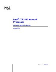
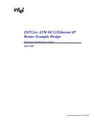
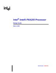
White Paper<strong>Wireless</strong> <strong>Intel</strong> <strong>SpeedStep</strong> ® <strong>Power</strong> <strong>Manager</strong>ApplicationsOS ServicesRadioKernel OS PM PMCommUSB<strong>Power</strong>MgmtProtocol Stack L2/L3AudioProtocol Stack L1HALPMICAudioUSBDriverMSLDriverMSLAT/APEX InterfaceComm FWPM Component PM Enhanced PM Optional OS ComponentFigure 4. Communications Subsystemdevice drivers can be as simple as: enable the clock to Device #1and then enable Device #1, and/or disable Device #2 and thendisable the clock to Device #2. The device drivers must transitionthe devices into the specified power state and prepare thedevices for the next event.The Policy <strong>Manager</strong> also uses the DPI to communicate a newfrequency and a new voltage (that meets system performancerequirements with minimum power consumption) to the <strong>Intel</strong>PXA27x processor’s <strong>Power</strong> I 2 C (PWR_I 2 C) device driver. ThePWR_I 2 C unit within the <strong>Intel</strong> PXA27x processor uses <strong>Intel</strong> DVMto control the physical change to the specified voltage.Frequency can be controlled via <strong>Intel</strong> DFM in conjunction with<strong>Intel</strong> DVM. Each device driver has the flexibility to request thatthe Policy <strong>Manager</strong> change the power state, e.g., the batterydriver can monitor battery thresholds and then use its DPI tonotify the Policy <strong>Manager</strong> of a needed power state change.Each device driver must be designed to be compatible with the<strong>Power</strong> <strong>Manager</strong> software.3.2 Applications Programming Interface (API)Applications that have a dependency on performance can usethe APIs to request the Policy <strong>Manager</strong> to quickly determinea frequency and a voltage that meets immediate performanceneeds with minimum power consumption. The Policy <strong>Manager</strong>uses the DPI to communicate a needed frequency and voltageto the <strong>Power</strong> I 2 C (PWR_I 2 C) device driver. The PWR_I 2 C Unitwithin the <strong>Intel</strong> PXA27x processor uses <strong>Intel</strong> DVM to controlthe physical change to the needed voltage. Frequency can becontrolled via <strong>Intel</strong> DFM in conjunction with <strong>Intel</strong> DVM. Thepower savings that are realized by applications that are optionallyenhanced to use the <strong>Power</strong> <strong>Manager</strong> software supplement thepower savings that are realized with the help of the Idle Profiler,Performance Profiler, and DPIs.3.3 Cellular Processor InterfaceCommunications software, shown on the right side of Figure 4,runs on an <strong>Intel</strong> Cellular Processor. The power managementcomponent of the communications software manages powerfor the communications subsystem and it maintains its ownstate machine. This power management component interfacesto the L1/L2/L3 layers of the communications protocol stackand it has specific run/low-power mode duty cycles associatedwith each of its states for both GSM and GPRS.A physical link connects the application subsystem with thecommunications subsystem. An <strong>Intel</strong> ® Mobile Scalable Link (<strong>Intel</strong> ® MSL) can connect the <strong>Intel</strong> PXA27x processor in theapplications subsystem with an <strong>Intel</strong> CommunicationsProcessor in the communications subsystem. Alternatephysical links could use a UART or a Synchronous Serial Port.Communications device drivers that run on the applicationssubsystem are clients of the <strong>Power</strong> <strong>Manager</strong> software and theoperating system’s native power management component.These communications device drivers receive notifications fromthe <strong>Power</strong> <strong>Manager</strong> software and operating system’s powermanagement component on needed power state transitions.For example, when the OS goes into the Standby power state,these steps are performed:6
<strong>Wireless</strong> <strong>Intel</strong> <strong>SpeedStep</strong> ® <strong>Power</strong> <strong>Manager</strong>White Paper1. The <strong>Power</strong> <strong>Manager</strong> software notifies the communicationsdriver of the need to transition the communicationssubsystem into the Standby power state.2. The communications driver sends a “change to Standby powerstate” message over the <strong>Intel</strong> MSL to the communications powermanagement component of the communications subsystem.3. The communications subsystem enters the Standby powerstate and prepares itself to wake-up the applications subsystemif the communications subsystem transitions into a newstate that requires processing in the applications subsystem.Similarly, for dynamic performance and power scaling, thecommunications device driver is notified about a frequencyand voltage change, and in turn notifies the communicationssoftware of such via the <strong>Intel</strong> MSL.4.0 <strong>Intel</strong> ® PXA27x—Low <strong>Power</strong>EnhancementsThe <strong>Intel</strong> PXA27x processor implements <strong>Wireless</strong> <strong>Intel</strong><strong>SpeedStep</strong> ® Technology in hardware by providing the following:4.1 Reset Sources■■■■■■<strong>Power</strong>-on ResetHardware ResetWatchdog Timer ResetGPIO ResetReset on exit from Sleep modeReset on exit from Deep-Sleep mode4.2 Clock Gating for PeripheralsThe <strong>Intel</strong> PXA27x processor not only allows each of itsperipherals to be independently enabled or disabled, it alsoallows the clock to each peripheral to be independently gatedon or off.4.3 <strong>Power</strong> Modes■■■■Deep Idle mode: This mode can be entered only after thecore frequency has been changed to 13 MHz. Clocks to theCPU are disabled; recovery is through interrupt assertion.Standby mode: All internal power domains except VCC_RTCand VCC_OSC are placed in a low-power mode where stateis retained but no activity is allowed. The clock sources maybe disabled. Some of the internal power domains can bepowered off, and both PLLs are disabled. Recovery is throughexternal and selected internal wake-up events.Sleep mode: All internal power domains except VCC_RTCand VCC_OSC (both are internal supplies) can be poweredoff. All clock sources, except those used by the real-timeclock (RTC) and the power manager unit, are disabled. The<strong>Intel</strong> PXA27x processor’s PWR_EN output pin de-asserts tooptionally disable the external low-voltage power supplies tothe <strong>Intel</strong> PXA27x processor's low-voltage domains. Theremaining power domains are placed in a low-power statewhere state is retained but no activity is allowed. Recoveryis through external and selected internal wake-up events.Because the program counter is invalid, recovery requires asystem reboot (the program counter restarts from 0x0, sothe core begins execution starting at the reset vector).Deep Sleep mode: All internal power domains exceptVCC_RTC and VCC_OSC can be powered off. All clocksources, except those used by the RTC and the powermanager unit, are disabled. The <strong>Intel</strong> PXA27x processor'sPWR_EN output pin de-asserts to optionally disable theexternal low-voltage power supplies to the <strong>Intel</strong> PXA27xprocessor’s low-voltage domains. The <strong>Intel</strong> PXA27xprocessor’s SYS_EN output pin de-asserts to optionallydisable the external high-voltage power supplies to the <strong>Intel</strong>PXA27x processor's high-voltage domains. All power domainsare powered directly from the backup battery pin, VCC_BATT.The remaining power domains are placed in a low-powerstate where state is retained but no activity is allowed.Recovery is through external, and selected internal, wake-upevents. Because the program counter is invalid, recoveryrequires a system reboot (the program counter restarts from0x0, so the core begins execution starting at the reset vector).■■Normal mode: all internal power domains and externalpower supplies are fully powered and functional. Theprocessor clocks are running.Idle mode: Clocks to the CPU are disabled; recovery isthrough interrupt assertion.The <strong>Intel</strong> PXA27x processor provides 37 GPIO inputs that canbe configured as Wake-up events to cause exit from the <strong>Intel</strong>PXA27x processor’s low-power modes (all of the above modesexcept Normal are low-power modes). For example, the <strong>Intel</strong>PXA27x processor has several GPIOs that can act as Wake-upevents when a key is depressed on a Keypad. This wake-up7
White Paper<strong>Wireless</strong> <strong>Intel</strong> <strong>SpeedStep</strong> ® <strong>Power</strong> <strong>Manager</strong>event can awaken the <strong>Intel</strong> PXA27x processor from either theStandby or Sleep low-power modes. Wake-up events couldbe caused by:■■■■■■■■■■KeypressIncoming Voice Phone CallIncoming GPRS DataIncoming SMS MessageHeadset InsertionUSB Cable Insertion and RemovalMMC Insertion and RemovalRTC Wake-upTouchscreen activityShell opening of a “Clam-Shell” phone4.4 Programmable Frequency ChangeManagement (<strong>Intel</strong> DFM) and ProgrammableVoltage Change Management (<strong>Intel</strong> DVM)4.4.1 DFMThe <strong>Intel</strong> PXA27x processor’s core and peripheral clocks are derivedfrom PLLs. The <strong>Intel</strong> PXA27x processor implements <strong>Intel</strong> DFM byallowing the core clock to be configured dynamically by software.The core clock frequency can be changed in several ways:■■■Selecting the 13-MHz clock sourceChanging the core PLL frequencyEnabling or disabling turbo mode or half turbo modeSoftware programs the <strong>Intel</strong> PXA27x processor’s Core ClockConfiguration register (CCCR) to select:■Run Mode to Oscillator Ratio, CCCR[L]—The L-bitdetermines the run frequency by multiplying the externalcrystal oscillator input by L.Software then programs Coprocessor 14, register C6(CLKCFG) to select:■■■■CLKCFG[B]—Fast Bus Mode. If the B-bit is set, thesystem-bus frequency is equal to the run-mode frequencyindicated in CCCR. When the B-bit is cleared, the systembusfrequency is equal to half the run-mode frequencyindicated in the CCCR.CLKCFG[F]—Core Frequency Change. If the F-bit is set,the core PLL is stopped, and then restarted with the newCCCR settings.CLKCFG[T]—Turbo Mode. If the T-bit is set, the CPUoperates at the turbo frequency; when the T-bit is cleared,the CPU operates at the run-mode frequency.CLKCFG[HT]—Half-Turbo Mode. If the HT-bit is set,whether the T-bit is set or clear, the CPU operates at theturbo frequency divided by two; when the HT-bit is clear,and the T-bit is clear, the CPU operates at the run-modefrequency; when HT is clear, and T is set, the CPU operatesat the turbo frequency.An automatic frequency change sequence is initiated whensoftware sets CLKCFG[F]. This sequence establishes the valuesin CCCR and the selected modes in CLKCFG.4.4.2 DVMThe <strong>Intel</strong> PXA27x Processor implements <strong>Intel</strong> DVM throughits Voltage <strong>Manager</strong>. The Voltage <strong>Manager</strong> provides voltagemanagement through use of an I 2 C unit (PWR_I 2 C) that isdedicated to communication with an external PMIC regulator,and through use of a Voltage Change Sequencer.When software initiates a voltage-change mode, the VoltageChange Sequencer can automatically send commands via thePWR_I 2 C unit to an external PMIC regulator. The sequencercan send up to 32 commands, which can be categorized asdynamic commands and static commands:■■Turbo Mode to Run Mode Ratio, CCCR[2N]—The N-bitdetermines the turbo frequency by multiplying the runfrequency by 2N.Alternate Memory Controller Clock Selection,CCCR[A]—If the A-bit is set, the memory controller’s clockfrequency is the same as that of the system bus; if the A-bitis clear, the memory controller’s clock frequency is as shownin Table 1, next page.■■Dynamic commands are executed when the core is running.Static commands are executed after clocks to theprocessor are disabled.The <strong>Intel</strong> PXA27x processor uses its <strong>Power</strong> <strong>Manager</strong> GeneralConfiguration Register (PCFR), <strong>Power</strong> <strong>Manager</strong> Voltage changeControl Register (PVCR), and <strong>Power</strong> <strong>Manager</strong> I 2 C CommandRegister File (PCMDx) to define and control a voltage changesequence:8
<strong>Wireless</strong> <strong>Intel</strong> <strong>SpeedStep</strong> ® <strong>Power</strong> <strong>Manager</strong>White Paper■■■■Frequency/Voltage Change, PCFR[FVC]—If the FVC bitis set, a frequency change sequence (DFM) also triggers avoltage change sequence (DVM).Read Pointer, PVCR[RP]—The read pointer field in thePVCR points to the PCMD register location that contains acommand or the first command of multiple commands thatare to be sent to the external regulator via the PWR_I 2 C. Thecommand sequence can start from any one of 32 PCMDregisters. After a command is sent out, the Read Pointerincrements to point to the next PCMD register location. Theread pointer is not incremented if the current command is thelast command, as indicated by PCMD[LC] set.Delay Command Execution, PCMD[DCE]—If the DCE bitis set in the current PCMD, a counter (set by the commanddelay bits in PVCR) waits for a programmable number of13-MHz processor-oscillator cycles before continuingexecution of the command. This is useful if a longer periodbetween commands is required.Multi-Byte Command, PCMD[MBC]—If the MBC bit isset, the voltage change sequencer continues sending byteswith no delay or handshaking with the power manager unituntil a command with the MBC bit clear is executed.■Last Command, PCMD[LC]—If the LC bit is clear, thevoltage-change sequencer expects the PCMD register at thenext higher address to contain an additional command. If theLC bit is clear in PCMD31, the PVCR Read Pointer rolls overto PCMD0 after executing the command in PCMD31. Whenthe LC bit is set, the Voltage Change Sequencer considersthe current command to be the last one and finishes afterexecution completes. Each voltage change commandsequence must be terminated by setting the LC bit of thelast command in the sequence. The PVCR Read Pointer isnot incremented if the LC bit is set.4.4.3 COUPLING VOLTAGE CHANGEWITH FREQUENCY CHANGEA frequency change (clock source change or core PLLfrequency change) may be used to change the frequencyof the core, system bus, memory controller, and LCD controllerto a value not available with turbo or fast-bus modes. Thisfrequency change can be coupled with a voltage change bysetting PCFR[FVC]. Similarly, a voltage change can be coupledwith a change to or from fast-bus mode.4.5 Programmable Operating FrequenciesThe <strong>Intel</strong> PXA27x processor’s programmable operatingfrequencies are shown in Table 1.Core RunFrequencyCLKCFG[T]Core TurboFrequencyCLKCFG[T]CLKCFG[HT]CCCR[L]CCCR[2N]System BusCLKCFG[B]CLK_MEM(Memory Controller)CCCR[A]SDCLKSDRAM ClocksMDREFR[KxDB2] ††Synchronous FlashMDREFR[K0DB4]MDREFR[K0DB2]LCD91.0 † 0 — — 0 7 2 45.0 0 91.0 0 45.0 1 22.5 1104.0 0 104.0 1 0 8 2 104.0 1 104.0 1 104.0 0 52.0 0156.0 0 156.0 1 1 8 6 104.0 1 104.0 1 104.0 0 52.0 0104.0 0 312.0 1 0 8 6 104.0 1 104.0 1 104.0 0 52.0 0208.0 0 208.0 1 0 16 2 208.0 1 208.0 1 104.0 1 52.0 1208.0 0 312.0 1 0 16 3 208.0 1 208.0 1 104.0 1 52.0 1208.0 0 416.0 1 0 16 4 208.0 1 208.0 1 104.0 1 52.0 1208.0 0 520.0 1 0 16 5 208.0 1 208.0 1 104.0 1 52.0 1208.0 0 624.0 1 0 16 6 208.0 1 208.0 1 104.0 1 52.0 11 91.01 52.01 52.01 52.0X 104.0X 104.0X 104.0X 104.0X 104.0† L=7 (Core = 91.0 MHz) must be strictly used as the bootup frequency and immediately reconfigured to one of the other frequency points.†† KxDB2 represents K1DB2 and K2DB2Table 1. Clock Frequencies9
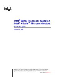
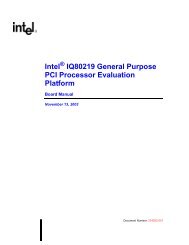
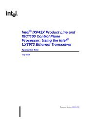
White Paper<strong>Wireless</strong> <strong>Intel</strong> <strong>SpeedStep</strong> ® <strong>Power</strong> <strong>Manager</strong>800000700000DHRYSTONES/SEC6000005000004000003000002000001000000CORE/PX/SDCLKDhrystones/secProcessing BoundFrequency scaling despiteconfigured core speedHigher is Better208, 208, 208, 208, 520, 520, 520, 520,104, 208, 104, 208, 208, 104, 208, 104,52 52 104 208 52 52 208 104269778 269778 269778 269778 674442 674443 674443 674444Figure 5. Dhrystone/sec vs. Core/PX/SDCLK180160140120100MB/SEC806040200CORE/PX/SDCLKMB/sec208, 520, 208, 520, 520, 208, 208, 520,104, 104, 104, 104, 208, 208, 208, 208,52 52 104 104 52 52 104 10468.9 69.1 79.9 80.6 80.9 81.4 116.1 126.3Figure 6. MB/sec vs. Core/PX/SDCLK5.0 Workload Characterization for<strong>Intel</strong> DFM and DVMMost software applications/workloads can be generalized intothree main categories:■■■■CPU (compute) bound applicationsMemory bound applicationsI/O bound applicationsCPU and Memory bound applications5.1 CPU Bound ApplicationsAn application is generally considered CPU-bound when mostof its execution time is spent on computation, using the dataand instructions loaded in D-cache and I-cache. Schedulinginstructions suitable to the underlying processor architecture(reducing stalls) can potentially increase performance of CPUboundapplications. These applications tend to keep the CPUbusy all of the time and the processor’s idle time is negligible.An increase in processor frequency (and in turn voltage) helpsto increase the performance of these applications. As anexample, Dhrystone is a purely CPU bound workload and asshown in Figure 5, the performance is a linear function of CPU(core) frequency. In order to meet performance requirements, itis essential to have these applications run at the maximumpossible frequency. This information is very critical for aperformance-optimizing policy manager.5.2 Memory Bound ApplicationsSome applications that work on large data blocks (greater thanthe cache size) usually have to access data outside of thecaches, and become bound by the memory or the system busspeed. These applications, such as a memory copy, move largeblocks of data and tend to generate significant memory traffic,with most CPU cycles lost waiting for data. In such cases,performance does not improve (see Figure 6) even if thecore’s speed is increased, since the performance is a functionof the memory speed. This information is very critical for aperformance-optimizing policy manager.10
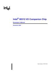
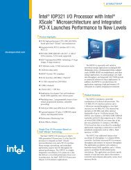
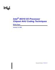
<strong>Wireless</strong> <strong>Intel</strong> <strong>SpeedStep</strong> ® <strong>Power</strong> <strong>Manager</strong>White Paper25WMV FPS2015105MEMBoundCPUBoundMEMBoundCPUBoundMEMBoundHigher is Better0CORE/PX/SDCLKWMV FPS/sec208, 208, 520, 208, 520, 520,104, 104, 104, 208, 104, 208,52 104 52 104 104 1048.7 10.3 14.1 15.1 18.1 21.5Knowledge relevant to <strong>Power</strong> Management from system or application perspectiveFigure 7. WMV FPS vs. Core/PX/SDCLK5.3 I/O Bound ApplicationsApplications that are waiting on some I/O (peripheral) devicefor data are considered I/O bound. An example would be anEthernet driver waiting for data from the network.5.4 CPU and Memory Bound ApplicationsMany applications have performance demands that vary overtime. At a given instant they could be either CPU (compute)bound or memory bound. Multimedia applications thatundertake a large amount of computations as well as work onlarge data blocks fall in this category. The characteristics ofthese multimedia applications show that performance isbounded by both memory and CPU speed. For these typesof workloads, accurate prediction or estimation of thecharacteristics yields a better power policy. For example, avideo player is a CPU and memory bound type of application.Its performance is plotted as a function of the core andmemory frequency in Figure 7.6.0 Idle ProfilerThe Idle Profiler provides CPU usage and operating system idleinformation to the <strong>Power</strong> <strong>Manager</strong> software. Figure 8 shows theoperating system’s idle thread providing input to the Idle Profiler.Since the idle thread is executed when the OS is not busy (notexecuting any code), it is one of the preferred choices toprovide CPU usage information. However, since the idle threadonly executes when there are no tasks ready to run, theinformation is only provided when the CPU is used less than100 percent of the time. In cases where CPU usage is less than100 percent of the time, but still very high, the ISR can be usedto provide CPU usage information to the Idle Profiler.7.0 Performance ProfilerSystem workload does not remain static at any given time.So, dynamic workload characterization is essential to theoptimization of system performance at minimum powerdissipation. The Performance Profiler monitors systeminformation and maintains a system state. At any given time,the Policy <strong>Manager</strong> can direct the Performance Profiler toreturn the current system state. Since the Performance Profileris event driven, it can automatically alert the Policy <strong>Manager</strong>when the system state changes.In order to achieve dynamic scaling for power and performancebased on dynamic characterization of CPU bound, memorybound, or CPU and memory bound workloads, the PerformanceProfiler monitors the <strong>Intel</strong> PXA27x processor’s PerformanceMonitoring Unit (PMU) as shown in Figure 9, next page.OS IdleThreadISRCPUUtilizationLogicPredictionLogicStateDeterminationPMInterfacePM Interface<strong>Power</strong> <strong>Manager</strong> Idle ProfilerFigure 8. Idle Profiler, <strong>Power</strong> <strong>Manager</strong> Software11
White Paper<strong>Wireless</strong> <strong>Intel</strong> <strong>SpeedStep</strong> ® <strong>Power</strong> <strong>Manager</strong>Read PMUEventsCalculatethe StatisticDeterminethe StateInterfacewith PM<strong>Power</strong> <strong>Manager</strong> Idle ProfilerFigure 9. Performance ProfilerThe PMU tracks processor events as described in Table 2. ThePerformance Profiler also monitors the status registers ofperipheral devices such as the <strong>Intel</strong> PXA27x processor’s LCDController. This monitoring allows the Performance Profiler todynamically characterize the system state.8.0 Policy <strong>Manager</strong>The Policy <strong>Manager</strong> defines power states and maps them topower modes of the <strong>Intel</strong> PXA27x processor and/or <strong>Wireless</strong><strong>Intel</strong> Communications Processor. If a power state is native tothe operating system, the Policy <strong>Manager</strong> uses the nativepower state and the operating system’s interface to the DPIsto transition the system into the specified power state. If thepower state is not native to the operating system, the Policy<strong>Manager</strong> creates the power state and uses the DPIs totransition the system into the specified power state.The Policy <strong>Manager</strong> uses device driver inputs, applicationworkload inputs (optional), Idle Profiler inputs, and PerformanceProfiler (system workload) inputs to define the system’s powerpolicy. Alternatively, an OEM can use these inputs to define itsown power policy.The <strong>Power</strong> <strong>Manager</strong> software provides an infrastructure to thedevice drivers for state changes, frequency changes, and voltagechanges. Using this infrastructure, the <strong>Power</strong> <strong>Manager</strong> softwarenotifies the client drivers of these changes either directly orthrough the operating system’s power management services.A system that is enabled by the <strong>Power</strong> <strong>Manager</strong> software willalways maintain a predefined operating point as part of a globalvariable, namely IPMOperatingPoint = [State, Voltage, Frequency,Frequency2, Frequency3]Information SourcePMU RegistersDescription of EventInstruction cache-missInstruction cache cannot deliverinstructionData dependency stallInstruction TLB missData TLB missInstruction executedNumber of Stalls an number of times thestall occurs due to D-Cache buffer full(every cycle condition is present)Data cache accessData cache-missData cache write-backSoftware changed the PCUsage for CharacterizationInstruction traffic and CPI estimation andcache locality%Memory usePage locality%CPU UsedData traffic / Data access congestion /Congestion rate and congestion lengthsData access rate, memory bound,%Memory useData traffic and %Memory useData trafficNumber of function callsTable 2. <strong>Intel</strong> ® PXA27x Processor’s Performance Monitoring Unit (PMU)12
<strong>Wireless</strong> <strong>Intel</strong> <strong>SpeedStep</strong> ® <strong>Power</strong> <strong>Manager</strong>White PaperWhere:■■■■■State = Processor StateVoltage = Processor Core VoltageFrequency1 = Processor Core FrequencyFrequency2 = System Bus FrequencyFrequency3 = SDCLK FrequencyFor example, the state of the <strong>Intel</strong> PXA27x processor could beRun, Sleep, Standby, Idle, or Deep Idle.Similarly, the voltage and frequency can take on any of the valuessupported by the <strong>Intel</strong> PXA27x processor. At any given instant,the output of the Policy <strong>Manager</strong> sets IPMOperatingPoint to theoptimum values that achieve the required performance at thelowest power dissipation.9.0 Device Drivers Interface9.1 OverviewThe <strong>Power</strong> <strong>Manager</strong> software’s Device Interface Layer workswith the device drivers and the <strong>Power</strong> <strong>Manager</strong> software’sPolicy <strong>Manager</strong> as shown in Figure 10.Since many operating systems have some level of native powermanagement infrastructure, the <strong>Power</strong> <strong>Manager</strong> softwareinterfaces with this native infrastructure wherever possible. If theoperating system does not have a native power managementinfrastructure, the <strong>Power</strong> <strong>Manager</strong> software adds managementinfrasturcture. The <strong>Power</strong> <strong>Manager</strong> software ports the DriverInterface Layer of each operating system, providing a level ofabstraction that allows the Policy <strong>Manager</strong> to be decoupledfrom direct driver interaction.The following sections describe the generic architecture ofDriver interaction. The implementation details differ over variousoperating systems, and are addressed in separate OS-specificdocumentation.9.2 RegistrationThe <strong>Power</strong> <strong>Manager</strong> software has the ability to notify driverswhen power parameters change. This notification allows adriver to prepare for the pending transition, or to veto thetransition if necessary. During registration, the driver mustsupply a callback function either to the existing infrastructure ordirectly to the <strong>Power</strong> <strong>Manager</strong> software if no such infrastructureexists. The driver also must inform the <strong>Power</strong> <strong>Manager</strong> softwareof the target device's frequency and state sensitivity so that the<strong>Power</strong> <strong>Manager</strong> software will only notify the driver of a pendingstate transition when applicable.9.3 Device Driver Interface LayerBased on the implicit direction of flow, there are two categoriesof Driver interface types:■■<strong>Power</strong> <strong>Manager</strong> software-to-Driver interface: Thisinterface defines a set of routines that provide inputs to agiven registered driver. These routines allow the <strong>Power</strong><strong>Manager</strong> software to notify a registered driver of its intentionto alter the system power state in some way, such as enteringStandby mode or Idle mode. Drivers must be able to vetothe <strong>Power</strong> <strong>Manager</strong> software's request to perform a powerparameter transition if doing so causes undesirable behavior.Driver-to-<strong>Power</strong> <strong>Manager</strong> software interface: Thisinterface defines a set of routines that a registered driver canuse to provide unique information regarding the targetdevice’s loading and power state to the <strong>Power</strong> <strong>Manager</strong>software. This information can help the <strong>Power</strong> <strong>Manager</strong>software make informed decisions in determining the optimalsystem power state. At a minimum, a registered driver mightonly provide a stub for these routines.<strong>Power</strong> <strong>Manager</strong> Policy <strong>Manager</strong><strong>Power</strong> <strong>Manager</strong> Device Driver Interface LayerOS <strong>Power</strong> Management InfrastructureDriver[0]Driver[1]Driver[1]Driver[n-1]Figure 10. Device Drivers Interface, <strong>Power</strong> <strong>Manager</strong> Software13
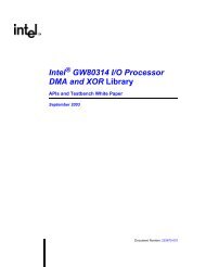
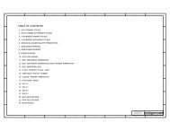
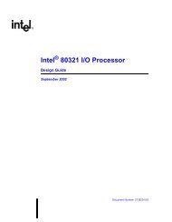
White Paper<strong>Wireless</strong> <strong>Intel</strong> <strong>SpeedStep</strong> ® <strong>Power</strong> <strong>Manager</strong>It is important that all drivers maintain their own device powerstate management. The drivers must at least be able to monitortheir own activity and self-manage their own state, such asturning off the peripheral device when it makes sense andinforming the <strong>Power</strong> <strong>Manager</strong> software of the transition. The<strong>Power</strong> <strong>Manager</strong> software tracks the state of each driver, butdoes not mandate the device's state management.9.3.1 DEVICE POWER STATESSince many operating systems currently have some level ofdevice power management, the Device Driver Interface Layertranslates an OS-specific device state into an appropriate<strong>Power</strong> <strong>Manager</strong> software-specific state. If an operating systemdoes not supply power management device states, the devicedrivers use the power states created by the <strong>Power</strong> <strong>Manager</strong>software. When a registered driver transitions its device's powerstate, the driver must inform the <strong>Power</strong> <strong>Manager</strong> software ofthis transition. <strong>Power</strong> <strong>Manager</strong> software device states areshown in Table 3.STATEOnOffLow <strong>Power</strong>DESCRIPTIONThe device is fully powered up and fullyfunctional.The device is off.The device is on, but is in a reduced powerstate. Depending on the device there could beseveral of these low-power states.Table 3. Device States9.3.2 DEVICE STATE SENSITIVITYAs part of the driver’s registration, the driver must report to the<strong>Power</strong> <strong>Manager</strong> software what the device’s sensitivity is to allsupported processor modes. If a driver reports that it is sensitiveto a given state, the <strong>Power</strong> <strong>Manager</strong> software notifies the driverof an impending state transition before the <strong>Power</strong> <strong>Manager</strong>software makes the state transition.9.3.3 DEVICE FREQUENCY SENSITIVITYAs part of a driver’s registration, the driver must inform the<strong>Power</strong> <strong>Manager</strong> software as to whether or not the driver requiresnotification when the Policy <strong>Manager</strong> intends to scale thedevice’s frequency and/or voltage. For example, Table 1 showsthat when the Policy <strong>Manager</strong> intends to scale the <strong>Intel</strong> PXA27xprocessor’s Core Run Frequency from 208 MHz to 104 MHz,other <strong>Intel</strong> PXA27x processor frequencies (e.g., System Bus,Memory Controller, LCD Controller) must be scaled as well.10.0 <strong>Power</strong> <strong>Manager</strong> Software-AwareApplication Interface (Optional)10.1 OverviewApplications can be easily enhanced to provide their performance/processing requirements (cycles, deadlines, etc.), to the <strong>Power</strong><strong>Manager</strong> software, thus making frequency change and voltagechange scheduling simpler and more effective. For example,consider a mobile platform that uses the <strong>Intel</strong> PXA27x processorto control a small-sized display. For an MPEG4 video applicationto decode and display 30 fps, the <strong>Intel</strong> PXA27x processor canrun at its maximum possible frequency and voltage so thatsignificant idle time exists during the execution bursts that areneeded to service the application, as shown in Figure 2. TheIdle Profiler alone would either not detect this idle time (if it isvery small) or would incur a latency in detecting the idle time.Optionally, if the application is slightly enhanced to convey theidle time information to the <strong>Power</strong> <strong>Manager</strong>, the Policy Managecan make good decisions to reduce power dissipationduring the idle time.10.2 Application Programming InterfaceThe Applications Programming Interface (API) is shown inFigure 11 below.App[0]App[1]App[n-1]<strong>Power</strong> <strong>Manager</strong> Application Interface Layer<strong>Power</strong> <strong>Manager</strong> Policy <strong>Manager</strong>Figure 11. Applications Programming Interface14
<strong>Wireless</strong> <strong>Intel</strong> <strong>SpeedStep</strong> ® <strong>Power</strong> <strong>Manager</strong>White PaperWaitingRunning(CPU)MemoryBoundMemoryand CPUBoundFigure 12. Application <strong>Power</strong> StatesThe API is designed to allow communication between thePolicy <strong>Manager</strong> and each <strong>Power</strong> <strong>Manager</strong> software-awareapplication. Applications must register with the <strong>Power</strong> <strong>Manager</strong>software and provide power state information to the <strong>Power</strong><strong>Manager</strong> software.10.3 Application <strong>Power</strong> StatesAt any given instant, each application must be in one of fourpower states as shown in Figure 12:■■■■Running—This state is the most common power state. Anapplication is running/executing instructions and all neededdata is available, i.e., the application does not expect tohave any data-stalls. A Dhrystone application is an exampleof this CPU bound power state.Waiting—An application is polling a peripheral and is waitingfor a response, or an application is idling. An application thatis waiting for network data is an example of this I/O boundpower state.Memory Bound—An application is moving large blocks ofdata. A Memory-Copy (MEMCPY) operation is an example ofthis Memory bound power state.Memory and CPU Bound—An application is running acomplex algorithm on blocks of memory data. A video gameis an example of this Memory and CPU Bound power state.11.0 Example <strong>Power</strong> <strong>Manager</strong> Softwarefor the <strong>Intel</strong> ® PXA27x Processortypedef enum {IPMErr = 0,IPMNoErr =1} IPMStatus;typedef enum {Run,M13,Standby,Sleep} CPUState;typedef struct _IPMState {CPUState CPUState;// Current Processor ModeUINT32 CPUVoltage;// Current Core Voltage * 100UINT32 CPUFrequency;// Current Core Frequency * 100UINT32 PXFrequency;// Current Bus Frequency * 100UINT32 SDClk0Frequency;// Current SDCLK0 Frequency * 100UINT32 SDClk1Frequency;// Current SDCLK1 Frequency * 100UINT32 SDClk2Frequency;// Current SDCLK2 Frequency * 100} IPMState;typedef enum {Core,MemClk,LcdClk} ClksEnum;15
White Paper<strong>Wireless</strong> <strong>Intel</strong> <strong>SpeedStep</strong> ® <strong>Power</strong> <strong>Manager</strong>const UINT32 FreqArray[][3] = {// Core, Mem, LCD62400, 20800, 10400,52000, 20800, 10400,41600, 20800, 10400,31200, 20800, 10400,20800, 20800, 10400,31200, 10400, 5200,15600, 10400, 5200,10400, 10400, 5200};typedef struct _FreqStruct {UINT32 Core;UINT32 Mem;UINT32 Lcd;} FreqStruct;typedef FreqStruct FreqArray [sizeof(BvdFreqArray)/sizeof(UINT32)/(LcdClk+1)];typedef enum {Off,On,Low<strong>Power</strong>} DevStatesEnum;typedef struct _IPMDeviceInfo {char DeviceId;// Device IdentifierDevStatesEnumDeviceState;// Current State of Device} IPMDeviceInfo;typedef struct _IPMDriverInfo {USHORT DriverHandle;// Id for a registered driverIPMDeviceInfo Devices[8];// Max of 8 deviceschar NumDevices;// indicates #devices managedchar *CallBack; // callback functionDriverFreqSensitivity FreqSensitivity; // 32-bit bitfieldDriverStateSensitvity StateSensitvity; // 32-bit bitfield} IPMDriverInfo;typedef UINT32 DriverFreqSensitivity; // bit field based onFreqArraytypedef UINT32 DriverStateSensitvity; // bit field based onCPUState12.0 SummaryFirst available in the <strong>Intel</strong> PXA27x processor family, <strong>Wireless</strong> <strong>Intel</strong><strong>SpeedStep</strong> ® Technology provides the ability to dynamically adjustthe power and performance of the processor based on CPUdemand. This can result in a significant decrease in powerconsumption for wireless handheld devices to increase standbyand talk-time. <strong>Wireless</strong> <strong>Intel</strong> <strong>SpeedStep</strong> Technology advances thecapabilities of functions already built into the <strong>Intel</strong> XScalemicroarchitecture by incorporating three new low-power statesand using advanced <strong>Wireless</strong> <strong>Intel</strong> <strong>SpeedStep</strong> <strong>Power</strong> <strong>Manager</strong>Software to intelligently manage the power and performanceneeds for the end user. The technology is able to change bothvoltage and frequency on-the-fly, saving additional power whilestill providing the necessary performance to run rich applications.For more information, visit the <strong>Intel</strong> Web site at: developer.intel.comPerformance tests and ratings contained within this document are measured using specific computer systems and/or components and reflect theapproximate performance of <strong>Intel</strong> ® products as measured by those tests. Any difference in system hardware or software design or configurationmay affect actual performance. Buyers should consult other sources of information to evaluate the performance of systems or components theyare considering purchasing. For more information on performance tests and on the performance of <strong>Intel</strong> products, referencewww.intel.com/procs/perf/limits.htm or call (U.S.) 1-800-628-8686 or 1-916-356-3104*Other names and brands may be claimed as the property of others.<strong>Intel</strong>, the <strong>Intel</strong> logo, and <strong>Intel</strong> <strong>SpeedStep</strong> are trademarks or registered trademarks of <strong>Intel</strong> Corporation or its subsidiaries in the United States and othercountries.Copyright © 2004 <strong>Intel</strong> Corporation. All rights reserved. 0304/MS/MD/PDF t Please Recycle 300577-001