Step-by-Step Tutorial For Using LinkSprite UART- WIFI Module ...
Step-by-Step Tutorial For Using LinkSprite UART- WIFI Module ...
Step-by-Step Tutorial For Using LinkSprite UART- WIFI Module ...

You also want an ePaper? Increase the reach of your titles
YUMPU automatically turns print PDFs into web optimized ePapers that Google loves.
<strong>Step</strong>-<strong>by</strong>-<strong>Step</strong> <strong>Tutorial</strong> <strong>For</strong><strong>Using</strong> <strong>LinkSprite</strong> <strong>UART</strong>-<strong>WIFI</strong> <strong>Module</strong> ModelLS_<strong>UART</strong>_<strong>WIFI</strong>Page 1 of 12
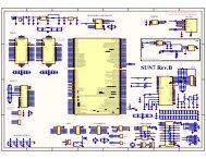
Hardware needed A desktop/laptop PC with WiFi adaptor A WiFi router This Uart-Wifi module model number LS_<strong>UART</strong>_<strong>WIFI</strong> with antenna A Uart-serial port converter and cable. In this tutorial, an Arduino board is usedas a <strong>UART</strong>-USB converter. Other serial interface, e.g. RS-232 is okay. Serial port cable. In this tutorial, USB cable is used.Hardware Connection Use an Arduino board as a <strong>UART</strong>-USB converter. The MCU is removed. Only theFT232RL is used in this test. The schematic is shown below. Use an adaptor to connect the WiFi module to the Arduino board. Connect one end of a USB cable to the Ardunio board, and the other end to a PC. Connect the antenna to the WiFi module.Page 2 of 12
Test Procedure<strong>Step</strong> 1: Open X-CTU. Find which serial port the WiFi module is connected to. Inthis tutorial, it is COM4.Note: <strong>For</strong> some reason, only COM1~COM4 is supported in the test tool software.If you find port COM5 or up in X-CTU, please change to a different COM port. .<strong>Step</strong> 2: Open the server software. Select TCP, and port number 6000, and click onStart. Before TCP connection is connected, the Remote IP and remote Port bothshow “not connected”.Page 5 of 12
<strong>Step</strong> 3: In your PC start/run, type cmd and return. Find out your IP configuration <strong>by</strong>ipconfig. You can find the IP address, subnet mask, and default gateway. Thisinformation will be used in the Client configuration.Page 6 of 12
<strong>Step</strong> 4: Open the Client software. First click on Close under Serial Configure.Select correct serial port number that is found out in X-CTU. Select the baud rate.Then click on Open. This opens the serial port.<strong>Step</strong> 5: Click on Scan under Control. The found WiFi network is shown in the outputwindow. Record the channel number, BSSID, and SSID, which will be used in theconfiguration.Page 7 of 12
If you cannot find WiFi network, try the following1. close serial port, select correct port number, and open it. Sometimes you need torepeat it for a few times2. Reset <strong>by</strong> clicking on Reset under Control.3. Unplug the USB cable and plug it again. This is a hard reset. After it, go back to1.Note. If you open multiple client test tool, you can only open the serial port in oneclient.<strong>Step</strong> 6: Configure the module setting <strong>by</strong> clicking on Parameters. Set the channelnumber, BSSID, SSID from <strong>Step</strong> 5. Select TCP in data type. Set the local IP, which isthe IP address of the WiFi module. You can use any valid IP address in your WiFi subnetwork. Set the Gateway to the Default Gateway from <strong>Step</strong> 3. Set the Server IP to theIP Address from <strong>Step</strong> 3. Set the Mask to the Subnet Mask from <strong>Step</strong> 3.Select service port that is same as the port number in the Server software.If you WiFi network has authentication protection, such as WEP, then set the WEPlength, and the Key. This key is your password to access your WiFi network.Page 8 of 12
Set the System parameters, including baud rate. This baud rate must be same as theone set in the Server.Before you save your parameters, do not forget to check the box before eachparameter. Only the checked parameters will be saved. Now click on Save tosave the parameters to the module.<strong>Step</strong> 7: Join a WiFi network <strong>by</strong> clicking on Join. Select which group of parametersto be used. If successful, the output window will show “Join successfully”.Otherwise, the output window will show “leave bss”.<strong>Step</strong> 8: Connect TCP <strong>by</strong> clicking on “Connect”. If successful, the output windowwill show “Connect successfully”. Otherwise, the output window will show “TCP isdisconnected”. After it is connected, the Server software will show the remote IPPage 9 of 12
and port, which are the IP address and port of the WiFi module.Note: try a few times if you have difficulty connecting the TCP. One possiblecause is the power supply of the USB cable to the WiFi module is not enough. Ifso, use a separate DC power supply to drive the WiFi module.<strong>Step</strong> 9: Send text message from the Client or the Server. The Server or the Clientwill show the text message that it receives from the sender.<strong>Step</strong> 10:Test above procedure using X-CTU.First set <strong>UART</strong> parameters: baud=115200, flow control=No, Data bits=8,Parity=None, Stop bit=1.Example : Scan networkCompose HEX message AA 84 00 04 13 00 31 04 55 00 00 00 00 00 00, click onSend Data. The returned message shows that the WiFi network Ej.mtnview is found.Page 10 of 12
<strong>For</strong> details of the UATT data format and protocol, please refer to the user’s manual.Note: Another easier way how to do the programming is to look at the serial datawindow in the Client software. All the sent and received commands in theCmd/Msg window are interpreted in serial data window in HEX data format.Page 11 of 12
<strong>LinkSprite</strong> Technologies, Inc.Add: 1410 Cannon Mountain Dr, Longmont, CO 80503Tel: 720-204-8599Email: sales@linksprite.comTechnical support: support@linksprite.comWeb: www.linksprite.comPage 12 of 12