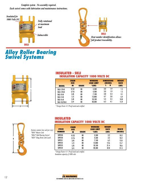
Complete system - No assembly required.Each swivel comes with lubrication and maintenance instructions.Insulated for1000 Volts DC.Fully rotationalat maximumloadSKlISubmersibleAlloy Roller BearingSwivel SystemsSKlIHeat number identification allowsfull product traceability.insulated - SKLIinsulation capacity 1000 volts DCLMODELskli-7/8-8skli-7/8-8skli-10-8skli-13-8skli-16-8skli-18/20-8CHaiNSIZEIN9/325/163/81/25/83/4GRADE808080808080WORKINGLOAD LIMIT*(LBS)3,5004,5007,10012,00018,10028,300DIMENSIONS(INCHES)l d3.0 1.93.0 1.93.8 2.34.7 3.05.4 3.56.3 4.1WEIGHTeach(LBS)1.51.53.16.410.815.9D* Design factor 4:1 Proof tested and certified.insulatedInsulation capacity 1000 volts dcRSystems contain (one each per size):“SKO” Master Link“SKLI” Ball Bearing Swivel“SKN” Sling Hook with LatchStocknumber589350589350589351589352589353589354CHaiNSIZEIN9/325/163/81/25/83/4GRADE808080808080* Design factor 4:1 Proof tested and certified.Insulation capacity of 1000 voltsWORKINGLOAD LIMIT*(LBS)3,5004,5007,10012,00018,10028,300WEIGHTeach(LBS)3.23.26.312.621.432.8Reach(inches)10.210.213.015.718.621.312WARNINGSEE WARNINGS AND USE LIMITATIONS ON PAGES 26-36
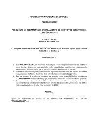
Extra width (B)inside allowsbetter fit onlarge CraneHooksMHeat numberidentificationallows full producttraceability.Engineered flateliminates mix ormatch problems.Heat numberidentificationallows fullproducttraceability.MTExtra wide forbetter fit oncrane hooks.Alloy Master LinksOBLONG MASTER LINKS, GRADE 100 - TYPES M & MTDESIGN FACTOR 5: FOR USE WITH WIRE ROPEL 1LLldDBDBTRADESIZEWorkingLoadLimit *(Lbs)DIMENSIONS(INCHES)WEIGHT(LBS)IN MM MODEL GRADE L B D L1 I b d3/8 11 M-6-10 100 3,300 3.9 2.4 0.43 - - - - 0.441/2 14 M-86-10 100 7,000 4.7 2.8 0.55 - - - - 0.885/8 17 M-108-10 100 11,400 5.5 3.1 0.67 - - - - 1.83/4 19 M-13-10 100 12,300 5.9 3.5 0.75 - - - - 2.27/8 22 M-1310-10 100 17,200 6.3 3.7 0.87 - - - - 3.31 25 M-1613-10 100 29,900 7.5 4.3 1.0 - - - - 5.11 1/4 30 M-19-10 100 35,200 7.9 4.7 1.2 - - - - 7.71 3/8 34 M-2016-10 100 45,300 9.4 5.5 1.3 - - - - 11.71 1/2 38 M-2220-10 100 68,000 9.8 5.9 1.5 - - - - 16.11 5/8 40 M-2622-10 100 70,400 9.8 5.9 1.6 - - - - 17.21 5/8 42 M-2620-10 100 70,400 9.8 5.9 1.7 - - - - 17.21 3/4 45 M-32-10 100 84,900 11.8 7.1 1.8 - - - - 26.42 50 M-3226-10 100 102,600 11.8 7.9 2.0 - - - - 33.12 1/4 55 M-3632-10 100 143,100 13.8 7.9 2.2 - - - - 46.32 1/2 60 M-4536-10 100 160,000 14.8 8.3 2.4 - - - - 57.32 3/4 70 M-90T-10 100 220,200 17.7 9.8 2.8 - - - - 94.83 1/4 80 M-125T-10 100 275,300 17.7 10.2 3.1 - - - - 125.63/4 19 MT-6-10 ** 100 11,000 5.9 3.5 0.75 10.6 4.7 2.8 0.55 4.07/8 22 MT-8-10 ** 100 17,600 6.3 3.7 0.87 11.8 5.5 3.1 0.67 6.61 25 MT-9-10 100 21,300 7.5 4.3 1.0 13.4 5.9 3.5 0.75 9.51 1/4 30 MT-10-10 ** 100 35,200 7.9 4.7 1.2 14.2 6.3 3.7 0.87 14.31 5/8 40 MT-13-10 ** 100 57,200 9.8 5.9 1.6 17.7 7.9 4.7 1.2 31.32 50 MT-16-10 ** 100 77,000 11.8 7.9 2.0 19.7 7.9 4.7 1.3 50.72 1/4 55 MT-20-10 ** 100 110,100 11.8 7.9 2.2 21.7 9.8 5.9 1.6 69.42 1/2 60 MT-22-10 100 165,100 13.8 7.9 2.4 24.0 10.2 5.5 1.8 101.42 3/4 70 MT-26-10 100 220,200 17.7 9.8 2.8 28.7 11.0 6.3 2.0 156.53 1/4 80 MT-32-10 100 275,300 17.7 10.2 3.1 29.5 11.0 6.3 2.2 200.6bWARNINGSEE WARNINGS AND USE LIMITATIONS ON PAGES 26-36* Design Factor 5:1, Proof tested to 2 times Working Load Limit** Subassemblies Contain Engineered FlatsWorking Load Limit for Single Leg SlingM & MT master link series replace the O & OT master link series13