Hunter Control System Design Guide - Hunter Industries
Hunter Control System Design Guide - Hunter Industries
Hunter Control System Design Guide - Hunter Industries
- No tags were found...
You also want an ePaper? Increase the reach of your titles
YUMPU automatically turns print PDFs into web optimized ePapers that Google loves.
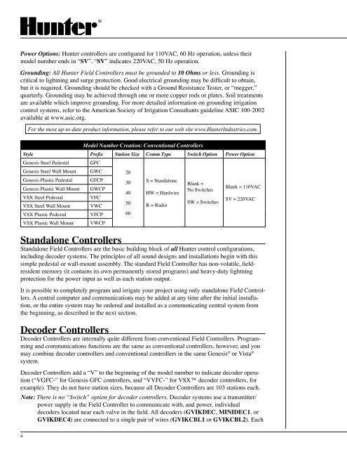
Power Options: <strong>Hunter</strong> controllers are configured for 110VAC, 60 Hz operation, unless theirmodel number ends in “SV”. “SV” indicates 220VAC, 50 Hz operation.Grounding: All <strong>Hunter</strong> Field <strong>Control</strong>lers must be grounded to 10 Ohms or less. Grounding iscritical to lightning and surge protection. Good electrical grounding may be difficult to obtain,but it is required. Grounding should be checked with a Ground Resistance Tester, or “megger,”quarterly. Grounding may be achieved through one or more copper rods or plates. Soil treatmentsare available which improve grounding. For more detailed information on grounding irrigationcontrol systems, refer to the American Society of Irrigation Consultants guideline ASIC 100-2002available at www.asic.org.For the most up-to-date product information, please refer to our web site www.<strong>Hunter</strong><strong>Industries</strong>.com.Model Number Creation: Conventional <strong>Control</strong>lersStyle Prefix Station Size Comm Type Switch Option Power OptionGenesis Steel Pedestal GFCGenesis Steel Wall Mount GWC 20Genesis Plastic Pedestal GFCP30S = StandaloneBlank =Genesis Plastic Wall Mount GWCPBlank = 110VACNo Switches40 HW = HardwireVSX Steel PedestalVFCSV = 220VAC50SW = SwitchesVSX Steel Wall Mount VWCR = RadioVSX Plastic Pedestal VFCP 60VSX Plastic Wall Mount VWCPStandalone <strong>Control</strong>lersStandalone Field <strong>Control</strong>lers are the basic building block of all <strong>Hunter</strong> control configurations,including decoder systems. The principles of all sound designs and installations begin with thissimple pedestal or wall-mount assembly. The standard Field <strong>Control</strong>ler has non-volatile, fieldresidentmemory (it contains its own permanently stored programs) and heavy-duty lightningprotection for the power input as well as each station output.It is possible to completely program and irrigate your project using only standalone Field <strong>Control</strong>lers.A central computer and communications may be added at any time after the initial installation,or the entire system may be ordered and installed as a communicating central system fromthe beginning, as described in the next section.Decoder <strong>Control</strong>lersDecoder <strong>Control</strong>lers are internally quite different from conventional Field <strong>Control</strong>lers. Programmingand communications functions are the same as conventional controllers, however, and youmay combine decoder controllers and conventional controllers in the same Genesis ® or Vista ®system.Decoder <strong>Control</strong>lers add a “V” to the beginning of the model number to indicate decoder operation(“VGFC-” for Genesis GFC controllers, and “VVFC-” for VSX decoder controllers, forexample). They do not have station sizes, because all Decoder <strong>Control</strong>lers are 103 stations each.Note: There is no “Switch” option for decoder controllers. Decoder systems use a transmitter/power supply in the Field <strong>Control</strong>ler to communicate with, and power, individualdecoders located near each valve in the field. All decoders (GVIKDEC, MINIDEC1, orGVIKDEC4) are connected to a single pair of wires (GVIKCBL1 or GVIKCBL2). Each4


