1 2 3 4 5 7 8 9 10 11 12 Angular clamp, electromechanical with lead ...
1 2 3 4 5 7 8 9 10 11 12 Angular clamp, electromechanical with lead ...
1 2 3 4 5 7 8 9 10 11 12 Angular clamp, electromechanical with lead ...

Create successful ePaper yourself
Turn your PDF publications into a flip-book with our unique Google optimized e-Paper software.
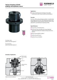
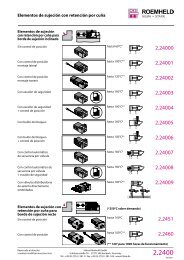
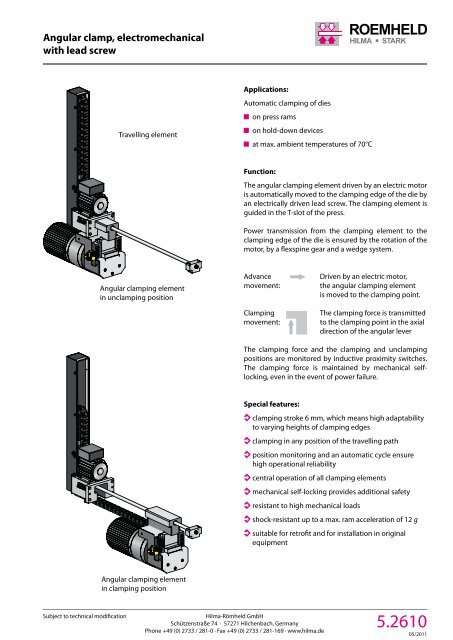
<strong>Angular</strong> <strong>clamp</strong>, <strong>electromechanical</strong><strong>with</strong> <strong>lead</strong> screwTravelling elementApplications:Automatic <strong>clamp</strong>ing of dieson press ramson hold-down devicesat max. ambient temperatures of 70°CFunction:The angular <strong>clamp</strong>ing element driven by an electric motoris automatically moved to the <strong>clamp</strong>ing edge of the die byan electrically driven <strong>lead</strong> screw. The <strong>clamp</strong>ing element isguided in the T-slot of the press.Power transmission from the <strong>clamp</strong>ing element to the<strong>clamp</strong>ing edge of the die is ensured by the rotation of themotor, by a flexspine gear and a wedge system.<strong>Angular</strong> <strong>clamp</strong>ing elementin un<strong>clamp</strong>ing positionAdvancemovement:Clampingmovement:Driven by an electric motor,the angular <strong>clamp</strong>ing elementis moved to the <strong>clamp</strong>ing point.The <strong>clamp</strong>ing force is transmittedto the <strong>clamp</strong>ing point in the axialdirection of the angular leverThe <strong>clamp</strong>ing force and the <strong>clamp</strong>ing and un<strong>clamp</strong>ingpositions are monitored by inductive proximity switches.The <strong>clamp</strong>ing force is maintained by mechanical selflocking,even in the event of power failure.Special features:<strong>clamp</strong>ing stroke 6 mm, which means high adaptabilityto varying heights of <strong>clamp</strong>ing edges<strong>clamp</strong>ing in any position of the travelling pathposition monitoring and an automatic cycle ensurehigh operational reliabilitycentral operation of all <strong>clamp</strong>ing elementsmechanical self-locking provides additional safetyresistant to high mechanical loadsshock-resistant up to a max. ram acceleration of <strong>12</strong> gsuitable for retrofit and for installation in originalequipment<strong>Angular</strong> <strong>clamp</strong>ing elementin <strong>clamp</strong>ing positionSubject to technical modificationHilma-Römheld GmbHSchützenstraße 74 · 57271 Hilchenbach, GermanyPhone +49 (0) 2733 / 281-0 · Fax +49 (0) 2733 / 281-169 · www.hilma.de5.26<strong>10</strong>05/20<strong>11</strong>
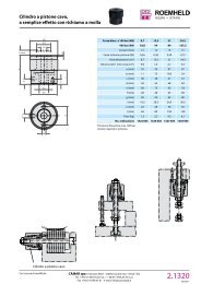
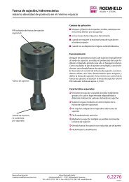
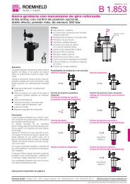
<strong>Angular</strong> <strong>clamp</strong>, <strong>electromechanical</strong><strong>with</strong> <strong>lead</strong> screwGeometry of the T-slot Travelling path TClamping dimensionTechnical dataTypeClamping force (kN)Max. static force (kN)Travelling speed (mm/s)Clamping speed (mm/s)Connected motor voltage (V/Hz)a (mm)b (mm)c (mm)d (mm)A (mm)B (mm)D (mm)H (mm)Total stroke hs (mm)Clamping stroke (mm)K (mm)M (mm)T (mm)W (mm)Y (mm)Clamping dimension to be quoted in the order8.2615.0<strong>10</strong>1 8.2616.0<strong>10</strong><strong>11</strong>20 160300 30064,0 64,01,0 1,0400/50 400/5048 4880 8048 4884 84160 160409 409160 160185 1856 62 2<strong>12</strong>3 <strong>12</strong>331 31<strong>10</strong>00 <strong>10</strong>00208 208870 870Other T-slots, <strong>clamp</strong>ing dimensions,<strong>clamp</strong>ing forces and motor voltagesare available on requestTerminal connections DriveParkingpositionDie positionUn<strong>clamp</strong>ingpositionClampingrangeClamping forcemonitoring5.26<strong>10</strong>05/20<strong>11</strong>Hilma-Römheld GmbHSchützenstraße 74 · 57271 Hilchenbach, GermanyPhone +49 (0) 2733 / 281-0 · Fax +49 (0) 2733 / 281-169 · www.hilma.deSubject to technical modification