
Create successful ePaper yourself
Turn your PDF publications into a flip-book with our unique Google optimized e-Paper software.
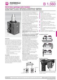
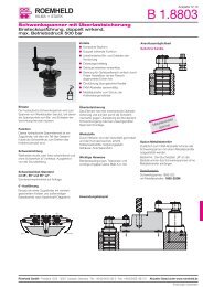
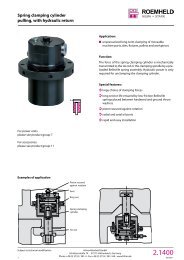
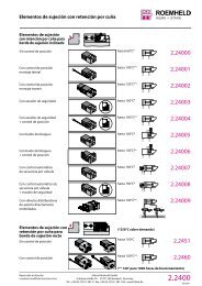
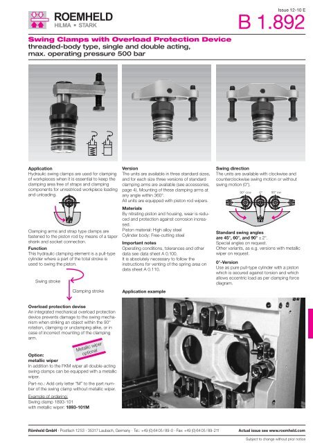
Swing Clamps with Overload Protection Devicethreaded-body type, single and double acting,max. operating pressure 500 barIssue 12-10 EB <strong>1.892</strong>ApplicationHydraulic swing clamps are used for clampingof workpieces when it is essential to keep theclamping area free of straps and clampingcomponents for unrestriced workpiece loadingand unloading.Clamping arms and strap type clamps arefastened to the piston rod by means of a tapershank and socket connection.FunctionThis hydraulic clamping element is a pull-typecylinder where a part of the total stroke isused to swing the piston.Swing Schwenkhub strokeClamping strokeSpannhubOverload protection deviseAn integrated mechanical overload protectiondevice prevents damage to the swing mechanismwhen striking an object within the 90°rotation, clamping or unclamping alike, or incase of incorrect mounting of the clampingarm.Metallic wiperoptionalOption:metallic wiperIn addition to the FKM wiper all double-actingswing clamps can be equipped with a metallicwiper.Part-no.: Add only letter “M” to the part numberof the swing clamp without metallic wiper.Example of ordering:Swing clamp 1893-101with metallic wiper: 1893-101MVersionThe units are available in three standard sizes,and for each size three versions of standardclamping arms are available (see accessories,page 4). Mounting of these clamping arms atany angle within 360°.All units are equipped with piston rod wipers.MaterialsBy nitrating piston and housing, wear is reducedand protection against corrosion increased.Piston material: High alloy steelCylinder body: Free-cutting steelImportant notesOperating conditions, tolerances and otherdata see data sheet A 0.100.It is absolutely necessary to follow theinstructions for venting of the spring area ondata sheet A 0.110.Application exampleSwing directionThe units are available with clockwise andcounterclockwise swing motion or withoutswing motion (0°).90° links ccw 0° 90° 90° rechts cwStandard swing anglesare 45°, 60°, and 90° ± 2°.Special angles on request.Other variants, as e.g. versions with metallicwiper on request.0°-VersionUse as pure pull-type cylinder with a pistonwhich is secured against torsion and whichallows eccentric load as per clamping forcediagram.Römheld GmbH · Postfach 1253 · 35317 Laubach, Germany · Tel.: +49 (0) 64 05 / 89-0 · Fax: +49 (0) 64 05 / 89-211Actual issue see www.roemheld.comSubject to change without prior notice
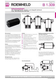
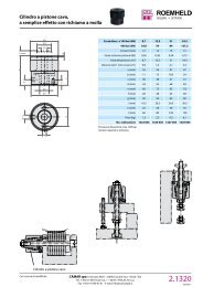
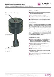
DimensionsTechnical DataAccessorysee page 4vwyCone 1:10ClampingUnclampingSintered metal airfilter for singleactingversionsManifold mounting hole„Z”rrStrokeOption:metallic wiperProlonged coveronly at version1883-1X2, 2X2q max.RadiusSpigoli edgesbavatinccwcwOil volume / stroke [cm 3 ] 3.2 10.0 27.7Oil volume / return stroke [cm 3 ] 8.8 27.7 74.8Total stroke [mm] 18 22 24Swing stroke [mm] 7 8 9Clamping stroke [mm] 11 14 15Operating pressure to swing min. [bar] 30 30 30Max. oil flow rate [cm 3 /s] 3.2 10.0 27.7c [mm] 52 64 100Ø d [mm] 20 32 50Ø e [mm] 23.5 33.5 55.5f [mm] 30 40 68g [mm] M 18x1.5 M 28x1.5 M 45x1.5h [mm] 112 152 182Ø i f7 [mm] 42 55 85Ø k H7 [mm] 42 55 85l [mm] - - 80m [mm] 91-1 124-1 142-1 (145-1)◊n [mm] 24 29 41o [mm] 53 66 96Ø p/deep [mm] - - 8/9Ø q max. [mm] 5 5 6r [mm] M 45x1.5 M 60x1.5 M 90x2s [mm] 41 46,5 64t [mm] 9 10 12Ø u [mm] 44 57 87v [mm] 37 41,5 59w [mm] 20 24 36x [mm] 70 99 116y [mm] 10.5 12.5 20.5z [mm] 8 10 10SW [mm] 46 55 95z zR max. 10m20°20°Ø kØ uq max.sClampingUnclamping or ventconnection forsingle-actingversionPart-no., single actingSwing direction cw 1883-102 1885-102 1887-102Swing direction ccw 1883-202 1885-202 1887-202Part-no., double actingClockwise rotation 1893-101 1895-101 1897-101Counterclockwise rotation 1893-201 1895-201 1897-201Detail „Z”r + 0,560°Seal kit for external seals 0131-524 0131-526 0131-528R13,5315° Radius SpigoloedgearrotondatoOther swing anglesSwing anglePart-no.90° 18XX-X0X60° 18XX-X2X45° 18XX-X3X0° 18XX-14X◊ (145-1) for clamping arm 0354-004* See page 3:Max. oil flow rateOption metallic wiperfor double-acting swing clampspartn-no.: 189X-XXXM2 Actual issue see www.roemheld.com Römheld GmbHB <strong>1.892</strong> / 12-10 ESubject to change without prior notice
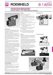
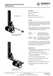
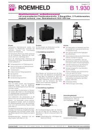
Technical DataEffective clamping force F Sp as function of operating pressure pEffective clamping force FSp [kN]1098765432Size 1Single acting (1883-XXX)Max. clamping arm length e [mm]100 66 50 40 33 28,5 251FSp00 100 200 300 400 500eFSpFSpFSpEffective clamping force FSp [kN]201816141210864Size 2Single acting (1885-XXX)Max. clamping arm length e [mm]150 100 75 60 50 43 37,5 33,5Example 2Example 1FSp2 FSp FSp00 100 200 300 400 500eFSpEffective clamping force FSp [kN]5040302010Size 3Single acting (1887-XXX)Max. clamping arm length e [mm]240 160 120 96 80 68 60 53 48FSp00 100 200 300 400 500eFSpFSpFSpOperating pressure [bar]Operating pressure [bar]Operating pressure [bar]Effective clamping force FSp [kN]1098765432Double acting (1893-XXX)Max. clamping arm length e [mm]100 66 50 40 33 28,5 251FSp00 100 200 300 400 500Operating pressure [bar]eFSpFSpFSpEffective clamping force FSp [kN]201816141210864Double acting (1895-XXX)Max. clamping arm length e [mm]150 100 75 60 50 43 37,5 33,5FSp2 FSp FSp00 100 200 300 400 500Operating pressure [bar]eFSpEffective clamping force FSp [kN]5040302010Double acting (1897-XXX)Max. clamping arm length e [mm]240 160 120 96 80 68 60 53 48FSp00 100 200 300 400 500Operating pressure [bar]eFSpFSpFSpNote:The clamping force of single-acting swingclamps is reduced by the opposite-directedspring return force.For this reason the clamping force is slightlylower than that of double-acting swing clamps.Example 1: 1885-102 single acting. Anoperating pressure p of 200 bar in connectionwith standard clamping arm 0354-003 of max.arm length L = 75 mm results in an effectiveclamping force F Sp of 5.8 kN.Example 2: 1885-102 single acting. For adesired effective clamping force F Sp of 8 kNand use of a swing clamp 1885-102 with astandard clamping strap 0354-002 anoperating pressure p of 345 bar is required.Important notes1. Danger of injuryHydraulic clamping elements can generateconsiderable forces.Due to the 90° swing motion, the exactclamping and unclamping position cannot bedetermined in advance. Considerable injuriescan be caused to fingers in the effective areaof the clamping arm.Remedy: protection device with electricallocking.2. Maximum oil flow rateIn case of the maximum oil flow rate as perchart the shortest possible clamping time is1 second. If the flow rate of the pump dividedby the number of swing clamps is higher thanthe indicated value in the chart, the flow ratehas to be throttled to avoid snapping out ofthe overload protection device. In the casethat the mounting position is not verticaland/or heavy clamping arms are used, theflow rate has to be further reduced, if required.Throttling has to be made in the oil supply lineto the swing clamp to rule out a possible pressureintensification. Use only flow controlcheck valves which allow oil return from theswing clamps without any impediments, ase.g. the flow-control swivel banjo coupling9208-129 on page C 2.9501.During unclamping the maximum oil flow ratecan be 2.8 higher than the indicated value inthe chart, because the piston area is correspondinglybigger.3. Unimpeded swing motionThe swing motion must not be impeded andthe clamping arm may only contact the workpieceafter completion of the swing stroke.4. Clamping arm assemblyIn case of this threaded-body type the clampingarm can only be fixed, after firm screwingin of the housing, since the final positioncannot be determined in advance.When tightening and untightening the fixingscrew , the clamping arm has to be backedup to avoid the introduction of moments to thepiston rod.5. Adjustment of contact boltThe contact bolt may only contact the workpieceafter completion of the swing motion.When tightening and untightening the fixingscrew, the clamping arm has to be backed up(see 4.).6. Special clamping armsWhen using special clamping arms with otherlengths, the corresponding operating pressuresas shown in the clamping force diagrammust not be exceeded. If longer clampingarms will be used, not only the operating pressurebut also the flow rate have to be reduced(see 2.).7. Venting of spring areaThe spring area of single-acting swing clampshas to be vented to avoid problems in functioning.A sintered metal air filter avoids penetrationof contaminations. If there is a possibilitythat cutting lubricants and coolants penetratethrough the sintered metal air filter into thecylinder’s interior, a vent hose has to beconnected and be placed in a protectedposition (see data sheet A 0.110).8. BleedingAir in the oil prolongs the clamping time considerablyand leads to function problems. Thereforebleeding has to be effected during startup. The threaded-body swing clamp has nopossibility for bleeding at the element itself.Remedy: plug the oil channels in the fixturebody at the end. If required, loosen the plugscarefully and pump at low oil pressure untilbubblefree oil comes out. Retighten the plugs.Römheld GmbH Actual issue see www.roemheld.com 3B <strong>1.892</strong> / 12-10 ESubject to change without prior notice
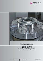
Dimensionsfor specialclampingarmsbØ cØ dgaClamping armassembly,complete,max. 200 barMaterial: 42CrMo4d hgeafbcwithout withthread threadSwing clamp a b c d e f g h max. h min. Weight [kg] Part-no.18X3-XXX 75 16 32 16 50 16 M10 64 6 0.2 0354-00118X5-XXX 115 23 48 22 75 25 M16 79 9 0.7 0354-00318X7-XXX 178 34 78 40 120 40 M20 98 12 2.55 0354-005Swing clamp a b c d f Weight [kg] Part-no.18X3-XXX 75 16 32 16 16 0.18 3921-01618X5-XXX 115 23 48 22 25 0.65 3921-01718X7-XXX 178 34 78 40 40 2.3 3921-018Clamping strapassembly,complete,with carrier,max. 500 bard h bgeefCone 1:10+ 0.10Swing clamp a b Øc Ød+ 0.05 e f g Øh f718X3-XXX 16 4 24 19.8 10 21 M 18x1.5 2018X5-XXX 23 5 34 31.8 12 28 M 28x1.5 3218X7-XXX 34 6 56 49.8 13 40 M 45x1.5 50Ø hClamping arm,max. 300 bariefdbhgAccessoriesSwing clamp a b c d e f g h i Weight [kg] Part-no.18X3-XXX 51.5 21 32 14 33.5 16 15.5 14.5 7 0.11 3548-23818X5-XXX 76 28 46 25 50 23 22.5 19 7 0.30 3548-23618X7-XXX 123 40 75 39 82.5 37.5 34 27 8 1.30 3548-302cMaterial: 42CrMo4akficSupportSwing clamp a b c d e f g h max. h min. i k Weight [kg] Part-no.18X3-XXX 122 30 1.5 44 60 45 M10 64 6 53 14.5 0.57 0354-00018X5-XXX 185 45 2 58.5 83 75 M16 79 9 87 21 1.58 0354-00218X7-XXX 223 59 2.5 98 100 90 M20 98 12 105 33 4.75 0354-004aMaterial: GGG-40Carrier for specialclamping strapb egfhdcSwing clamp a b c d e f g H7 h Weight [kg] Part-no.18X3-XXX 46 26 32 16 7.5 14.5 8 16 0.08 3542-09318X5-XXX 59 32 40 23 13 21 10 22 0.16 3542-09418X7-XXX 90 56 68 34 21 33 14 36 0.65 3542-096aMaterial: C 45Double clampingarm assembly,complete,with carrier,max. 500 bar±2°eegb f cSWPistonrod Ø dSwing clamp a b c Ød e f min. f max. g SW Weight [kg] Part-no.18X3-XXX 138 59 28.5 20 60 10 64 M 10 5 0.83 0354-13118X5-XXX 196 75 38 32 83 15 79 M 16 8 2.11 0354-13218X7-XXX 236 105 56 50 100 19 98 M 20 8 5.24 0354-134aMaterial: GGG-40Carrier, completewith threadedbolt and springclampingelementsbcØ fegPistonrod Ø daSWSwing clamp a±0,1 b c Ød e Øf g6 g* SW Part-no.18X3-XXX 43 16 7.5 20 9 10 21.5 5 0354-14118X5-XXX 55 23 11 32 11 16 29 8 0354-14218X7-XXX 77 34 17 50 15 20 41 8 0354-144* Stop surface for spring elementsMaterial: C 45aSpring elements4 Actual issue see www.roemheld.com Römheld GmbHB <strong>1.892</strong> / 12-10 ESubject to change without prior notice