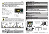
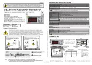
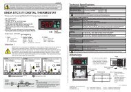
TERMSPROGRAMMABLE INDICATORENDASETEI1411) Measurement value, measurement unit, the minimum or the maximum measured values aredisplayed in the run mode.Parameter name, parameter value or a user defined unit is displayed in the programming mode.2) Increment or parameter selection key in the programming mode.Used for displaying measurement unit or the max. measured value in the run mode.3) Decrement or parameter selection key in the programming mode.Used for making the minimum and the maximum measured values equal in the run mode.4) Used for selecting run and programming modes, adjusting parameters, displayingmeasurement unit or making the minimum and the maximum measured values equal.( 1 ) Digital displayCharacter height( 2 ),( 3 ),( 4 ),( 5 ) Keypad4 digits 7 segment yellow LED display12.5mmMicro switchDIMENSIONS35mm77mmPROGRAMMABLE INDICATORENDASETEI141For removing mounting clamps:- Push up the flush-mountingclamp in direction 1 asshown in the figure above.- Then, pull out the clamp indirection 2.Flush mountingclamp2Panel71mmPanel5mmRubberpacking11 2 3 4 5 6 7 8 9 10 11 12GND+INPUTSN: XXXXXXXXX2 30 V AC +10%-20%50/60Hz 7VAENDA INDUSTRIAL ELECTRONICSEI141-230VACPROGRAMMABLE INDICATORFlush mountingclampPanel cut-out71mmNote :1) Panel thickness should be maximum 7 mm.2) If there is no 60mm free space at the backside of the device, it would be difficult toremove it from the panel.29mmCONNECTION DIAGRAMENDA EI141 is intended for installation in control panels. Make sure that the device is used only for intended purpose. The shielding must begrounded on the instrument side. During an installation, all of the cables that are connected to the device must be free of energy. The devicemust be protected against inadmissible humidity, vibrations, severe soiling and make sure that the operation temperature is not exceeded. Allinput and output lines that are not connected to the supply network must be laid out as shielded and twisted cables. These cables should not beclose to the power cables or components. The installation and electrical connections must be carried on by a qualified staff and must beaccording to the relevant locally applicable regulations.ENDA INDUSTRIAL ELECTRONICSEI141 PROGRAMMABLE INDICATOR230V AC +10% -20%50/60Hz 7VASN: XXXXXXXXXGND+1 2 3 4 5 6 7 8 9 10 11 12INPUTENDA INDUSTRIAL ELECTRONICSEI141-24AC PROGRAMMABLE INDICATOR24V AC +10% -20%50/60Hz 7VASN: XXXXXXXXX1 2 3 4 5 6 7 8 9 10 11 12GND+INPUTENDA INDUSTRIAL ELECTRONICSEI141-24DC PROGRAMMABLE INDICATOR24V DC ± 10%7VA+-SN: XXXXXXXXX1 2 3 4 5 6 7 8 9 10 11 12GND+INPUTNOTE :SUPPLY :184-253V AC50/60Hz 7VA12LineNeutralFuseF 100 mA250V ACFuse shouldbe connectedSwitch230V ACSupplyCable size: 1,5mm²Holding screw0.4-0.5NmEquipment is protected throughoutby DOUBLE INSULATION.Note :1) Mains supply cords shall meet the requirements of IEC 60227 or IEC 60245.2) In accordance with the safety regulations, the power supply switch shall bring the identification of the relevant instrument and it should beeasily accessible by the operator.2./3 EI141-E
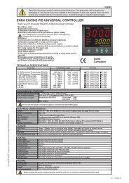
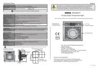
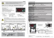
..1000Measurementvalue&Bar.If first and then keys arepressed together , measurementunit appears. SeeparameterFor programming.UnitRunning ModeSETPressing this key the minumummeasured value up to that timeappears.The minumummeasured value The maximummeasured valueMeasurement unit 870 1453Pressing this key the maximummeasured value up to that timeappearsRes.If first and then keys arepressed together, the maximum andthe minumum measurement valuesbecome equal to the measured value atthat time and the message res.appears on display.SET SETSETSETIf key is pressed and held for 5seconds programming mode is enteredSETProgramming ModeEntering from programming mode to run mode:If no key is pressed within 20 seconds during programming mode data is stored automatically and the runmode is entered. Alternatively the same function occurs by pressing key and holding for 5 secondsSETd.Cnf.U.opt. d.Cal. SeCU.i.typ.dsp.C.rateHoldUniti.typ. = Input type.Input type can be selected as 0-20mA,4-20mA, 0-1V or 0-10V.See NOTE 1 for programming.dSP.C. = Display configuration.Selectable as PrcS. or Pr.Un. . If PrcS. isselected, process value appears. If Pr.Un.is selected, process value and thenmeasurement unit are displayed 4 and 2seconds successively.See NOTE 1 for programming.RAtE = Sampling rate.Measurement is performed at each 200ms.However,for FASt rate, each measurement is displayed.for SLo.1 rate, the average of 4 successivemeasurements is displayed.for SLo.2 rate, the average of 8 successivemeasurements is displayed.for SLo.3 rate, the average of 16 successivemeasurements is displayed.See NOTE 1 for programming.Hold = Display holding parameter.Selecting NonE , this parameter becomesinactive.Selecting Lo. , always the minimummeasured value is displayed.Selecting Hi. , always the maximumUnit = Measurement unit.A constant, a message etc. to be displayedcan be entered. If a decimal point is desired,it should be included before entering thecharacter.NoCal.t.d.pnt.l.sCl.H.sCl.CAL.t.=U.ýnP.Evetl.inp.H.inp.CAL.t. = Calibration type.Selectable as S.inP or U.inP .If S.inp is selected, input type is one thefour standard input types. If U.inP isselected, input types can be modified.See NOTE 1 for modification.S.Cod.a.CAL.1.CA.10.CA.S.Cod.d.C.sc.Uo.sc.D.Ca.s.SETFor including decimal point first, then,keys are pressed and held together. Andthen, by using key decimal point can bed.Pnt. = Decimal point.Decimal point can be adjusted between1 . and 3. digits or without dp.See NOTE 1 for programming.L.SCL. = Lower limit for the scale.It can be adjusted between -1999 and( H.SCL. -100).See NOTE 1 for programming.H.SCL. = Upper limit for scale.It can be adjusted between ( L.SCL. +100)and 4000.See NOTE 1 for programming.At this state, the reference voltage orcurrent that corresponds to L.SCL. Parameteris applied to the input.To initialize calibration, first thenSETkeys are pressed together and held until ‘ CAL 'message appears. See NOTE 2.At this state, the reference voltage orcurrent that corresponds to H.SCL.parameter is applied to the input.SETSETSETSETNOTE 1Parameter adjustment methodTo initialize calibration, first thenkeys are pressed together and held until‘ CAL ' message appears. See NOTE 2.s.Cod. = Access code for calibration menu.This parameter should be 222 .See NOTE 1 for programming.A.CAL. = Current calibration.At this state, 20.000 mA current is applied to theinput of the device.For initializing calibration, first thenkeys are pressed together and held until ‘ CAL 'message appears. See NOTE 3.1.CA. = 1V input calibration.At this state, 1.0000V is applied to the input ofthe device.To initialize calibration, first thenkeys are pressed together and held until ‘ CAL 'message appears. See NOTE 3.10.CA. = 10V input calibration.At this state, 10.000V is applied to the input ofthe device.To initialize calibration, first thenkeys are pressed together and held until ‘ CAL 'message appears. See NOTE 3.NOTE 2 NOTE 3CAL. CAL.C.end s.err. C.endS.err.The message on the left flashes approximately 5seconds and calibration is completed.No NoIf calibration is error free, the messageYes C.End appears for 1 seconds . However, Yesif it is wrong, the message S.Err.appears for 1 seconds and the programis shifted to the next step.CAL okey?CAL okey?ERROR MESSAGESs.Cod. = Access code for safety menu.This parameter should be 333.See NOTE 1 for programming.d.C.Sc. = ConF. menu protection levelparameter.= No menu is seen.nonEP. noP.yES.= Menu is seen but can not be programmed.= Menu is seen and programming is possible.See NOTE 1 for programming.Uo.Sc. =U.oPt. menu protection levelparameter.nonE = No menu is seen.P. no = Menu is seen but can not be programmed.P.yES. = Menu is seen and programming is possible.See NOTE 1 for programming.d.Ca.S. =d.CAL. menu protection levelparameter.nonE = No menu is seen.P. no = Menu is seen but can not be programmed.P.yES. = Menu is seen and programming is possible.See NOTE 1 for programming.The message on the left flashes approximately 5seconds and calibration is completed.C.err.If calibration is error free, the messageC.End appears for 1 seconds . However,if it is wrong, the message C.Err.appears for 1 seconds and the programis shifted to the next step.SETFor adjusting a selected parameter first press and hold key. Then, by using keys adjustmentcan be made.If increment key is pressed and held 0.6 seconds, the value of the selected parameter changes rapidly.IfIf the difference between the reference voltages or currents applied for the calibration of H.inP. and L.inP. is lower than onehalf of the full scale, this error message appears on the display.For example: Assume that the selected input type is 0-1V. In this case, if the difference between the reference voltagesapplied for calibration of H.inP. and L.inP. is lower than 0.5V, this error message appears.C.err.If the reference voltage or current applied to the input for calibration is too high or too low, this error message appears.3 ./3 EI141 -E