InnoDisk EDC4000 Embedded Disk Card 4000 Datasheet
InnoDisk EDC4000 Embedded Disk Card 4000 Datasheet
InnoDisk EDC4000 Embedded Disk Card 4000 Datasheet

You also want an ePaper? Increase the reach of your titles
YUMPU automatically turns print PDFs into web optimized ePapers that Google loves.
<strong>Embedded</strong> <strong>Disk</strong> <strong>Card</strong> <strong>4000</strong> <strong>Datasheet</strong><strong>Inno<strong>Disk</strong></strong> <strong>EDC<strong>4000</strong></strong><strong>Embedded</strong> <strong>Disk</strong> <strong>Card</strong> <strong>4000</strong><strong>Datasheet</strong>Rev 1.71 Rev. 1.7 <strong>Datasheet</strong>, Jul. 2009
<strong>Embedded</strong> <strong>Disk</strong> <strong>Card</strong> <strong>4000</strong> <strong>Datasheet</strong>6.1 CHECK POWER MODE – 98H OR E5H..............................................................................................................356.2 EXECUTE DEVICE DIAGNOSTIC – 90H .............................................................................................................356.3 ERASE SECTOR – C0H...................................................................................................................................366.4 FORMAT TRACK – 50H ...................................................................................................................................366.5 IDENTIFY DEVICE – ECH ................................................................................................................................376.6 IDLE -97H OR E3H.........................................................................................................................................446.7 IDLE IMMEDIATE - 95H OR E1H .......................................................................................................................446.8 INITIALIZE DEVICE PARAMETERS - 91H ............................................................................................................456.10 READ BUFFER - E4H....................................................................................................................................456.11 READ LONG SECTOR - 22H OR 23H..............................................................................................................466.12 READ SECTOR(S) - 20H OR 21H...................................................................................................................466.13 READ VERIFY SECTOR(S) - 40H OR 41H .......................................................................................................476.14 RECALIBRATE - 1XH.....................................................................................................................................476.15 SEEK - 7XH .................................................................................................................................................486.16 SET FEATURES – EFH..................................................................................................................................486.17 SET SLEEP MODE - 99H OR E6H..................................................................................................................496.18 STANDBY - 96H OR E2H...............................................................................................................................506.19 STANDBY IMMEDIATE - 94H OR E0H..............................................................................................................506.20 WRITE BUFFER - E8H ..................................................................................................................................506.21 WRITE SECTOR(S) - 30H OR 31H .................................................................................................................517. DEVICE PARAMETERS...........................................................................................................................523 Rev. 1.7 <strong>Datasheet</strong>, Jul. 2009
<strong>Embedded</strong> <strong>Disk</strong> <strong>Card</strong> <strong>4000</strong> <strong>Datasheet</strong>REVISION HISTORYRevision Description Date1.0 Release first version December 20071.1 Modify storage temperature April 20081.2 Add product model June 20081.3 Modify operating temperature Aug. 20081.4 Add ATA command information and features Oct. 20081.5 Modify Mechanical Dimensions and typo errors Nov. 20081.6 Modify Mechanical Dimensions and Access mode errors Feb. 20091.7 Delete 00h and C6h command support Jul. 20094 Rev. 1.7 <strong>Datasheet</strong>, Jul. 2009
<strong>Embedded</strong> <strong>Disk</strong> <strong>Card</strong> <strong>4000</strong> <strong>Datasheet</strong>List of TablesTABLE 1: <strong>EDC<strong>4000</strong></strong> PIN ASSIGNMENT....................................................................................................................7TABLE 2: <strong>EDC<strong>4000</strong></strong> PIN DESCRIPTION ...................................................................................................................8TABLE 3: SHOCK/VIBRATION TESTING FOR <strong>EDC<strong>4000</strong></strong>...........................................................................................14TABLE 4: <strong>EDC<strong>4000</strong></strong> MTBF..................................................................................................................................14TABLE 5: READ/WRITE TIMING SPECIFICATIONS, PIO MODE 0-4............................................................................29TABLE 6: READ/WRITE TIMING SPECIFICATIONS, MULTIWORD DMA MODE 0-2 ......................................................30TABLE 7: TIMING DIAGRAM, ULTRA DMA MODE 0-4..............................................................................................32TABLE 8: IDE COMMANDS....................................................................................................................................34TABLE 9: CHECK POWER MODE COMMAND INFORMATION.......................................................................................35TABLE 10: EXECUTE DEVICE DIAGNOSTIC COMMAND INFORMATION ........................................................................35TABLE 11: EXECUTE DEVICE DIAGNOSTIC CODES...................................................................................................36TABLE 12: ERASE SECTOR COMMAND INFORMATION..............................................................................................36TABLE 13: FORMAT TRACK COMMAND INFORMATION .............................................................................................36TABLE 14: IDENTIFY DEVICE COMMAND INFORMATION ............................................................................................37TABLE 15: IDENTIFY DEVICE COMMAND FOR DATA RETURNED INFORMATION............................................................37TABLE 16: IDLE COMMAND INFORMATION ..............................................................................................................44TABLE 17: IDLE IMMEDIATE COMMAND INFORMATION .............................................................................................45TABLE 18: INITIALIZE DEVICE PARAMETERS COMMAND INFORMATION......................................................................45TABLE 19: READ BUFFER COMMAND INFORMATION................................................................................................45TABLE 20: READ LONG SECTOR COMMAND INFORMATION ......................................................................................46TABLE 21: READ SECTOR COMMAND INFORMATION ...............................................................................................46TABLE 22: READ VERIFY SECTOR COMMAND INFORMATION ....................................................................................47TABLE 23: RECALIBRATE COMMAND INFORMATION................................................................................................47TABLE 24: IDENTIFIER AND SECURITY LEVEL BIT INTERACTION..............................................................................48TABLE 25: SEEK COMMAND INFORMATION.............................................................................................................48TABLE 26: SET FEATURES COMMAND INFORMATION...............................................................................................49TABLE 27: FEATURE SUPPORTED .........................................................................................................................49TABLE 28: SET SLEEP MODE COMMAND INFORMATION ...........................................................................................49TABLE 29: STANDBY COMMAND INFORMATION.......................................................................................................50TABLE 30: STANDBY IMMEDIATE COMMAND INFORMATION......................................................................................50TABLE 31: WRITE BUFFER COMMAND INFORMATION ..............................................................................................50TABLE 32: WRITE SECTOR COMMAND INFORMATION ..............................................................................................51TABLE 33: DEVICE PARAMETERS ..........................................................................................................................525 Rev. 1.7 <strong>Datasheet</strong>, Jul. 2009
<strong>Embedded</strong> <strong>Disk</strong> <strong>Card</strong> <strong>4000</strong> <strong>Datasheet</strong>List of FiguresFIGURE 1: <strong>EDC<strong>4000</strong></strong> BLOCK DIAGRAM ................................................................................................................10FIGURE 2: 40-PIN CONNECTOR LAYOUT (FEMALE) ................................................................................................ 11FIGURE 3: 44-PIN CONNECTOR LAYOUT (FEMALE) ................................................................................................ 11FIGURE 4: 40-PIN CONNECT LAYOUT (MALE) ........................................................................................................ 11FIGURE 5: 44-PIN CONNECTOR LAYOUT (MALE).................................................................................................... 11FIGURE 6: MECHANICAL DIMENSION OF <strong>EDC<strong>4000</strong></strong> 40-PIN.....................................................................................15FIGURE 7: MECHANICAL DIMENSION OF <strong>EDC<strong>4000</strong></strong> 40-PIN (HORIZONTAL FEMALE TYPE A).....................................16FIGURE 8: MECHANICAL DIMENSION OF <strong>EDC<strong>4000</strong></strong> 40-PIN(HORIZONTAL FEMALE TYPE B)......................................17FIGURE 9: MECHANICAL DIMENSION OF <strong>EDC<strong>4000</strong></strong> 40-PIN(HORIZONTAL MALE TYPE C) .........................................18FIGURE 10: MECHANICAL DIMENSION OF <strong>EDC<strong>4000</strong></strong> 40-PIN(HORIZONTAL MALE TYPE D) .......................................19FIGURE 11: MECHANICAL DIMENSION OF <strong>EDC<strong>4000</strong></strong> 40-PIN(HORIZONTAL FEMALE/MALE TYPE E) ..........................20FIGURE 12: MECHANICAL DIMENSION OF <strong>EDC<strong>4000</strong></strong> 40-PIN(HORIZONTAL MALE/FEMALE TYPE F) ..........................21FIGURE 13: MECHANICAL DIMENSION OF <strong>EDC<strong>4000</strong></strong> 44-PIN (VERTICAL VERSION) ..................................................22FIGURE 14: MECHANICAL DIMENSION OF <strong>EDC<strong>4000</strong></strong> 44-PIN (HORIZONTAL FEMALE TYPE A)...................................23FIGURE 15: MECHANICAL DIMENSION OF <strong>EDC<strong>4000</strong></strong> 44-PIN (HORIZONTAL FEMALE TYPE B)...................................24FIGURE 16: MECHANICAL DIMENSION OF <strong>EDC<strong>4000</strong></strong> 44-PIN (HORIZONTAL MALE TYPE C) ......................................25FIGURE 17: MECHANICAL DIMENSION OF <strong>EDC<strong>4000</strong></strong> 44-PIN (HORIZONTAL MALE TYPE D) ......................................26FIGURE 18: MECHANICAL DIMENSION OF <strong>EDC<strong>4000</strong></strong> 44-PIN (HORIZONTAL FEMALE/MALE TYPE E) .........................27FIGURE 19: MECHANICAL DIMENSION OF <strong>EDC<strong>4000</strong></strong> 44-PIN (HORIZONTAL MALE/FEMALE TYPE F) .........................28FIGURE 20: READ/WRITE TIMING DIAGRAM, PIO MODE ........................................................................................29FIGURE 21: READ/WRITE TIMING DIAGRAM, MULTIWORD DMA MODE...................................................................30FIGURE 22: ULTRA DMA MODE DATA-IN BURST INITIATION TIMING DIAGRAM........................................................31FIGURE 23: ULTRA DMA MODE DATA-OUT BURST INITIATION TIMING DIAGRAM ....................................................31FIGURE 24: SUSTAINED ULTRA DMA MODE DATA-IN BURST TIMING DIAGRAM.......................................................32FIGURE 25: SUSTAINED ULTRA DMA MODE DATA-OUT BURST TIMING DIAGRAM....................................................326 Rev. 1.7 <strong>Datasheet</strong>, Jul. 2009
<strong>Embedded</strong> <strong>Disk</strong> <strong>Card</strong> <strong>4000</strong> <strong>Datasheet</strong>1. Product Overview1.1 Introduction to <strong>Embedded</strong> <strong>Disk</strong> <strong>Card</strong> <strong>4000</strong><strong>Embedded</strong> <strong>Disk</strong> <strong>Card</strong> <strong>4000</strong> (<strong>EDC<strong>4000</strong></strong>) products provide high capacity solid-state flash memory thatelectrically complies with the Personal Computer Memory <strong>Card</strong> International Association ATA standard.<strong>Inno<strong>Disk</strong></strong> <strong>Embedded</strong> <strong>Disk</strong> <strong>Card</strong> <strong>4000</strong> (<strong>EDC<strong>4000</strong></strong>) is embedded solid-state data storage systems for industrialwork place. <strong>Embedded</strong> <strong>Disk</strong> <strong>Card</strong> <strong>4000</strong> (<strong>EDC<strong>4000</strong></strong>) features an extremely light weight, reliable, low-profile formfactor.<strong>Embedded</strong> <strong>Disk</strong> <strong>Card</strong> <strong>4000</strong> (<strong>EDC<strong>4000</strong></strong>) supports advanced PIO (0-4), Multi Word DMA (0-2), Ultra DMA (0-4)transfer modes, multi-sector transfers, and LBA addressing.1.2 Product Models<strong>Embedded</strong> <strong>Disk</strong> <strong>Card</strong> <strong>4000</strong> (<strong>EDC<strong>4000</strong></strong>) is available in capacities ranging from 32MB to 8GB, making theupgrade path simple and fast. Available in 40-pin and 44-pin horizontal connector packages, <strong>EDC<strong>4000</strong></strong> fits intoany platform with an IDE connector.1.3 FeaturesThe Industrial ATA products provide the following system features:‧ Capacities: 128MB to 8GB‧ Fully compatible with the IDE standard interface, ATA Standard‧ Access modes: True IDE Mode‧ ECC (Error Correction Code) function: 4 bits/ per 512 byte‧ +3.3V/+5V single power supply operation‧ Support Auto Stand-by and Sleep Mode.‧ Support transfer modes: PIO(0-4), Multiword DMA (0-2) and Ultra DMA(0-4)‧ MTBF 3,000,000 hours‧ R/W performance: Sustain Read: 40Mbytes/s. (MAX) Sustain Write: 20Mbytes/s (MAX)‧ Operating temperature range:- Standard Grade: 0°C ~ +70°C- Industrial Grade: -40°C ~ +85°C‧ Storage temperature range: -55°C ~ +95°C1.4 Pin Assignment<strong>EDC<strong>4000</strong></strong> uses a standard IDE pin-out. See Table 1 for <strong>EDC<strong>4000</strong></strong> pin assignments.Table 1: <strong>EDC<strong>4000</strong></strong> Pin AssignmentPin No. Name Function Pin No. Name Function1 HRESET Host Reset 2 GND Ground3 HDB[7] Host Data Bit 7 4 HDB[8] Host Data Bit 87 Rev. 1.7 <strong>Datasheet</strong>, Jul. 2009
<strong>Embedded</strong> <strong>Disk</strong> <strong>Card</strong> <strong>4000</strong> <strong>Datasheet</strong>5 HDB[6] Host Data Bit 6 6 HDB[9] Host Data Bit 97 HDB[5] Host Data Bit 5 8 HDB[10] Host Data Bit 109 HDB[4] Host Data Bit 4 10 HDB[11] Host Data Bit 1111 HDB[3] Host Data Bit 3 12 HDB[12] Host Data Bit 1213 HDB[2] Host Data Bit 2 14 HDB[13] Host Data Bit 1315 HDB[1] Host Data Bit 1 16 HDB[14] Host Data Bit 1417 HDB[0] Host Data Bit 0 18 HDB[15] Host Data Bit 1519 GND Ground 2040-pin VCC 1 Supply Voltage44pin KEY 1 Key-pin21 DMARQ DMA Request 22 GND GroundHIOW 3 Host I/O Write23STOP 4 Stop Ultra DMA 24 GND GroundburstHIOR 3Host I/O ReadHDMARDY 4 Ultra DMA ready2526 GND GroundHSTROBE 4 Ultra DMA datastrobeIORDY 3I/O Ready27DDMARDY 4DSTROBE 4Ultra DMA readyUltra DMA datastrobe28 CSELMaster/Slave Select(Switch used)29 DMACK DMA Acknowledge 30 GND Ground31 INTRQ Interrupt Request 32 IOCS16 CS I/O 16-Bit33 HAB[1] Host Address Bit 1 34 PDIAG Passed DiagnosticPin No. Name Function Pin No. Name Function35 HAB[0] Host Address Bit 0 36 HAB[2] Host Address Bit 237 CS0 Chip Select 0 38 CS1 Chip Select 139 DASP Drive Active 40 GND Ground41 2 VCC Supply Voltage 42 2 VCC Supply Voltage43 2 GND Ground 44 2 NC Not Connected1. In the 40-pin version, this pin is defined as VCC to reduce the need for an external power connector. Inthe 44-pin version, this pin is defined as KEY, according to the ATA standard.2. The 40-pin version does not contain pins 41-44.NC = These pins are not connected internally.3. Signal usage in PIO & Multiword DMA mode.4. Signal usage in Ultra DMA mode.1.5 Pin DescriptionTable 2 describes the pin descriptions for <strong>EDC<strong>4000</strong></strong>Table 2: <strong>EDC<strong>4000</strong></strong> Pin DescriptionPin Name Pin No. Description I/OHost side pinsHRESET- 1 Host reset signal, High: Reset. ICS0- 37 Chip select CS0 ICS1- 38 Chip select CS1 IINTRQ 31 Host interrupt signal. OHIOR- 325 I/O read strobe signal.IHDMARDY- 4 DMA ready during Ultra DMA data in burst8 Rev. 1.7 <strong>Datasheet</strong>, Jul. 2009
<strong>Embedded</strong> <strong>Disk</strong> <strong>Card</strong> <strong>4000</strong> <strong>Datasheet</strong>HSTROBE 4Data strobe during Ultra DMA data out burstHIOW- 3I/O write strobe signal.STOP 4 23Stop during Ultra DMA data burstsIIOCS16- 32 Asserted in 16-bit access. OIORDY 3I/O Ready SignalDDMARDY- 4 27 DMA ready during Ultra DMA data out burstODSTROBE 4 Data strobe during Ultra DMA data in burstHDB[15:0]18, 16, 14, 12,10, 8, 6, 4, 3, 5, 7, Host data busI/O9, 11, 13, 15, 17HAB[2:0] 33, 35, 36 Host Address bus I/OCSEL- 28Master/Slave select signal (cable select signal).Low: Device operates as a master, High: Device operates as aslave.ISwitch used.DASP- 39Used as an input port to check in the master mode to see if theslave is present or not, and as an output port to check in the I/Oslave mode to see if the slave for the master is present or not.PDIAG- 34Used as an input port to evaluate the result of slave diagnosisin the master mode, and as an output port to return the result of I/Odiagnosis to the master.DMARQ 21 DMA Request. ODMACK- 29 DMA Acknowledge. IPower and GroundVCC 20 1 , 41 2 , 42 2 Connect to VCC VCCGND2, 19, 22, 24, 26,30, 40, 43 2 Connect to GND. GNDOther pinsNC 44 2 Not used. Please do not connect. N/A1. In the 40-pin version, this pin is defined as VCC to reduce the need for an external power connector. Inthe 44-pin version, this pin is defined as KEY, according to the ATA standard.2. The 40-pin version does not contain pins 41-44.NC = These pins are not connected internally.3. Signal usage in PIO & Multiword DMA mode.4. Signal usage in Ultra DMA mode.9 Rev. 1.7 <strong>Datasheet</strong>, Jul. 2009
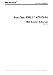
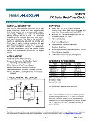
<strong>Embedded</strong> <strong>Disk</strong> <strong>Card</strong> <strong>4000</strong> <strong>Datasheet</strong>2. Theory of operation2.1 OverviewFigure 1 shows <strong>EDC<strong>4000</strong></strong> operation from the system level, including the major hardware blocks.Figure 1: <strong>EDC<strong>4000</strong></strong> Block Diagram<strong>EDC<strong>4000</strong></strong> integrates an IDE controller and flash devices. Communication with the host occurs through the hostinterface, using the standard ATA protocol. Communication with the flash device(s) occurs through the flashinterface.2.2 ControllerThe controller is equipped with 16KB of internal memory that is used for storing code and data. The internalmemory can also be used as an intermediate memory for storing data blocks during a wear-leveling procedure.An 8KB internal boot ROM includes basic routines for accessing the flash memories and for loading the maincode into the internal memory.2.3 Error Detection and CorrectionHighly sophisticated Error Correction Code algorithms are implemented. The ECC unit consists of the ParityUnit (parity-byte generation) and the Syndrome Unit (syndrome-byte computation). This unit implements aalgorithm that can correct 4 bits per 512 bytes in an ECC block. Code-byte generation during write operations,as well as error detection during read operation, is implemented on the fly without any speed penalties.2.4 Wear-LevelingFlash memory can be erased a limited number of times. This number is called the erase cycle limit or writeendurance limit and is defined by the flash array vendor. The erase cycle limit applies to each individual eraseblock in the flash device.<strong>EDC<strong>4000</strong></strong> uses a wear-leveling algorithm to ensure that consecutive writes of a specific sector are not writtenphysically to the same page in the flash. This spreads flash media usage evenly across all pages, therebymaximizing flash lifetime.10 Rev. 1.7 <strong>Datasheet</strong>, Jul. 2009
<strong>Embedded</strong> <strong>Disk</strong> <strong>Card</strong> <strong>4000</strong> <strong>Datasheet</strong>3. Installation Requirements3.1 <strong>EDC<strong>4000</strong></strong> Pin DirectionsFrom figure 2 to figure 5 are shown for the <strong>EDC<strong>4000</strong></strong> 40pin and 44pin pin directions.Figure 2: 40-pin Connector Layout (Female)Figure 3: 44-pin Connector Layout (Female)Figure 4: 40-pin Connect Layout (Male)Figure 5: 44-pin Connector Layout (Male)3.2 Electrical Connections for <strong>EDC<strong>4000</strong></strong><strong>EDC<strong>4000</strong></strong> can be connected to the host by placing it directly on the on-board socket. If a cable is used, itshould be no longer than 20 inches (457mm), and should be aligned as follows:‧ For 40-pin <strong>EDC<strong>4000</strong></strong>:Pin 1 of the cable must be aligned with pin 1 of the <strong>EDC<strong>4000</strong></strong> connector.Pin 40 of the cable must be aligned with pin 40 of the <strong>EDC<strong>4000</strong></strong> connector.‧ For 44-pin <strong>EDC<strong>4000</strong></strong>:Pin 1 of the cable must be aligned with pin 1 of the <strong>EDC<strong>4000</strong></strong> connector.Pin 44 of the cable must be aligned with pin 44 of the <strong>EDC<strong>4000</strong></strong> connector.The 40-pin <strong>EDC<strong>4000</strong></strong> version has a separate connector for the power supply, to which a power supply cablecan be connected. In addition, pin 20 can also be used for power supply connections. Please refer to the pin11 Rev. 1.7 <strong>Datasheet</strong>, Jul. 2009
<strong>Embedded</strong> <strong>Disk</strong> <strong>Card</strong> <strong>4000</strong> <strong>Datasheet</strong>description for further details.3.3 Installing <strong>EDC<strong>4000</strong></strong> in a Two-Drive Configuration (Master/Slave)If <strong>EDC<strong>4000</strong></strong> is being installed as an additional IDE drive using the same IDE I/O port, Switch S1 in “M” positionwill be the master, whereas in “S” position it becomes the slave.12 Rev. 1.7 <strong>Datasheet</strong>, Jul. 2009
<strong>Embedded</strong> <strong>Disk</strong> <strong>Card</strong> <strong>4000</strong> <strong>Datasheet</strong>4. Power Management<strong>EDC<strong>4000</strong></strong> supports the following two operation modes:Sleep Mode: Internal clock is halted (for <strong>EDC<strong>4000</strong></strong>, the standby mode defined in the ATA specification is thesame as this mode)Active Mode: Internal clock operates normally (for <strong>EDC<strong>4000</strong></strong>, the idle mode defined in the ATA specification isthe same as this mode)13 Rev. 1.7 <strong>Datasheet</strong>, Jul. 2009
<strong>Embedded</strong> <strong>Disk</strong> <strong>Card</strong> <strong>4000</strong> <strong>Datasheet</strong>5. Specifications5.1 CE, FCC and RoHS Compatibility CE and FCC Compatibility<strong>EDC<strong>4000</strong></strong> conforms to CE and FCC requirements. RoHS Compliance<strong>EDC<strong>4000</strong></strong> is fully compliant with RoHS directive.5.2 Environmental Specifications5.2.1 Temperature RangesOperating Temperature Range:- Standard Grade: 0°C to +70°C- Industrial Grade: -40°C to +85°CStorage Temperature Range: -55°C to +95°C5.2.2 HumidityRelative Humidity: 10-95%, non-condensing5.2.3 Shock and VibrationTable 3: Shock/Vibration Testing for <strong>EDC<strong>4000</strong></strong>Reliability Test Conditions Reference StandardsVibration 7 Hz to 2K Hz, 5G, 3 axes IEC 68-2-6Mechanical Shock Duration: 10ms, 50G, 3 axes IEC 68-2-275.2.4 Mean Time between Failures (MTBF)Table 4 summarizes the MTBF prediction results for various <strong>EDC<strong>4000</strong></strong> configurations. The analysis wasperformed using a RAM Commander failure rate prediction.‧ Failure Rate: The total number of failures within an item population, divided by the total number of lifeunits expended by that population, during a particular measurement interval under stated condition.‧ Mean Time between Failures (MTBF): A basic measure of reliability for repairable items: The meannumber of life units during which all parts of the item perform within their specified limits, during a particularmeasurement interval under stated conditions.Table 4: <strong>EDC<strong>4000</strong></strong> MTBFProduct Condition MTBF (Hours)14 Rev. 1.7 <strong>Datasheet</strong>, Jul. 2009
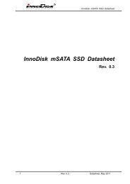
<strong>Embedded</strong> <strong>Disk</strong> <strong>Card</strong> <strong>4000</strong> <strong>Datasheet</strong>40-pin > 3,000,000Telcordia SR-332 GB, 25°C44-pin> 3,000,0005.3 Mechanical Dimensions5.3.1 Vertical type40pin Vertical (DE0H-XXXD3XXX)Mechanical Dimension: 60.2/6.4/27.8 mm±0.1(W/T/H)Figure 6: Mechanical Dimension of <strong>EDC<strong>4000</strong></strong> 40-pin5.3.2 Horizontal type15 Rev. 1.7 <strong>Datasheet</strong>, Jul. 2009
40pin Horizontal (DE0PA-XXXD3XXX)<strong>Embedded</strong> <strong>Disk</strong> <strong>Card</strong> <strong>4000</strong> <strong>Datasheet</strong>AFigure 7: Mechanical Dimension of <strong>EDC<strong>4000</strong></strong> 40-pin (Horizontal Female Type A)16 Rev. 1.7 <strong>Datasheet</strong>, Jul. 2009
<strong>Embedded</strong> <strong>Disk</strong> <strong>Card</strong> <strong>4000</strong> <strong>Datasheet</strong>40pin Horizontal (DE0PB-XXXD3XXX)BFigure 8: Mechanical Dimension of <strong>EDC<strong>4000</strong></strong> 40-pin(Horizontal Female Type B)17 Rev. 1.7 <strong>Datasheet</strong>, Jul. 2009
<strong>Embedded</strong> <strong>Disk</strong> <strong>Card</strong> <strong>4000</strong> <strong>Datasheet</strong>40pin Horizontal (DE0PC-XXXD3XXX)CFigure 9: Mechanical Dimension of <strong>EDC<strong>4000</strong></strong> 40-pin(Horizontal Male Type C)18 Rev. 1.7 <strong>Datasheet</strong>, Jul. 2009
<strong>Embedded</strong> <strong>Disk</strong> <strong>Card</strong> <strong>4000</strong> <strong>Datasheet</strong>40pin Horizontal (DE0PD-XXXD3XXX)DFigure 10: Mechanical Dimension of <strong>EDC<strong>4000</strong></strong> 40-pin(Horizontal Male Type D)19 Rev. 1.7 <strong>Datasheet</strong>, Jul. 2009
<strong>Embedded</strong> <strong>Disk</strong> <strong>Card</strong> <strong>4000</strong> <strong>Datasheet</strong>40pin Horizontal (DE0PE-XXXD3XXX)EFigure 11: Mechanical Dimension of <strong>EDC<strong>4000</strong></strong> 40-pin(Horizontal Female/Male Type E)20 Rev. 1.7 <strong>Datasheet</strong>, Jul. 2009
<strong>Embedded</strong> <strong>Disk</strong> <strong>Card</strong> <strong>4000</strong> <strong>Datasheet</strong>40pin Horizontal (DE0PF-XXXD3XXX)FFigure 12: Mechanical Dimension of <strong>EDC<strong>4000</strong></strong> 40-pin(Horizontal Male/Female Type F)21 Rev. 1.7 <strong>Datasheet</strong>, Jul. 2009
<strong>Embedded</strong> <strong>Disk</strong> <strong>Card</strong> <strong>4000</strong> <strong>Datasheet</strong>44-pin44pin Vertical (DE4H-XXXD3XXX)Mechanical Dimension: 50.3/5.8/27.3 mm ± 0.1mm(W/T/H)Figure 13: Mechanical Dimension of <strong>EDC<strong>4000</strong></strong> 44-pin (Vertical Version)44pin Horizontal (DE4PA-XXXD3XXX)A22 Rev. 1.7 <strong>Datasheet</strong>, Jul. 2009
<strong>Embedded</strong> <strong>Disk</strong> <strong>Card</strong> <strong>4000</strong> <strong>Datasheet</strong>Figure 14: Mechanical Dimension of <strong>EDC<strong>4000</strong></strong> 44-pin (Horizontal Female Type A)44pin Horizontal (DE4PB-XXXD3XXX)B23 Rev. 1.7 <strong>Datasheet</strong>, Jul. 2009
<strong>Embedded</strong> <strong>Disk</strong> <strong>Card</strong> <strong>4000</strong> <strong>Datasheet</strong>Figure 15: Mechanical Dimension of <strong>EDC<strong>4000</strong></strong> 44-pin (Horizontal Female Type B)44pin Horizontal (DE4PC-XXXD3XXX)C24 Rev. 1.7 <strong>Datasheet</strong>, Jul. 2009
<strong>Embedded</strong> <strong>Disk</strong> <strong>Card</strong> <strong>4000</strong> <strong>Datasheet</strong>Figure 16: Mechanical Dimension of <strong>EDC<strong>4000</strong></strong> 44-pin (Horizontal Male Type C)44pin Horizontal (DE4PD-XXXD3XXX)D25 Rev. 1.7 <strong>Datasheet</strong>, Jul. 2009
<strong>Embedded</strong> <strong>Disk</strong> <strong>Card</strong> <strong>4000</strong> <strong>Datasheet</strong>Figure 17: Mechanical Dimension of <strong>EDC<strong>4000</strong></strong> 44-pin (Horizontal Male Type D)44pin Horizontal (DE4PE-XXXD3XXX)E26 Rev. 1.7 <strong>Datasheet</strong>, Jul. 2009
<strong>Embedded</strong> <strong>Disk</strong> <strong>Card</strong> <strong>4000</strong> <strong>Datasheet</strong>Figure 18: Mechanical Dimension of <strong>EDC<strong>4000</strong></strong> 44-pin (Horizontal Female/Male Type E)44pin Horizontal (DE4PF-XXXD3XXX)F27 Rev. 1.7 <strong>Datasheet</strong>, Jul. 2009
<strong>Embedded</strong> <strong>Disk</strong> <strong>Card</strong> <strong>4000</strong> <strong>Datasheet</strong>Figure 19: Mechanical Dimension of <strong>EDC<strong>4000</strong></strong> 44-pin (Horizontal Male/Female Type F)28 Rev. 1.7 <strong>Datasheet</strong>, Jul. 2009
<strong>Embedded</strong> <strong>Disk</strong> <strong>Card</strong> <strong>4000</strong> <strong>Datasheet</strong>5.4 Electrical Specifications5.4.1 Absolute Maximum RatingsItem Symbol Rating UnitInput voltage V IN+5 DC ± 0.5+3.3 DC ± 0.3V5.5 Timing Specifications5.5.1 PIO ModeFigure 20: Read/Write Timing Diagram, PIO ModeTable 5: Read/Write Timing Specifications, PIO Mode 0-4PIO timing parametersMode0Mode1Mode2Mode3Mode4t 0 Cycle time (min.) 600 383 240 180 120t 1 Address valid to HIOR-/HIOW- setup (min.) 70 50 30 30 25t 2 HIOR-/HIOW- 16-bit (min.) 165 125 100 80 70t 2 HIOR-/HIOW- Register 8-bit (min.) 290 290 290 80 70t 2i HIOR-/HIOW- recovery time (min.) - - - 70 25t 3 HIOW- data setup (min.) 60 45 30 30 20t 4 HIOW- data hold (min.) 30 20 15 10 10t 5 HIOR- data setup (min.) 50 35 20 20 20t 6 HIOR- data hold (min.) 5 5 5 5 529 Rev. 1.7 <strong>Datasheet</strong>, Jul. 2009
<strong>Embedded</strong> <strong>Disk</strong> <strong>Card</strong> <strong>4000</strong> <strong>Datasheet</strong>t 6z HIOR- data tri-state (max.) 30 30 30 30 30t 7 Address valid to IOCS16- assertion (max.) 90 50 40 n/a n/at 8 Address valid to IOCS16- released (max.) 60 45 30 n/a n/at 9 HIOR-/HIOW- to address valid hold 20 15 10 10 10t RD Read data valid to IORDY active (min.) 0 0 0 0 0t A IORDY setup time 35 35 35 35 35t B IORDY pulse width (max.) 1250 1250 1250 1250 1250t C IORDY assertion to release (max.) 5 5 5 5 55.5.2 Multiword DMAFigure 21: Read/Write Timing Diagram, Multiword DMA ModeTable 6: Read/Write Timing Specifications, Multiword DMA Mode 0-2Multiword DMA timing parameters Mode 0 Mode 1 Mode 2t 0 Cycle time (min.) 480 150 120t D HIOR-/HIOW- assertion width (min.) 215 80 70t E HIOR- data access (max.) 150 60 50t F HIOR- data hold (min.) 5 5 5t G HIOR-/HIOW- data setup (min.) 100 30 20t H HIOW- data hold (min.) 20 15 10t I DMACK to HIOR-/HIOW- setup (min.) 0 0 0t J HIOR-/HIOW- to DMACK hold (min.) 20 5 5t KR HIOR- negated width (min.) 50 50 25t KWHIOW- negated width (min.) 215 50 25t LR HIOR- to DMARQ delay (max.) 120 40 35t LW HIOW- to DMARQ delay (max.) 40 40 35t M CS1-, CS0- valid to HIOR-/HIOW- 50 30 25t N CS1-, CS0- hold 15 10 1030 Rev. 1.7 <strong>Datasheet</strong>, Jul. 2009
<strong>Embedded</strong> <strong>Disk</strong> <strong>Card</strong> <strong>4000</strong> <strong>Datasheet</strong>t Z DMACK- 20 25 255.5.3 Ultra DMA modeFigure 22: Ultra DMA Mode Data-in Burst Initiation Timing DiagramFigure 23: Ultra DMA Mode Data-out Burst Initiation Timing Diagram31 Rev. 1.7 <strong>Datasheet</strong>, Jul. 2009
<strong>Embedded</strong> <strong>Disk</strong> <strong>Card</strong> <strong>4000</strong> <strong>Datasheet</strong>Figure 24: Sustained Ultra DMA Mode Data-in Burst Timing DiagramFigure 25: Sustained Ultra DMA Mode Data-out Burst Timing DiagramTable 7: Timing Diagram, Ultra DMA Mode 0-4Ultra DMA timing parametersMode 0 Mode 1 Mode 2 Mode 3 Mode 4Min. Max. Min. Max. Min. Max. Min. Max. Min. Max.t 2CYC Typical sustained average two cycle time 240 - 160 - 120 - 90 - 60 -Cycle time allowing for asymmetry and clockt CYCt 2CYCvariations (from STROBE edge to STROBEedge)112 - 73 - 54 - 39 - 25 -Two cycle time allowing for clock variations(from rising edge to next rising edge or from 230 - 153 - 115 - 86 - 57 -falling edge to next falling edge of STROBE)t DS Data setup time (at recipient) 15 - 10 - 7 - 7 - 5 -t DH Data hold time (at recipient) 5 - 5 - 5 - 5 - 5 -t DVSData valid setup time at sender (from data busbeing valid until STROBE edge)70 - 48 - 31 - 20 - 6.7 -32 Rev. 1.7 <strong>Datasheet</strong>, Jul. 2009
<strong>Embedded</strong> <strong>Disk</strong> <strong>Card</strong> <strong>4000</strong> <strong>Datasheet</strong>t DVHt FSData valid hold time at sender (from STROBEedge until data may become invalid)6.2 - 6.2 - 6.2 - 6.2 - 6.2 -First STROBE time (for device to first negateDSTROBE from STOP during a data in burst)- 230 - 200 - 170 - 130 - 120t LI Limited interlock time 0 150 0 150 0 150 0 100 0 100t MLI Interlock time with minimum 20 - 20 - 20 - 20 - 20 -t UI Unlimited interlock time 0 - 0 - 0 - 0 - 0 -t AZMaximum time allowed for output drivers torelease (from being asserted or negated)- 10 - 10 - 10 - 10 - 10t ZAH Minimum delay time required for output drivers 20 - 20 - 20 - 20 - 20 -t ZADt ENVt RFSt RPt IORDYZt ZIORDYt ACKt SSto assert or negate (from released state) 0 - 0 - 0 - 0 - 0 -Envelope time (from DMACK- to STOP andHDMARDY- during data out burst initiation)20 70 20 70 20 70 20 55 20 55Ready-to-final-STROBE time (no STROBEedges shall be sent this long after negation of - 75 - 70 - 60 - 60 - 60DMARDY-)Ready-to-pause time (time that recipient shallwait to initiate pause after negating DMARDY-)160 - 125 - 100 - 100 - 100 -Pull-up time before allowing IORDY to bereleased- 20 - 20 - 20 - 20 - 20Minimum time device shall wait before drivingIORDY0 - 0 - 0 - 0 - 0 -Setup and hold times for DMACK- (beforeassertion or negation)20 - 20 - 20 - 20 - 20 -Time from STROBE edge to negation ofDMARQ or assertion of STOP (when sender 50 50 - 50 - 20 - 20 -terminates a burst)33 Rev. 1.7 <strong>Datasheet</strong>, Jul. 2009
<strong>Embedded</strong> <strong>Disk</strong> <strong>Card</strong> <strong>4000</strong> <strong>Datasheet</strong>6. Supported ATA Commands<strong>EDC<strong>4000</strong></strong> supports the commands listed in Table 8.Table 8: IDE CommandsClass Command Code FR SC SN CY DH LBA1 Check Power Mode 98H or E5H - - - - D -1 Execute Device Diagnostic 90H - - - - D -1 Erase Sector(s) C0H - Y Y Y Y Y2 Format Track 50H - Y - Y Y Y1 Identify Device ECH - - - - D -1 Idle 97H or E3H - Y - - D -1 Idle immediate 95H or E1H - - - - D -1 Initialize Device Parameters 91H - Y - - Y -1 Read Buffer E4H - - - - D -1 Read DMA C8H - Y Y Y Y Y1 Read Long Sector 22H or 23H - - Y Y Y Y1 Read Sector(s) 20H or 21H - Y Y Y Y Y140H or - Y Y Y Y YRead Verify Sector(s)se41H1 Recalibrate 1XH - - - - D -1 Request Sense 03H - - - - D -1 Seek 7XH - - Y Y Y Y1 Set Features EFH Y - - - D -1 Set Sleep Mode 99H or E6H - - - - D -1 Standby 96H or E2H - - - - D -1 Standby Immediate 94H or E0H - - - - D -2 Write Buffer E8H - - - - D -2 Write DMA CAH - Y Y Y Y Y2 Write Sector(s) 30H or 31H - Y Y Y Y Y2 Write Sector(s) without- Y Y Y Y Y38HErase34 Rev. 1.7 <strong>Datasheet</strong>, Jul. 2009
<strong>Embedded</strong> <strong>Disk</strong> <strong>Card</strong> <strong>4000</strong> <strong>Datasheet</strong>6.1 Check power mode – 98H or E5HTable 9: Check power mode command informationRegister 7 6 5 4 3 2 1 0Command(7)98h or E5hC/D/H(6) X Drive XCylinder High(5)Cylinder Low(4)Sector Number(3)Sector Count(2)XXXXFeature(1) XThis command checks the power mode:If the EDC Storage is in, going to, or recovering from the sleep mode, the EDC Storage <strong>Card</strong>sets BSY, sets the Sector Count Register to 00h, clears BSY and generates an interrupt. Ifthe EDC Storage <strong>Card</strong> is in idle mode, the EDC Storage <strong>Card</strong> sets BSY, sets the SectorCount Register to FFh, clears BSY and generates an interrupt.6.2 Execute Device Diagnostic – 90HTable 10: Execute device diagnostic command informationRegister 7 6 5 4 3 2 1 0Command(7)90hC/D/H(6) X Drive XCylinder High(5)Cylinder Low(4)Sector Number(3)Sector Count(2)XXXXFeature(1) XThis command performs the internal diagnostic tests implemented by the EDC Storage <strong>Card</strong>.When the diagnostic command is issued in a PCMCIA configuration mode, this commandruns only on the EDC Storage <strong>Card</strong> that is addressed by the Drive/Head register. This isbecause PCMCIA card interface does not allow for direct inter-drive communication (suchas the ATA PDIAG and DASP signals). When the diagnostic command is issued in the TrueIDE Mode, the Drive bit is ignored and the diagnostic command is executed by both theMaster and the Slave with the Master responding with status for both devices. TheDiagnostic codes are shown in Table 14. Diagnostic Codes are returned in the ErrorRegister at the end of the command.35 Rev. 1.7 <strong>Datasheet</strong>, Jul. 2009
<strong>Embedded</strong> <strong>Disk</strong> <strong>Card</strong> <strong>4000</strong> <strong>Datasheet</strong>Code01h02h03h04h05h8XhTable 11: Execute device diagnostic codesError TypeNo Error DetectedFormatter Device ErrorSector Buffer ErrorECC Circuitry ErrorController Microprocessor ErrorSlave Error in True IDE Mode6.3 Erase Sector – C0HTable 12: Erase sector command informationRegister 7 6 5 4 3 2 1 0Command(7) C0hC/D/H(6) 1 LBA 1 Drive Head (LBA 27-24)Cylinder High(5) Cylinder High (LBA 23-16)Cylinder Low(4) Cylinder Low (LBA 15-8)Sector Number(3) Sector Number (LBA 7-0)Sector Count(2) Sector CountFeature(1) XThis command is used to pre-erase and condition data sectors in advance of a Write withoutErase or Write Multiple without Erase command. There is no data transfer associated withthis command but a Write Fault error status can occur.6.4 Format Track – 50HTable 13: Format track command informationRegister 7 6 5 4 3 2 1 0Command(7) 50hC/D/H(6) 1 LBA 1 Drive Head (LBA 27-24)Cylinder High(5) Cylinder High (LBA 23-16)Cylinder Low(4) Cylinder Low (LBA 15-8)Sector Number(3) X (LBA 7-0)Sector Count(2) Count(LBA mode only)Feature(1) XThis command writes the desired head and cylinder of the selected drive with a vendorunique data pattern (typically FFh or 00h). To remain host backward compatible, the EDCStorage <strong>Card</strong> expects a sector buffer of data from the host to follow the command with thesame protocol as the Write Sector(s) command although the information in the buffer is notused by the EDC Storage <strong>Card</strong>. If LBA=1 then the number of sectors to format is taken from36 Rev. 1.7 <strong>Datasheet</strong>, Jul. 2009
<strong>Embedded</strong> <strong>Disk</strong> <strong>Card</strong> <strong>4000</strong> <strong>Datasheet</strong>the Sec Cnt register (0=256). The use of this command is not recommended.6.5 Identify Device – ECHTable 14: Identify device command informationRegister 7 6 5 4 3 2 1 0Command(7) EChC/D/H(6) X X X Drive XCylinder High(5) XCylinder Low(4) XSector Number(3) XSector Count(2) XFeature(1) XThe Identify Device command enables the host to receive parameter information from theEDC Storage <strong>Card</strong>. This command has the same protocol as the Read Sector(s) command.The parameter words in the buffer have the arrangement and meanings defined in Table 17.All reserved bits or words are zero. Hosts should not depend in Obsolete words in IdentifyDevice containing 0. Table18 specifies each filed in the data returned by the Identify DeviceCommand. In Table17, X indicates a numeric nibble vale specific to the card and aaaaindicates an ASCII string specific to the particular drive.Table 15: Identify device command for data returned informationWord Description ValueGeneral ConfigurationBit 15 0=ATA deviceBit 14:8 Retired0Bit 7:6 ObsoleteBit 5:3 Retired045AhBit 2 Response incompleteBit 1 RetiredBit 0 reserved1 Number of logical cylinders XXXXh2 Specific configuration 0000h3 Number of logical heads 164-5 Retired 0000h6 Number of logical sectors per logical track 637-8 Number of sectors per card XXXXh9 Retired 0000h10-19 Serial number in 20 ASCII aaa20-21 Retired 0002h 0002h37 Rev. 1.7 <strong>Datasheet</strong>, Jul. 2009
<strong>Embedded</strong> <strong>Disk</strong> <strong>Card</strong> <strong>4000</strong> <strong>Datasheet</strong>22 Obsolete 0004h23-26 Firmware revision in 8 ASCII aaaa27-46 Model number in 40 ASCII aaaa15-8: 807-0: 00h Reserved4701h-FFh: Maximum number of sectors that shall be 8002htransferred per DRQ data block on READ/WRITE MultiplecommandsTrusted Computing feature set options15 shall be cleared to zero48 14 shall be set to one0000h13:1 Reserved for the Trusted Computing Group0 0 = Trusted Computing feature set is not supportedCapabilities15-14: Reserved for the IDENTIFY PACKET DEVICEcommand.13: 1=Standby timer values as specified in this standard aresupported0:Standby timer values shall be managed by the device49 12: Reserved for the IDENTIFY PACKET DEVICE command 0F00h11: 1=IORDY supported0=IORDY may be disabled10 1: IORDY may be disabled9 1=LBA supported8 1=DMA supported.7-0 RetiredCapabilities15: Shell be cleared to zero5014: Shall be set to one13:2 Reserved0000h1 Obsolete0 051 PIO data transfer cycle timing mode 0200h52 Obsolete 0000h15 Free-fall control Sensitivity5300h: Vendor’s recommended setting7:3 Reserved2: 1=the fields reported in word 88 are valid0007h1: 1=the fields reported in words (70:64) are valid0: Obsolete38 Rev. 1.7 <strong>Datasheet</strong>, Jul. 2009
<strong>Embedded</strong> <strong>Disk</strong> <strong>Card</strong> <strong>4000</strong> <strong>Datasheet</strong>54 Number of current logical cylinders XXXXh55 Number of current logical heads XXXXh56 Number of current logical sectors per logical track XXXXh57-58 Current capacity in sectors XXXXh15:9 Reserved8 0:Multiple sector setting is invalid59 7:0 Current setting for number of logical sectors that shall be 0102htransferred per DRQ data block on READ/WRITE Multicommands60-61 Total number of user address sectors(DWord) XXXXXXXXh62 Obsolete 0000h63 Multi-word DMA transfer(Not support) 0007h6415-8 Reserved7-0 PIO modes supported0003hMinimum Multiword DMA transfer cycle time per word65 15-0 Cycle time in nanoseconds0078hIn PCMCIA mode this value shall be 0h66Manufacturer’s recommended Multiword DMA transfer cycletime per word15-0 Cycle time in nanoseconds0078hIn PCMCIA mode this value shall be 0h67Minimum PIO transfer cycle time without flow control15-0 Cycle time in nanoseconds0078h68Minimum PIO transfer cycle time with IORDY flow control15-0 Cycle time in nanoseconds0078h69-74 Reserved 0000h75 No DMA QUEUED command supports 0000hSerial ATA Capabilities15:11 Reserved for Serial ATA10 1= Supports Phy Event Counters9 1= Supports receipt of host initiated power76managementRequests0000h8 0= No Support native Command Queuing7:3 Reserved for future SATA signaling speed grades2 1=Supports SATA Gen2 Signaling Speed (3.0Gb/s)1 1=Support SATA Gen1 Signaling Speed (1.5Gb/s)0 Shall be cleared to zero77 Reserved for Serial ATA 0000h78 Serial ATA features supported 0000h39 Rev. 1.7 <strong>Datasheet</strong>, Jul. 2009
<strong>Embedded</strong> <strong>Disk</strong> <strong>Card</strong> <strong>4000</strong> <strong>Datasheet</strong>15:7 Reserved for Serial ATA6 0=Device not supports Software Settings Preservation5 Reserved for Serial ATA4 0= Device not supports in-order data delivery3 0= Device not supports initiating power management2 0= Device not supports DMA Setup auto-activation1 0= Device not supports non-zero buffer offsets0 Shall be cleared to zeroSerial ATA feature enabled15:7 Reserved for Serial ATA6 0=Software Settings Preservation not enabled5 0=Reserved for Serial ATA79 4 0= In-order data delivery not enabled0000h3 0= Device initiated power management not enabled2 0= DMA setup auto-activation not enabled1 0= Non-zero buffer offsets not enabled0 Shall be cleared to zero80-81 ATA Version support (ATA8-ACS ) 0020 0000hCommand and feature sets supported15 0 = Obsolete14 0 = NOP Command not supported13 0 = READ BUFFER Command not supported12 0 = WRITE BUFFER Command not supported11 0 = Obsolete10 0 = Host Protected Area Feature Set not supported9 0 = DEVICE RESET Command not supported8 0 = SERVICE Interrupt not supported82700Ah7 0 = RELEASE Interrupt not supported6 1 = Look-ahead supported5 1 = Write Cache supported4 0 = indicate that the PACKET feature set is not supported3 1 = mandatory Power Management Feature Setsupported2 0 = Obsolete1 0 = Security Mode Feature Set not supported0 1 = SMART Feature Set supportedCommand and feature sets supported835004h13 0 = FLUSH CACHE EXT Command not supported15 Shall be cleared to zero14 Shall be set to one40 Rev. 1.7 <strong>Datasheet</strong>, Jul. 2009
<strong>Embedded</strong> <strong>Disk</strong> <strong>Card</strong> <strong>4000</strong> <strong>Datasheet</strong>848512 1 = mandatory FLUSH CACHE Command supported11 0 = Device Configuration Overlay feature set notsupported10 0 = 48-Bit Address feature set not supported9 0 = Automatic Acoustic Management feature set notsupported8 0 = SET MAX security extension not supported7 0 = See Address Offset Reserved Area Boot, INCITSTR27:20016 0 = SET FEATURES subcommand not required to spin-upafter power-up5 0 = Power-Up in Standby feature set supported4 0 = Removable Media Status Notification feature set notsupported3 0 = Advanced Power Management feature set notsupported2 0 = CFA feature set not supported1 0 = READ/WRITE DMA QUEUED not supported0 1 = DOWNLOAD MICROCODE Command supportedCommand Set/Feature Supported Extension15 Shall be cleared to zero14 Shall be set to one13-6 Reserved5 0 = General Purpose Logging feature set not supported4 reserved3 0 = Media <strong>Card</strong> Pass Through Command feature set notsupported2 0 = Media Serial Number not supported1 0 = SMART self-test not supported0 1 = SMART Error Logging not supportedCommand and feature sets supported or enabled15 0 = Obsolete14 0 = NOP Command not enabled13 0 = READ BUFFER Command not enabled12 0 = WRITE BUFFER Command not enabled11 Obsolete10 0 = Host Protected Area feature set not enabled9 0 = DEVICE RESET Command not enabled8 0 = SERVICE Interrupt not enabled7 0 = RELEASE Interrupt not enabled<strong>4000</strong>h700841 Rev. 1.7 <strong>Datasheet</strong>, Jul. 2009
<strong>Embedded</strong> <strong>Disk</strong> <strong>Card</strong> <strong>4000</strong> <strong>Datasheet</strong>86876 0 = Look-ahead not enabled5 0 = Write Cache not enabled4 Shall be cleared to zero to indicate that the PACKETCommand feature set is not supported.3 1 = Power Management Feature Set enabled2 0 = Removable Media feature set not enabled1 0 = Security Mode Feature Set not enabled0 0 = SMART Feature Set not enabledCommand set/feature enabled15-14 0 = Reserved13 0 = FLUSH CACHE EXT Command not supported12 1 = FLUSH CACHE Command supported11 0 = Device Configuration Overlay not supported10 0 = 48-Bit Address features set not supported9 0 = Automatic Acoustic Management feature set notenabled8 0 = SET MAX security extension not enabled by SET MAXSETPASSWORD7 0 = Reserved6 0 = SET FEATURES subcommand required to spin-upafter power-up not enabled5 0 = Power-Up in Standby feature set not enabled4 0 = Obsolete3 1 = Advanced Power Management feature set enabled2 0 = CFA feature set not supported1 0 = READ/WRITE DMA QUEUED Command notsupported0 1 = DOWNLOAD MICROCODE Command supportedCommand and feature sets supported or enabled15 Shall be cleared to zero14 Shall be set to one13 1 = IDLE IMMEDIATE with UNLOAD FEATUREsupported12 0 = Reserved for Technical Report, INCITS TR-37-200411 0 = Reserved for Technical Report, INCITS TR-37-200410:9 0 = Obsolete8 0 = 64-Bit World Wide Name not supported7 0 = WRITE DMA QUEUED FUA EXT Command notsupported6 0 = WRITE DMA FUA EXT and WRITE MULTIPLE FUA1004h<strong>4000</strong>h42 Rev. 1.7 <strong>Datasheet</strong>, Jul. 2009
<strong>Embedded</strong> <strong>Disk</strong> <strong>Card</strong> <strong>4000</strong> <strong>Datasheet</strong>EXT commands not supported5 0 = General Purpose Logging feature set not supported4 0 = Obsolete3 0 = Media <strong>Card</strong> Pass Through Command feature set notsupported2 0 = Media Serial Number is not valid1 0 = SMART Self-Test not supported0 0 = SMART Error-Logging not supportedUltra DMA modes15 Reserved14 0 = Ultra DMA mode 6 is not supported13 1= Ultra DMA mode 5 is selected0= Ultra DMA mode 5 is not selected12 1= Ultra DMA mode 4 is selected0= Ultra DMA mode 4 is not selected11 1= Ultra DMA mode 3 is selected0= Ultra DMA mode 3 is not selected10 1= Ultra DMA mode 2 is selected0= Ultra DMA mode 2 is not selected88 9 1= Ultra DMA mode 1 is selectedX01Fh0= Ultra DMA mode 1 is not selected8 1= Ultra DMA mode 0 is selected0= Ultra DMA mode 0 is not selected7 Reserved6 0= Ultra DMA mode 6 is not supported5 1= Ultra DMA mode 5 and below are supported4 1= Ultra DMA mode 4 and below are supported3 1= Ultra DMA mode 3 and below are supported2 1= Ultra DMA mode 2 and below are supported1 1= Ultra DMA mode 1 and below are supported0 1= Ultra DMA mode 0 is supported89Time required for Normal Erase mode SECURITY ERASE UNITcommand0000h90Time required for Enhanced erase mode SECURITY ERASE0000hUNIT command91 Current advanced power management level value 0000h92 Master Password Identifier 0000h93 Hardware reset result XXXXh94Current automatic acoustic management value15:8 Vendor’s recommended acoustic management value.0000h43 Rev. 1.7 <strong>Datasheet</strong>, Jul. 2009
<strong>Embedded</strong> <strong>Disk</strong> <strong>Card</strong> <strong>4000</strong> <strong>Datasheet</strong>7:0 Current automatic acoustic management value.95-126 Reserved 0000h127 Obsolete 0000hSecurity Status15:9 Reserved8 Security level 0 = high, 1 = Maximum7:6 Reserved5 1= Enhanced security erase supported1280000h4 1= Security count expired3 0= Security frozen.2 0 = Security not locked1 0= Security not enabled0 0= Security not supported129-159 Vendor specific 0000h160 CFA power mode 1 0000h161-175 Reserved 0000h176-205 Current media serial number 0000h206-254 Reserved 0000hIntegrity word255 15:8 Check SumXXXXh7:0 Signature6.6 Idle -97H or E3HTable 16: Idle command informationRegister 7 6 5 4 3 2 1 0Command(7) 97h or E3hC/D/H(6) X Drive XCylinder High(5) XCylinder Low(4) XSector Number(3) XSector Count(2) Timer Count (5 msec increments)Feature(1) XThis command causes the EDC Storage <strong>Card</strong> to set BSY, enter the IDLE mode, clear BSYand generate an interrupt. If the sector count is non-zero, it is interpreted as a timer countwith each count being 5 milliseconds and the automatic power down mode is enabled. If thesector count is zero, the automatic power down mode is disabled. Note that this time base (5msec.) is different from the ATA specification.6.7 Idle immediate - 95H or E1H44 Rev. 1.7 <strong>Datasheet</strong>, Jul. 2009
<strong>Embedded</strong> <strong>Disk</strong> <strong>Card</strong> <strong>4000</strong> <strong>Datasheet</strong>Table 17: Idle immediate command informationRegister 7 6 5 4 3 2 1 0Command(7) 95h or E1hC/D/H(6) X Drive XCylinder High(5) XCylinder Low(4) XSector Number(3) XSector Count(2) XFeature(1) XThis command causes the EDC Storage <strong>Card</strong> to set BSY, enter the IDLE mode, clear BSYand generate an interrupt.6.8 Initialize Device Parameters - 91HTable 18: Initialize device parameters command informationRegister 7 6 5 4 3 2 1 0Command(7) 91hC/D/H(6) X O X Drive Max Head (no. of heads-1)Cylinder High(5) XCylinder Low(4) XSector Number(3) XSector Count(2) Number of sectorsFeature(1) XThis command enables the host to set the number of sectors per track and the number ofheads per cylinder. Only the Sector Count and the <strong>Card</strong>/Device/Head registers are used bythis command.6.10 Read Buffer - E4HTable 19: Read buffer command informationRegister 7 6 5 4 3 2 1 0Command(7) E4hC/D/H(6) X Drive XCylinder High(5) XCylinder Low(4) XSector Number(3) XSector Count(2) XFeature(1) XThe Read Buffer command enables the host to read the current contents of the EDCStorage <strong>Card</strong>’s sector buffer. This command has the same protocol as the Read Sector(s)45 Rev. 1.7 <strong>Datasheet</strong>, Jul. 2009
<strong>Embedded</strong> <strong>Disk</strong> <strong>Card</strong> <strong>4000</strong> <strong>Datasheet</strong>command.6.11 Read Long Sector - 22H or 23HTable 20: Read long sector command informationRegister 7 6 5 4 3 2 1 0Command(7) 22h or 23hC/D/H(6) 1 LBA 1 Drive Head (LBA 27-24)Cylinder High(5) Cylinder High (LBA 23-16)Cylinder Low(4) Cylinder Low (LBA 15-8)Sector Number(3) Sector Number (LBA 7-0)Sector Count(2) XFeature(1) XThe Read Long command performs similarly to the Read Sector(s) command except that isreturns 516 bytes of data instead of 512 bytes. During a Read Long command, the EDCStorage <strong>Card</strong> does not check the ECC bytes to determine if there consists of 512 bytes ofdata transferred in word mode followed by 4 bytes of ECC data transferred in byte mode.This command has the same protocol as the Read Sector(s) command. Use of thiscommand is not recommended.6.12 Read Sector(s) - 20H or 21HTable 21: Read sector command informationRegister 7 6 5 4 3 2 1 0Command(7) 20h or 21hC/D/H(6) 1 LBA 1 Drive Head (LBA 27-24)Cylinder High(5) Cylinder High (LBA 23-16)Cylinder Low(4) Cylinder Low (LBA 15-8)Sector Number(3) Sector Number (LBA 7-0)Sector Count(2) Sector CountFeature(1) XThis command reads from 1 to 256 sectors as specified in the Sector Count Register. Asector count of 0 requests 256 sectors. The transfer begins at the sector specified in theSector Number Register. When this command is issued and after each sector of data(except the last one) has buffer, sets DRQ, cleats BSY, and generates an interrupt. The hostthen reads the 512 bytes of data from the buffer.At command completion, the Command Block Registers contain the cylinder, head andsector number of the last sector read. If an error occurs, the read terminates at the sectorwhere the error occurred. The command Block Registers contain the cylinder head, and46 Rev. 1.7 <strong>Datasheet</strong>, Jul. 2009
<strong>Embedded</strong> <strong>Disk</strong> <strong>Card</strong> <strong>4000</strong> <strong>Datasheet</strong>sector number of the sector 2where the error occurred. The flawed data is pending in thesector buffer.6.13 Read Verify Sector(s) - 40H or 41HTable 22: Read verify sector command informationRegister 7 6 5 4 3 2 1 0Command(7) 40h or 41hC/D/H(6) 1 LBA 1 Drive Head (LBA 27-24)Cylinder High(5) Cylinder High (LBA 23-16)Cylinder Low(4) Cylinder Low (LBA 15-8)Sector Number(3) Sector Number (LBA 7-0)Sector Count(2) Sector CountFeature(1) XThis command is identical to the Read Sectors command, except that DRQ is never set andno data is transferred to the host. When the command is accepted, the EDC Storage <strong>Card</strong>sets BSY.When the requested sectors have been verified, the EDC Storage <strong>Card</strong> clears BSY andgenerates an interrupt. Upon command completion, the Command Block Registers containthe cylinder, head, and sector number of the last sector verified.If an error occurs, the Read Verify Command terminates at the sector where the error occurs.The Command Block Registers contain the cylinder, head and sector number of the sectorwhere the error occurred. The Sector Count Register contains the number of sectors not yetverified.6.14 Recalibrate - 1XHTable 23: Recalibrate command informationRegister 7 6 5 4 3 2 1 0Command(7) 1XhC/D/H(6) 1 LBA 1 Drive XCylinder High(5) XCylinder Low(4) XSector Number(3) XSector Count(2) XFeature(1) XThis command is effectively a NOP command to the EDC Storage <strong>Card</strong> and is provided forcompatibility.47 Rev. 1.7 <strong>Datasheet</strong>, Jul. 2009
<strong>Embedded</strong> <strong>Disk</strong> <strong>Card</strong> <strong>4000</strong> <strong>Datasheet</strong>Table 24: Identifier and Security Level Bit InteractionIdentifier Level Command resultUser High The password supplied with the commandshall be saved as the new User password. Thelock mode shall be enabled from the nextpower-on or hardware reset. The CompactFlash Storage <strong>Card</strong> shall then be unlocked byeither the User password or the previously setMaster password.User Maximum The password supplied with the commandshall be saved as the new user password. Thelock mode shall be enabled from the nextpower-on reset or hardware reset. The EDCStorage <strong>Card</strong> shall then be unlocked by onlythe User password. The Master passwordpreviously set is still stored in the EDC Storage<strong>Card</strong> shall not be used to unlock the EDCStorage <strong>Card</strong>.Master High or Maximum This combination shall set a Master passwordbut shall not enable or disable the Lock mode.The security level is not changed.6.15 Seek - 7XHTable 25: Seek command informationRegister 7 6 5 4 3 2 1 0Command(7) 7XhC/D/H(6) 1 LBA 1 Drive Head (LBA 27-24)Cylinder High(5) Cylinder High (LBA 23-16)Cylinder Low(4) Cylinder Low (LBA 15-8)Sector Number(3) X (LBA 7-0)Sector Count(2) XFeature(1) XThis command is effectively a NOP command to the EDC Storage <strong>Card</strong> although it doesperform a range check of cylinder and head or LBA address and returns an error if theaddress is out of range.6.16 Set Features – EFH48 Rev. 1.7 <strong>Datasheet</strong>, Jul. 2009
<strong>Embedded</strong> <strong>Disk</strong> <strong>Card</strong> <strong>4000</strong> <strong>Datasheet</strong>Table 26: Set features command informationRegister 7 6 5 4 3 2 1 0Command(7) EFhC/D/H(6) X Drive XCylinder High(5) XCylinder Low(4) XSector Number(3) XSector Count(2) ConfigFeature(1) FeatureThis command is used by the host to establish or select certain features. If anysubcommand input value is not supported or is invalid, the EDC Storage <strong>Card</strong> shall returncommand aborted. Table 31 : Feature Supported defines all features that are supported.Feature02h03h55h66h82h9AhAAhBBhCChTable 27: Feature SupportedOperationEnable Write Cache.Set transfer mode based on value in Sector Counter register.Disable Read Look Ahead.Disable Power on Reset (POR) establishment of defaults at Softreset.Disable Write cache.Set the host current source capability. Allows tradeoff betweencurrent drawn and read/write speed.Enable Read Look Ahead.4 Bytes of data apply on Read/Write Long commands.Enable Power on Reset (POR) establishment of defaults at SoftReset.6.17 Set Sleep Mode - 99H or E6HTable 28: Set sleep mode command informationRegister 7 6 5 4 3 2 1 0Command(7) 99h or E6hC/D/H(6) X Drive XCylinder High(5) XCylinder Low(4) XSector Number(3) XSector Count(2) X49 Rev. 1.7 <strong>Datasheet</strong>, Jul. 2009
<strong>Embedded</strong> <strong>Disk</strong> <strong>Card</strong> <strong>4000</strong> <strong>Datasheet</strong>Feature(1) XThis command causes the EDC Storage <strong>Card</strong> to set BSY, enter the Sleep mode, clear BSYand generate an interrupt. Recovery from sleep mode is accomplished by simply issuinganother command (a reset is permitted but not required). Sleep mode is also entered wheninternal timers expire so the host does not need to issue this command except when itwishes to enter Sleep mode immediately. The default value for the timer is 5 milliseconds.6.18 Standby - 96H or E2HTable 29: Standby command informationRegister 7 6 5 4 3 2 1 0Command(7) 96h or E2hC/D/H(6) X Drive XCylinder High(5) XCylinder Low(4) XSector Number(3) XSector Count(2) XFeature(1) XThis command causes the EDC Storage <strong>Card</strong> to set BSY, enter the Sleep mode, cleat BSYand return interrupt immediately. Recovery from sleep mode is accomplished by simplyissuing another command (a reset is not required).6.19 Standby Immediate - 94H or E0HTable 30: Standby immediate command informationRegister 7 6 5 4 3 2 1 0Command(7) 94h or E0hC/D/H(6) X Drive XCylinder High(5) XCylinder Low(4) XSector Number(3) XSector Count(2) XFeature(1) XThis command causes the EDC Storage <strong>Card</strong> to set BSY, enter the Sleep mode, clear BSYand return the interrupt immediately. Recovery from sleep mode is accomplished by simplyissuing another command (a reset is not required).6.20 Write Buffer - E8HTable 31: Write buffer command informationRegister 7 6 5 4 3 2 1 0Command(7) E8h50 Rev. 1.7 <strong>Datasheet</strong>, Jul. 2009
<strong>Embedded</strong> <strong>Disk</strong> <strong>Card</strong> <strong>4000</strong> <strong>Datasheet</strong>C/D/H(6) X Drive XCylinder High(5) XCylinder Low(4) XSector Number(3) XSector Count(2) XFeature(1) XThe Write Buffer command enables the host to overwrite contents of the EDC Storage<strong>Card</strong>’s sector buffer with any data pattern desired. This command has the same protocol asthe Write Sector(s) command and transfer 512 bytes.6.21 Write Sector(s) - 30H or 31HTable 32: Write sector command informationRegister 7 6 5 4 3 2 1 0Command(7) 30h or 31hC/D/H(6) 1 LBA 1 Drive Head(LBA 27-24)Cylinder High(5) Cylinder High (LBA 23-16)Cylinder Low(4) Cylinder Low (LBA 15-8)Sector Number(3) Sector Number (LBA 7-0)Sector Count(2) Sector CountFeature(1) XThis command writes from 1 to 256 sectors as specified in the Sector Count Register. Asector count of zero requests 256 sectors. The transfer begins at the sector specified in theSector Number Register. When this command is accepted, the EDC Storage <strong>Card</strong> sets BST,then sets DRQ and clears BSDY, then waits for the host to fill the sector buffer with the datato be written. No interrupt is generated to start the first host transfer operation. No datashould be transferred by the host until BSY has been cleared by the host.For multiple sectors, after the first sector of data is in the buffer, BSY shall be set and DRQshall be cleared. After the next buffer is ready for data, BSY is cleared, DRQ is set and aninterrupt is generated. When the final sector of data is transferred, BSY is set and DRQ iscleared. It shall remain in this state until the command is completed at which time BSY iscleared and an interrupt is generated.If an error occurs during a write of more than one sector, writing terminates at the sectorwhere the error occurs. The Command Block Registers contain the cylinder, head andsector number of the sector where the error occurred. The host may then read the commandblock to determine what error has occurred, and on which sector.51 Rev. 1.7 <strong>Datasheet</strong>, Jul. 2009
<strong>Embedded</strong> <strong>Disk</strong> <strong>Card</strong> <strong>4000</strong> <strong>Datasheet</strong>7. Device Parameters<strong>EDC<strong>4000</strong></strong> device parameters listed in Table 33.Table 33: Device parametersCapacity Cylinders Heads Sectors128MB 500 16 32256MB 1000 16 32512MB 1015 16 631GB 2031 16 632GB 4063 16 634GB 8146 16 638GB 16000 16 6352 Rev. 1.7 <strong>Datasheet</strong>, Jul. 2009