HMC1052
HMC1052
HMC1052

Create successful ePaper yourself
Turn your PDF publications into a flip-book with our unique Google optimized e-Paper software.
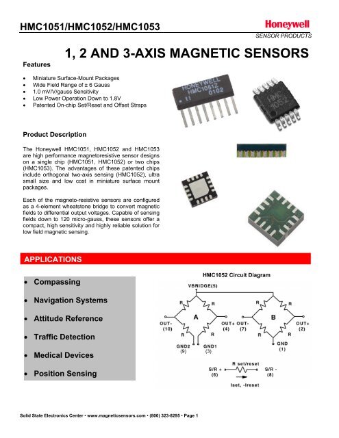
HMC1051/<strong>HMC1052</strong>/HMC1053FeaturesSENSOR PRODUCTS1, 2 AND 3-AXIS MAGNETIC SENSORS Miniature Surface-Mount Packages Wide Field Range of ± 6 Gauss 1.0 mV/V/gauss Sensitivity Low Power Operation Down to 1.8V Patented On-chip Set/Reset and Offset StrapsProduct DescriptionThe Honeywell HMC1051, <strong>HMC1052</strong> and HMC1053are high performance magnetoresistive sensor designson a single chip (HMC1051, <strong>HMC1052</strong>) or two chips(HMC1053). The advantages of these patented chipsinclude orthogonal two-axis sensing (<strong>HMC1052</strong>), ultrasmall size and low cost in miniature surface mountpackages.Each of the magneto-resistive sensors are configuredas a 4-element wheatstone bridge to convert magneticfields to differential output voltages. Capable of sensingfields down to 120 micro-gauss, these sensors offer acompact, high sensitivity and highly reliable solution forlow field magnetic sensing.APPLICATIONS Compassing<strong>HMC1052</strong> Circuit Diagram Navigation Systems Attitude Reference Traffic Detection Medical Devices(9)(3) Position SensingSolid State Electronics Center • www.magneticsensors.com • (800) 323-8295 • Page 1
HMC1051/<strong>HMC1052</strong>/HMC1053SPECIFICATIONSSENSOR PRODUCTSCharacteristics Conditions* Min Typ Max UnitsBridge ElementsSupply Vbridge referenced to GND 1.8 3.0 20 VoltsResistance Bridge current = 10mA 800 1000 1500 ohmsOperatingAmbient -40 125 °CTemperatureStorageAmbient, unbiased -55 150 °CTemperatureHumidity Tested at 85°C 85 %Field Range Full scale (FS) – total applied field -6 +6 gaussLinearity ErrorBest fit straight line± 1 gauss± 3 gauss0.10.5%FS± 6 gauss1.8Hysteresis Error 3 sweeps across ±3 gauss 0.06 %FSRepeatability Error 3 sweeps across ±3 gauss 0.1 %FSBridge OffsetOffset = (OUT+) – (OUT-)-1.25 ±0.5 +1.25 mV/VField = 0 gauss after Set pulseSensitivity Set/Reset Current = 0.5A 0.8 1.0 1.2 mV/V/gaussNoise Density @ 1kHz, Vbridge=5V 50 nV/sqrt HzResolution 50Hz Bandwidth, Vbridge=5V 120 gaussBandwidth Magnetic signal (lower limit = DC) 5 MHzDisturbing FieldSensitivity starts to degrade.20 gaussUse S/R pulse to restore sensitivity.SensitivityT A = -40 to 125°C, Vbridge=5V -3000 -2700 -2400 ppm/°CTempcoT A = -40 to 125°C, Ibridge=5mA-600Bridge OffsetT A = -40 to 125°C, No Set/Reset±500ppm/°CTempcoT A = -40 to 125°C, With Set/Reset±10Bridge OhmicVbridge=5V, T A = -40 to 125°C 2100 2500 2900 ppm/°CTempcoCross-Axis Effect Cross field = 1 gauss, Happlied = ±1 gauss ±3 %FSMax. ExposedNo perming effect on zero reading 10000 gaussFieldSensitivity Ratio ofT A = -40 to 125°C 95 100 105 %X,Y Sensors(<strong>HMC1052</strong> Only)X,Y sensorSensitive direction in X and Y sensors 0.01 degreeOrthogonality(<strong>HMC1052</strong>)* Tested at 25°C except stated otherwise.Solid State Electronics Center • www.magneticsensors.com • (800) 323-8295 • Page 2
HMC1051/<strong>HMC1052</strong>/HMC1053SENSOR PRODUCTSSPECIFICATIONSCharacteristics Conditions* Min Typ Max UnitsSet/Reset StrapResistance Measured from S/R+ to S/R- 3 4.5 6 ohmsCurrentResistanceTempcoOffset Straps0.1% duty cycle, or less,2sec current pulse0.4 0.5 4 AmpT A = -40 to 125°C 3300 3700 4100 ppm/°CResistance Measured from OFFSET+ to OFFSET- 12 15 18 ohmsOffsetConstantResistanceTempco* Tested at 25°C except stated otherwise.DC CurrentField applied in sensitive direction10 mA/gaussT A = -40 to 125°C 3500 3900 4300 ppm/°CPIN CONFIGURATIONS (Arrow indicates direction of applied field that generates a positiveoutput voltage after a SET pulse.)HMC1051Vcc(3)HMC1051Z PinoutBRIDGE AHMC1051BRIDGE BHONEYWELLHMC1051ZVo+(A)(2)GND Plane(4)Vo-(A)(8)GND1(B)(1)GND2(B)(5)1 2 3 4 5 6 7 8S/R+(6)Set/Reset StrapS/R-(7)HMC1051ZLHMC1051ZL Pinout8VB7VO+654OFF+GND VO-21S/R+OFF-3S/R-Solid State Electronics Center • www.magneticsensors.com • (800) 323-8295 • Page 3
HMC1051/<strong>HMC1052</strong>/HMC1053<strong>HMC1052</strong>Vcc(5)SENSOR PRODUCTS<strong>HMC1052</strong> Pinout10 9 8 7 6<strong>HMC1052</strong>BBRIDGE ABRIDGE B<strong>HMC1052</strong>AOUT-(10)GND2(9)GND1(3)OUT+(4)OUT-(7)GND(1)OUT+(2)1 2 3 4 5S/R+(6)Set/Reset StrapS/R-(8)<strong>HMC1052</strong>L<strong>HMC1052</strong>L PinoutHMC1053HMC1053 PinoutSolid State Electronics Center • www.magneticsensors.com • (800) 323-8295 • Page 4
HMC1051/<strong>HMC1052</strong>/HMC1053PACKAGE OUTLINESSENSOR PRODUCTSPACKAGE DRAWING HMC1051Z (8-PIN SIP)SymbolAA1BDEeHhMillimetersMin Max1.371 1.7280.101 0.2490.355 0.4839.829 11.2533.810 3.9881.270 ref6.850 7.3000.381 0.762Inches x 10E-3Min Max54 684 1014 19387 443150 15750 ref270 28715 30PACKAGE DRAWING HMC1051ZL (8-PIN IN-LINE LCC)PACKAGE DRAWING <strong>HMC1052</strong> (10-PIN MSOP)SymbolAA1BDE1eEL1MillimetersMin Max- 1.100.05 0.150.15 0.302.90 3.102.90 3.100.50 BSC4.75 5.050.95 BSCInches x 10E-3Min Max- 432.0 5.95.9 11.8114 122114 1222.0 BSC187 19937.4Solid State Electronics Center • www.magneticsensors.com • (800) 323-8295 • Page 5
HMC1051/<strong>HMC1052</strong>/HMC1053SENSOR PRODUCTSPACKAGE DRAWING <strong>HMC1052</strong>L (16-PIN LCC)SymbolMillimetersmin maxA 0.80 1.00A1 0 0.05A30.20 REFb 0.18 0.30D3.00BSCD2 1.55 1.80E3.00BSCE2 1.55 1.80e0.50BSCL 0.30 0.50N 16ND 4NE 4r B(min)/2aaa 0.15bbb 0.10ccc 0.10PACKAGE DRAWING HMC1053 (16-PIN LCC)Solid State Electronics Center • www.magneticsensors.com • (800) 323-8295 • Page 6
HMC1051/<strong>HMC1052</strong>/HMC1053SENSOR PRODUCTSBasic Device OperationThe Honeywell HMC105X family of magnetoresistivesensors are Wheatstone bridge devices to measuremagnetic fields. With power supply applied to a bridge,the sensor converts any incident magnetic field in thesensitive axis direction to a differential voltage output.In addition to the bridge circuit, the sensor has two onchipmagnetically coupled straps; the offset strap andthe set/reset strap. These straps are Honeywellpatented features for incident field adjustment andmagnetic domain alignment; and eliminate the needfor external coils positioned around the sensors.The magnetoresistive sensors are made of a nickeliron(Permalloy) thin-film deposited on a silicon waferand patterned as a resistive strip element. In thepresence of a magnetic field, a change in the bridgeresistive elements causes a corresponding change involtage across the bridge outputs.These resistive elements are aligned together to havea common sensitive axis (indicated by arrows on thepinouts) that will provide positive voltage change withmagnetic fields increasing in the sensitive direction.Because the output only is in proportion to the onedimensionalaxis (the principle of anisotropy) and itsmagnitude, additional sensor bridges placed atorthogonal directions permit accurate measurement ofarbitrary field direction. The combination of sensorbridges in two and three orthogonal axis permitapplications such as compassing and magnetometry.The offset strap allows for several modes of operationwhen a direct current is driven through it. Thesemodes are: 1) Subtraction (bucking) of an unwantedexternal magnetic field, 2) null-ing of the bridge offsetvoltage, 3) Closed loop field cancellation, and 4) Autocalibrationof bridge gain.The set/reset strap can be pulsed with high currentsfor the following benefits: 1) Enable the sensor toperform high sensitivity measurements, 2) Flip thepolarity of the bridge output voltage, and 3)Periodically used to improve linearity, lower cross-axiseffects, and temperature effects.Cross-Axis EffectCross-Axis effect for the HMR105X series is typicallyspecified at ±3% of full scale to 1 gauss. Seeapplication note AN215 regarding this effect andmethods for nulling.Offset StrapThe offset strap is a spiral of metalization that couplesin the sensor element’s sensitive axis. In two-axisdesigns, the strap is common to both bridges and mustbe multiplexed if each bridge requires a different strapcurrent. In three-axis designs, the A and B bridges aretogether with the C bridge sharing a common node forseries driving all three bridges’ offset straps. Eachoffset strap measures nominally 15 ohms, andrequires 10mA for each gauss of induced field. Thestraps will easily handle currents to buck or boostfields through the ±6 gauss linear measurement range,but designers should note the extreme thermal heatingon the die when doing so.With most applications, the offset strap is not utilizedand can be ignored. Designers can leave one or bothstrap connections (Off- and Off+) open circuited, orground one connection node. Do not tie both strapconnections together to avoid shorted turn magneticcircuits.Set/Reset StrapThe set/reset strap is another spiral of metalizationthat couples to the sensor elements easy axis(perpendicular to the sensitive axis on the sensor die).Like the offset strap, the set/reset strap runs through apair of bridge elements to keep the overall die sizecompact. Each set/reset strap has a nominalresistance of 3 to 6 ohms with a minimum requiredpeak current of 400mA for reset or set pulses. Withrare exception, the set/reset strap must be used toperiodically condition the magnetic domains of themagneto-resistive elements for best and reliableperformance.Noise CharacteristicsThe noise density for the HMR105X series is around50nV/sqrt Hz at the 1 Hz corner, and quickly dropsbelow 10nV/sqrt Hz at 5Hz and begins to fit theJohnson Noise value at just below 5nV/sqrt Hz beyond50Hz. The 10Hz noise voltage averages around 1.4micro-volts with a 0.8 micro-volts standard deviation.A set pulse is defined as a positive pulse currententering the S/R+ strap connection. The successfulresult would be the magnetic domains aligned in aforward easy-axis direction so that the sensor bridge’spolarity is a positive slope with positive fields on thesensitive axis result in positive voltages across thebridge output connections.A reset pulse is defined as a negative pulse currententering the S/R+ strap connection. The successfulSolid State Electronics Center • www.magneticsensors.com • (800) 323-8295 • Page 7
HMC1051/<strong>HMC1052</strong>/HMC1053result would be the magnetic domains aligned in areverse easy-axis direction so that sensor bridge’spolarity is a negative slope with positive fields on thesensitive axis result in negative voltages across thebridge output connections.Typically a reset pulse is sent first, followed by a setpulse a few milliseconds later. By shoving themagnetic domains in completely opposite directions,any prior magnetic disturbances are likely to becompletely erased by the duet of pulses. For simplercircuits with less critical requirements for noise andApplication NotesLow Cost 2-Axis CompassSENSOR PRODUCTSaccuracy, a single polarity pulse circuit may beemployed (all sets or all resets). With these uni-polarpulses, several pulses together become close inperformance to a set/reset pulse circuit. Figure 1shows a quick and dirty manual pulse circuit for unipolarapplication of pulses to the set/reset strap.5 voltsFigure 1Set Pulse CircuitIsetVery high precision measurements can be made using the HMC105X family of sensors when interfaced with lownoise amplifiers and 12 to 16-bit Analog-to-Digital (A/D) converters. For lower resolution (3° accuracy or more) or lowcost compass applications, 8 or 10-bit A/D converters may be used with general purpose operational amplifiers.Figure 2 shows a typical 2-axis compassing application using readily available off-the-shelf components.The basic principle of two-axis compassing is to orient the two sensor bridge elements horizontal to the ground(perpendicular to the gravitational field) and to measure the resulting X and Y analog output voltages. With theamplified sensor bridge voltages near-simultaneously converted (measured) to their digital equivalents, the arctangentY/X can be computed to derive the heading information relative to the X-axis sensitive direction. See theapplication notes on compassing at Honeywell Magnetic Sensors website (www.magneticsensors.com) for basicprinciples and detailed application information.Vcc2.5 to 3.6vU11nf500k5.00kLMV358<strong>HMC1052</strong>5.00k500kVref/21nfU2500k10U3MAX1118enabledata_outclk_in5.00kLMV358Vref5.00kset/reset.1uf500kVref/2U4set/resetFigure 2Two-Axis Compassoffset(2) IRF7509U5_set/resetSolid State Electronics Center • www.magneticsensors.com • (800) 323-8295 • Page 8
HMC1051/<strong>HMC1052</strong>/HMC1053SENSOR PRODUCTSSet/Reset Circuit NotesThe above set/reset circuit in Figure 1using theIRF7507 dual complementary MOSFETs is shown indetail by Figure 2 in its H-bridge driven configuration.This configuration is used primarily in battery operatedapplications were the 500mA nominal set/reset pulsedcurrents can be best obtained under low voltageconditions..1f1f+-DDVsrSIRF7509(P)G200Vccset/resetThe 200-ohm resistor trickle charges the 1uf supplyreservoir capacitor to the Vcc level, and isolates thebattery from the high current action of the capacitorsand MOSFET switches. Under conventional logic statesone totem pole switch holds one node of the 0.1ufcapacitor low, while the other switch charges Vcc intothe capacitors opposite node. At the first logic change,the capacitor exhibits almost a twice Vcc flip of polarity,giving the series set/reset strap load plenty of pulsecurrent. A restoring logic state flip uses the 0.1ufcapacitors stored energy to create a second nearlyequal but opposite polarity current pulse through theset/reset strap.For operation at normal 3.3 or 5-volt logic levels, asingle complementary MOSFET pair can be used in asingle ended circuit shown in Figure 4. Othercomplementary MOSFET pairs can be used with thecaution that the chosen devices should have less than0.5 ohms ON resistance and be able to handle theneeded supply voltages and set/reset currents. Notethat even a 1Hz rate of set/reset function draws anaverage current of less than 2 microamperes.Rset/resetRset/reset44DDSS.1fVsrIRF7509(P)GGIRF7509(N)1f+-DDSVsrSSGIRF7509(N)Figure 3H-Bridge DriverIRF7509(P)GG200IRF7509(N)_set/resetVccset/resetFigure 4Single-Ended DriverMagnetic Field DetectionFor simple magnetic field sensing applications such Magnetic Anomaly Detectors (MADs) and Magnetometers, asimilar circuit to the compass application can be implemented using one, two, or three magnetic sensors. In theexample circuit in Figure 5, a HMC1051Z sensor bridge is used with a low voltage capable dual op-amp to detectsufficient intensity of a magnetic field in a single direction. Uses of the circuit include ferrous object detection such asvehicle detection, a “sniffer” for currents in nearby conductors, and magnetic proximity switching. By using two orthree sensor circuits with HMC1051, <strong>HMC1052</strong>, or HMC1053 parts, a more omni-directional sensing pattern can beimplemented. There is nothing special in choosing the resistors for the differential op-amp gain stages other thanhaving like values (e.g. the two 5k and the 500k resistors) matched at 1% tolerance or better to reject commonmodeinterference signals (EMI, RFI). The ratio of the 500k/5k resistors sets the stage gain and can be optimizedfor a specific purpose. Typical gain ratios for compass and magnetometer circuits using the HMC105X family, rangefrom 50 to 500. The choice of the 5k value sets impedance loading seen by the sensor bridge network and shouldbe about 4 kilo-ohms or higher for best voltage transfer or matching. Note that Figure 5 also shows an alternativeset/reset strap driver circuit using two darlington complentary paired BJTs as electronic switches.Solid State Electronics Center • www.magneticsensors.com • (800) 323-8295 • Page 9
HMC1051/<strong>HMC1052</strong>/HMC1053U1Vcc.1f500k5.0v5.00k-TLC0725.00k+U2500kVcc/2HMC1051Vcc* Low ESR Tantalum2001f*-+10kVcc10k potThreshold Set-TLC072+10koutputLEDRLEDSENSOR PRODUCTSset/resetFMMT717.1ufFMMT617set/reset0.1foffsetFigure 510kR tempcobRstandoff distancenetworkaVcc = 9VdcU1.1f500kR th-5.00kRC4458-RC4558+output+5.00kU2500kVcc/2 ~ +4.5VdcHMC1051Vcc =9Vdc* Low ESR Tantalum2001f*I -+acAlternating or Direct Current SensingThe HMC105X family sensors can be utilized in a novel way for moderate to high current sensing applications usinga nearby external conductor providing the sensed magnetic field to the bridge. Figure 6 shows a HMC1051Z used asa current sensor with thermistor element performing a temperature compensation function for greater accuracy overa wide range of operational temperatures. Selection of the temperature compensation (tempco) resistors useddepends on the thermistor chosen and is dependant on the thermistor’s %/°C shift of resistance. For best op-ampcompatibility, the thermistor resistance should be above about 1000 ohms. The use of a 9-volt alkaline battery supplyis not critical to this application, but permits fairly common operational amplifiers such as the 4558 types to be used.Note that the circuit must be calibrated based on the final displacement of the sensed conductor to the measuringbridge. Typically, an optimally oriented measurement conductor can be placed about one centimeter away from thebridge and have reasonable capability of measuring from tens of milliamperes to beyond 20 amperes of alternating ordirect currents. See application note AN-209 for the basic principles of current sensing using AMR bridges.0.1fSRMagnetic Field DetectorFigure 6Current SensorI dcset/reset.1ufset/resetoffsetSi1553DLU3Conductor to beCurrent MeasuredSolid State Electronics Center • www.magneticsensors.com • (800) 323-8295 • Page 10
HMC1051/<strong>HMC1052</strong>/HMC1053SENSOR PRODUCTSThree Axis Compassing with Tilt CompensationFor full three-axis compassing, the circuit depicted in Figure 7 shows both a HMC1051 and a <strong>HMC1052</strong> used forsensing the magnetic field in three axes. Alternatively a single HMC1053 could be used for a single sensor packagedesign. A two-axis accelerometer with digital (PWM) outputs is also shown to provide pitch and roll (tilt) sensing, tocorrect the three-axis magnetic sensors outputs into to the tilt-compensated two-axis heading. The accelerometercan be substituted with a fluidic 2-axis tilt sensor if desired. For lower voltage operation with Lithium battery supplies(2.5 to 3.6Vdc), the Set/Reset circuit should be upgraded from a single IRF7507 to the dual IRF7507 implementation(per Figure 2) to permit a minimum 1-ampere pulse (500mA per set/reset strap resistance) to both the <strong>HMC1052</strong> andHMC1051 sensors.Vcc3.3 to 5.0vU11nf500kVcc5.00k5.00k500kLMV324U3Vcc/2Vcc/2AN0AN1AN2AN3<strong>HMC1052</strong>1nf500kset/resetDO05.00kLMV324U6set/resetoffset5.00k500kVcc/2.1ufU4IRF7509VccU5CwithMultiplexedA/D Conv.set/resetVccU2.1f500kTwo-axisaccelerometer5.00k5.00k500k-LMV324+Vcc/2xoutyoutDI0DI1HMC1051Figure 7Three Axis CompassSolid State Electronics Center • www.magneticsensors.com • (800) 323-8295 • Page 11
HMC1051/<strong>HMC1052</strong>/HMC1053SENSOR PRODUCTSDuty Cycling for Lower Energy ConsumptionFor battery powered and other applications needing limited energy consumption, the sensor bridge and supportelectronics can be switched “off” between magnetic field measurements. The HMC105X family of magnetic sensorsare very low capacitance (Bandwidth > 5MHz) sensor bridges and can stabilize quickly, typically before the supportelectronics can. Other energy saving ideas would be to minimize the quantity of set/reset pulses which saves energyover the battery life. Figure 8 shows a simple supply switching circuit that can be microprocessor controlled to dutycycle (toggle) the electronics in moderate current (